


USER MANUAL --Raiscube A8R 3D Printer
1

USER MANUAL --Raiscube A8R 3D Printer
LEGAL NOTICE
PRODUCT WARRANTY
The RAISCUBE A8R 3D Printer is covered by a limited warranty.
OVERALL PROVISIONS
All information in this user manual (“Manual”) is subject to change at any time without notice and is
provided for convenience purposes only. Shenzhen Ruisizhizao Technology CO.,LTD and our
respective affiliates and suppliers (“Raiscube”) reserves the right to modify or revise this Manual in its
sole discretion and at any time and makes no commitment to provide any such changes, updates,
enhancements, or other additions to this Manual in a timely manner or at all. You agree to be bound by
any modifications and/or revisions. Contact the Raiscube Support Team for up-to-date information. In
order to protect Raiscube proprietary and confidential information and/or trade secrets, this document
may describe some aspects of Raiscube technology in generalized terms.
DISCLAIMERS
Raiscube does not warrant the accuracy or completeness of the information, products, or services
provided by or through this Manual and assumes no responsibility for any typographical, technical, or
other inaccuracies in this Manual, which is provided “as is” and without any express or implied
warranties of any kind, including warranties of merchantability, fitness for a particular purpose, or
non-infringement of intellectual property. In connection with your use of this Manual, Raiscube shall
not be liable to you for any damages whatsoever, be they direct, economic, commercial, special,
consequential, incidental, exemplary, or indirect damages, even if Raiscube has been advised of the
possibility of such damages, including without limitation, loss of business revenue or earnings, lost
data, or lost profits. Raiscube assumes no responsibility, nor will be liable, for any damages to, or any
viruses or malware that may infect, your computer, telecommunication equipment, or other property
caused by or arising from your downloading of any information or materials related to this Manual.
The foregoing exclusions do not apply to the extent prohibited by law; please refer to your local laws
for any such prohibitions. Raiscube makes no warranties to those defined as “consumers” in the
Magnuson-Moss Warranty-Federal Trade Commission Improvement Act.
INTELLECTUAL PROPERTY
Certain trademarks, trade names, service marks, and logos (the “Marks”) used in this Manual are
registered and unregistered trademarks, trade names, and service marks of Raiscube and its affiliates.
Nothing contained in this Manual grants or should be construed as granting, by implication, estoppel,
or otherwise, any license or right to use any Marks without the written permission of Raiscube. Any
unauthorized use of any information, materials, or Marks may violate copyright laws, trademark laws,
laws of privacy and publicity, and/or other laws and regulations. Other company and/or product names
mentioned herein may be trademarks of their respective companies.
© 2009-2016 Raiscube Industries, LLC. All rights reserved.
2

USER MANUAL --Raiscube A8R 3D Printer
Reorient or relocate the machine.
Increase the separation between the equipment.
Connect the equipment to an outlet on a different circuit.
SAFETY AND COMPLIANCE
MANUFACTURER
Shenzhen Ruisizhizao Technology CO.,LTD
Floor 3, NO.18, Yaohui Industrial Park,
Dakan Industry Second Road,
Xili Street, Nanshan District,
Shenzhen, China. 518000.
RADIO AND TELEVISION INTERFERENCE
This equipment has been tested and found to comply with the limits for a Class B digital device,
pursuant to Part 15 of the Federal Communications Commission (FCC) rules. These limits are designed
to provide reasonable protection against harmful interference in a residential installation. This
equipment generates, uses and can radiate radio frequency energy and, if not installed and used in
accordance with the instructions, may cause harmful interference to radio communications. However,
there is no guarantee that interference will not occur in a particular installation. If this equipment does
cause harmful interference to radio or television reception, which can be determined by turning the
equipment off and on, the user is encouraged to try to correct the interference by one or more of the
following measures:
Any changes or modifications made to this equipment voids your authority to operate this equipment
under FCC Rules.
3

Precautions
Warning: The printer can only be used with original power supply, or the product may be damaged, with a risk of
fire.
Warning: The RAISCUBE A8R generates high temperatures. To avoid burning, or model deformation, do not
touch the model, nozzle, or the platform by hand, or any other part of the body, while the printer is working or
immediately after it has finished printing.
Warning: There is a slight smell from ABS when it is being extruded. The smell is, however, not too unpleasant.
Operate in a well ventilated room but draught free. Draught can affect warping of ABS prints. When ABS is burnt
is releases toxic fumes.
Warning: Do not use ABS plastic or its printed parts near any kind of heat source, flames, fireworks, candles,
light bulbs, etc. ABS will catch fire and burn a thick black smoke.
Warning: Always have adult supervision when children are present. Please keep all small printed parts away
from young children, choking hazards! There are several safety issues, small tools, sharp tools and HOT
objects and most parts used in connection with the 3D Printer. Tie back long hair and loose clothing. Keep
fingers away from moving parts.
Warning: Tools and parts should be stored at a suitable height away from small children.
Caution: The socket outlet must be located near the equipment and must be easily accessible.
Caution: In case of emergency disconnect the RAISCUBE A8R from the wall socket.
Caution: The RAISCUBE A8R melts plastic during printing. Plastic odors are emitted during this operation.
Make sure to set up the RAISCUBE A8R in a well-ventilated area.
Warning: Do not leave the RAISCUBE A8R unattended during operation.
USER MANUAL --Raiscube A8R 3D Printer
4

USER MANUAL --Raiscube A8R 3D Printer
Build Instruction of Raiscube A8R 3D Printer
Simply we can divide A8R into four segments – Frame, Build Platform, X&Z Motion, and circuit.
We are going to build it one by one in order. Therefore, four major steps to go completing it,
taking 1-3 hours from package to make it on in right way.
Ahead of building, get all parts including tools and screws out of box (Please refer to its
packing list for all parts), and check all if any damage exists, especially the wires and their
connectors. And Switch PSU to the correct position according to the voltage in your country.
E.g: 110V for US, 220V for UK.
STEP ONE, FRAME BUILD. Build Aluminum frame first and add remains to it in next three
steps.
First step, We need, left frame module, right frame module, Z Axis Stepper (R&L), Y Axis
Stepper, frame crossbeam, middle bottom plate, back plate, M3 Hex Key Wrench, and 18pcs
of M3*10 Socket Cap Screws. Please pick them from A8R package refer to Fig.b01.
Fig.b01
5

USER MANUAL --Raiscube A8R 3D Printer
STEP 1-1 Connect Z Axis Stepper (R&L) middle bottom plate, please differentiate Left
stepper from right stepper by the sideway hole as in Fig.b02, and we will get as in Fig.b03.
Here we we need 4 pcs of M3*10 Socket Cap Screws, 2pcs each side.
Fig.b03
Fig.b02
6

USER MANUAL --Raiscube A8R 3D Printer
STEP 1-2 Connect “Left Frame Module” & “Right Frame Module” & what done in Step 1-1
(Fig.b03) together by 4 pcs of M3*10 Socket Cap Screws, 2pcs each side.
Please check Fig.b04, and we got what as in Fig.b05.
Fig.b04 Fig.b05
STEP 1-3 Pick out “Back Plate” “Y Axis Stepper” and 2pcs of “M3*10 Socket Cap Screws”,
let “Y Axis Stepper” join “Back Plate” using the screws. Please refer to Fig.b06 and Fig.b07 for
this substep.
Fig.b06 Fig.b07
STEP 1-4: Add what done in step 1-3 to the main frame which was done in step 1-2, and
fasten them by 4pcs of M3*10 socket cap screws. From Fig.b08 to Fig.b09, it illustrates how is
this going.
Fig.b08 Fig.b09
7

USER MANUAL --Raiscube A8R 3D Printer
STEP 1-5: Add crossbeam. Find “Frame Crossbeam” in the package and also 4pcs of M3*10
Socket Cap Screws, connect it to main frame as in Fig.b10 and Fig.b11. Now we have finished
building A8R frame. Double check it again to make sure everything in the right way as in
pictures. Afterwards, time to move to next major step – Build Platform assembly.
Fig.b10 Fig.b11
STEP TWO – “Build Platform” assembly.
“Build Platform” is a function module including “hotbed” and its “ “H” support plate”, 2pcs of
420mm threaded rods, 2pcs of 390mm rods, front plate, a belt, and 12pcs M8 nuts, 12sets of
M8 Nut-Spacer-washer, to install these we need 2pcs of M8 wrench, and 2pcs of zip-tie.
Please refer to Fig.b12 and “Packing List” to pick all these elements out.
Fig.b12
8

USER MANUAL --Raiscube A8R 3D Printer
“Build Platform” includes three layers, first layer is at the bottom made by two pcs of 420mm
threaded rod along with 6 pairs of nut sets, which across back plate, middle plate, and front
plate, and each plate is locked by two pairs of M8 Nut set along the threaded rods, each pair of
nuts set on both sides of each plate. Second layer is the moving system, includes Y Axis
stepper, Belt, belt bearing behind front plate, 390mm rods, (which go through four linear
bearings beneath “H” plate, cross over middle plate and heads covered by holes of front and
back plate), “H” module. And hotbed on the top for third layer. These three layers are
combined together to form a movable “Build Platform”. In brief, what got to do is to turn Fig.b13
into Fig.b14.
Fig.b13 Fig.b14
Layer by layer, simply we divide STEP TWO into four substeps, well why not three, we need to
connect double Z threaded rods to both Z Steppers respectively. preparation for STEP
THREE.
STEP 2-1: Fasten 420 threaded rods to the frame with 4 pairs of M8 nut set. One pair of each
hole point, two pairs of each plate. Here we need two M8 wrenches, 4 pairs of M8 Nut sets,
and two pcs of 420mm threaded rods. Please refer to “video demo” in SD Card to get details of
how to stack nut set and how to place each nut set along threaded rods.
Following Fig.b15, Fig.b16 show what looks like before and after this substep.
Fig.b15 Fig.b16
9

USER MANUAL --Raiscube A8R 3D Printer
STEP 2-2: Complete installation of second layer of “build platform”. To make sure it move
smoothly, we need to insert rods through four linear bearings, and test if “H” module runs well
on 390mm rod rail. If not, adjust screws which fasten linear bearings and “H” plate until it is.
Fig.b17 and Fig.b18 are offered to help understand these actions. Let’s call this “H Train”.
Fig.b17 Fig.b18
Coming after is to integrate “H train”, front plate, and belt into printer frame. Please see Fig.b19
and get ready of these. And then place “H train” over middle plate and bury rods’ heads into
back plate, and screw 4cm distance of M8 Nut set (spacer facing front plate) along 420mm
threaded rods, add front plate to rods and lock them with threaded rods by two more nut sets.
Adjust nuts on threaded rod and front plate to cover 390mm rods. Insert belt through Y support
rack behind front plate, one head attach to “H” plate, the other mount on synchronizing pulley
and then attach to “H” plate. Please refer to Fig.b21 of how to attach belt to “H” plate.
Then Fig.b20 is what when done so far.
Fig.b19 Fig.b20
10

USER MANUAL --Raiscube A8R 3D Printer
Fig.b21
STEP 2-3: Add Hotbed. We need hotbed plate(1pc), M3*25 screw (4pcs), M3 nut (4pcs) as
in Fig.b21. M3*25 screws insert from upper side and lock it with M3 nut from the other side. We
get in Fig.b22 when done here. And then, place hotbed over “H” plate, springs along each
screw and press down through holes against “H” plate, lock each screw from downside with
Knurl Nut. Please refer to Fig.b23 and Fig.b24 when doing.
PS: Heat bed power cord shall be on right (to connect to controller) when installed.
Fig.b21 Fig.22
Fig.b23 Fig.b24
11

USER MANUAL --Raiscube A8R 3D Printer
STEP 2-4: Connect 2pcs of 350mm threaded rods to “Flexible Couple” on Z steppers and
tighten them by driving set screws. (Fig.b25 to Fig.b26) Please note that there shall be 1-3mm
free space between motor shaft and 350 threaded rods. (Fig.b27)
Fig.b25 Fig.b26 Fig.b27
12

USER MANUAL --Raiscube A8R 3D Printer
1. Extruder Module. -- 1pc
2. Left Link Block. -- 1pc
3. Right Link Block.(including M8*15 Set screw and its washer) -- 1pc
4. 350mm rod. -- 2pcs
5. Top Lock plate. -- 1 pair.
6. Filament Rack -- 1 pair.
7. M3*10 socket cap screws and hex key.
8. Belt 1pc
9. Zip-tie 2pcs
10. Control Panel Cable 2pcs
11. Hex Wrench 2pcs
12. Control Panel
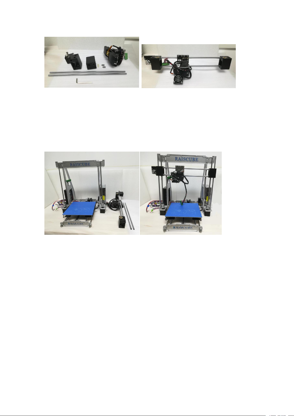
STEP THREE. X&Z motion part installation.
Now in this step, time to enable motion function of X Axis and Z Axis. Here is a part list
required to complete this step and there are as in Fig.b28, please pick out them all from
packing box. When Step 3 all done, will be as in Fig.b29.
Fig.b28 Fig.b29
STEP 3-1,
Connect Left link block, extruder module, and right link block one by one together by 350mm
rod, check if extruder module is free to run on rod rail backwards and forwards. Then, we get
“X Axis module” ready to integrating into main machine body. Fig.b30 and Fig.b31 for this
substep.
13
USER MANUAL --Raiscube A8R 3D Printer
Fig.b30 Fig.b31
STEP.3-2. Add “X Axis module” to machine body. Please note there is threaded hole in each
link block, please target this over onto threaded rods which are with Z motors. And then turn
“flexible couplings” downside by Z motor to screw down “X Axis Module” evenly. Please refer
to Fig.b32 and Fig.b33 for this.
Fig.b32 Fig.b33
STEP.3-3 Construct its roof. Please have the pair of Top Lock Plate, filament rack, and 8pcs
of M3*10 screws and one allen key too. They are as in left of Fig.b34, And Fig.35 shows what
will be like when done this substep.
14

Fig.b34 Fig.35
STEP 3-4 Add Control Panel.
USER MANUAL --Raiscube A8R 3D Printer
We need panel control, allen key, two M3*12 Screw (Fig.b36). Connect it to Crossbeam
behind (Fig.b37).
Fig.b36 Fig.b37
STEP 3-5 X Axis Belt, X end-stop, M8*15 Set screws.
A. Same as Y-belt, mount X-Belt on left&right block, and zip-tie to extruder from both
sides.(Fig.38)
B. Get X end-stop with its support from motherboard module, and place its support on upper
left rod, move to the location where stop extruder moving left when nozzle on left edge of
hotbed. (Fig.b39)
C. Together with M8*15 set screw there are two ABS spacers too. Insert into two hole on right
side of right link block, and drive M8*15 set screws to tighten rods. (Fig.b40)
15

USER MANUAL --Raiscube A8R 3D Printer
Fig.b38
Fig. b39 Fig.b40
So far, we have done the build structure of RAISCUBE A8R 3D Printer. One thing remaining
before printing -- Circuit Installation. Let’s go for step 4.
16

USER MANUAL --Raiscube A8R 3D Printer
STEP FOUR
What remaining is circuit connection, including end-stops. There are several wire terminals to
connect to its matching terminal one by one. Please refer to the marks to make it easier.
Please note that it is required to install X Axis end-stop at this step two. Please locate “X
end-stop support” on left of upper rod, where its switch get triggered when Nozzle just reaches
left margin of hotbed.
A8R wire is pre-assembled, thus to connect circuit, need to read marks on each cord, and
match one with the other of same mark. For example, “Y Axis End-stop” with “Y Axis En-stop”
as in Fig.w01. And Fig.w02 shows joints of connection between motherboard and other
function modules in circuit.
Fig.w01 Fig.w02
Please also note that when connecting motherboard to power supply, there are one red, and
one black cord piece. Red for “V+”, Black for “COM”. (Fig.w03). Please note that there is one
more Red cord connecting to the PSU “V+” from Heat bed. In fact, Heat bed Red cord (“+”) go
to PSU “V+”, while Black Cord (“-”) connect with the terminal from Main Board.(Fig.w03-h)
Fig.w03 Fig.w03-h
17

USER MANUAL --Raiscube A8R 3D Printer
Panel Cable Connection.
There are two panel cable, to connect ports of panel control with corresponding ports on
motherboard, that is, “EXP1 to EXP1”, “EXP2 to EXP2”. Please refer to Fig.w04, Fig.w05 and
Fig.w06 for this.
Fig.w04 Fig.w05
Fig.w06
For further details, please see our wire connect file in SD Card in carton, “Wire
Connection.mp4”.
Kind Reminder: To make wire path look well, and enable moving well, please pay attention to
how the wire paths as are in Fig.w07&Fig.08.
Fig.w07 Fig.w08
18

USER MANUAL --Raiscube A8R 3D Printer
Now it is end of printer build. Connect the plug to socket nearby machine, and machine shall
be on with “Ready” on screen. We go next steps for leveling and first printing.
A8R LEVELING
Bed Leveling is a basic skills required for FDM 3D printing. Because build platform leveling has
a significant impact on printing quality. Bad work of leveling may leads to warping (lift), clogged
nozzle, can not stick to bed, etc. Thus, it is worthwhile of spending time and patience on
leveling. And you will also enjoy the benefits brought by A8R printer.
Bed Leveling includes two points -- the bottom surface of link blocks shall be parallel with
hotbed surface, and the distances of nozzle summit to each point of bed shall be same under
certain tolerance. Two main steps for leveling.
STEP ONE: Get a regular rectangle object, place it on either Z stepper, turn left and right
flexible coupling to touch the object, and place same object in same position between Z
stepper and link block, turn flexible coupling to make it reach up and down face just. Please
refer to Fig.g01 and Fig.02 for this.
Fig.g01 Fig.g02
19

USER MANUAL --Raiscube A8R 3D Printer
STEP TWO: Even bed. We aim to make same distance of it between nozzle and bed in
different positions. In our case, we make point of four corners to stand for all other positions. (It
makes sense since bed is absolutely even made). Let’s make sequences as “Front Left” --
“Front Right” -- “Back Right” -- “Back Left” and “Back Right” -- “Front Right” -- “Front Left”.
There are two elements can be adjusted to even bed -- M6 screw under left link block and
Hotbed Fastener Set. (Fig.g03 Left green circle is M6 screw, right green circle is “Hotbed
Fastener Set”).
Let’s adjust first point -- Front Left. First, disable the Stepper motors in the LCD menu, so we
can move the extruder and plate by hand to “Front Left”. And use “Z home” order from LCD
Screen, the M6 screw will hit Z axis End-stop switch by then. Now we check and adjust M6
screw to make the nozzle top just touch bed, or allow dragging a piece of A4 paper through.
Move extruder to “Front Right”, and “Z Home” command from Panel control, check and
adjust the thumbscrew under hotbed to make he nozzle top just touch bed, or allow dragging a
piece of A4 paper through. Repeat this step in other point by sequence set above.
For further detailed information, please find on http://reprap.org/wiki/Leveling_the_Print_Bed .
Fig.g03 Fig.g04
PRINT TEST.
Whether it is well leveled or not, we need to test. To print a model and particular observe how
the first few layers are stick to bed. If not good enough, we need to stop printing and check and
adjust leveling again, or review and check other steps during full installation.
Further details of printing, let’s go next to “sample print show”.
20

USER MANUAL --Raiscube A8R 3D Printer
Sample Print Show.
Since we have get A8R ready for printing after leveling, now go further steps to our first print.
Let’s say steps are
1. Source file Acquirement
2. Slicing origin file with Cura, Simplied 3D or other slicing software.
3. Transfer sliced file to 3D Printer.
4. Print.
5. Remove prints.
6. Evaluate print quality.
Let’s take an example to go through these steps.
Source file acquirement. Get “.stl” or “.object” design files from any design software (e.g
freecad, pro-E, etc), or we can download online. In our case, we download one from
https://www.thingiverse.com/thing:1278865. Extract “xyzCalibration_cube.stl” from download
zip file. Now we have the “.stl” file. (Fig.s01)
Fig.s01
Slicing: Load it to Cura software. Configure slicing parameters in Cura. (Fig.s02) If you have
no Cura installed in your PC, please find it in the SD Card which in printer package, and install
it step by step. You also refer to “Cura 15.04 installation guide.pdf” in SD Card file.
Fig.s02
21

USER MANUAL --Raiscube A8R 3D Printer
Transfer file to Print: “save GCode..” to SD Card. (Fig.s03)
Fig.s03
Print: In 3D control panel, press and turn the control button to print from SD Card. “Main Menu”
--- Print From SD Card --- xyzCalibration_cube.stl, choose this and printing screen on with
info of current print. (Fig.s04)
Fig.s04
22

USER MANUAL --Raiscube A8R 3D Printer
Remove print: When print done, Extruder will lift and go back to its origin (front left most
point of hotbed). Use a spatula (enclosed in package) to move the cube. (Fig.s05)
Fig.s05
Evaluate print quality: In our cases, warping happens due to leveling issue, adjust hotbed and
solved. A regular cube model is printed. When measure its dimension, it should be
20*20*20mm, our print is 20.08*20.02*20.04mm. (Fig.s06, Fig.s07)
Fig.s07
Fig.s06
23

USER MANUAL --Raiscube A8R 3D Printer
Resource List for you may help
Reprap Facebook Group: https://www.facebook.com/groups/1068531466501015
Youtube Installation Demo: https://youtu.be/oJS6ODX52ng
Youtube Build Video: https://youtu.be/OweEknLShZ0
Raiscube A8R Live Build: https://youtu.be/C2OinymgcIg
Designed in UK&US, Manufactured By Shenzhen Rise Technology CO.,LTD
24
 Loading...