


®
MHP75A / MHP150A
User Manual
It is the installer’s responsibility to read, understand, and comply with these instructions.

Your commitment to saving water through the use of harvested rainwater is commendable, and is a very
important step towards increasing your personal water sustainability.
To match your commitment to saving water we have committed to ensuring that the pumps and pump
controllers we offer are of the highest quality available.
Please Note:
This appliance is not intended for use by persons (including children) with reduced physical, sensory or
mental capabilities, or lack of experience and knowledge, unless they have been given supervision or
instruction concerning use of the appliance by a person responsible for their safety. Children should be
supervised to ensure that they do not play with the appliance.
Mainly applicable for pumping industrial fluids, such as mineral water, soft
water, pure water, clean oil and circulation and boosting of other weak
chemical-industrial mediums.
• Rainwater harvesting systems
• Greywater systems
• Water treatment processes
• Industrial cleaners and dishwashers
• Water boosting applications
• Heating and cooling for industrial processes
• Air-conditioning systems
• Air freshening, heater device (soft water)
• Water supply and boosting (drinking water, light chlorine water)
• Fertilization/metering system
• Liquid temperature: 0℃ ~ 70℃; 32℉ ~ 158℉
• Maximum environmental temperature: 50℃ (122℉)
• Maximum operating pressure: 10 bar (145 PSI)
• Maximum suction pressure is limited by maximum operating pressure
• 2-pole induction motor
• Single-phase: 110-120/60Hz
• Input thermal protector
• Insulation class: F
• Protection: IP55
Thank you for your purchase of a RainFlo Pump!
1) Applications:
2) Operation Conditions:
3) Motor:

• This pump is made for indoor use only.
• To prevent suction loss, install the pump as close to the water
source as possible.
• Mount the pump securely using the base plate bolt holes.
• Minimize bending any attached pipes.
• Make sure the connections are water tight and ensure the pipes
are supported independently.
• Install a pressure gauge in the discharge pipes to allow proper
monitoring and diagnostics.
• Ensure the input voltage (V), frequency (Hz), and phase (PH)
matches the specifications marked on the label. When the
voltage is greater than ± 10V, the thermal protector will shut off
the pump.
• Ensure the pump is reliably grounded with a circuit breaker.
• The power cord should be less than 15 feet and approved for the
current delivered to this pump.
• Ensure that you have made the correct electrical connections for
the pump.
• To avoid burning the seal and damaging the pump, never let the
pump run without water.
• The fan should turn freely by hand when disconnected from
power and water.
• The fan should rotate clockwise when viewed from the back of
the pump
• For proper startup, fill at the discharge drain plug to prime it.
• To begin the flow, turn on the pump and open the discharge
valve.
• Before stopping the pump and disconnecting the power, close
the upstream discharge valve to avoid siphoning.
• Avoid excessive start and stop operations.
5) Electrical Connection:
6) Starting, Operation, and Stopping the Pump:
4) Installation:

• Disconnect pump when power is interrupted or unstable.
• To avoid overheating, don’t restrict the suction end to adjust flow.
• Install a dry-run shut off switch to prevent damage.
• If there are any abnormal noises, stop the pump immediately and
check the connections, hose clamps, etc.
• If the pump will remain unused for an extended time, be sure to
drain the water to prevent damage from freezing water.
Problems Possible Causes Solutions
e pump does not run • Incorrect voltage.
Voltage must be
within ten volts of
the value specied
on the label)
• Fuse or thermal
protector makes the
pump stop running
• Check the voltage
on the label and
make sure the input
voltage is within 10
volts of that value
• Check the fuse or
thermal protector
for damage
e pump does not
pump properly
• e head is too high
• e water level is
too low
• Intake isn’t in water
• No water
• Leak in inlet or
outlet hoses
• Make sure the head
isn’t too high
• Verify the suction
head is in water
• Prime the pump
e pump runs but no
water
• Intake is blocked
• Impeller is corroded
• Intake isn’t in water
• Pump isn’t primed
• Leak in suction pipe
• Check suction
height
• Replace impeller
• Prime the pump
• Check for leaks
e ow reduces drastically
• Output/input pipes,
or intake could be
blocked
• Water level is too
low
• Impeller is damaged
or clogged
• Clean or replace
intake screen, if
present
• Check installation
height
• Replace impeller
e motor is overheating, or, stops soon aer
starting
• Low voltage
• Insucient ventilation in pump room
• Verify supply
voltage under load
is within 10 volts of
the required voltage
(110 volts)
• Improve ventilation
7) Maintenance:
8) Troubleshooting:
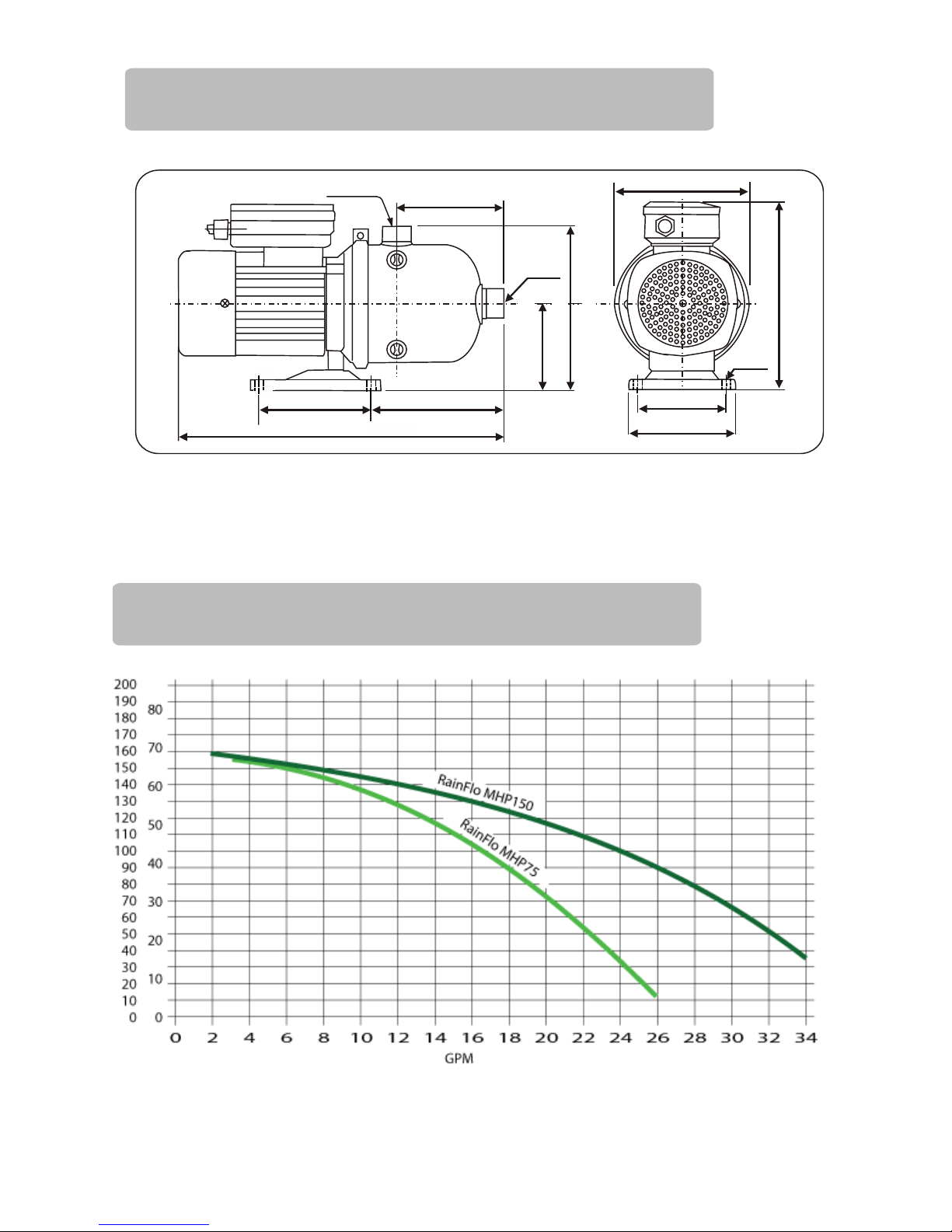
15.95
5.43
6.30
1” NPT
4.33
4.25
Ø.33
Ø13.75
5.11
9.29
8.19
Inlet*
5.11
*MHP75A Inlet is 1” NFPT / MHP150A Inlet is 1.5” NFPT
9) Dimensions:
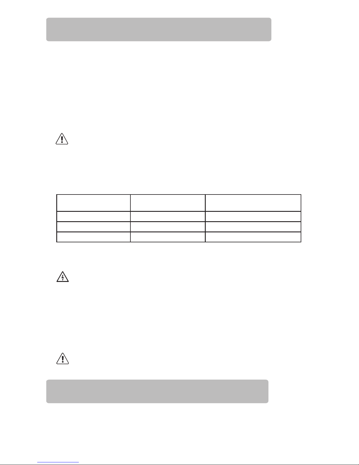
10) MHP Pump Curve:

Thank you for your purchase of a RainFlo Pump Control.
Your commitment to saving water through the use of harvested rainwater is
commendable, and is a very important step towards increasing your personal water
sustainability.
To match your commitment to saving water we have committed to ensuring that
the pump controllers we offer are of the highest quality available. This pump
controller has been tested and certified ROHS compliant for your safety.
The RainFlo PC115A provides automatic multifunction control for your water
pump including start and stop control based on user demand (flow), demand-side
pressure display via built-in pressure gauge, run-dry protection and a check valve
(non-return valve) function. It provides direct control of water pumps up to 1.25
horsepower at 115V. As with most pump controllers, the system high pressure is
based on the pump output. The pump start pressure (low pressure threshold and
start trigger), is adjustable through a screw on the back side of the unit.
Your PC115A pump controller features a built-in pressure gauge located on the
right side of the unit. As with many hydraulic devices, this gauge displays
pressure in units called “bar”. One bar is approximately equal to atmospheric
pressure at sea level. In terms of water pressure,
1 bar = 14.5037 PSI.
Pressure Gauge (bar) Pressure (PSIG)
2.0 29.0 PSI
3.0 43.5 PSI
4.0 58.0 PSI
5.0 72.5 PSI
6.0 87.0 PSI
7.0 101.5 PSI
11) Overview of Pump Controller:
13) Pressure Gauge:
12) Important Notice:
Read carefully before proceeding with product assembly and commissioning
operations. For the pump, refer to its manual.
The PC115A features an internal check valve which requires the unit to be installed
with the water inlet facing downward and the output above (arrows near the pressure
gauge facing up).

14) Applications and Operation:
The PC115A electronic controller commands the starting and stopping of singlephase electric water pumps whenever a tap or valve connected to the installation is
opened or closed, respectively. When the pump is started, it keeps running as long
as any connected tap remains open, supplying the network with the required flow
at the related pressure.
• Inlet connection : 1”
• Outlet connection : 1”
• Non-water hammer check valve.
• Dry-running protection system.
• Pressure gauge.
• Manual start button (RESET).
• AUTORESET function for automatic start after a failure.
• Power supply LED (POWER).
• Pump switch-on LED (ON).
• Safety system activation LED (FAILURE).
• Power supply voltage: 1~115-125V
• Maximum current : 16 A
• Max pump power : 1100W(1.25 HP) at 1-115-125V
• Frequency : 50/60 Hz
• Protection class : IP 65 (*)
• Ambient temperature : 0 /+140° F
• Liquid temperature : 0 /+140° F
• Max flow rate : 44 GPM
• Adjustable starting pressure : 20 - 35 PSI
• Max operating pressure : 145 PSI
(*)Provided the cable glands and screws in cover have been suitably tightened
17) Handling and Inspection:
Handle with care. Dropping and impact can damage the product.
Before proceeding with installation, make sure the unit shows no visible signs of
damage, otherwise contact your dealer.
15) Construction Characteristics:
16) Specifications:
18) Installation:
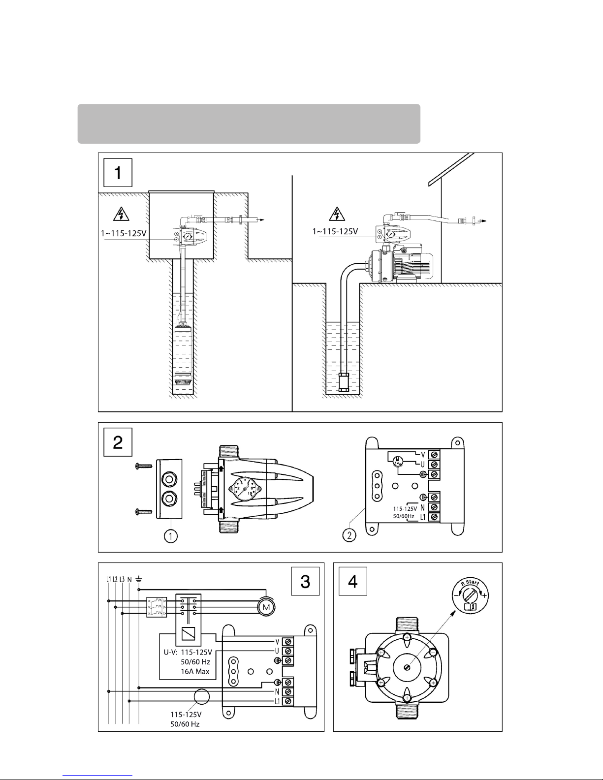
Make sure that the voltage supply corresponds to the rated voltage. Remove the cover (faceplate)
from the electronic board and make the electrical connection according to the instructions shown
inside. This controller can also be used with a single-phase pump with electrical demand greater than
16A, or a three-phase pump, using an auxiliary remote control switch (115V coil). In this case the
electrical connections must be made as shown in the diagram, Fig. 3.
18.2 Electrical Connection (Fig. 2)
START PRESSURE MAX. OPERATING
HEIGHT
MAX. PUMP PRESSURE
GREATER THAN
22 PSI 33 ft 44 PSI
29 PSI 49 ft 51 PSI
36 PSI 66 ft 58 PSI
WARNING: The maximum operating height between the pump and the highest point in the
system will depend on the pump start pressure setting. The maximum pressure of your pump
must exceed the value of the start pressure setting. Both these limits are specied in the table
below.
WARNING: Power supply voltages other than those specied or improper connections can
permanently damage the electronic components and will void the warranty.
This device must be assembled and installed by personnel qualified in accordance with local
laws, regulations and codes.
18.1 Water Connection (Fig.1)
The PC115A must always be installed with the arrows pointing upward, connecting the
1” threaded inlet to the pump’s outlet and the 1” threaded outlet to the point of use.
Use flexible pipes for connection to the water network, protecting the appliance form any
bending loads and vibrations, a ball valve to isolate the pump system from the network, and a
foot valve to maintain prime for suction inlets (Fig.1).
Before starting up the unit, ll the suction inlet with water as specied in the pump’s
manual.
H07RN-F3G1.5 type cables (9 - 12 mm) or equivalent must be used in order to
ensure IP 65 protection.
The connections must be made by a qualied electrician. Install a GFCI for protection
against lethal electric shock. Be sure the circuit and device are properly grounded.
1. Check that the pump is primed properly, then partially open a tap in the user circuit.
2. Turn on power to the controller; the power LED will light up (POWER).
3. The pump will start up automatically and within 20 to 25 seconds the system should
reach approximately the maximum pressure delivered by the pump. While the
pump is running, the corresponding LED (ON) willremain illuminated.
19)
Start Up:

4. Close the tap mentioned under step (1). After 10-12 seconds the pump will stop running, but
the power supply LED (POWER) will remain lit. Any malfunctions occurring after
these operations will be caused by improper priming or failure to prime.
21) Automatic Reset Function:
22) Troubleshooting:
1. Read the pressure indicated by the gauge when the pump is started.
2. Disconnect the power supply.
3. Open a tap to discharge the pressure.
4. Adjust the screw clockwise to increase (or counter-clockwise to decrease) the start pressure.
5. Supply power to the the controller; if you are not satisfied with the adjustment, repeat th
operations described above until you obtain the desired pressure value.
NOTE: The maximum pressure of the pump (closing contact pressure) and the minimum
start pressure must comply with the values shown in the table under paragraph 5.1 otherwise
the controller will go into FAILURE mode.
If the device goes into failure mode, the automatic reset function will execute a series of automatic
starts to attempt to restore operation without any manual intervention via the RESET button.
The system operates as follows: The appliance is in failure mode due to water failure, for example;
after five minutes in this condition the system will do a 25-second RESET, attempting to prime the
pump. If the system is able to prime the pump, the failure will disappear and the pump will be ready
to operate. However, if the failure persists, the system will do another RESET after thirty minutes,
and will continue in this manner systematically every thirty minutes for 24 hours. If the failure still
persists after all these attempts, the system will remain in this condition until the problem has been
resolved by manual intervention or when power is recycled.
closed and that there are no leaks.
B) The electrical connection is incorrect: refer to the instructions in Fig. 2.
C) Electronic board malfunction: replace the electronic board.
A) The pump is not primed; dry-run protection is active and the FAILURE LED is on: prime
the water pipe and check by pressing the manual start button (RESET).
B) The pump has shut down: the safety system has stepped in and the FAILURE LED is on.
If you press the manual start button (RESET) and the LED (ON) lights up; if the
pump does not start test the output with another device such as a lamp.
C) Electronic board malfunction: disconnect the pump from the electrical mains and
reconnect it; the pump should start, if it does not replace the controller.
D) No power supply: check the electrical connections, the POWER LED must be
illuminated.
E) The pump delivers insufficient pressure, the safety system has stepped in and the
corresponding LED (FAILURE) is illuminated: make sure that the pump
pressure corresponds to the pressure value specified in the relevant table in
section 18.1.
20) Starting Pressure Adjustment: (P. Start):
The pump controller is factory set to start with a minimum pressure of 21.75 PSI (1.5 bar). This
pressure can be increased up to 36.25 PSI (2.5 bar) by rotating the screw found at the back of the
cone-shaped end of the device, (see Fig. 4).
To set the pump start pressure:
2) THE PUMP DOES NOT START:
A) Water loss exceeding 0.8 gpm. Make sure that all the taps along the pipeline are
1) THE PUMP DOES NOT STOP:
115-125V
50/60 Hz
115-125V
50/60 Hz
16A Max
U-V:
115-125V
50/60Hz
1~115-125V
1~115-125V
N
N
23) Installation Illustrations:
F) Air is entering the pump through the suction side: the pressure is well below normal, with
constant fluctuations.
The safety system will engage and stop the pump, the
FAILURE LED will
light up. Check the seal and connections in the suction pipe.
3
THE PUMP
KEEPS STARTING AND STOPPING:
There is a small leak in the delivery pipeline: check for any leaking taps or running toilets.

3432302826 4442403836242220181614121086420
GPM
30
50
40
20
10
0
H
ft
PC115A Friction Loss

®
MHP75A / MHP150A Pump
 Loading...