

Page 1
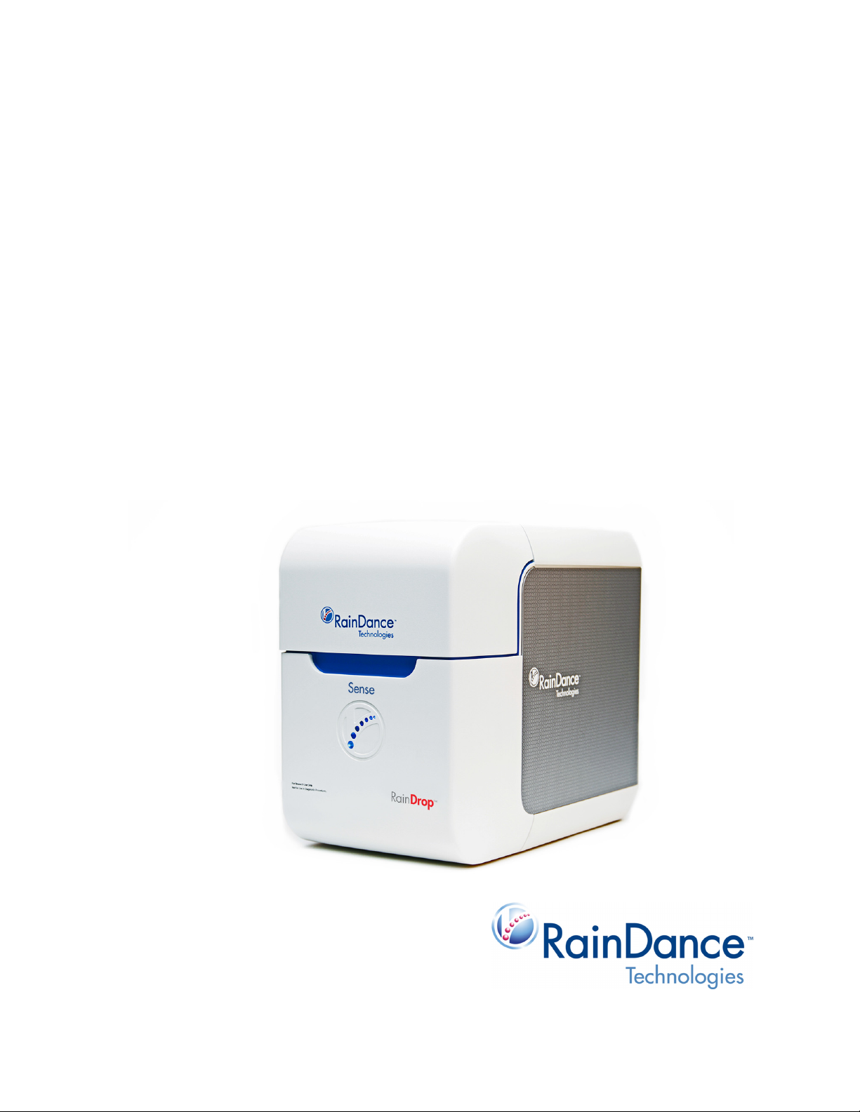
RainDrop® Sense
Operator’s Manual
Page 2

Patent, Trademarks, & Copyrights
Patent
www.raindancetechnologies.com/patents
Trademarks
RainDance Technologies, ThunderStorm, RainDrop, ThunderBolts, RainDrop Analyst II, and
RainDrop Plus and logos thereof are trademarks of RainDance Technologies, Inc. All other
brands may be trademarks of their respective holders.
Copyrights
© 2018 RainDance Technologies, Inc. All rights reserved. RainDance Technologies, Inc. owns
the copyright to the RainDance software.
Reproduction Disclaimer
You may make a reasonable number of copies of this manual for internal use only and only for
use in connection with the RainDrop Sense Instrument. All such copies shall contain the copy
right info set forth on Page ii of this manual and this reproduction disclaimer. Except as explicitly
provided by this section, neither this manual nor any part of it may be reproduced, photocopied,
or electronically transmitted in any way without the advanced written permission of RainDance.
-
Contact
RainDance Technologies, Inc.
749 Middlesex Turnpike
Billerica, MA 01821
Fax: (978) 528-6090 (support)
Web: www.raindancetech.com/support
Email: customercare@raindancetech.com
For Research Use Only. Not for use in diagnostic procedures.
Page 3

RainDrop Sense Operator’s Manual
Table of Contents
Chapter 1: Foreword 1-1
About this Manual ............................................................................................. 1-2
Intended Use..................................................................................................... 1-2
Data Entry and Collection ................................................................................. 1-2
Design Change Disclaimer................................................................................ 1-3
Reproduction Disclaimer ................................................................................... 1-3
RainDance Support........................................................................................... 1-3
Microsoft Windows Familiarity........................................................................... 1-4
Notes, Warnings, and Cautions ........................................................................ 1-4
Notes ........................................................................................................... 1-4
Warnings...................................................................................................... 1-4
Cautions....................................................................................................... 1-5
Biohazard Safety Warnings ......................................................................... 1-5
Laser Safety Warnings ................................................................................ 1-6
Safety Information............................................................................................. 1-7
Electrical Safety Warnings........................................................................... 1-7
Mechanical Safety ....................................................................................... 1-8
Gas Pressure Safety.................................................................................... 1-8
Product Labels .................................................................................................. 1-8
Safety Interlock ................................................................................................. 1-8
Packing and Transport ...................................................................................... 1-8
Chapter 2: Introduction 2-1
System Overview .............................................................................................. 2-2
RainDrop System Major Components............................................................... 2-2
RainDrop Sense Major Components ................................................................ 2-3
RainDrop Sense Layout.................................................................................... 2-4
RainDrop Sense Barcode Reader ............................................................... 2-5
RainDrop Sense Chip .................................................................................. 2-6
Handling the Sense Chip............................................................................. 2-6
RainDrop Sense Chip Compression Plate................................................... 2-7
Specifications.................................................................................................... 2-8
Chapter 3: Installation and Setup 3-1
Space Requirements......................................................................................... 3-2
Gas Connectivity.......................................................................................... 3-2
Connecting RainDrop Sense and Instrument Controller ................................... 3-3
Connecting Cables to the RainDrop Sense Instrument ............................... 3-3
Connecting Cables to the Instrument Controller.......................................... 3-4
Gas Pressure Quality ........................................................................................ 3-6
Starting Up the RainDrop Sense Instrument..................................................... 3-6
Relocating RainDrop ......................................................................................... 3-7
LCN 50-04344 Rev. D iii
Page 4

RainDrop Sense Operator’s Manual
Chapter 4: Launching the Instrument Control Software (ICS) 4-1
Introduction ....................................................................................................... 4-2
The Microsoft Windows 7 Login ........................................................................ 4-2
Starting the ICS Application .............................................................................. 4-2
ICS Login Levels.......................................................................................... 4-3
Changing the ICS Password........................................................................ 4-5
The ICS Account Types............................................................................... 4-6
ICS Initialization ........................................................................................... 4-7
Status Indicators ............................................................................................. 4-10
Using Tabs in the ICS ..................................................................................... 4-10
Navigating Through the Tabs .................................................................... 4-12
Canceling a Process.................................................................................. 4-12
Completing a Process................................................................................ 4-13
Using Scan Buttons ................................................................................... 4-13
Alarms, Log, and Status Tabs......................................................................... 4-14
Chapter 5: Performing a Sense Run 5-1
Introduction ....................................................................................................... 5-2
Gathering Supplies............................................................................................ 5-2
Starting a Sense Run........................................................................................ 5-3
Completing the ICS Setup................................................................................. 5-9
Checking the Status Indicators .................................................................... 5-9
Completing the Run Data Tab......................................................................... 5-11
Completing the Run Info Tab..................................................................... 5-14
Completing the Run Tabs Using the Import Function................................ 5-15
Using Email Notification............................................................................. 5-15
Performing the Run......................................................................................... 5-17
Canceling a Run.............................................................................................. 5-18
Handling Data ................................................................................................. 5-19
Exporting Data........................................................................................... 5-20
Moving Data Files...................................................................................... 5-21
Chapter 6: Managing the System 6-1
Introduction ....................................................................................................... 6-2
Managing Users................................................................................................ 6-2
Adding a New User...................................................................................... 6-3
Editing a User .............................................................................................. 6-5
Deleting a User............................................................................................ 6-7
Resetting Password or Unlocking an Account............................................. 6-7
Viewing Past Runs ............................................................................................ 6-8
Viewing Runs............................................................................................... 6-8
LCN 50-04344 Rev. D iv
Page 5

RainDrop Sense Operator’s Manual
Chapter 7: Support, Customer Maintenance, and Troubleshooting 7-1
RainDance Support........................................................................................... 7-2
RainDance Planned Maintenance..................................................................... 7-2
Customer Maintenance ..................................................................................... 7-2
Restarting the IC Workstation...................................................................... 7-2
Cleaning the RainDrop Sense ..................................................................... 7-2
Refilling the Oil Reservoir.................................................................................. 7-3
Service and Diagnostic Requirements .............................................................. 7-6
Powering Off the System .................................................................................. 7-6
Powering On or Restarting the System............................................................. 7-6
Restoring the System After a Failure ................................................................ 7-6
Support Agreement Information ........................................................................ 7-6
Moving the System............................................................................................ 7-7
Storing the System............................................................................................ 7-7
Reinstalling/Updating ICS Application............................................................... 7-7
Error Messages................................................................................................. 7-7
Troubleshooting ................................................................................................ 7-8
Chapter 8: Waste Management 8-1
Introduction and Disclaimer............................................................................... 8-2
Classification of Waste...................................................................................... 8-2
Anticipated Typical Waste Stream Composition ............................................... 8-3
Recommended Waste Stream Disposal ........................................................... 8-4
Chapter 9: Customer Care Information 9-1
General Care Information.................................................................................. 9-2
Consumables .................................................................................................... 9-2
Chapter 10: Regulatory Information 10-1
Sense Instrument Declaration of Conformity .................................................. 10-2
Chapter 11: Symbol Glossary 11-1
Appendix A: RainDrop
®
Consumables and Equipment A-1
LCN 50-04344 Rev. D v
Page 6

Chapter 1:
CHAPTER 1
Chapter 1:
Foreword
This chapter covers the following topics:
About this Manual page 1-1
Intended Use page 1-2
Data Entry and Collection page 1-2
Design Change Disclaimer page 1-2
Reproduction Disclaimer page 1-3
RainDance Support page 1-3
Microsoft Windows Familiarity page 1-3
Notes, Warnings, and Cautions page 1-3
Notes page 1-4
1
Warnings page 1-4
Cautions page 1-5
Biohazard Safety Warnings page 1-5
Laser Safety Warnings page 1-6
Safety Information page 1-7
Electrical Safety Warnings page 1-7
Mechanical Safety page 1-8
Gas Pressure Safety page 1-8
Product Labels page 1-8
Safety Interlock page 1-8
Packing and Transport page 1-8
About this Manual
This manual is designed to serve the operators of the RainDance Technologies®, Inc.
(hereafter called “RainDance”) RainDrop
instructions, product illustrations, screen graphics, troubleshooting, error messages, and
other relevant information are contained in this manual. It is the operator's responsibility to
ensure that all safety instructions in this manual are strictly applied.
®
Sense instrument. All material operating
Where there is any conflict between the RainDance Software End User L
included in the software, and the terms and conditions of sale, the order of precedence shall
LCN 50-04344 Rev. D 1-1
icense Agreement
Page 7

be as follows: (1) the RainDance Software End User License Agreement and (2) the terms
and conditions.
Intended Use
For Research Use Only. Not for use in Diagnostic Procedures.
RainDance Technologies RainDrop Sense is the detection instrument that enables
identification and counting of target molecules in each picoliter droplet following PCR
amplification. Together the RainDance Source and RainDrop Sense instruments make up the
RainDrop Digital PCR System delivering quantitative results.
Data Entry and Collection
RainDance requires that you do not enter health information identifiable to a particular
person, or other information that is subject to regulatory or contractual protection, into any
RainDance instrument. Such information is not protected from disclosure to service or other
personnel and, as noted below, may be included in information provided to RainDance for
purposes of servicing or evaluating the performance of your instrument.
RainDrop Sense Operator’s Manual
Further, by requesting service of your RainDance instrument, you give RainDance consent to
access and use data stored in your RainDance instrument. RainDance uses the data to
troubleshoot and service the instrument in response to your service requests. RainDance
also may aggregate data collected from your instrument in response to service requests with
similar data from other customers and may use the aggregated data to improve instrument
performance.
Your instrument from RainDance is enabled with an automatic email functionality that allows
RainDance to receive performance data from the instrument from time to time without your
knowledge. You may choose to disable that functionality. Disabling that functionality prevents
the instrument from sending such data to RainDance. The data collected with this automatic
email functionality consists of the number of samples processed, the success rate of the
samples processed, data specific to the performance of your instrument, and data that is
entered by your operators. RainDance collects this data solely so that it may better
understand and improve instrument performance. By allowing the functionality to remain
enabled, you give RainDance permission to use the automatic email functionality.
Design Change Disclaimer
Due to design changes and product improvements, information in this manual is
subject to change without notice. RainDance reserves the right to change the product
design, including illustrations, screen shots, and diagrams, at any time without notice to
anyone, which may subsequently affect the contents of this manual.
LCN 50-04344 Rev. D 1-2
Page 8

RainDance assumes no responsibility for any errors that may appear in this manual.
RainDance will make every commercially reasonable effort to ensure that this manual
is up-to-date and corresponds with the shipped RainDrop Sense Instrument.
The depictions of the workstation screens in this manual are representative only.
Depending on the hardware and software versions of the system, minor differences
may appear between the actual displays and those shown in this manual.
Reproduction Disclaimer
You may make a reasonable number of copies of this manual for internal use only and only
for use in connection with the RainDrop Sense Instrument. Except as provided by the
previous sentence, neither this manual nor any part of it may be reproduced, photocopied, or
electronically transmitted in any way without the advanced written permission of RainDance.
RainDance Support
If you have any difficulty running the RainDance Source instrument, contact your RainDance
Support representative.
solutions. The information given is general. Some applications may require additional
procedures or equipment modification. Contact RainDance Support via email:
support@raindancetech.com, Monday through Friday, excluding holidays.
Chapter 7 of this manual includes a list of problems and possible
RainDrop Sense Operator’s Manual
Microsoft Windows Familiarity
The supplied Instrument Control Software (ICS) is designed for the Microsoft®
Windows® Embedded 7 operating system and uses the standard Windows interface.
This manual assumes that you are familiar with these standard techniques: clicking the
mouse, highlighting an item, right-clicking, dragging, using the keyboard, interacting
with dialog boxes, keyboard commands, selection techniques, and other Windows
basics.
If you require assistance with these aspects of the software user interface, refer to the
Microsoft Windows documentation.
Notes, Warnings, and Cautions
The symbols described in this section are used throughout this document to draw your
attention to specific situations involving safety and proper use of the equipment. Symbols
found on the instruments are listed in
Chapter 11: “Symbol Glossary.”
LCN 50-04344 Rev. D 1-3
Page 9
Notes
Warning: A Warning indicates a potentially hazardous situation that, if not avoided,
could result in serious personal injury or death to you or others. Warnings are set
within boxed rules and indented.
RainDrop Sense Operator’s Manual
Notes are set apart from the body of the document with either the word Note or Important.
They are meant to draw your attention to reminders and information that is important to
successful operation of the RainDrop Sense Instrument.
Warnings
Note: A
Important: An
communicate greater weight to the issue at hand.
Warnings are represented by a red triangle with an exclamation point inside of it. Warnings
are reserved for situations that indicate the possibility of personal injury if the instructions are
not followed.
Note indicates a useful piece of information.
Important note is similar to a regular Note, except that it is meant to
LCN 50-04344 Rev. D 1-4
Page 10
Cautions
Caution: Do not operate the System in a manner other than specified in this
manual. Doing so could damage the instrument or produce erroneous results.
Caution: RainDance service representatives are trained in the safe operation of the
RainDrop Sense Instrument, including accessing those areas reserved for trained
service representatives.
Warning: Follow your laboratory's procedures and regulations when handling
biohazardous materials.
Warning: RainDance suggests that users be professional and conscientious and
take the appropriate safety measures when preparing, handling, and disposing of
any biohazardous samples or waste.
Warning: When working with biohazardous samples, or waste, always follow
standard universal safety procedures (lab coats, safety glasses, gloves, mask,
etc.).
Cautions are represented by a blue triangle with an exclamation point inside of it. They
indicate that you must follow a particular procedure in order to correctly operate the RainDrop
Sense Instrument and to avoid any possible damage to the equipment or loss of
consumables.
Biohazard Safety Warnings
A biohazard warning indicates that the user must use precautions, for example, gloves, when
handling biological samples, to prevent any infections or hazards that can be caused by
them.
RainDrop Sense Operator’s Manual
In addition, users should take precautions in accordance with local, state, and national
requirements.
LCN 50-04344 Rev. D 1-5
Page 11
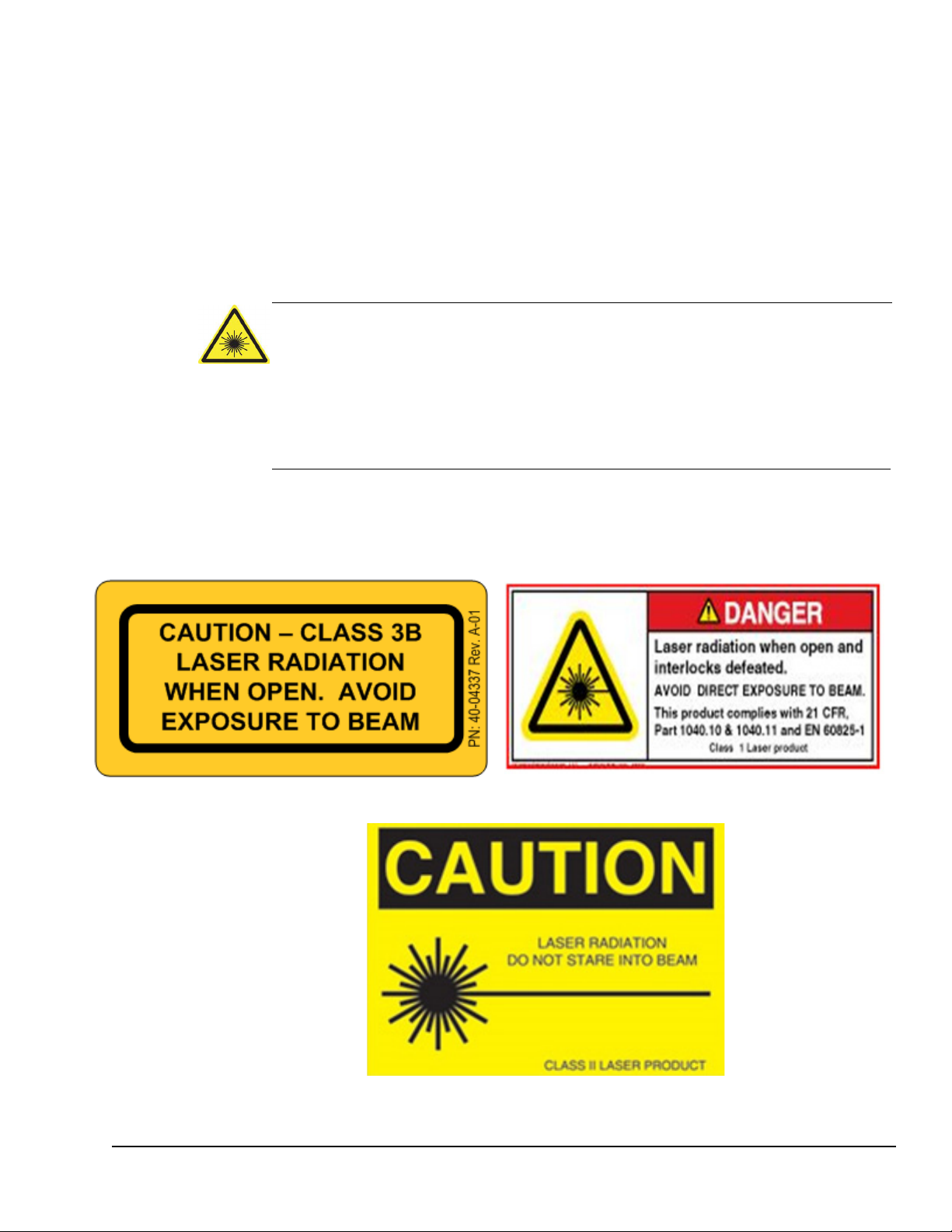
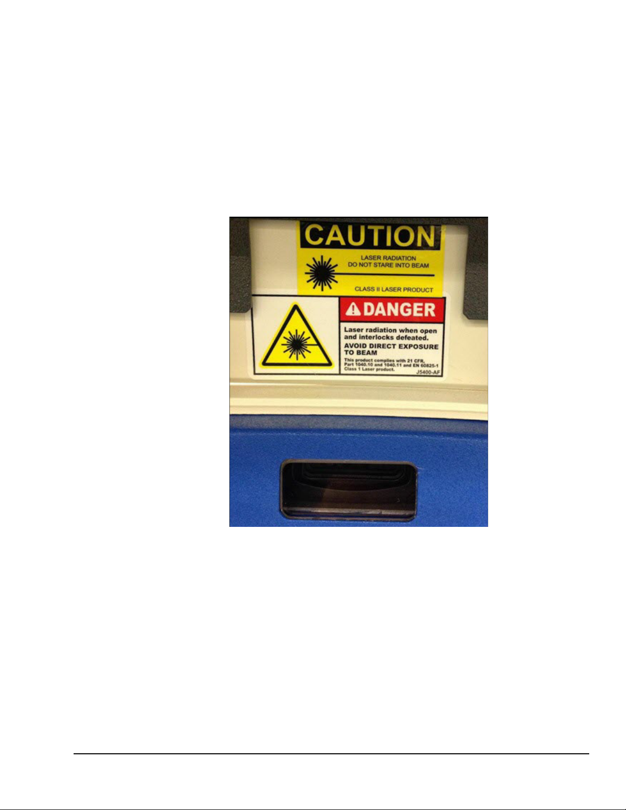
Laser Safety Warnings
Warning: A Class 3B laser is hazardous if the eye is exposed directly, but diffuse
reflections such as those from paper or other matte surfaces are not harmful. The
AEL for continuous lasers in the wavelength range from 315 nm to far infrared is
0.5 W. For pulsed lasers between 400 and 700 nm, the AEL is 30 mW. Other
limits apply to other wavelengths and to ultrashort lasers. Protective eye wear is
typically required where direct viewing of a class 3B laser beam may occur. Class3B lasers must be equipped with a key switch and a safety interlock.
The RainDrop Sense, classified as a Class 2 System, contains a Class 3B laser and Class 2
barcode laser. Avoid direct exposure to the Class 3B laser radiation when the unit is open
and interlocks are defeated. Only a qualified service person should remove the cover or
attempt to service this device, due to possible eye injury.
RainDrop Sense Operator’s Manual
A laser warning indicates that the user must use precautions whe
to avoid injury from the lasers.
In addition, users should take precautions in accordance with local, state, and national
requirements.
n operating the instrument
LCN 50-04344 Rev. D 1-6
Figure 1-1: Laser Safety Warnings
Page 12
Safety Information
Warning: This equipment is operated with hazardous voltages that can shock,
burn, or cause death. To reduce the possibility of electrical shock, do not remove
any fixed panels. Ensure that all service to the system is performed only by qualified
RainDance service personnel.
Warning: Remove the wall plug before servicing the equipment. Never pull cords
to remove the power cord from the outlet. Grasp the power cord plug and pull it
from the outlet to disconnect it.
Warning: Do not operate the equipment with a damaged power cord.
Warning: Ensure that there is easy and adequate clearance to the power cord so
that it can be disconnected in the event of a problem.
Warning: Position the power cord so that it cannot be tripped over, walked on,
rolled over, crimped, bent, pinched, or accidentally pulled from the wall outlet.
Warning: Connect the equipment only to a grounded outlet.
Warning: This instrument is not disconnected from the AC power source (mains)
as long as it is still connected to the wall outlet, even if the instrument is turned off.
The primary means of disconnecting the instrument is to remove the plug from the
wall outlet. Do not locate the instrument such that access to this plug is difficult.
Electrical Safety Warnings
RainDrop Sense Operator’s Manual
LCN 50-04344 Rev. D 1-7
Page 13
Mechanical Safety
Warning: The RainDrop Sense instrument weighs approximately 65 lbs (29 kg). To
avoid injury and damage to the instruments, do not move it without assistance from
RainDance Technologies.
Warning: The potential for serious injury to hands or fingers exists as a result of
rotating or clamping motion. Watch your hands and fingers when opening and
closing the cover. Keep your hands away from moving parts.
To move the instrument to another location, contact RainDance Support.
Gas Pressure Safety
Do not exceed a maximum input pressure of 120 psi at the instrument.
RainDrop Sense Operator’s Manual
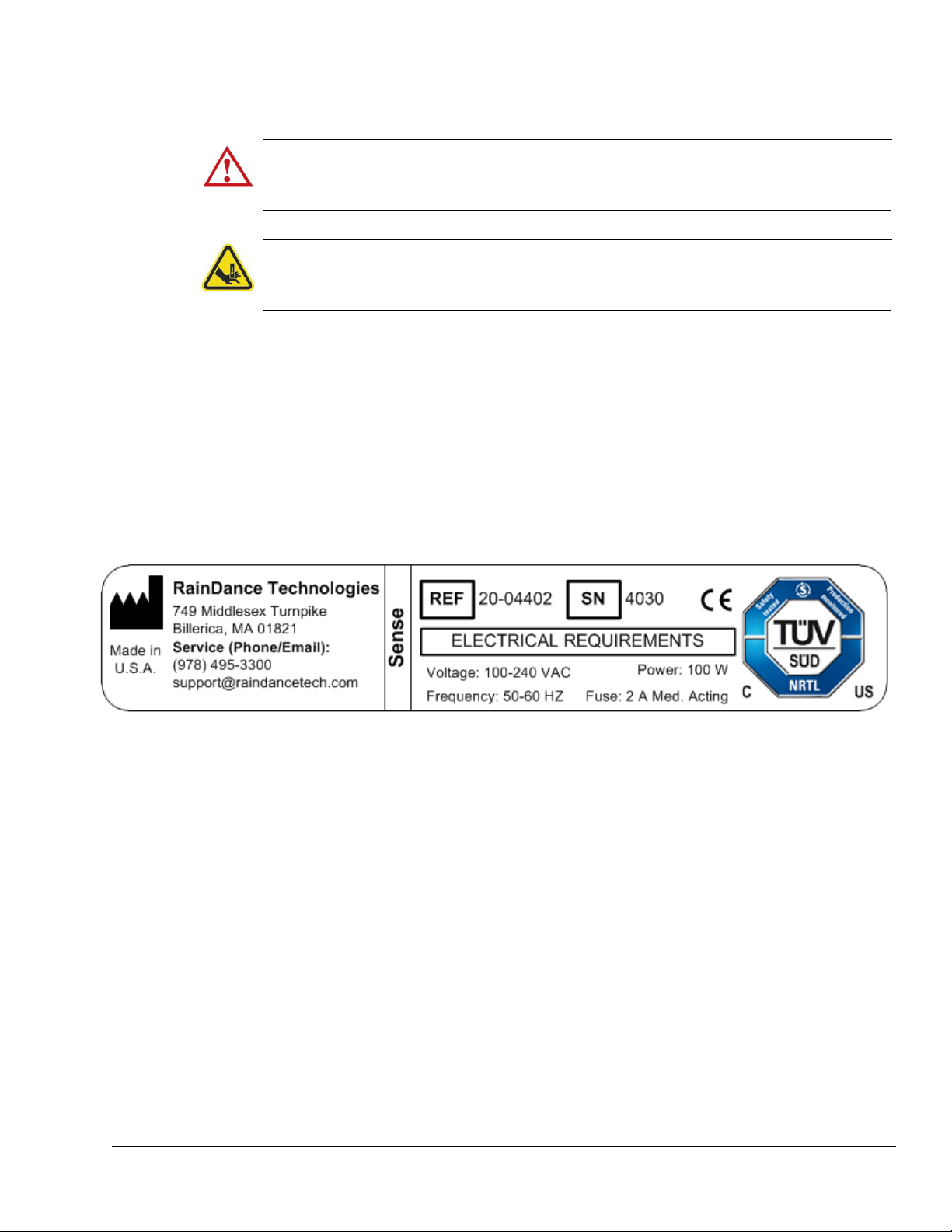
Product Labels
Figure 1-2 shows the RainDrop Sense product label.
Figure 1-2: RainDrop Sense Product Label
Safety Interlock
The RainDrop Sense is equipped with an automatic safety interlock, which prevents it from
operating unless its door is properly closed.
Packing and Transport
RainDance provides initial shipping and installation. If you are considering moving the
RainDrop Sense instrument within your laboratory, refer to Chapter 3 for the space
requirements. Do not move the instrument without assistance from
LCN 50-04344 Rev. D 1-8
RainDance Technologies.
Page 14

Chapter 1:
CHAPTER 2
Chapter 2:
Introduction
This chapter covers the following topics:
RainDrop® System Overview page 2-2
RainDrop System Major Components page 2-2
RainDrop Sense Major Components page 2-3
RainDrop Sense Layout page 2-4
RainDrop Carrier and Drive Oils page 2-4
RainDrop Sense Barcode Reader page 2-5
RainDrop Sense Chip page 2-6
2
Handling the Sense Chip page 2-6
RainDrop Sense Chip Compression Plate page 2-7
Specifications page 2-8
LCN 50-04344 Rev. D 2-1
Page 15
RainDrop Sense Operator’s Manual
RainDrop® System Overview
The RainDance RainDrop® System comprises two instruments: the RainDance Source and
the RainDrop Sense.
RainDrop System Major Components
RainDance Source Instrument
RainDrop Sense Instrument
Two Instrument Control (IC) Workstations (computers), one for each instrument
Two Instrument Control (IC) Monitors, one for each instrument
Instrument Control Cables and Peripherals
IC Workstation Power Cables
IC Monitor Power Cables
IC Keyboards
IC Mouses
IC USB Cables
Instrument Control Software (ICS)
RainDrop Analyst II™ Software
Figure 2-1: RainDrop System Major Components
LCN 50-04344 Rev. D 2-2
Page 16
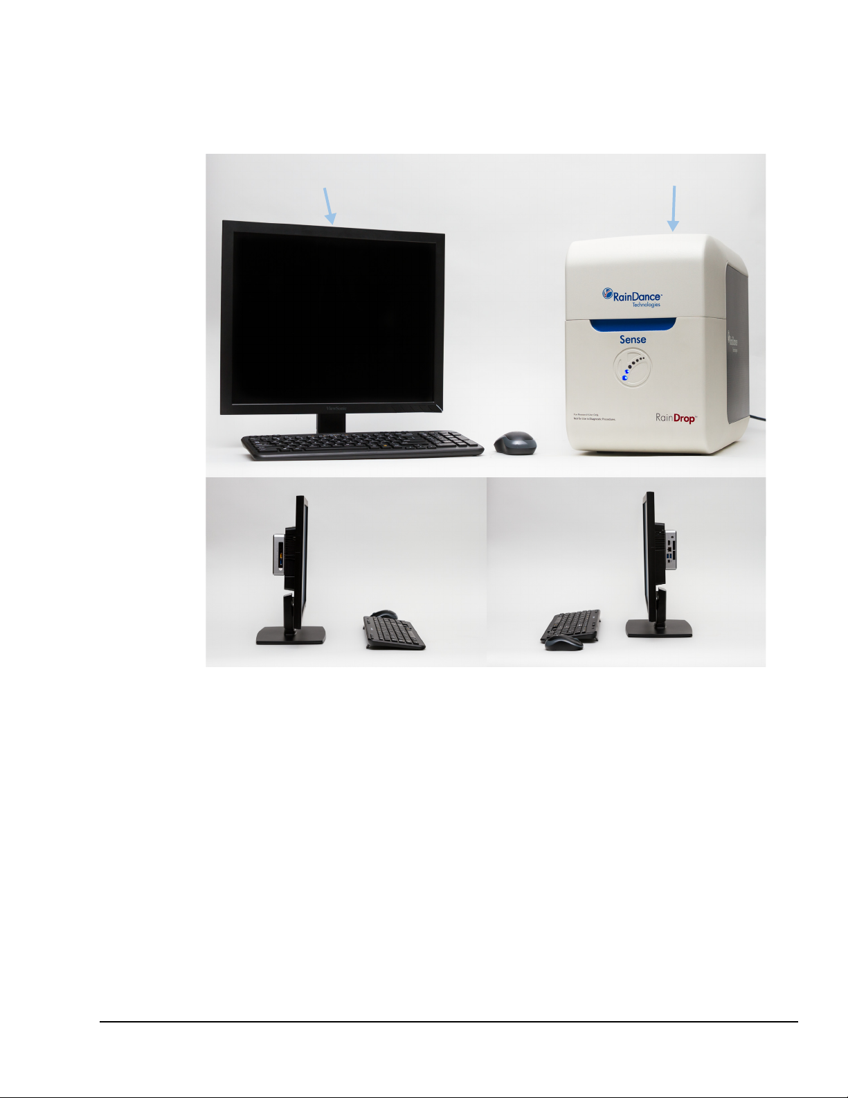
RainDrop Sense Operator’s Manual
Instrument control workstation monitor RainDrop Sense instrument
RainDrop Sense Major Components
Figure 2-2 shows the major components of RainDrop Sense instrument.
Figure 2-2: RainDrop Sense Major Components
LCN 50-04344 Rev. D 2-3
Page 17
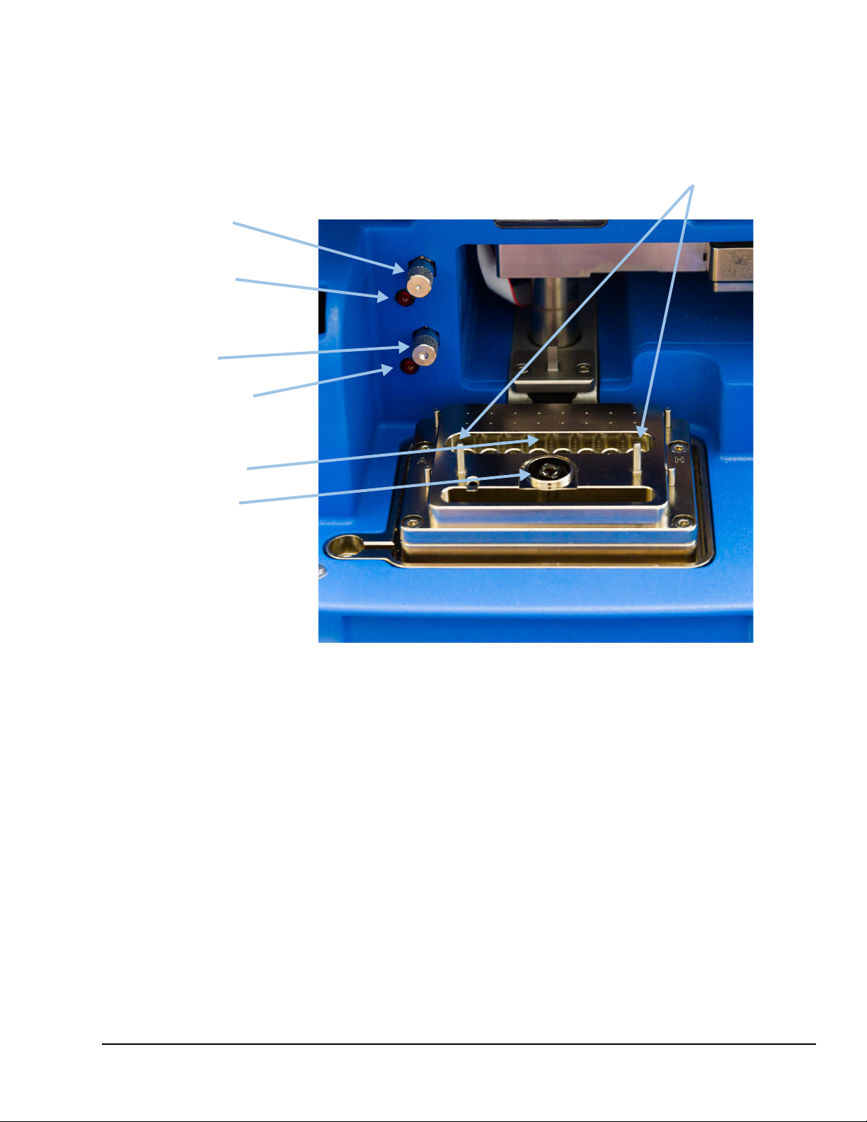
RainDrop Sense Layout
Chip alignment pins
Tube strip nest
Objective lens
Carrier oil
reservoir fill port
Carrier oil low
indicator light
Drive oil reservoir
fill port
Drive oil low
indicator light
Figure 2-3 shows the RainDrop Sense layout and oil reservoir fill ports.
RainDrop Sense Operator’s Manual
Figure 2-3: RainDrop Sense Layout
RainDrop Carrier and Drive Oils
Aqueous samples are encapsulated within each droplet on the Source instrument,
surrounded by an immiscible carrier oil. The droplets are stabilized with surfactants allowing
for robust manipulation both on and off the chip. Precise control of carrier and drive oil flow
rates on the Sense instrument allows for control of droplet spacing. Use only RainDancesupplied oils to avoid damage to the RainDrop System. The carrier oil and drive oil ports can
be filled with the oil provided in the Carrier Oil Syringe.
LCN 50-04344 Rev. D 2-4
Page 18
RainDrop Sense Barcode Reader
The barcode reader is used to scan barcodes that identify the various components used in
the RainDrop Sense (see Figure 2-4). The following lists the components to be scanned:
RainDrop Sense Chip(s)
RainDrop Carrier Oil
Tube Strips (May have a user-generated barcode. Scanning tube strips is optional.)
Items bearing a user-generated barcode for sample tracking (within the limits of
supported barcode formats)
RainDrop Sense Operator’s Manual
Figure 2-4: RainDrop Sense Barcode Reader
Scanning Barcodes
Scan items as follows:
1. Click Sc
2. Hold
the barcode, it automatically fills in the barcode information. The ICS accepts a
barcode in the 2D Data Matrix format, which allows up to 96 characters of text. You
may hear a subtle beep tone from the instrument when the barcode is accepted. If the
scanner does not read the barcode, the ICS software displays a message and allows
you to enter the barcode manually.
LCN 50-04344 Rev. D 2-5
an in the ICS software. The red scanner light pulses for 10 seconds.
the barcode on the item in front of the barcode reader. When the scanner reads
Page 19
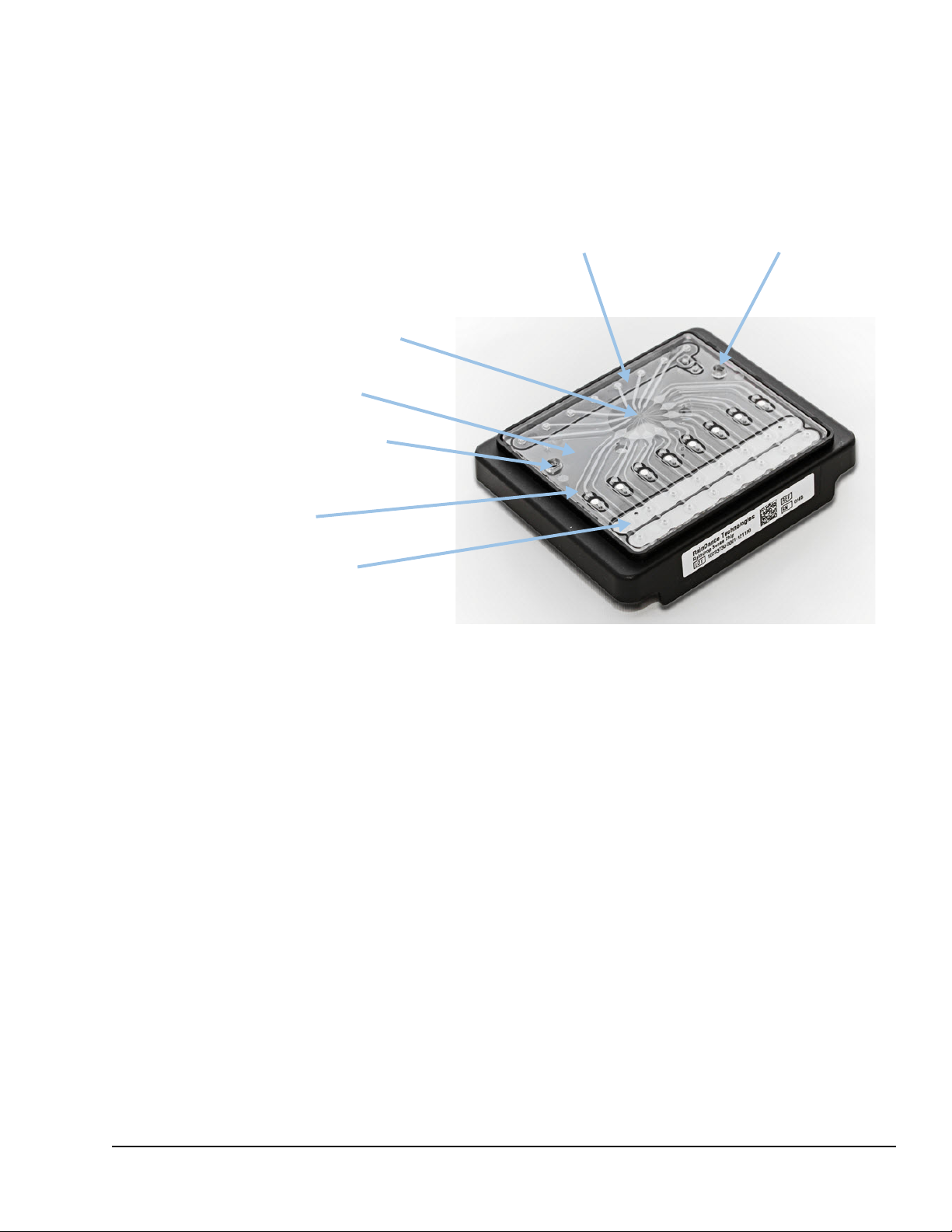
RainDrop Sense Chip
Microfluidic chip
Droplet detection
region of interest (ROI)
Fluid lanes
Chip alignment hole
Chip alignment holeWaste collection area
Oil input gaskets
The RainDrop Sense Chip is placed into the instrument on top of the PCR tube strip. As part
of the Sense process, the chip punctures the tube strip caps and transfers the emulsified
sample through its lanes where the Sense instrument identifies and counts the droplets.
RainDrop Sense Operator’s Manual
Handling the Sense Chip
Figure 2-5: RainDrop Sense Chip
Handle the Sense Chip as follows:
Grasp the chip by its sides.
Do not touch the clear microfluidic chip and its droplet detection region of interest.
Save the bag the chip comes in for later disposal of the chip.
LCN 50-04344 Rev. D 2-6
Page 20
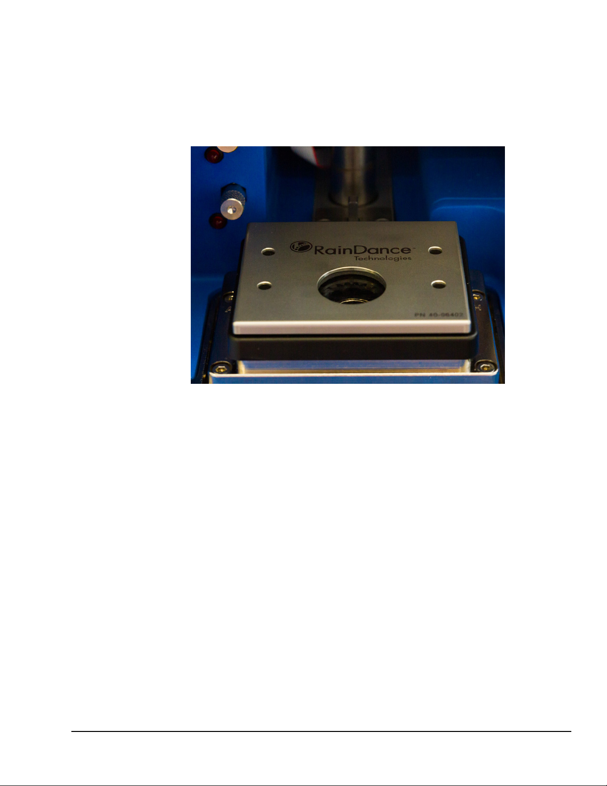
RainDrop Sense Chip Compression Plate
The RainDrop Sense Compression Plate is needed for smooth operation of the RainDrop
Sense Instrument. Position the plate over the Sense chip prior to start of the run. When the
plate is properly positioned, its RainDance logo should be facing you, the plate should be flat,
and it should not be movable left to right or front to back.
RainDrop Sense Operator’s Manual
Figure 2-6: RainDrop Sense Chip Compression Plate
LCN 50-04344 Rev. D 2-7
Page 21

Specifications
Table 2-1 shows the specifications for the RainDrop Sense instrument. Table 2-2 shows the
specifications for the Instrument Control (IC) Workstation.
Table 2-1: RainDrop Sense Hardware Specifications
Requirement or
Spec
ification Description
RainDrop Sense Operator’s Manual
Width
Depth 17 inches (43.2 cm)
Height
Weight ~65 lbs (~29 kg)
Power Source (Electrical) Voltage: 100 to 240 VAC, 35 W max
Clearance 2 inches (5 cm) in rear
Fuses 2 fuses, 2 Amperes Medium Acting
Cable Connections USB: 1 USB 3.0 and 1 USB 2.0
Required compressed gas
input pressure range at the
instrument
Capacity 8 lanes per chip
Maximum Sample
Throughput per 8 hour shift
11 inches (27.9 cm)
15 inches (38.1 cm)
1 standard grounded outlet, within 6 ft (2 m) of the
instrument
90-120 PSI (0.62 MPa – 0.82 MPa)
24 samples per shift in Standard Mode
56 samples per shift in Fast Mode
Detection Time ~8 lanes in 4 hours for Standard Mode (for 25 µL
sample)
~8 lanes in < 2 hours for Fast Mode (for 25 µL sample)
Droplet Identification Precise control of relative pressure and oil flow rate
creates ideal spacing of the thermal cycled emulsion to
allow for proper droplet identification and analysis.
Droplet Processing Droplets are processed on a chip that has no moving
parts or valves. Samples have minimal contact with
either walls or air. In addition, one-time-only chip use
prevents sample cross-contamination.
LCN 50-04344 Rev. D 2-8
Page 22

RainDrop Sense Operator’s Manual
Table 2-2: Instrument Control (IC) Workstation Specifications
Requirement or Specification
Instrument Control (IC) Workstation
Power Voltage: 100-240 VAC
Dimensions Width: 1.36 inches (3.45 cm)
Weight
Clearance 2 inches (5 cm) in rear
Network Connection
Description
Intel Computer: 19 V, 65 W
Standard grounded outlet within 6 ft (2 m) of the
instrument
Depth: 4.41 inches (11.20 cm)
Height: 4.59 inches (11.66 cm)
1.4 lb (520 g)
TCP/IP connectivity (i.e., Internet) using a standard
Ethernet connector. Instruments must be placed near
an active Ethernet port so the computers can be
networked. The Instrument Control Software has the
ability to email notifications to customers if it is
networked. In addition, RainDance has software that
allows us, with customer permission, to access the
computers to look at log files to assist in
troubleshooting and to assess instrument performance.
Without Internet access, support is compromised.
Instrument Control (IC) Monitor
Power Voltage: 100 to 240 VAC
View Sonic Monitor: 22 W max, 20 W typical
grounded outlet within 6 ft (2 m) of the instrument
Dimensions Width: 16.4 inches (41.62 cm)
Depth: 7.8 inches (19.91 cm)
Height: 15.8 inches (40.22 cm)
Weight
Clearance 0.5 inches (1.2 cm) in all directions
6.6 lb (3.0 kg)
LCN 50-04344 Rev. D 2-9
Page 23
Table 2-3: Operating Environmental Requirements
RainDrop Sense Operator’s Manual
Requirement or Specification
Laboratory Ambient
Temperature Range
Ambient Temperature
F
luctuation
Relative Humidity 5-85% RH, non-condensing
Atmospheric Pressure
Safety Compliance IEC 61010-1:2010, the international safety standard for
Data Backup RainDance suggests using a standard backup
Description
15-30°C
<0.3°C per minute
101-81 kPa (1010-810 mbar) or sea level to 1800 m
laboratory equipment, including USA (UL), Canadian
(CSA), and European (CENELEC/EN) differences
dure for any computer system.
proce
LCN 50-04344 Rev. D 2-10
Page 24

Chapter 1:
CHAPTER 3
Chapter 3:
Installation and Setup
This chapter covers the following topics:
Space Requirements page 3-2
Connecting RainDrop Sense and Instrument Controller page 3-3
Connecting Cables to the RainDrop Sense Instrument page 3-3
Connecting Cables to the Instrument Controller page 3-4
Gas Pressure Quality page 3-7
Starting Up the RainDrop Sense Instrument page 3-8
Relocating RainDrop page 3-9
3
Important: Only train
RainDrop
®
Sense instrument from its packaging and install it.
ed and certified RainDance Service Representatives may remove the
LCN 50-04344 Rev. D 3-1
Page 25
Space Requirements
Caution: The RainDrop Sense instrument is sensitive to vibration and should be
placed on a bench top that is free from vibration.
The RainDrop® Sense instrument is designed to be placed on a standard laboratory bench.
The Instrument Controller (IC) Workstation can be located on either the left or right side of the
instrument.
Table 3-1: RainDrop Sense Dimensions (Including the IC Workstation)
Minimum Height (door open) 28 inches (71.1 cm)
RainDrop Sense Operator’s Manual
Minimum Depth
Bench Loading Weight 73 lb (26.4 kg)
Minimum Width 29 inches (74 cm)
Note: Refer to
Gas Connectivity
Gas source should be located in proximity to the instrument because the gas supply
connection is located on the back of the instrument. Use 4mm OD polyurethane tubing with
an in-line shutoff valve. See Appendix A for information on suppliers.
19 inches (48.3 cm)
the Pre-Site Guide for any additional installation details.
LCN 50-04344 Rev. D 3-2
Page 26
RainDrop Sense Operator’s Manual
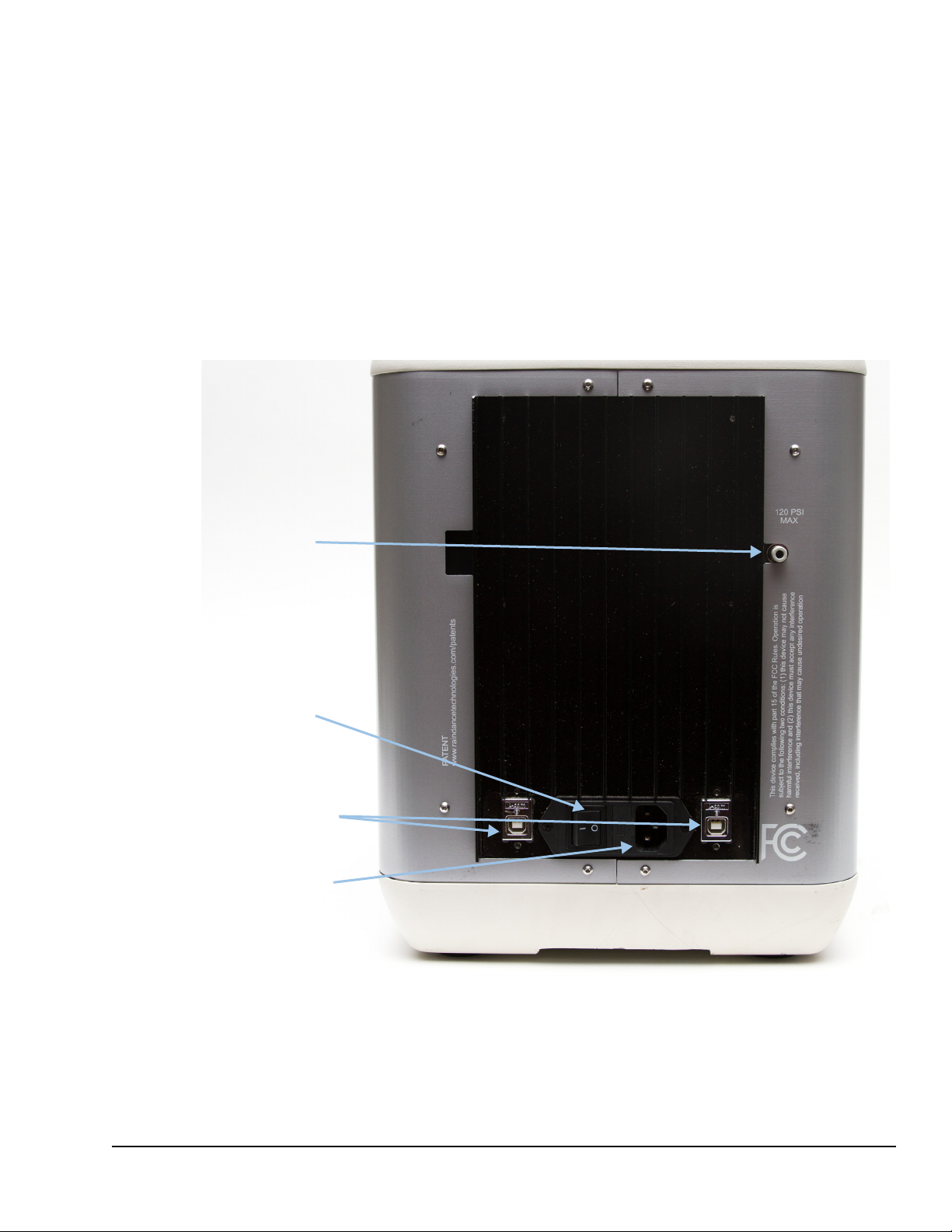
Power switch
AC power
cable
Gas pressure
USB connections
Connecting RainDrop Sense and Instrument Controller
Before powering on the RainDrop Sense instrument and its IC Workstation, make sure all
cables are properly connected as described in “Connecting Cables to the RainDrop Sense
Instrument” on page 3-3 and “Connecting Cables to the Instrument Controller” on page 3-4.
Connecting Cables to the RainDrop Sense Instrument
The RainDrop Sense instrument has three cable connections (AC Power Cable and two
USB) and a gas pressure connection as shown in Figure 3-1.
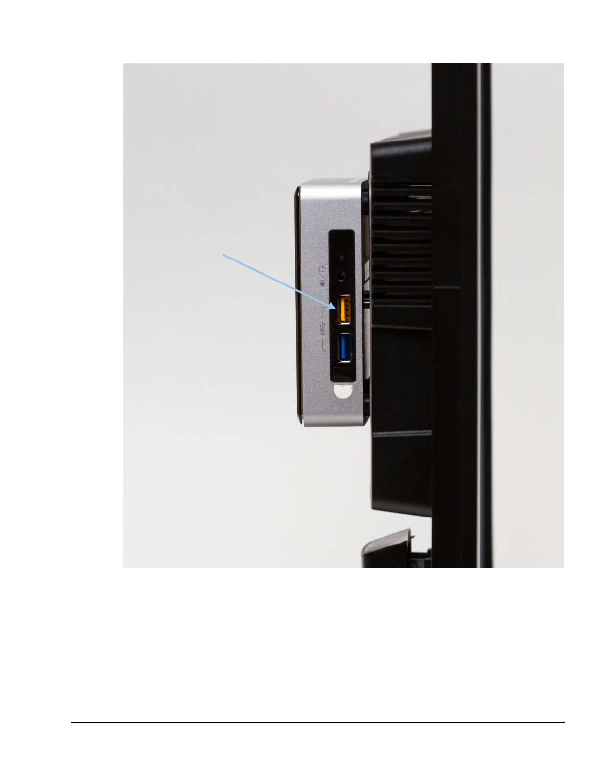
Figure 3-1: Cable Connections on RainDrop Sense
LCN 50-04344 Rev. D 3-3
Page 27

RainDrop Sense Operator’s Manual
To plug cables into the back of the Sense instrument:
1. Plug one end of the AC Power Cable into the Power Cable Connection and the other
end into a standard grounded wall outlet.
Important: The Detachable Main AC Power Cable for North America or other
countries with 120 VAC 50/60 Hz supply voltage provided for the RainDrop Sense
instrument is a 3-wire cord, 18 AWG, 10 A, 125 VAC. Never substitute a Detachable
Main AC Power Cable with a lower current or voltage rating.
2. Plug the two USB Cables into the USB Connections on the Sense instrument as
shown in
Figure 3-1.
Connecting Cables to the Instrument Controller
The RainDrop IC Workstation has USB connections used for:
The mouse
The keyboard
The RainDrop Sense instrument
Both the Source and Sense instruments connect to their IC Workstations via USB
connections.
Figure 3-2 illustrates the USB cable connections on the IC Workstation.
Note: It is important that all the USB cables on the instruments are connected to USB ports
on the workstations. Failure to connect the USB cable correctly can result in a loss of
communication with the RainDrop instrument. In addition, the USB connections on your
workstation may differ from those shown in
Figure 3-2.
LCN 50-04344 Rev. D 3-4
Page 28
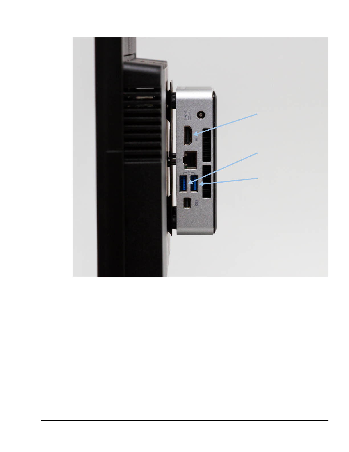
RainDrop Sense Operator’s Manual
USB port that connects to
the left output from the
Sense
USB port that connects to
the right output from the
Sense
HDMI port that connects to
the monitor
The left USB/output connects to the USB port furthest from the gas inlet and the right USB/output
Figure 3-2: Cable Connections to the IC Workstation
connects to the other available USB port.
LCN 50-04344 Rev. D 3-5
Page 29
RainDrop Sense Operator’s Manual
USB receiver
LCN 50-04344 Rev. D 3-6
Figure 3-3: USB Receiver
1. With the IC Workstation turned off, plug the USB receiver for the keyboard and mouse
into the IC Workstation.
2. Plu
3. Plu
g the right USB output from the Sense instrument into the right USB in Figure 3-2.
g the left USB output from the Sense instrument into left USB in Figure 3-2.
Page 30
Gas Pressure Quality
You may use compressed argon or nitrogen. Ensure that the compressed gas system you
use meets the following standards.
RainDrop Sense Operator’s Manual
The input pressure must be regulated to a value, at the system, within the
120 psi.
In addition, the quality must meet the ISO/DIS8573 compressed gas qu
Class 2 for instrument quality gas, as follows:
Table 3-2:
Oil (ppm) 0.1
Water (dew point)
Dirt (µ) 1.0
GasPressure Quality
-40°F
ality standard,
range of 90-
LCN 50-04344 Rev. D 3-7
Page 31

RainDrop Sense Operator’s Manual
Starting Up the RainDrop Sense Instrument
Use the following startup sequence for the RainDrop Sense instrument:
1. With the
have been connected properly as described in “Connecting Cables to the RainDrop
Sense Instrument” on page 3-3 and “Connecting Cables to the Instrument Controller”
on page 3-4.
2. T
urn on the IC Workstation (on the top of the workstation).
3. Lo
g on to the Windows 7 operating system using the RDT account.
Note: Logg
User name = RDT
No password
4. T
urn on the RainDrop Sense instrument (located on the back of the instrument).
5. W
ait 1 minute for the RainDrop Sense instrument to perform internal initialization. As
the instrument initializes, the lights on the panel illuminate to indicate its status (see
Figure 3-4).
RainDrop Sense and IC Workstation turned off, ensure that all the cables
ing on using any other account results in ICS failures.
Figure 3-4: RainDance LED Lights
6. Launch the Instrument Control Software (ICS) application as described in Chapter 4.
Table 3-3 lists the LED lights that indicate the status of the instrument.
Table 3-3: LED Lights Within the RainDance Logo
LED Name and Illumination Pattern Meaning
LCN 50-04344 Rev. D 3-8
Page 32

RainDrop Sense Operator’s Manual
Caution: The RainDrop Sense instrument weighs approximately 65 lbs (29 kg). To
avoid injuries and damage to the instrument, do not move it without assistance from
RainDance Technologies. If you want to move your instrument either within your
laboratory or to another location, contact RainDance Technologies.
Table 3-3: LED Lights Within the RainDance Logo
Main Power LED (Solid) Instrument is powered on.
All LEDs except Main Power are rotating
and off.
on
All LEDs are flashing simultaneously. Instrument has detected an error.
All LEDs are on.
All LEDs except Main Power are off. Instrument is disconnected from the ICS.
Relocating RainDrop
Instrument is operating normally.
Instrument is connected to the ICS.
LCN 50-04344 Rev. D 3-9
Page 33

Chapter 1:
CHAPTER 4
Chapter 4:
Launching the Instrument Control Software (ICS)
This chapter covers the following topics:
Introduction page 4-2
The Microsoft Windows 7 Login page 4-2
Starting the ICS Application page 4-2
ICS Login Levels page 4-3
Changing the ICS Password page 4-5
4
The ICS Account Types page 4-6
ICS Initialization page 4-7
Status Indicators page 4-10
Using Tabs in the ICS page 4-11
Navigating Through the Tabs page 4-12
Canceling a Process page 4-12
Completing a Process page 4-13
Using Scan Buttons page 4-13
Alarms, Log, and Status Tabs page 4-14
LCN 50-04344 Rev. D 4-1
Page 34

Introduction
The Instrument Control Software (ICS) application controls the operation of the RainDrop®
Sense.
The Microsoft Windows 7 Login
The Instrument Control Workstation is configured with a single Microsoft Windows 7
Operating System login. Do not edit this account or add additional accounts. Failure to
comply will result in ICS failures. The default login is an administrative account. The system
differentiates between upper and lower case characters.
RainDrop Sense Operator’s Manual
Note: Do not
use the RainDance Support Windows Logon. This will result in ICS failure.
Starting the ICS Application
The startup sequence works as follows:
1. Power on
Power on the IC Controller and log in to Windows.
Power on the RainDrop Sense. Wait one minute.
2. Click the ICS icon on
Note: You can also start the ICS application by selecting Windows 7 Start Program Menu,
and then selecting Start > All Programs > RainDance Technologies > Launch ICS.exe.
each component of the RainDrop Sense in the following sequence:
your desktop:
Note: The
designated application and software uses.
LCN 50-04344 Rev. D 4-2
IC Workstation must be dedicated to ICS Operation. Use it only for RainDance
Page 35

RainDrop Sense Operator’s Manual
The Login window opens (see Figure 4-1).
Figure 4-1: Login Window
3. Enter your Login information in the appropriate fields. Enter the Username followed by
the Password and then click Login. See ICS Login Levels for more information.
Note: Microsoft
application, both usernames and passwords are case sensitive.
ICS Login Levels
The ICS application supports two levels of access to the ICS program: User and
Administrator. The ICS application is configured with two default login IDs: one for User and
one for Administrator. RainDance recommends that you change the default password on
each of these accounts after initial use.
Table 4-1: ICS Default User and Administrator Login Information
Requirement or Specification Description
User Login Username User
User Login Password
Administrator Login User Name Admin
Administrator Login Password admin
Windows 7 usernames are not case sensitive, but passwords are. In the ICS
user
LCN 50-04344 Rev. D 4-3
Page 36

Caution: After three failed attempts to login with the wrong password, the ICS
application locks the account. You will not be able to login to your account. If this
happens, you must contact someone in your facility with an Administrator account
who can either unlock or reset your password. For details, see “Resetting Password
or Unlocking an Account” on page 6-7.
Figure 4-2 shows the message for a failed login.
RainDrop Sense Operator’s Manual
Figure 4-2: Invalid Username Message
LCN 50-04344 Rev. D 4-4
Page 37

Changing the ICS Password
This section describes how to change an ICS password. RainDance recommends that you
change the default User and Administrator passwords after initial use.
RainDrop Sense Operator’s Manual
1. Select Chan
(Figure 4-3).
2. Enter the old password in the Old Password field, the new password in the New
Password field, and the new password again in the Verify Password field. Click Save
when you are done to save the new password. Click Cancel to dismiss the dialog
without saving your changes.
ge Password from the Home menu. The Change Password dialog opens
Figure 4-3: Change Password Window
LCN 50-04344 Rev. D 4-5
Page 38

The ICS Account Types
Your account type defines the features you have access to (User and Administrator) within
the ICS application.
Table 4-2: ICS Account Type
RainDrop Sense Operator’s Manual
Feature User
Change Passwords X X
Export Instrument Files X
View Runs X X
Maintenance Actions
Add New Users X
Edit Users
Reset Passwords X
Unlock Passwords
Start Runs X X
Stop Runs X X
The pull-down menu selections differ depending on your access righ
different for a User and an Administrator account.
Administrator
X
X
X
X
ts; they are slightly
LCN 50-04344 Rev. D 4-6
Page 39

ICS Initialization
When you login to the instrument, the Initialization screen appears (see Figure 4-4).
RainDrop Sense Operator’s Manual
Figure 4-4: Initialization Screen
From the Initialization screen, click Start Initialization to initialize the system. A progress bar
shows the progress of the initialization.
Figure 4-5: Initialization Progress Bar
LCN 50-04344 Rev. D 4-7
Page 40

RainDrop Sense Operator’s Manual
If initialization fails, the following message appears:
Figure 4-6: Initialization Failure Message
Click OK and contact RainDance Support. See “RainDance Support” on page 1-3.
This error is often the result of starting ICS right after you turn on
recommends the following steps:
1. Exit the
2. T
urn the instrument off.
3. T
urn the instrument back on.
4. W
ait 1 minute.
5. Start t
ICS.
he ICS.
If the message appears again, restart the ICS.
the instrument. RainDance
LCN 50-04344 Rev. D 4-8
Page 41

RainDrop Sense Operator’s Manual
If initialization is successful, the ICS home page is displayed (see Figure 4-7).
Note: All
menu items are inactive until the initialization is finished.
Figure 4-7: Home Page
From the home page, you can Setup a Run (see Chapter )
You can perform additional tasks by ma
View Runs (see Chapter 6)
Maintenance Actions (see Chapter 7)
Add New Users (Administrator only) (see Chapter 6)
Edit Users (Administrator only) (see Chapter 6)
king selections from the drop down menus:
LCN 50-04344 Rev. D 4-9
Page 42

Status Indicators
A common set of status indicators appears throughout the system indicating the status of an
item or process being performed. In general, the green check mark (
everything is working as expected and you can proceed. The orange exclamation point (!)
indicator is a warning that means that you can continue, but that some optional fields are
blank. The red X indicator means there is a problem that needs to be resolved before you can
continue.
RainDrop Sense Operator’s Manual
?
) indicator means that
Table 4-3 shows the status indicators a
Table 4-3: Status Icons
Icon
Meaning
Ready – If all icons are green check marks, the system is ready to start a
run.
Warning (Run Will Proceed) – If there is one or more orange
exclamation point icons on the tabs, the run can start. These represent
optional information.
Error (Run Will Not Proceed) – If there is one or more red X icons on the
tabs, there is an issue that may prevent the run from being performed.
nd describes their meanings.
LCN 50-04344 Rev. D 4-10
Page 43

Using Tabs in the ICS
There are two tabs in the ICS that appear after you click Setup a Run: Run Data and Run
Info. To perform a run, you will need to complete some of the fields on each tab.
RainDrop Sense Operator’s Manual
To ensure that all of the steps are completed correctly, RainDrop
the right side of the tabs to indicate the state of each of the required items. As you complete
each step in the process the status icon for that step is updated. This section provides
general information on what appears on the tabs and how to complete these processes.
Details on how to complete each of these pro
descriptions assume you are familiar with how to use the tabs described h
Figure 4-8 shows an example of the Sense interface.
process are shown on the left side of the screen:
Run Data
Run Info
cesses is provided in Chapter . Those
The tabs required to complete the
provides a System Status on
ere.
Figure 4-8: Sense Tabs
Only one tab is visible at a time. The selected (or active) tab has a white background and the
inactive tab has a transparent background (Run Data is the active tab in Figure 4-8).
LCN 50-04344 Rev. D 4-11
Page 44

RainDrop Sense Operator’s Manual
To prepare for a run on the Sense instrument, you must complete the following fields in the
Sense ICS:
Run Data Tab:
Run Name
Sense Chip barcode lot and serial number
At least one selected lane (indicated by a green check mark)
In addition, before you can proceed with the run on the Sense instrument, you
must have clicked the Insert PCR Tube button to indicate that you have inserted
the closed tube strip into the instrument.
Select Standard or Fast Mode detection.
Run Info Tab:
Carrier Oil field and Drive Oil field and only if the instrument is out of one of those
oils
As you complete each tab, the software updates the System Status fo
green check mark is displayed, the item is ready to go. If an orange exclamation point is
displayed, it means that optional fields are blank. If a red X is displayed, there are errors or
missing data required for the run (see Table 4-3).
For a description of the meaning of the Status Indicators used on
system, see “Status Indicators” on page 4-10.
Navigating Through the Tabs
You can switch back and forth between the two tabs at will. Click the tab name to move to a
tab.
Canceling a Process
The Run Data tab has a red Cancel button in the lower left corner (Figure 4-8). If you click
Cancel while a
run is active, the application asks you to confirm that you want to cancel.
r various items. If the
the tabs and throughout the
Figure 4-9: Cancel Confirmation
When you click Yes, the information you entered when you started the process is deleted, the
run is canceled and you are returned to the RainDrop main screen.
LCN 50-04344 Rev. D 4-12
Page 45

Completing a Process
When you have completed each step to prepare for a run, review the System Status
indicators. Ideally, all the status indicators will be green check marks, although you can still
continue with orange exclamation points since they indicate only that optional fields are
blank. The process cannot be started if there is even one red X (error indications) on any of
the tabs.
RainDrop Sense Operator’s Manual
When you are satisfied that the steps for the process are complete
bottom right side of the Run Data tab. This starts the process on the RainDrop Sense
instrument.
Using Scan Buttons
The ICS allows you to scan barcodes to enter information into various text fields. There are
two types of Scan buttons available in the system as shown in Table 4-4.
Table 4-4: Scan Buttons
Button Description Use
, click Start Run on the
Figure 4-10: Start Run Button
Manual Scan Button The instrument requires that you
manually enter a barcode.
Scan Button The system allows you to scan any
type of barcode.
Clicking either type of scan butt
to scan the barcode.
If you scan the wrong type of barcode, an error message appears. ICS will not a
invalid barcode.
LCN 50-04344 Rev. D 4-13
on activates the barcode reader on the system and allows you
ccept an
Page 46

Alarms, Log, and Status Tabs
The Alarms, Log, and Status tabs are displayed on the bottom of the screen (see Figure 4-
11). Each of these tabs is described below.
Figure 4-11: Example of Screen Showing Alarms, Log, and Status Tab at Bottom
The Alarms tab is displayed by default. Click Log or Status to display that tab.
Alarms Tab – This tab lists instrument errors that exist in the system. If an error
appears, the system is in a warning or error state. Different errors occur during the
setup of the instrument. If an error does not clear when you close the door and click
Start Run, check “Troubleshooting” on page 7-8. If the issue is still not resolved,
contact supp
Log Tab – This tab is used for service purposes. It is used to check on the system
automation.
Status Tab – This tab is used for service purposes. It is used to determine the status of
the instrument at different points during operation.
ort@raindancetech.com for assistance.
RainDrop Sense Operator’s Manual
LCN 50-04344 Rev. D 4-14
Page 47

Chapter 1:
CHAPTER 5
Chapter 5:
Performing a Sense Run
This chapter covers the following topics:
Introduction page 5-2
Gathering Supplies page 5-2
Starting a Sense Run page 5-3
Completing the ICS Setup page 5-10
Checking the Status Indicators page 5-10
Completing the Run Data Tab page 5-12
Completing the Run Info Tab page 5-15
5
Completing the Run Tabs Using the Import Function page 5-16
Using Email Notification page 5-16
Performing the Run page 5-18
Canceling a Run page 5-20
Handling Data page 5-21
Exporting Data page 5-22
Moving Data Files page 5-23
LCN 50-04344 Rev. D 5-1
Page 48

Introduction
Perform the operations described in this chapter on the RainDrop® Sense instrument. This
procedure requires a number of consumables (available from RainDance Technologies
other manufacturers).
Note: For the list of required consumables, see “RainDrop® Consumables and Equipment”
on page A-1.
This chapter describes how to start a run on the RainDrop Sense instrument. Some of the
steps involve preparing the physical components of the system and some of them take place
within the RainDrop ICS.
For detailed information the ICS software, see Chapter 4 and Chapter 6.
Note: Extraneous clusters have been noted in 50ul samples run in the FAST mode on the
Sense instrument. For the highest quality data we recommend limiting sample volumes to
25ul if the samples are to be run in the FAST mode on the Sense instrument.
RainDrop Sense Operator’s Manual
®
and
Gathering Supplies
To start a run on the RainDrop Sense instrument, have the following equipment and supplies
available:
Gloves, nitrile or latex
Sense Chip, P/N 30-06086
Sense Chip Compression Plate, P/N 30-06423
Drive Oil, shipped in syringes, P/N 30-07117
PCR tube strip containing emulsion generated on the RainDance Source instrument
and following thermal cycling.
For Standard Mode detection, standard PCR Tube Strip Caps (P/N 40-06087)
For Fast Mode detection, High Speed Caps (P/N 40-08286)
LCN 50-04344 Rev. D 5-2
Page 49

Starting a Sense Run
This procedure assumes you have prepared your sample and that you have assembled all
the necessary equipment and supplies. It also assumes that you have completed thermal
cycling the sample. It shows you how to start a run on the RainDrop Sense instrument.
unch the ICS software for the Sense instrument and log in.
1. La
RainDrop Sense Operator’s Manual
Figure 5-1: Login Screen
2. Click Start Initialization.
Figure 5-2: Initialization Screen
When you click Start Initialization, the system automatically prepares the instrument
for normal operation. It sets valves and pressures and turns the laser in the barcode
reader off. In addition, it homes the motion control subsystem. Initialization takes
approximately four minutes.
LCN 50-04344 Rev. D 5-3
Page 50

RainDrop Sense Operator’s Manual
Note: If initialization fails, the ICS returns to the Initialization screen after about
fifteen minutes. Contact RainDance Support for assistance. See “RainDance Support”
on page 1-3.
3. Click Se
tup a Run.
Figure 5-3: Instrument Status and Setup a Run Screen
LCN 50-04344 Rev. D 5-4
Page 51

4. Select the Run Info tab.
RainDrop Sense Operator’s Manual
Figure 5-4: Run Info Tab
5. On the Run Info tab, click Open Door. The door on the Sense instrument unlocks
allowing you to lift it to the upright, open position.
6. If ru
nning in Fast Mode, use High Speed Caps. Following thermal cycling, carefully
remove the domed caps (Axygen) and replace with High Speed Caps. Rock the caps
back and forth to seat properly, then press into place. Ensure the cap is secured and
the strip is tightly covered.
A properly covered PCR tube strip has:
A flat cap all the way across
Its tab oriented to the left (over number 1 on the tube strip)
An improperly covered PCR tube strip has:
A bump or buckle
A loosely fitting cap
Its tab to right (over number 8 on the tube strip)
LCN 50-04344 Rev. D 5-5
Page 52

A bump in the cap
7. Lift the door to the fully open position.
.
RainDrop Sense Operator’s Manual
Figure 5-5: Improperly Covered PCR Tube Strip
LCN 50-04344 Rev. D 5-6
Page 53

RainDrop Sense Operator’s Manual
Figure 5-6: Sense Door in Fully Open Position
LCN 50-04344 Rev. D 5-7
Page 54

RainDrop Sense Operator’s Manual
8. Insert a tube strip into the tube strip nest (see Figure 2-3). Orient the tabbed end to the
left.
Figure 5-7: Insert a Tube Strip
9. Remove a Sense Chip from its packaging; for more information on the chip, see see
“RainDrop Sense Chip” on page 2-6. Handle the Sense Chip as follows:
With gloved hands, grasp the chip by its sides.
Do not touch the clear microfluidic chip and its droplet detection region of
interest.
Save the bag the chip comes in for later disposal of the chip.
Do not touch the objective lens.
10. Scan the
chip by clicking Scan in the ICS software. The red scanner light pulses for
10 seconds. Hold the Sense Chip in front of the barcode reader. If the scanner reads
the barcode, it automatically fills in the barcode information. The ICS accepts a
barcode in the 2D Data Matrix format, which allows up to 96 characters of text. You
may hear a subtle beep tone from the Sense instrument.
If the scanner does not read the barcode, the ICS software displays a
message and
allows you to enter the barcode manually. To do so, click the Manual button and
enter the barcode numbers from the label of the chip. In manual format, the ICS
accepts 99 characters of text.
11. In
sert the chip into the Sense instrument. Orient the Sense Chip over the alignment
pins and ensure that the pins are coming through the alignment holes on the chip. Do
not insert it at an angle. The instrument is designed so that the Sense Chip punctures
the caps of the tube strip. Do not apply pressure to the chip after inserting it. It is
important that the instrument is able to make a seal and then puncture the tube caps.
The Sense instrument will not allow you to proceed until the chip is oriented properly.
LCN 50-04344 Rev. D 5-8
Page 55

RainDrop Sense Operator’s Manual
Figure 5-8: Inserting a Sense Chip
12. Locate the Chip Compression Plate; for more information on the plate, see see
“RainDrop Sense Chip Compression Plate” on page 2-7.
13. Place t
When the plate is properly positioned, its RainDance logo should be
he Chip Compression Plate over the Sense chip as shown in Figure 5-9.
facing you, the
plate should be flat, and it should not be movable left to right or front to back.
Figure 5-9: Placing the Chip Compression Plate
After you insert the Chip Compression Plate, you are done setting up the physical
components.
14. Clo
se the door on the Sense instrument.
LCN 50-04344 Rev. D 5-9
Page 56

Completing the ICS Setup
Before starting a run on the Sense instrument, you must complete a number of setup steps.
The steps ensure that the instrument is ready for operation and provide data about the run.
They include:
Check the status of various components.
Complete the Run Data.
Complete the Run Info.
Checking the Status Indicators
Status indicators tell you about the readiness of the instrument.
RainDrop Sense Operator’s Manual
Figure 5-10: System Statuses
Observe the status indicators in the software.
Table 5-1: System Status Indicators
Indicator
Pressure
Ready
Carrier Oil
Drive Oil Indicates the status of the drive oil reservoir. When there is sufficient oil to
Meaning
Indicates the status of the instrument gas pressure. When the pressure is
sufficient, the ready indicator is displayed.
Indicates the status of the carrier oil reservoir. When there is sufficient oil
to complete a run, the ready indicator is displayed. A valid carrier oil lot
number is required for the green check mark to be displayed.
complete a run, the ready indicator is displayed. A valid drive oil lot
number is required for the green check mark to be displayed.
LCN 50-04344 Rev. D 5-10
Page 57

Table 5-1: System Status Indicators
RainDrop Sense Operator’s Manual
Chip
Inserted
Indicates the presence of the Sense Chip. When the Sense Chip is
present and inserted properly, the ready indicator is displayed.
Note: You must scan the chip prior to use; otherwise, the instrument will
not detect it. If you have scanned the chip before inserting it and it is still
not detected, wiggle the chip and try again.
Door Closed Indicates the status of the instrument door. When the door is properly
closed, the ready indicator is displayed.
System
Ready
Indicates the overall status of the instrument. When all the requirements
of the instrument are present and ready for a run, the ready indicator is
displayed.
In addition to satisfying the Status Indicators, in order to start a run you must also have:
Scanned or input the barcode number from a Sense Chip
Clicked Insert Tube Strip to affirm that you have inserted the tube strip
LCN 50-04344 Rev. D 5-11
Page 58

Completing the Run Data Tab
The Run Data tab opens after you click Start Run on the startup screen and contains the
details about the contents of the run. You can enter this information manually or you can
import it from a file you saved on the Source instrument.
RainDrop Sense Operator’s Manual
Figure 5-11: Run Data Tab
Only the following fields on the Run Data tab are required for the run to proceed:
Run Name
Sense Chip barcode lot and serial number
At least one selected lane (indicated by a green check mark)
Your lab procedures determine how much of the optional information
specific situation.
In addition, before you can proceed with the run, you must have
button to indicate that you have inserted the closed tube strip into the instrument.
is necessary for your
clicked the Insert PCR Tube
LCN 50-04344 Rev. D 5-12
Page 59

Table 5-2: Run Data Fields
RainDrop Sense Operator’s Manual
Field Name
Run Name The name of the run. Run name is required and can contain up to 20
Lanes A - H
Lane
Description
Sense Chip Lot
& Serial
Number
Meaning
characters. This is required.
The identifiers for each tube (or lane) on the chip. These fields are not
required. The lane letter identifiers are hard-coded and cannot be
edited.
The text description that you enter. This is not required.
The identifiers for each Sense Chip.
completed when you scan the chip and is required.
This information is automatically
Run Filenames
When the ICS saves data at the end of a run, it uses the information you enter in the fields in
the above table to name the file. It creates one file per lane in a folder named for the Run ID,
as follows:
The filename for one lane of a run looks like this:
<Run ID>-<Lane Letter>-<Lane Description>.fcs
For example: 1302181535-A-ExampleDescription.fcs
The Run ID is the numeric run number from the upper right corner of
appears on both the Run Data tab and the Run Info tab. See “Handling Data” on page 5-21
for more information.
the ICS screen. It
Entering the Run Data
Enter the run data as follows:
1. T
ype the name of the run into the Run Name field.
2. All lan
3. If n
es are selected by default. Deselect any lanes you are not using. At least one
lane must be selected in order for the run to proceed.
ecessary, enter lane information in one of the following ways:
Type the name for the lane manually. When you enter the name manually, the field
limits entry to 99 characters.
LCN 50-04344 Rev. D 5-13
Page 60

RainDrop Sense Operator’s Manual
Scan the barcode from a printout. To do so, place the printout in front of the
barcode reader and click Scan next to the correct lane. When you enter the name
using the scanner, the field limits entry to 96 characters.
Import the lane information as described in see “Completing the Run Tabs Using
the Import Function” on page 5-16.
4. Select the number of droplets you want from the Droplet drop-down.
5. Click Insert PCR Tube to confirm that you have inserted the tube strip into the
instrument.
Note: The Sense Chip field should already display the information you scanned earlier in see
“Starting a Sense Run” on page 5-3.
LCN 50-04344 Rev. D 5-14
Page 61

Completing the Run Info Tab
The fields on the Run Info tab contain information about the run. The only fields on this tab
that are required are the Carrier Oil and Drive Oil fields and only if the instrument is out of one
of these types of oil.
RainDrop Sense Operator’s Manual
Figure 5-12: Run Info Tab
Your lab procedures determine how much of the information is necessary for your specific
situation. Enter the run information as follows:
Table 5-3: Run Info Fields
Field Name
Operator The name of the person performing the run.
PCR Tube ID
Run
Comments
LCN 50-04344 Rev. D 5-15
Meaning
The identifier of the sample to be run.
Any detailed descriptive information you want stored with the run
information.
Page 62

RainDrop Sense Operator’s Manual
Completing the Run Tabs Using the Import Function
To complete the run tabs using the import function:
1. Click Import at the top of the Run Data tab. The import works only with XML files
generated by the Source instrument. The page displays a list of runs.
2. Locate the file to import and click on it.
3. ICS imports only the following fields:
On the Run Data tab:
Run Name
Lane information
On the Run Info tab:
Operator
PCR Tube ID
Run Comments
4. Complete any other of the optional fields, as needed.
Using Email Notification
The RainDrop Sense instrument is located in a lab space which may be a distance from your
desk or usual work area. Email Notification allows you to receive messages when a run is
finished, so that you do not have to continually check the instrument. Select Send Run
Emails on the Run Info tab. If email addresses have been entered by an Administrator, they
appear in the Email Notification field. You can leave these addresses as is, edit them, or add
to them. Notifications are sent to those addresses.
Note: Email notification does not support text messaging.
Setting Up Email Notification (Administrator)
Setup Email Notification as needed. You do not have to edit these settings for each run. You
can establish email settings and then not change them unless you need to change who is
notified at the end of a run.
To enter email addresses:
1. Select Setup Email from the Actions menu. The Email dialog opens.
2. Enter email addresses in the Email Notification field, separated by semi-colons.
These email addresses will appear on the Run Info tab by default.
3. Select Send Run Emails, if you want this to be the default action.
LCN 50-04344 Rev. D 5-16
Page 63

RainDrop Sense Operator’s Manual
4. Click Save to save the new addresses. Click Close to dismiss the dialog.
Email Messages
Email messages contain the following information:
Table 5-4: Email Message Data
Field Name What is reported
RainDance ID
Run Name The name the user entered in the Run Name field prior to
Description
Start Time The date and time the run was started
End Time
Sample Info For each sample, it lists: Lane, Sample Description, Droplets,
Total Samples The number of samples attempted
Samples
Succe
Samples Failed The number of samples that generated an error, including any
Errors All errors encountered during the run
ssful
The serial number of the instrument
beginning the run. If the user does not enter a Run Name, this
lists a name provided by the RainDrop Sense instrument.
The comments entered by the user at run time, if any
The date and time the run ended
CV (coefficient of variance), Read Length, and Status
The number of samples that successfully ran without errors
samples not processed because the run was stopped because
of a prior/fatal error
LCN 50-04344 Rev. D 5-17
Page 64

Performing the Run
After you have entered the required run data, you are ready to begin the run.
RainDrop Sense Operator’s Manual
1. Click the Start Run bu
progress as shown in the following image.
tton. The screen displays information about the Sense run in
Figure 5-13: Sense Run Screen
The center of the screen displays information about which sample is being processed.
The right side of the screen displays information about the progress of the run.
2. Whe
3. Lift the
4. T
LCN 50-04344 Rev. D 5-18
n the sample is done, the door unlocks automatically.
door to its full open position.
o minimize the potential for contaminating the lab environment with the amplicon,
return the used chip to the bag it came in and discard it in a solid waste disposal
container.
Page 65

The ICS displays the Run Complete screen.
RainDrop Sense Operator’s Manual
Figure 5-14: Sense Run Complete Screen
5. Click View Run Report to review the run data.
6. Click Sa
ve and Close. ICS saves the data from the run in a file in FCS format, which
can be read by the RainDrop Analyst software.
Note:
As stated above, the instrument door unlocks after the run is complete. If you
accidentally close the door and still need access, click Open Door to open it.
LCN 50-04344 Rev. D 5-19
Page 66

Canceling a Run
If you want to stop a run after you have started filling out the Run Data tab, but before clicking
Start Run, click Cancel. This brings you back to the Instrument Status and Setup a Run
Screen (see
If you want to stop a run after clicking Start Run, click the Abort button. This brings you to the
Run Completion screen.
Figure 5-3) and blanks out any data you have entered for this run.
RainDrop Sense Operator’s Manual
LCN 50-04344 Rev. D 5-20
Page 67

Handling Data
The data from Sense runs is collected on the hard drive of the ICS Workstation. Files are
stored in folders on the D drive named for their runs within a RainDance folder as follows:
D:\RainDance\RunLogs\<RunID>
The <RunID> is displayed in the upper right corner of the ICS screen on both the Run Data
tab and the Run Info tab.
The Run ID is built on the date and time as follows: YYMMDDHHMM. In the above image, the
number 1302181529 represents 3:29 pm on February 18, 2013. The Sense ICS creates the
folder when you click Start Run.
Upon completing the run, the Sense ICS creates one FCS file per lane within the Run ID
folder. The filename for one lane of a run looks like this:
<RunID>-<Lane Letter>-<Lane Description>.fcs
For example: 1302181529-A-ExampleDescription.fcs
RainDrop Sense Operator’s Manual
The lane letter and lane description come from data you enter on the Run Data tab. See
“Completing the Run Data Tab” on page 5-12 for more information.
LCN 50-04344 Rev. D 5-21
Page 68

Exporting Data
The Export Data function allows you to search for previous runs and to save that run data to
either the same or a new location. This allows you to move your FCS files from one location
to another to make them available for use by other applications such as analysis software. To
export data:
1. La
RainDrop Sense Operator’s Manual
unch the ICS as you normally do. See “Starting the ICS Application” on page 4-2.
2. Click Export Data.
The Export Data screen opens.
Figure 5-15: Export Data Screen
3. Use the Start Date and End Date fields to specify a range for the data. Click Update
List to tell ICS to display only data that fall between the dates you enter.
4. Select o
runs or Ctrl+Click to select non-contiguous runs.
5. T
ype the name of an Export Directory or click Browse to locate a folder for the
export.
6. Click Ex
the message.
LCN 50-04344 Rev. D 5-22
ne or more runs by clicking on them. Use Shift+Click to select contiguous
port. When the export is done, ICS displays a message. Click OK to dismiss
Page 69

Moving Data Files
The data files created by the Sense instrument from just one run can easily exceed several
gigabytes. You can use the Export process described above to locate your FCS files in a
location that is accessible by your analysis software. In addition, RainDance offers the
following instructions for moving your files when disk space becomes an issue on the ICS
Workstation. Keep in mind that the network configuration at your location is unique. You may
need to seek assistance from your in-house IT department to learn their recommendations.
Because RainDrop files are large, RainDance has several recommendations for managing
your data files.
Never attempt to move files while a run is in process.
Move files at a time when network activity is at a minimum so that file transfer is as
efficient as possible.
Consider developing a file management protocol. The disk drive on the ICS is large,
but not infinite. You may need to save files to an external storage device and remove
some from the internal hard drive from time to time. Consult with your internal IT
department to develop a strategy for managing large amounts of data.
RainDrop Sense Operator’s Manual
To copy files using a flash drive:
1. Insert the flash drive into a USB port on the ICS Workstation.
2. Launch Windows Explorer and navigate to the D drive.
3. Open the RainDance folder on the D drive.
4. Open the Run folder whose data you want to copy.
5. Click the Type column to sort the data files by type. The only files you need to move to
the computer running RainDrop Analyst II are the FCS files. They should appear at the
top of the sorted list.
6. Select only the FCS files. Click and drag them to the flash drive icon within Windows
Explorer.
7. When Windows Explorer is done copying the files to the flash drive, bring the drive to
the computer running RainDrop Analyst.
To copy files over a network:
1. Launch Windows Explorer and navigate to the D drive.
LCN 50-04344 Rev. D 5-23
Page 70

RainDrop Sense Operator’s Manual
2. Open the RainDance folder on the D drive.
3. Open the Run folder whose data you want to copy.
4. Click the Type column to sort the data files by type. The only files you need to move to
the computer running RainDrop Analyst II are the FCS files. They should appear at the
top of the sorted list.
5. Select only the FCS files. Right-click on the collection of files.
6. From the pop-up menu, select Copy.
7. Navigate to the network drive where you want to copy the files.
8. Locate the folder where you want to move the FCS files. Right-click and from the pop-
up menu, select Paste.
LCN 50-04344 Rev. D 5-24
Page 71

Chapter 1:
CHAPTER 6
Chapter 6:
Managing the System
This chapter covers the following topics:
Introduction page 6-2
Managing Users page 6-2
Adding a New User page 6-3
Editing a User page 6-5
Deleting a User page 6-7
Resetting Password or Unlocking an Account page 6-7
Viewing Past Runs page 6-8
6
Viewing Runs page 6-8
LCN 50-04344 Rev. D 6-1
Page 72

Introduction
You must have a username and password before you can login to the ICS application. There
are two types of user accounts: Administrator and User. Chapter 4 provides detailed
information on logins and account types.
RainDrop Sense Operator’s Manual
Important:
This chapter describes several soft
Managing Users
Viewing Past Runs
To manage users, you must be logged in with Administrator privileges.
Managing Users
The ICS software lets you manage user accounts from the Actions menu (see Figure 6-1).
ware management functions. These include:
Figure 6-1: Actions Menu
LCN 50-04344 Rev. D 6-2
Page 73

Adding a New User
To add a new user:
RainDrop Sense Operator’s Manual
1. From the Ac
The Add New User dialog
tions menu, select Add New User (see Figure 6-1).
opens (see Figure 6-2).
Figure 6-2: Add New User Dialog
2. Enter the information for the new user as required (see Table 6-1) and click Add to
save it or Cancel to dismiss the dialo
LCN 50-04344 Rev. D 6-3
g without saving your entries.
Page 74

Table 6-1: Add New User Dialog
RainDrop Sense Operator’s Manual
Field or Table Element
User Name Specifies the name you use to login. Case sensitive.
Password
First Name, Last Name Specifies the user's first and last names. Required.
Email Address
Address Specifies the user's address. Required.
Contact Number
Privilege Specifies the user's Privilege level (Admin or User)
Add, Cancel buttons Adds the user information, or cancels the process. If
Description
Required.
Specifies the password; any alphanumeric combination
is acceptable. Case sensitive. Required.
Specifies the user's email address. Required.
Specifies the user’s phone number. Required.
selected from a drop-down menu. Required.
added
successfully, a confirmation window displays.
LCN 50-04344 Rev. D 6-4
Page 75

Editing a User
The Edit Users dialog allows a user with administrator privileges to edit the information for an
existing user or remove an existing user from the database. An administrator can also add a
new user from this dialog.
RainDrop Sense Operator’s Manual
1. From the Ac
opens (see Figure 6-3).
tions menu, select Edit Users (see Figure 6-1). The Edit Users dialog
Figure 6-3: Edit Users Dialog Box
LCN 50-04344 Rev. D 6-5
Page 76

RainDrop Sense Operator’s Manual
2. To edit the data for an existing user, click Edit in the row for that user. The Edit User
Information dialog opens for the selected user (see Figure 6-4).
Figure 6-4: Edit User Dialog Box
3. Editing user information is essentially the same as adding new user information. Edit
the user information as required (see Table 6-1) and th
en click Save. Click Cancel
button to dismiss the dialog without saving any changes.
LCN 50-04344 Rev. D 6-6
Page 77

RainDrop Sense Operator’s Manual
Deleting a User
To delete a user:
1. Select Edit Users from the Actions menu (see Figure 6-1). The Edit Users dialog
opens as in Figure 6-3.
2. Click Remove in the same row as the user to be deleted. The system asks you to
confirm that you want to delete the user. Click Yes to confirm or No to cancel the
deletion.
Resetting Password or Unlocking an Account
After three failed attempts to login with the wrong password, the ICS application locks the
account and you are not able to login. If this happens, you must contact someone in your
facility with Administrator privileges who can either reset or unlock your password.
To reset an account:
1. Select the Reset Password check box in the Edit User dialog (see Figure 6-4). This
changes the user's password to the default password, abc123.
2. To save the changes to the account, click Save. The application displays a message
confirming that the changes have been saved.
To unlock an account:
1. Select the Unlock Account check box in the Edit User dialog (see Figure 6-4). This
allows the user to login again with his/her original password.
2. To save the changes to the account, click Save.The application displays a message
confirming that the changes have been saved.
LCN 50-04344 Rev. D 6-7
Page 78

Viewing Past Runs
This section describes how to view previous runs. It also describes how to generate and view
reports and how to export run results.
Viewing Runs
Certain run parameters are saved by the ICS application. The ICS application lets you search
for and view past run parameters by entering a specific Start Date and an End Date
(inclusive) on which the run was completed.
To view a run report:
RainDrop Sense Operator’s Manual
1. Select V
iew Runs from the Actions menu (see Figure 6-1). The View Run Report
window opens (see Figure 6-5).
Figure 6-5: View Run Report Window
2. Enter a date range to locate the run of interest and click Search. The default start and
end dates are today’s date, so if you want to see the run you just completed, you can
just click Search without changing the date.
All runs that match the selected date range appear in a list below the white title b
LCN 50-04344 Rev. D 6-8
ar.
Page 79

RainDrop Sense Operator’s Manual
3. Clicking or selecting a row in the list of runs opens the report for that run. This may
take 2-5 seconds.
Figure 6-6: Example of a Sense Run Report
Reports are divided into three sections. The first section contains:
Run Name
Operator
RainDance ID (machine name)
Tube Strip
The second section contains a summary of how the run performed. It
Channel Pass/Fail
Sample Information
The last section lists the following:
Start Time
End Time
Chip Lot
Chip Serial Number
Carrier Oil Lot
Drive Oil Lot
Run Comments
includes:
LCN 50-04344 Rev. D 6-9
Page 80

RainDrop Sense Operator’s Manual
4. From the menu bar (see Figure 6-7) you can print the report or export it to various
formats, such as a PDF file or an Excel file.
Figure 6-7: Report Menu
5. When you are done viewing the report, close it by clicking on the Close box in the
upper right corner of the screen. You return to the View Runs window so you can view
additional reports if necessary.
LCN 50-04344 Rev. D 6-10
Page 81

Chapter 1:
CHAPTER 7
Chapter 7:
Support, Customer Maintenance, and Troubleshooting
This chapter covers the following topics:
RainDance Support page 7-2
RainDance Planned Maintenance page 7-2
Customer Maintenance page 7-2
Restarting the IC Workstation page 7-2
Cleaning the RainDrop Sense page 7-2
7
Refilling the Oil Reservoir page 7-3
Service and Diagnostic Requirements page 7-6
Powering Off the System page 7-6
Powering On or Restarting the System page 7-6
Restoring the System After a Failure page 7-6
Support Agreement Information page 7-7
Moving the System page 7-7
Storing the System page 7-7
Reinstalling/Updating ICS Application page 7-7
Error Messages page 7-7
Troubleshooting page 7-8
LCN 50-04343 Rev. D 7-1
Page 82

Maintenance refers to non-technical procedures you must perform to keep the system
working properly. Service refers to tasks that are intended to be performed only by a qualified
RainDance-authorized service representative. The RainDrop® System comprises two
instruments: RainDance Source and RainDrop Sense. The sections in this chapter describe
them separately only when each instrument requires different maintenance or service.
RainDance Support
RainDrop Sense Operator’s Manual
RainDance Technologies
Some troubleshooting information is provided within this chapter (see
“Troubleshooting” on page 7-8.). Additional self-service technical and troubleshooting
information is available at www.raindancetech.com/support.
To request technical assistance from RainDance support personnel, send an email to
support@raindancetech.com.
®
provides full support for their products.
RainDance Planned Maintenance
A Planned Maintenance (PM) schedule and tasks are designed to be performed by
RainDance Support personnel. A number of PMs are conducted as part of the service
contract agreement. Contact RainDance Support for a recommended PM schedule.
Customer Maintenance
This section lists the steps you should follow for proper maintenance of the RainDrop Sense
system.
Restarting the IC Workstation
Good operating practice for any Windows operating system includes restarting the operating
system on a weekly basis. To perform a shutdown, select the Start icon the lower left corner
of the screen and select Shut down. When the system has completed its power off routine,
reboot the Windows 7 operating system on the IC Workstation as described in
or Restarting the System” on page 7-6.
“Powering On
Cleaning the RainDrop Sense
There is no extraordinary routine maintenance required for the RainDrop instruments. Clean
the chip dock of spills and residues as follows:
Always use protective gloves.
Use only a soft, lint-free towel to clean the chip dock; wet with either isopropanol or
HFE-7100.
For DNA decontamination, RainDance recommends using HFE-7100 or DNA-
ExitusPlus.
LCN 50-04343 Rev. D 7-2
Page 83

Keep cleaning fluids away from the objective lens.
Caution: Use caution while cleaning the chip dock, specifically in the area of the
lenses of each instrument.
Caution: Never refill an oil reservoir unless the red light is illuminated. Failure to
comply can result in an internal overflow and potential damage to the instrument.
DO NOT submerge the system in liquid or pour or spray liquid onto the system.
Clean the IC workstation monitor window as described in its manufacturer's
documentation.
All technical maintenance or service must be performed by RainDance Support
personnel.
Refilling the Oil Reservoir
The oil reservoir on the RainDrop Sense instrument must be refilled from time to time. You
will know that it is time to refill the reservoir when the oil light on the front of the instrument
glows red.
RainDrop Sense Operator’s Manual
Carrier oil reservoir
fill port
Carrier oil low
indicator light
Drive oil reservoir
fill port
Drive oil low
indicator light
Figure 7-1: RainDrop Sense Oil Reservoir Fill Ports
LCN 50-04343 Rev. D 7-3
Page 84

To refill the oil reservoir:
RainDrop Sense Operator’s Manual
1. Obtain
2. Sca
a pre-measured syringe of oil (P/N 30-07117).
n the barcode on the oil syringe. Refer to “Scanning Barcodes” on page 2-5 for
more information on how to scan.
3. Remove t
4. Pla
ce a gloved finger over the end of the syringe to ensure that it does not squirt oil
he cap from the tip of the syringe.
while you are moving it.
Figure 7-2: Gloved Finger over Syringe
5. Unscrew the cap that covers the oil reservoir fill port and place it in a safe place.
LCN 50-04343 Rev. D 7-4
Page 85

RainDrop Sense Operator’s Manual
Caution: Do not overtighten the syringe onto the fill port.
6. Place the tip of the syringe over the fill port and begin to turn the entire syringe
clockwise. The syringe screws onto the fill port to create a tight fit.
Figure 7-3: Syringe Connected to the Fill Port
7. Continue to turn the syringe until it fits snugly.
8. Press the end of the syringe and inject its contents until the syringe is empty.
9. Unscrew
the empty syringe and discard it in a lab-approved solid waste stream. When
you are done refilling the reservoir, the oil low indicator light turns off.
10. Replace
the cover on the fill port. Do not overtighten.
LCN 50-04343 Rev. D 7-5
Page 86

RainDrop Sense Operator’s Manual
Service and Diagnostic Requirements
The system checks its status at start-up automatically. The ICS application prevents
runs when it detects a system failure or not ready condition.
The hardware is designed to facilitate field replacement of subsystems and/or
subsystem components as required.
There are no user serviceable parts inside the RainDrop instrument. For safety
reasons, those components have limited access.
All technical maintenance or service is provided by RainDance Support.
Powering Off the System
Follow this sequence to turn the system off:
1. Exit the ICS application. Wait 10 seconds.
2. Power off the instrument by turning off the switch on the rear of the instrument.
3. Power off the IC Workstation by selecting the Start icon and then selecting Shut
down.
4. Press the Power button on the monitor to turn it off.
Powering On or Restarting the System
Refer to “Starting the ICS Application” on page 4-2.
Restoring the System After a Failure
In most cases, the RainDrop instruments automatically reset after a failure. You can start
subsequent runs without manual intervention.
LCN 50-04343 Rev. D 7-6
Page 87

Note: Never start another run until the root cause of the failure is identified and resolved.
Warning: The RainDrop Sense instrument weighs approximately 65 lbs (29 kg). To
avoid injury and damage to the instruments, do not move them without assistance
from RainDance Technologies.
Support Agreement Information
For detailed information on Support Agreements, go to
www.raindancetech.com/support and click
on the Support Agreement link.
Moving the System
To move the instrument to another location, contact RainDance Support.
RainDrop Sense Operator’s Manual
Storing the System
For short term storage (less than 30 days) of the instruments:
Remove any RainDrop Chips and PCR tube strips from the instruments.
Leave the Carrier Oil and Drive Oil from the last run in the instruments.
Close the door.
Power off the instruments.
For long term storage of the instruments contact RainDance Support.
Reinstalling/Updating ICS Application
The ICS application is installed and tested during installation. You are not required to perform
any installation or maintenance of ICS. Any new version of ICS that is user-installable
includes instructions for installation. If the ICS application files lose their integrity for any
reason (for example, they get accidentally moved or deleted), you can re-install the ICS
application after contacting RainDance.
Error Messages
For current error messages and actions, refer to www.raindancetech.com/support.
LCN 50-04343 Rev. D 7-7
Page 88

Troubleshooting
The following table lists some problems that you may observe while working with the
RainDrop Sense instrument. The table is divided into three columns as follows:
Observed Problem
Possible Cause
Corrective Actions and Comments
Table 7-1: Troubleshooting the RainDrop Sense Instrument
Observed Problem Possible Cause
RainDrop Sense Operator’s Manual
Corrective Actions and
Comments
There is a red X on the
Instrument Status and Setup
a Run screen.
The ready indicator next to the
Chip Inserted System Status
displays a red X even after I
insert a chip.
The gas pressure is not
connected or is not
adequate.
The instrument does not
detect a properly inserted
chip. The chip is not
inserted properly, may not
be seated well, or is not
aligned with the chip
alignment pins.
Ensure that the gas
pressure cable is
connected properly and
that the gas pressure is
sufficient. Click Start Run.
A dialog box opens listing
the reason(s) the run
cannot start. If you
continue to have problems,
check the Alarms Tab first;
see
Alarms, Log, and
Status Tabs on page 4-14.
Then contact RainDance
Support. See
Support on page 1-3.
The chip sensor will not
detect the chip if there is
an error in the barcode
name. If you have entered
the barcode try scanning
the chip, then placing it in
the instrument. Shut down
the software and
instrument, then restart the
instrument, wait 1 minute,
and restart the software
and scan the barcode
again, then place it in the
instrument. If the chip is
still not recognized, try
another chip and contact
RainDance support. See
RainDance Support on
page 1-3.
RainDance
LCN 50-04343 Rev. D 7-8
Page 89

Table 7-1: Troubleshooting the RainDrop Sense Instrument
RainDrop Sense Operator’s Manual
The ICS does not display
droplets during a run or
displays an unstable pattern of
droplets.
One of the lanes fails, displays
erratic droplet formation, or
uneven droplet spacing.
There is a white sheen on the
tube strip when I remove it from
the instrument and there is
liquid in the tube strip nest and
the emulsion is not in the tube
as expected.
You have under-filled one
or more sample wells. This
means that there is less
than 25 µL in the
problematic well. The lane
will fail.
Sample may be improperly
sheared, may have too
much DNA, or may have
contaminants such as
fibers that interfere with
droplet formation. Refer to
the RainDrop Assay dPCR
Guidelines for information
in preparing the sample.
Inspect the tube strip to
see if there is a hole in the
bottom of one of the tubes.
This is a rare, but known,
manufacturing defect and
the sample may have
leaked out of the tube.
The run may time out after
50 minutes or it may finish
properly.
The sample in that lane is
lost. Deselect the
corresponding lane on the
Sense run.
The sample is lost. Make
sure the DNA is properly
sheared. Try diluting the
sample and generating
droplets. Filter materials
through a 0.2 micron filter
to remove debris and
contaminants.
Visually inspect tube strips
before using them.
The sample is lost in tube
strip nest and is
unrecoverable. In addition,
you must contact
RainDance Support (see
RainDance Support on
page 1-3) to clean the
instrument to ensure that
the tube strip sensor is
working properly.
The ICS displays unstable
droplet generation, a lower than
expected number of droplets,
or the lane fails.
LCN 50-04343 Rev. D 7-9
The sample was
improperly pipetted and
either is mixed with too
much air or is a bead on
the side wall of the sample
input well.
Sample may be lost. When
you pipette sample, ensure
that you place the tip at the
bottom of the well to avoid
leaving the sample on the
wall of the sample input
well.
Page 90

Table 7-1: Troubleshooting the RainDrop Sense Instrument
RainDrop Sense Operator’s Manual
One of the lanes does not
display any droplets. In
addition, the run may stop
prematurely if emulsion is not
detected.
The ICS displays a message
telling me that the chip I
inserted has been used before.
The ICS displays a message
telling me that the barcode for
samples is invalid.
Emulsion is not detected
because the emulsion
sensor is tripped. This may
be due to one of the
following:
--the tube strip is dirty
--the tube strip contains
writing in the conical area
--the tube strip was
partially filled prior to your
using it
--there is a static problem
that pulls the emulsion
down the side of the tube
--tube strip is not installed
properly
You are attempting to run a
chip that has already been
run.
You are attempting to use
a barcode format (for
samples) that is not
supported by the barcode
reader.
The sample is lost. In
some cases, you may be
able to recover the sample.
Contact RainDance
Support (see
Support on page 1-3) for
more information.
You must use a new chip
for each run.
You must use a supported
barcode format or
manually enter the
barcode information for
samples. The ICS accepts
a barcode in the 2D Data
Matrix format, which allows
up to 96 characters of text.
RainDance
I am not receiving emails, even
though I have entered an email
address.
You have entered an
invalid email address. The
system does not detect
undelivered emails.
There may be a
connectivity issue with
your network.
If you are not receiving
email messages at the end
of the run, check the email
addresses you have
entered for accuracy.
Check with your IT
department to be sure you
are properly connected.
When setting up a run,
ensure that the Send Run
Emails check box is
selected.
Click the Send Test Email
button to see if you have
solved the problem.
LCN 50-04343 Rev. D 7-10
Page 91

Table 7-1: Troubleshooting the RainDrop Sense Instrument
RainDrop Sense Operator’s Manual
I tried to fill the oil reservoir
before the oil light came on.
There is dirt, debris, or oil
residue on the instrument.
The sample has evaporated.
The sample volume in one or
more wells is reduced or totally
gone. The droplet count is
lower than expected.
The tube strip or the tube strip
cap was deformed during
thermal cycling and resulted in
a leak into the PCR tube strip
nest of the Sense.
It is possible to overfill the
oil reservoir and to spill oil
into internal areas of the
instrument. You may not
notice it, even when you
have done this.
The instrument has not
been properly cleaned.
The tube strip cap was not
seated properly or the tube
strip was not covered
within 30 minutes of
Source run completion.
For this reason, do not
refill the oil reservoir until
the oil light comes on.
Clean the instrument
according to the
instructions in
RainDrop Sense on page
7-2.
Ensure that the tube strip
cap is seated properly. It
should be even along the
entire length of the tube
strip. An extra cap is
supplied in each kit; if you
find one that does not fit
properly, discard it and use
another.
Do not reuse tube strip
caps. Caps are pierced by
the Sense instrument as
part of the process.
Pierced tube strip caps
allow evaporation and
introduce the potential for
cross contamination.
Cleaning the
Clean the PCR tube strip
nest on the Sense
instrument. Use the
recommended cleaning
protocol. See
RainDrop Sense on page
7-2.
One lane or the entire run has
failed.
LCN 50-04343 Rev. D 7-11
There may be dirt, debris,
scratches, or smudges on
the imaging region of
interest on the Sense Chip.
Handle chip as
recommended in
the Sense Chip on page 2-
6.
Keep the chip dock clean
as described in
the RainDrop Sense on
page 7-2.
Cleaning the
Handling
Cleaning
Page 92

Table 7-1: Troubleshooting the RainDrop Sense Instrument
RainDrop Sense Operator’s Manual
The Alarms tab or Log tab
displays an error message. The
ICS displays an error message
in a dialog box.
The ready indicator next to the
Chip Inserted System Status
displays a red X even after I
insert a chip.
A known error has
occurred. The ICS may
suggest a way for you to
deal with the error.
The instrument does not
detect a properly inserted
chip. The chip is not
inserted properly, may not
be seated well, or is not
aligned with the chip
alignment pins.
Follow the instructions
provided by the error
message. If no instructions
are provided, verify that the
instrument has power and
verify that all cable
connections are secure.
See
Connecting RainDrop
Sense and Instrument
Controller on page 3-3.
Contact RainDance
Support if the problem is
not resolved. See
RainDance Support on
page 1-3.
The chip sensor will not
detect the chip if there is
an error in the barcode
name. If you have entered
the barcode try scanning
the chip then placing it in
the instrument. Shut down
the software and
instrument, then restart the
instrument, wait 1 minute,
and restart the software
and scan the barcode
again, then place it in the
instrument. If the chip is
still not recognized, try
another chip and contact
RainDance support. See
RainDance Support on
page 1-3.
There is a large leak from the
PCR tube.
The ICS reports a minimal
number of droplets being read.
In addition, you may receive an
email notification that includes
failure information.
LCN 50-04343 Rev. D 7-12
You are using an incorrect
PCR tube strip, meaning
that it is not an Axygen
tube strip.
There is no sample in one
or more lanes. The assay
may be too dim for nonamplified droplets to be
detected.
The sample is lost.
The lane or lanes will fail or
timeout after 30 minutes.
Multiplex your assay or
reorder with a different
quencher.
Page 93

Table 7-1: Troubleshooting the RainDrop Sense Instrument
RainDrop Sense Operator’s Manual
Some of the expected lanes
were not processed. The
sample remains in the Sense
Chip sample wells.
The data does not appear
where I expect it. The expected
results appear in another lane
or are not detectable at all.
You did not select the
lanes on the Run Data tab
of the ICS (see
the Run Info Tab on page -
15) that represent the
lanes on the Sense Chip
that contain sample.
You may have confused
the lane name with the
physical position of the
sample in the tube strip.
Completing
The sample may be
recoverable, but you
cannot reuse the chip.
Contact RainDance
Support (see
Support on page 1-3) for
help recovering the
sample. In addition, there
is a risk of contaminating
the work area with
amplicon. See
the RainDrop Sense on
page 7-2.
The run proceeds as
normal. Make a note of
which samples have been
switched and address this
issue in downstream
analysis. Use a
multichannel pipettor in the
future to reduce the risk of
mixing up samples.
RainDance
Cleaning
The Sense ICS displays a
lower or higher than expected
droplet count.
The ICS displays a message
telling me that the chip I
inserted has been used before.
The ICS displays a message
telling me that the barcode for
samples is invalid.
You have selected a
droplet count, but the
Sense Instrument is not
delivering what you
requested.
You are attempting to run a
chip that has already been
run.
You are attempting to use
a barcode format (for
samples) that is not
supported by the barcode
reader.
The run proceeds as
normal. It is not always
possible to achieve an
exact number of droplets.
The system is designed to
produce a number of
droplets higher than what
you select to account for
filtering losses.
You must use a new chip
for each run.
You must use a supported
barcode format or
manually enter the
barcode information for
samples. The ICS accepts
a barcode in the 2D Data
Matrix format, which allows
up to 96 characters of text.
LCN 50-04343 Rev. D 7-13
Page 94

Table 7-1: Troubleshooting the RainDrop Sense Instrument
RainDrop Sense Operator’s Manual
I am not receiving emails, even
though I have entered an email
address.
I am not receiving a text
message at the end of a run
even though I have entered my
phone number into the email
field.
You have entered an
invalid email address. The
system does not detect
undelivered emails.
There may be a
connectivity issue with
your network.
The RainDrop Sense
instrument does not
support text messages.
If you are not receiving
email messages at the end
of the run, check the email
addresses you have
entered for accuracy.
Check with your IT
department to be sure you
are properly connected.
When setting up a run,
ensure that the Send Run
Emails check box is
selected.
Click the Send Test Email
button to see if you have
solved the problem.
You must use a valid email
address for email
notification.
I tried to fill the oil reservoir
before the oil light came on.
There is dirt, debris, or oil
residue on the instrument.
It is possible to overfill the
oil reservoir and to spill oil
into internal areas of the
instrument. You may not
notice it, even when you
have done this.
The instrument has not
been properly cleaned.
For this reason, do not
refill the oil reservoir until
the oil light comes on.
Clean the instrument
according to the
instructions in
RainDrop Sense on page
7-2.
Cleaning the
LCN 50-04343 Rev. D 7-14
Page 95

Table 7-1: Troubleshooting the RainDrop Sense Instrument
RainDrop Sense Operator’s Manual
The sample has evaporated.
The sample volume in one or
more wells is reduced or totally
gone. The droplet count is
lower than expected.
The tube strip or the tube strip
cap was deformed during
thermal cycling and resulted in
a leak into the PCR tube strip
nest of the Sense.
The tube strip cap was not
seated properly or the tube
strip was not covered
within 30 minutes of
Source run completion.
Ensure that the tube strip
cap is seated properly. It
should be even along the
entire length of the tube
strip. An extra cap is
supplied in each kit; if you
find one that does not fit
properly, discard it and use
another.
Do not reuse tube strip
caps. Caps are pierced by
the Sense instrument as
part of the process.
Pierced tube strip caps
allow evaporation and
introduce the potential for
cross contamination.
Clean the PCR tube strip
nest on the Sense
instrument. Use the
recommended cleaning
protocol. See
RainDrop Sense on page
7-2.
Cleaning the
The Alarms tab or Log tab
displays an error message. The
ICS displays an error message
in a dialog box.
A known error has
occurred. The ICS may
suggest a way for you to
deal with the error.
Follow the instructions
provided by the error
message. If no instructions
are provided, verify that the
instrument has power and
verify that all cable
connections are secure.
See
Connecting RainDrop
Sense and Instrument
Controller on page 3-3.
Contact RainDance
Support if the problem is
not resolved. See
RainDance Support on
page 1-3.
LCN 50-04343 Rev. D 7-15
Page 96

Chapter 1:
CHAPTER 8
Chapter 8:
Waste Management
This chapter covers the following topics:
Introduction and Disclaimer page 8-2
Classification of Waste page 8-2
Anticipated Typical Waste Stream Composition page 8-3
Recommended Waste Stream Disposal page 8-4
8
LCN 50-04344 Rev. D 8-1
Page 97

Introduction and Disclaimer
The waste stream from the RainDrop® platform includes fluorocarbon oil-emulsified aqueous
samples and wetted solid materials (PCR tubes, chips, etc.). The following guidelines are
intended to assist the customer in communicating with Environmental Health and Safety staff
and/or commercial waste disposal service providers. The following guidelines are not
definitive. The Customer is solely responsible for complying with applicable laws and
regulations with respect to waste management and disposal.
Important: The Customer must dispose of all waste in accordance with all applicable
environmental laws and regulations.
Classification of Waste
Depending on applicable environmental laws and regulations, the waste stream may
be treated as hazardous chemical waste.
Depending on applicable environmental laws and regulations, the waste stream may
not be classified as mixed hazardous waste.
RainDrop Sense Operator’s Manual
Important: If the DNA sample is classified as infectious by the institution that operates
the RainDrop, it is not considered the normal waste stream. Refer to the institution's
EH&S regulations.
The customer may be required to certify to the chemical waste disposal service
provider that the normal waste stream is non-infectious.
Consult applicable laws and regulations to determine if fluorinated materials present in
the waste stream are regulated.
Customers should consult with local authorities to determine specific state and local
requirements.
LCN 50-04344 Rev. D 8-2
Page 98

RainDrop Sense Operator’s Manual
Anticipated Typical Waste Stream Composition
During normal workflow operation, for every 96 samples run on the RainDrop Sense system,
approximately 570 grams (20.11 oz) of waste is generated. The following approximate
composition of the waste stream is expected if all consumables and waste reagents are
combined into a single waste stream:
Table 8-1: Solids Appearing in Waste Stream
Sense Waste
Material
Fluorocarbon oil (from Carrier and Drive Oil) 15.3
Amount (wt %)
Fluorosurfactant (from Carrier and
Water 0.8
DNA, polymerase, DNTPs, buffer salts
Commercial polymers (for example,
poly(etheretherketone), polyethylene, polycarbonate,
polypropylene, COC)
Figure 8-1 and Figure 8-2 show images of solid waste.
Drive Oil) 0.4
Trace
83.4
Figure 8-1: Syringe
LCN 50-04344 Rev. D 8-3
Page 99

RainDrop Sense Operator’s Manual
Figure 8-2: Spent Sense Chip with Tube Strip Attached
Recommended Waste Stream Disposal
Depending on applicable environmental laws and regulations, the waste stream, which
contains fluorinated chemicals, should be incinerated in an industrial or commercial
facility in the presence of a combustible material.
Combustion products will include hydrofluoric acid.
The incineration facility must be capable of handling halogenated – particularly
fluorinated – materials.
Depending on applicable environmental laws and regulations, the non-infectious
aqueous samples and the solid materials (chips, tube strips, and caps, etc.) do not
need to be separated from the fluorinated oil.
Depending on applicable environmental laws and regulations, all components can be
collected in a single container, and the container can be incinerated as miscellaneous
lab debris.
Customers should consult with local authorities to determine specific state and local
requirements.
LCN 50-04344 Rev. D 8-4
Page 100

Chapter 1:
CHAPTER 9
Chapter 9:
Customer Care Information
This chapter covers the following topics:
General Care Information page 9-2
Consumables page 9-2
9
LCN 50-04344 Rev. D 9-1
 Loading...