

Page 1

CLD54D / DNL54D
CLD54D / DNL54D
User Manual
User Manual
www.rainbowcctv.com v1.0
Page 2

Page 3

Page 4

Page 5

① Video output connector (BNC)
②
④
⑤
p
1Vp-p/75Ω composite video signal output connector.
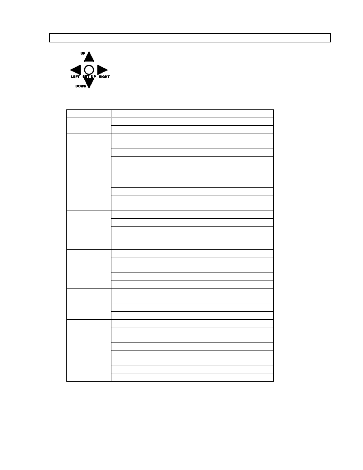
OSD Control
Controls for OSD - On Screen Display
③ Power LED
This LED turns ON only when the power is supplied properly and the
converter (or the regulator) inside the camera works sell.
Backfocus Mode Button
Eliminate the hassle of backfocusing. No more filters or numerous
adjustments.
Procedure:
1. Push and hold the BACKFOCUS MODE button. The lens iris will
open automatically and the Electronic lris will turn on to prevent
a washed out picture.
2. Adjust the lens for proper focus. If the lens focus range is not
sufficient, adjust the focus screw on the side of the camera.
3. Release the BACKFOCUS MODE button, The lens iris will return
to normal and the Electronic lris will turn off. You're finished!
The camera and lens are now backfocused for proper day and
night operation.
RS-485 Connector
This connector allows for external control of the camera (Pelco D).
⑥ Power input connector (push terminal connector)
Recommended Power Supply (12V DC)
Consum
tion 180 ~ 220mA DC
Use only regulated power supply.
Recommended Power Supply (24V AC)
Consumption 100 ~ 150mA AC.
CAUTIONS
1. Connecto to a Class 2 Power Supply only for both of DC 12V
AC 24V.
2. To prevent fire or shock hazard, the UL listed wire VW_I,
style 1007 should be used for the cable for DC 12V or
Page 6

⑦ Camera Mount
g
⑧
⑨
⑩
p
⑪
⑫
For mountin
the camera to standard 1/4-20 mounts
This mount can be mounted on the top or bottom of the camera.
To install this on the top of the camera, remove the "PASSED" label
first and move the mount from the bottom of the camera.
Backfocus Adjustment Screw
This screw is for performing backfocus of the lens and camera.
Adjust if the lens focus is not providing a clear picture.
C-MOUNT ADAPTER RING
When using CS-mount lens (Flange back = 12.5mm), remove
this C-mount adapter ring.
This adapter ring must be in place when using C-mount lenses.
Dust Cam
Remove this cap just before installing the lens.
Do not handle or leave the camera with this cap removed.
Auto iris lens selection switch.
DC for lenses without internal amp. Camera will control the iris.
VIDEO for lenses with internal amp. Lens will control its own iris.
Auto Iris Lens Connector
This connector is for DC drive or Video drive lens.
It supplies the control signals to auto iris lens.
Page 7

⑬ Backfocus Lock Screw
g
a
The position of the CCD can be locked into place after final
adjustment. Please reference the instructions below.
1. Adjust the backfocus of the camera
after installing the lens if you find the
lens focus does not provide enough
range.
2. Ti
hten the lock screw on the camer
to keep the mechanism from moving
due to vibration or movement of the
camera.
Page 8
OSD adjustment
MASK 1
ON/OFF
OSD Direction & Enter button in rear plate
* To access OSD menu, push the SET UP button.
OSD menu description
Sub menu
EXPOSURE
AWB MODE
R-Y GAIN
IMAGE
FUNCTION
EFFECT
PRIVACY ON/OFF selectable
SYSTEM
OPTION
EXIT
B-Y GAIN
SHARPNESS
GAMMA SET
D&N MODE
BURST
COLOR → BW
BW → COLOR
DLY(delay) TIME
MIRROR
WIDE BLC
MASK 2
MASK 3
MASK 4
COLOR SET
FACTORY SET
BLACK BOARD
DPC SET
SYNC MODE
BAUDRATE
PROTOCOL
SAVE/EXIT
RELOAD & EXIT
OSD adjustmentMain menu
LENS
AGC
0.3, 0.35, 0.4, 0.45, 0.5, 0.55, 0.6, 1 selectable
LSC
HLM
BLC
Mask color can be shown with 3 color (Red, Blue,Black)
TITLE
SPLIT
ID
2400/4800/9600/14400/19200/38400 selectable
EXIT Exit the OSD menu
MANUAL/DC selectable
0/18/24/33 selectable
AWC/ATW/MANUAL/PUSH selectable
0 ~ 255 selectable
0 ~ 255 selectable
0 ~ 49 selectable
AUTO/COLOR/B&W/EX-CONT selectable
ON/OFF selectable
0 ~ 255 selectable
0 ~ 213 selectable
3~12 selectable
ON/OFF selectable
ON/OFF selectable
ON/OFF selectable
ON/OFF selectable
ON/OFF selectable
selectable
ON/OFF selectable
ON/OFF selectable
ON/OFF selectable
Load factory defaults
ON/OFF selectable
ON/OFF selectable
ON/OFF selectable
INTERNERAL/AUTO selectable
0 ~ 254 selectable
PELCO D
Save settings and exit
Reload previous settings
Page 9

OSD Menus
Use the OSD adjustment to navigate the menus, press the button for "Enter"
SETUP menu Description
EXPOSURE
EXPOSURE
LENS SEL. DC
LENS SEL. DC
BRIGHT 35
BRIGHT 35
DC LV. 35
DC LV. 35
SHUTTER 1/60
SHUTTER 1/60
AGC 24 DB
AGC 24 DB
1. LENS SEL : This menu is for lens application.
EXPOSURE
Lens Type
DC
Video DC
Manual MANUAL
Shutter speed can also be set manually
* NTSC : AUTO(1/60-1/100,000), 1/60, 1/100FLC, 1/120, 1/250, 1/500, 1/1000, 1/2000, 1/4000, 1/10000, 1/100000
* PAL : AUTO(1/50-1/100,000), 1/50, 1/100, 1/120FLC, 1/250, 1/500, 1/1000, 1/2000, 1/4000, 1/10000, 1/100000
2. BRIGHT : Brightness is adjustable from 0~100.
3. DC LV : DC drive lens level is adjustable from 0 to 100
4. AGC : AGC gain adjustable as a step (0.18,24,33). Higher values will increase sensitivity.
* Note : Higher AGC levels will increase the amount of "noise" in the picture.
Lens Sel.
DC
Shutter
1/60 (1/50 PAL)
1/60 (1/50 PAL)
AUTO
Switch on side of camera setting
DC
Video
N/A
IMAGE
IMAGE
IMAGE
AWB MODE ATW
R GAIN 100
B GAIN 100
R_Y GAIN 128
B_Y GAIN 128
SHARPNESS 20
GAMMA SET 0.45
1. AWB MODE : AWC, ATW, Manual and Push are selectable.
* AWC : Auto white balance works infinitely
Note : when monitoring a single color the camera will attempt to adjust until the picture is white
* ATW : Fixing Auto white balance from 2500k~ 8500k° approximately.
* MANUAL : The range of White balance is adjustable with R GAIN and B GAIN (fixed white balance)
Note : R GAIN & B GAIN is available in Manual mode ( each is adjustable from 0 to 255,)
* PUSH: White balance is fixed to the current color temperature.
Note : if this mode is selected, Auto white balance does not work.
2. R-Y GAIN : Red gain adjustable from 0 to 255.
3. B-Y GAIN : Blue gain adjustable from 0 to 255.
4. SHARPNESS : sharpness is adjustable from 0 to 49
5. GAMMA SET : Gamma characteristic is adjustable with 0.3, 0.35, 0.4, 0.45, 0.5, 0.55, 0.6, 1 .
Page 10
FUNCTION
EFFECT
FUNCTION
FUNCTION
DN MODE COLOR
DN MODE COLOR
BURST OFF
BURST OFF
COLOR▶BW 120
COLOR▶BW 120
BW▶COLOR 80
BW▶COLOR 80
DLY TIME 3
DLY TIME 3
1. DN MODE : Day & Night function is selectable as below.
* AUTO : camera will be color during the day and B&W at night
* COLOR : camera will remain in color at all times
* BW : camera will remain in B&W at all times
2. BURST : Burst ON/ OFF is adjustable (only available in AUTO and EX-CONT mode)
3. COLOR ▶ BW : controls the switching point from Color to B&W for day/night mode
--> Higher numbers will cause the camera to switch to B&W in darker scenes
4. BW ▶ Color : controls the switching point from B&W to Color to for day/night mode
--> Higher numbers will cause the camera to switch to Color in darker scenes
5. DLY TIME : Adjusts the delay time when switching day/night modes
--> Higher numbers will increase the delay
EFFECT
EFFECT
MIRROR
MIRROR
OFF
OFF
LSC
LSC
OFF
OFF
LSC GAIN 8
LSC GAIN 8
HLI
HLI
OFF
OFF
HLI THR 10
HLI THR 10
BLC
BLC
1. MIRROR : Mirror function on/off is selectable.
2. LSC (lens shading compensation) : this function helps prevent darker edges (shading) that can occur with some lenses.
--> Higher values will increase the compensation
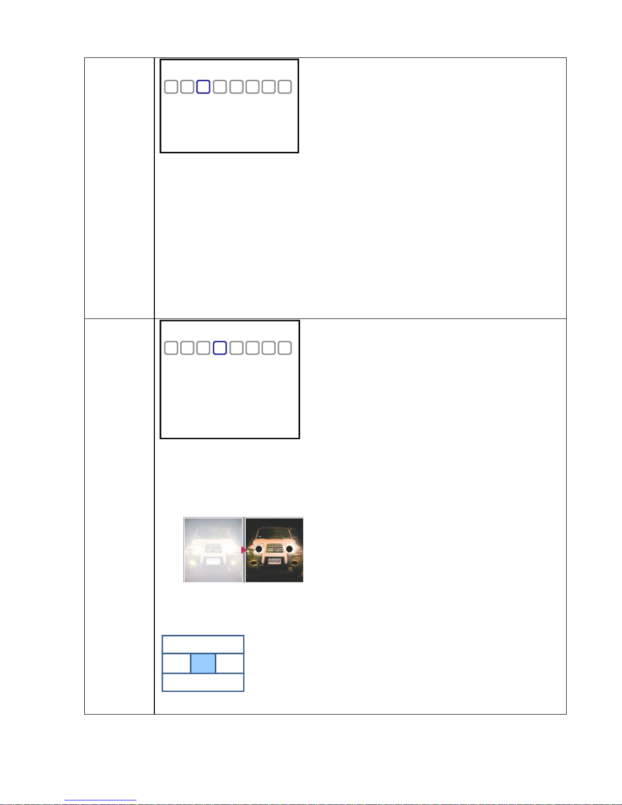
3. HLI (High Light Inversion) :
Helps "mask" bright areas of the scene (like car headlights or bright street lights)
HLI OFF mode HLI ON mode
4. BLC : adjusts the sensitivity of BLC (Backlight Compensation).
WEIGHT allows access to the 5 BLC zones.
0 25500
0
5. WIDE BLC : Digitial WDR (Wide Dynamice Range) to help balance out high contrast scenes and prevent washout..
Each BLC zone has number showing BLC sensitivity adustable from 0 to 255.
A higher number increases the BLC sensitivity.
* Note : only the center zone is set to 255 by default
Page 11

PRIVACY
PRIVACY
PRIVACY
MASK1 OFF
MASK1 OFF
SET AREA↓
SET AREA↓
MASK2 OFF
MASK2 OFF
SET AREA↓
SET AREA↓
MASK3 OFF
MASK3 OFF
SET AREA↓
SET AREA↓
MASK4 OFF
MASK4 OFF
SET AREA↓
SET AREA↓
COLOR BLACK
COLOR BLACK
This mode allows for up for Privacy Zones (masks) to cover areas that are not be viewed or recorded
Up to for zones can be selected (Mask 1, 2, 3, 4)
After turning the mask on, select SET AREA to create the mask
To create a mask area (press Enter to switch between the colors below):
* When the mask is Red it can be adjusted in size Up and Left
* When the mask is Blue it can be adjusted in size Down and Right
* When the mask is Black you can return to the menu by moving in any direction
You can select the COLOR of the masks at the bottom of the menu
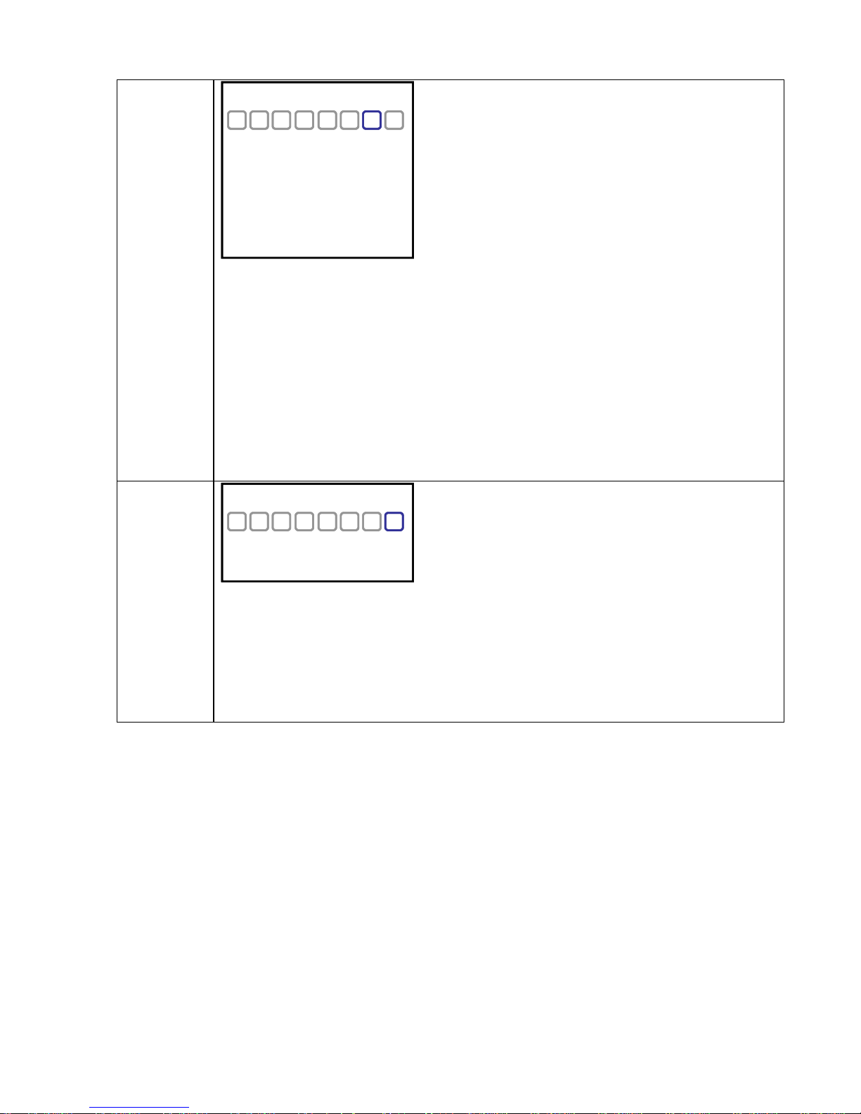
SYSTEM
SYSTEM
TITLE ON
TITLE ON
EDIT↓
EDIT↓
POSITION TOP_L
POSITION TOP_L
FACTORY SET↓
FACTORY SET↓
BACKBOARD ON
BACKBOARD ON
SPLIT OFF
SPLIT OFF
SYSTEM
1. TITLE : Turning this mode ON will allow the camera to display and ID number or title
- EDIT : after pushing the SET UP button, each character appears with the vertical order as shown below.
* To erase a character, choose the empty mark among the characters
SYSTEM
O
P
Q
R
[C A M ]
S
T
SYSTEM
This is delete (empty )mark
]
for erasing a wrong entry
▲
↓
[C A M ]
■
U
<TITLE wording>
* Note : move the cursor all the way right after finishing before hitting enter (SET UP button).
- POSITION : the location of the title can be adjusted here
2. FACTORY SET : If push SET, all camera values retun to the factory default values.
3. BACKBOARD : OSD backboard (background) can be turned ON or OFF.
4. SPLIT : it splits the monitoring picture into two pictures.
<Erasing word>
Page 12
SPECIAL
EXIT
SPECIAL
DPC SET OFF
DPC SET OFF
WHITE TH 30
WHITE TH 30
BLACK TH 50
BLACK TH 50
LUM TH 150
LUM TH 150
SYNC MODE INTER
SYNC MODE INTER
V_PHASE 0
V_PHASE 0
ID 1
ID 1
BAUDRATE 2400
BAUDRATE 2400
PROTOCOL PELCO_D
PROTOCOL PELCO_D
OPTION
1. DPC (Defective Pixel Cancelling) SET : compensates for white and black defects on the CCD
- WHITE TH : a white defect is compensated with an adjustment value from 0 To 255
- BLACK TH : a black defect is compensated with an adjustment value from 0 to 255
- LUM TH : a luminance is compensated with an adjustment value from 0 To 255
2. SYNC MODE : camera sync. is selectable.
INTER : for Internal sync. AUTO : for Line-lock
* V-PHASE is available only in AUTO mode (from 0 to 199)
3. ID : selects the camera ID for RS485 communication with external devices.
ID number can be set from 0 to 254
4. BAUDRATE : adjust the baud rate to match the RS485 communcation speed of the external device
6. PROTOCOL : PELCO-D
EXIT
EXIT
SAVE/EXIT↓
SAVE/EXIT↓
RELOAD/EXIT↓
RELOAD/EXIT↓
EXIT↓
EXIT↓
1. SAVE / EXIT :
Select to SAVE all changes made
2. RELOAD/EXIT
Select to RELOAD the previous settings saved before entering the menus
Note : this is not recover the factory default values.
3. EXIT :
If user do not want to save the new adjusted values, select this item
Page 13
SPECIFICATIONS FOR CLD54D
Video Signal System
Image Sensor
Image Output
Scanning System
Resolution (horizontal)
Sensitivity (F1.2)
S/N Ratio
Gamma Characteristics
Effective Picture Elements
Synchronization System
Auto lris Control
Auto Electronic Shutter (AES)
Automatic Gain Control (AGC)
Back Light Compensation (BLC)
White Balance
Digital WDR
High Light Inversion
Privacy Masking
Video Control
Day & Night Function
OSD
Lens Mount
Power Supply (dual power)
Power Consumption
Ambient temp.(operation)
Ambient Humid.(operation)
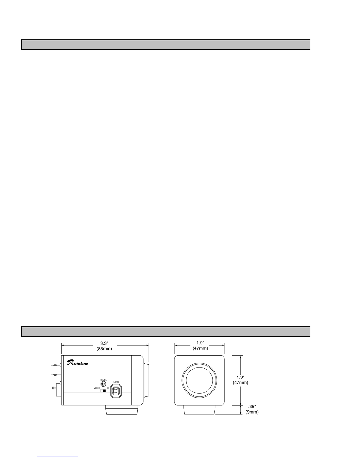
External Dimensions
Weight
Terminal (Rear side)
Back Focus Adjustment
NTSC (CLD54D) / PAL (CLD54DX)
Interline 1/3" Sony Super HAD-Ⅱ CCD
VBS compoite 1.0Vp-p/75 ohms
2:1 Interlace
540 TV lines or more at center
0.1 Lux
48dB or more (AGC-OFF)
0.45
768(H) x 494(V) (NTSC), 752(H) x 582(V) (PAL)
Internal / Linelock (OSD)
Video iris / DC iris (Switchable)
1/60 ~ 1/100,000 linear (NTSC), 1/50 ~ 1/100,000 (PAL)
On / Off Selectable (Adjustable levels of 0, 18, 24, 32dB)
On / Off Selectable (5 Area Masking)
AWC / ATW / Manual
Off / WDR / BLC Selectable
On / Off Selectable
On / Off (4 Programmable Zone)
Reverse, Posi / Nega, Sharpness
Color / BW / Auto (camera is not IR sensitive)
Camera ID & Functions Selectable
CS-mount (C-mount adapter included)
12VDC/24VAC ±10% (Isolated Power Supply Built Into Camera)
5W or less
+14 ~ 122°F (-10°C ~ +50°C) Within 85% RH
85%RH or less
1.9 × 1.9 × 3.3 inches (47 × 47 × 83mm)
7.1 oz. (200g)
Video Output : BNC
Power Input : 2-Pin Push Terminal
DC/VIDEO Auto Iris Lens Select Switch
A.I Lens, DC Drive Lens : 4-Pin Square DIN (Switch)
One Touch Screw Driving System
DIMENSIONS
Page 14

SPECIFICATIONS FOR DNL54D
Video Signal System
Image Sensor
Image Output
Scanning System
Resolution (horizontal)
Sensitivity (F1.2)
S/N Ratio
Gamma Characteristics
Effective Picture Elements
Synchronization System
Auto lris Control
Auto Electronic Shutter (AES)
Automatic Gain Control (AGC)
Back Light Compensation (BLC)
White Balance
Digital WDR
High Light Inversion
Privacy Masking
Video Control
Day & Night Function
OSD
Lens Mount
Power Supply (dual power)
Power Consumption
Ambient temp.(operation)
Ambient Humid.(operation)
External Dimensions
Weight
Terminal (Rear side)
Back Focus Adjustment
NTSC (DNL54D) / PAL (DNL54DX)
Interline 1/3" Sony Super HAD-Ⅱ CCD
VBS compoite 1.0Vp-p/75 ohms
2:1 Interlace
540 TV lines or more at center
0.03 Lux
48dB or more (AGC-OFF)
0.45
768(H) x 494(V) (NTSC), 752(H) x 582(V) (PAL)
Internal / Linelock (OSD)
Video iris / DC iris (Switchable)
1/60 ~ 1/100,000 linear (NTSC), 1/50 ~ 1/100,000 (PAL)
On / Off Selectable (Adjustable levels of 0, 18, 24, 32dB)
On / Off Selectable (5 Area Masking)
AWC / ATW / Manual
Off / WDR / BLC Selectable
On / Off Selectable
On / Off (4 Programmable Zone)
Reverse, Posi / Nega, Sharpness
Color / BW / Auto
Camera ID & Functions Selectable
CS-mount (C-mount adapter included)
12VDC/24VAC ±10% (Isolated Power Supply Built Into Camera)
5W or less
+14 ~ 122°F (-10°C ~ +50°C) Within 85% RH
85%RH or less
1.9 × 1.9 × 3.3 inches (47 × 47 × 83mm)
7.1 oz. (200g)
Video Output : BNC
Power Input : 2-Pin Push Terminal
DC/VIDEO Auto Iris Lens Select Switch
A.I Lens, DC Drive Lens : 4-Pin Square DIN (Switch)
One Touch Screw Driving System
DIMENSIONS
 Loading...