

Page 1
General Description
The MAX9890 provides click-and-pop suppression for
devices such as CODECs with integrated headphone
amplifiers that lack a clickless/popless startup/powerup or shutdown/power-down. The device controls the
ramping of the DC bias voltage on the output-coupling
capacitors and the application of the audio signal to
ensure that no audible transients are present at the
headphones. The MAX9890A features a 200ms startup
time for use with up to 100µF coupling capacitors. The
MAX9890B features a 330ms startup time for use with
greater than 100µF coupling capacitors.
The MAX9890 consumes 14µA of supply current and
0.001µA in shutdown, while contributing less than
0.003% THD+N into a 32Ω load. ESD (Human Body
Model) protection circuitry on the outputs protect the
MAX9890 and devices further up the signal chain from
ESD strikes up to ±8kV.
The MAX9890 is available in a miniature (1.5mm ✕
1.5mm ✕ 0.6mm) 9-bump chip-scale package (UCSP™),
as well as an 8-pin TDFN package (3mm ✕ 3mm ✕
0.8mm), and is specified for operation over the
-40°C to +85°C extended temperature range.
Applications
High-End Notebook Audio PDAs
Portable DVD Players Cell Phones
Portable MP3 Players
Features
♦ 36dB Click-Pop Suppression
♦ 2.7V to 5.5V Single-Supply Operation
♦ Clickless/Popless Startup/Power-Up and
Shutdown/Power-Down
♦ 0.001µA Low-Power Shutdown Mode
♦ THD+N < 0.003% Into 32Ω
♦ ±8kV ESD Protection (Human Body Model)
♦ Requires Only One 0.1µF Capacitor to Complete
the Circuit
♦ Low 14µA Supply Current
♦ Tiny Packaging
9-Bump UCSP (1.5mm x 1.5mm x 0.6mm)
8-Pin TDFN (3mm x 3mm x 0.8mm)
MAX9890
Audio Click-Pop Suppressor
________________________________________________________________ Maxim Integrated Products 1
Ordering Information
19-2932; Rev 0; 8/03
For pricing, delivery, and ordering information, please contact Maxim/Dallas Direct! at
1-888-629-4642, or visit Maxim’s website at www.maxim-ic.com.
Selector Guide
UCSP is a trademark of Maxim Integrated Products, Inc.
*Future product—contact factory for availability.
**EP = Exposed pad.
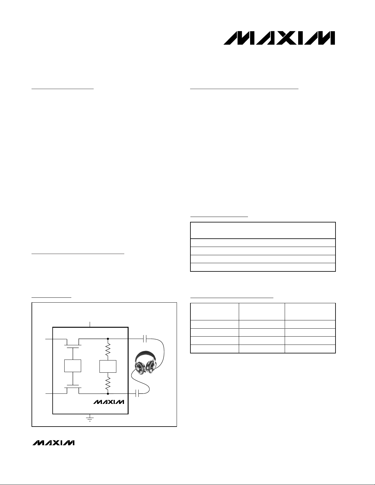
Simplified Block Diagram
Typical Application Circuit and Pin Configurations appear
at end of data sheet.
PART TEMP RANGE
M AX 9890AE BL- T* -40°C to +85°C 9 UCSP-9 ADV
MAX9890AETA -40°C to +85°C 8 TDFN-EP** AHA
M AX 9890BE BL- T* -40°C to +85°C 9 UCSP-9 ADW
MAX9890BETA -40°C to +85°C 8 TDFN-EP** AHB
PINPACKAGE
TOP
MARK
SINGLE SUPPLY
2.7V TO 5.5V
RAMP
DOWN
MAX9890
OUTL
OUTR
INL
RAMP
UP
INR
PART PIN-PACKAGE
MAX9890AEBL-T 9 UCSP-9 200
MAX9890AETA 8 TDFN-EP 200
MAX9890BEBL-T 9 UCSP-9 330
MAX9890BETA 8 TDFN-EP 330
SWITCH TURN-ON
TIME (ms)
Page 2
MAX9890
Audio Click-Pop Suppressor
2 _______________________________________________________________________________________
ABSOLUTE MAXIMUM RATINGS
Stresses beyond those listed under “Absolute Maximum Ratings” may cause permanent damage to the device. These are stress ratings only, and functional
operation of the device at these or any other conditions beyond those indicated in the operational sections of the specifications is not implied. Exposure to
absolute maximum rating conditions for extended periods may affect device reliability.
(All Voltages are Referenced to GND)
V
CC
........................................................................................+6V
CEXT, SHDN, OUT_ .................................................-0.3V to +6V
IN_ ..............................................................-0.3V to (V
CC
+ 0.3V)
Continuous Current (IN_, OUT_).....................................±150mA
Continuous Current (All Other Pins) .................................±20mA
Continuous Power Dissipation (T
A
= +70°C)
8-Pin TDFN (derate 24.4mW/°C above +70°C) ..........1951mW
9-Bump UCSP (derate 4.7mW/°C above +70°C)..........379mW
Operating Temperature Range ...........................-40°C to +85°C
Storage Temperature Range .............................-65°C to +150°C
Junction Temperature......................................................+150°C
Lead Temperature (soldering, 10s) .................................+300°C
Bump Temperature (soldering)
Reflow ...........................................................................+235°C
ELECTRICAL CHARACTERISTICS
(VCC= 3V, SHDN = VCC, GND = 0, C
CEXT
= 0.1µF, TA= T
MIN
to T
MAX
, unless otherwise noted. Typical values are at TA= +25°C.)
(Note 1)
PARAMETER
SYMBOL
CONDITIONS
MIN
TYP
MAX
UNITS
Supply Voltage Range V
CC
Inferred from RON test 2.7 5.5 V
Supply Current I
CC
(Note 2) 14 22 µA
Shutdown Supply Current I
SHDN
SHDN = GND
1µA
Input Voltage Range Inferred from RON test 0
V
VCC = 5.5V 0.4 1
On-Resistance R
ON
Over input voltage
range
V
CC
= 2.7V 0.7 1.5
Ω
On-Resistance Flatness
)
Over input voltage range 2 mΩ
Output Discharge Resistance
)
kΩ
Input Off-Leakage Current SHDN = GND
1µA
VCC Power-Down Threshold
(Note 3)
V
UVLO
VCC falling 2.5 V
Click-Pop Reduction 36 dB
ESD Protection OUT_, Human Body Model ±8kV
DYNAMIC
MAX9890A
Turn-On Time (Note 4) t
ON
MAX9890B
ms
Turn-Off Time t
OFF
(Note 5)
ns
Bandwidth
kHz
Total Harmonic Distortion Plus
Noise
RL = 32Ω, 30mW, f = 1kHz
%
Off-Isolation, IN_ to OUT_ f = 20kHz, SHDN = GND, RL = 32Ω
dB
Crosstalk (Switches ON) f = 20kHz
dB
V
RIPPLE
= 0.5V
P-P
at 20Hz, fIN = 3kHz at
1V
P-P
, RL = 32Ω
V
RIPPLE
= 0.5V
P-P
at 1kHz, fIN = 3kHz at
1V
P-P
, RL = 32Ω
Power-Supply Rejection Ratio
(Note 6)
PSRR
V
RIPPLE
= 0.5V
P-P
at 20kHz, fIN = 3kHz
at 1V
P-P
, RL = 32Ω
-84
dB
0.001
V
CC
R
FLAT(ON
R
OUT(DIS
THD+N
220
0.001
200
330
120
>100
0.003
-108
-100
-100
-100
Page 3
MAX9890
Audio Click-Pop Suppressor
_______________________________________________________________________________________ 3
ELECTRICAL CHARACTERISTICS (continued)
(VCC= 3V, SHDN = VCC, GND = 0, C
CEXT
= 0.1µF, TA= T
MIN
to T
MAX
, unless otherwise noted. Typical values are at TA= +25°C.)
(Note 1)
Note 1: All devices are 100% tested at TA= +25°C. All temperature limits are guaranteed by design.
Note 2: Supply current is measured when switch is on (i.e., SHDN = V
CC
, t > tON).
Note 3: Supply voltage level where the device enters its power-down cycle.
Note 4: Turn-on time is measured from the time V
CC
= 3V and SHDN > VIHuntil the RONspecification is met.
Note 5: Switch turn-off time is measured from the time SHDN < V
IL
or VCC< V
UVLO
until the off-isolation specification is met.
Note 6: See the Power-Supply Rejection Ratio section for test method.
Typical Operating Characteristics
(VCC= 3V, C
CEXT
= 0.1µF, typical values are at TA= +25°C, unless otherwise noted.)
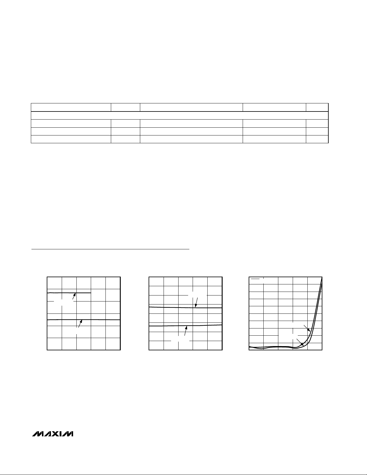
ON-RESISTANCE vs. IN_ VOLTAGE
MAX9890 toc01
IN_ VOLTAGE (V)
ON-RESISTANCE (Ω)
4321
0.3
0.4
0.5
0.6
0.7
0.8
0.2
05
VCC = 3V
VCC = 5V
SUPPLY CURRENT vs. TEMPERATURE
MAX9890 toc02
TEMPERATURE (°C)
SUPPLY CURRENT (µA)
6035-15 10
5
10
15
20
25
30
35
40
0
-40 85
VCC = 5.5V
VCC = 2.7V
SHUTDOWN CURRENT vs. TEMPERATURE
MAX9890 toc03
TEMPERATURE (°C)
SHUTDOWN CURRENT (pA)
603510-15
100
200
300
400
500
600
700
800
900
1000
0
-40 85
VCC = 2.7V
VCC = 5.5V
SHDN = 0V
PARAMETER SYMBOL CONDITIONS MIN TYP MAX UNITS
LOGIC INPUT (SHDN)
Logic-Input High Voltage V
Logic-Input Low Voltage V
Logic-Input Current I
IH
IL
IN
VCC = 2.7V to 5.5V 2.0 V
VCC = 2.7V to 5.5V 0.8 V
±1 µA
Page 4
MAX9890
Audio Click-Pop Suppressor
4 _______________________________________________________________________________________
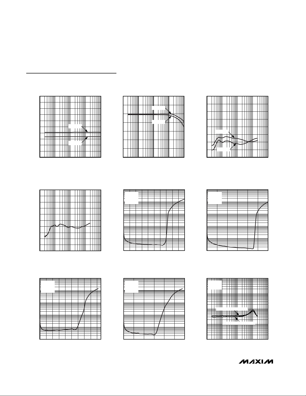
Typical Operating Characteristics (continued)
(VCC= 3V, C
CEXT
= 0.1µF, typical values are at TA= +25°C, unless otherwise noted.)
1.0
0.8
0.6
0.4
0.2
0
-0.2
ON-LOSS (dB)
-0.4
-0.6
-0.8
-1.0
ON-LOSS vs. FREQUENCY
RL = 32Ω
RL = 16Ω
10k1k10010 100k
FREQUENCY (Hz)
MAX9890 toc04
PHASE SHIFT (DEGREES)
PHASE SHIFT vs. FREQUENCY
2
1
0
-1
-2
-3
-4
-5
10010
FREQUENCY (Hz)
RL = 32Ω
RL = 16Ω
10k1k 100k
MAX9890 toc05
OFF-ISOLATION (dB)
OFF-ISOLATION vs. FREQUENCY
10
-10
-30
-50
-70
-90
-110
-130
-150
RL = 32Ω
RL = 16Ω
FREQUENCY (Hz)
MAX9890 toc06
10k1k10010 100k
-50
-60
-70
-80
-90
-100
-110
CROSSTALK (dB)
-120
-130
-140
-150
TOTAL HARMONIC DISTORTION
PLUS NOISE vs. OUTPUT POWER
100
VCC = 3V
= 16Ω
R
L
10
f = 1kHz
1
THD+N (%)
0.1
0.01
CROSSTALK vs. FREQUENCY
10k1k10010 100k
FREQUENCY (Hz)
MAX9890 toc07
MAX9890 toc10
TOTAL HARMONIC DISTORTION
PLUS NOISE vs. OUTPUT POWER
100
VCC = 5V
= 16Ω
R
L
10
f = 1kHz
1
THD+N (%)
0.1
0.01
0.001
0250
OUTPUT POWER (mW)
MAX9890 toc08
THD+N (%)
225200175150125100755025
0.001
TOTAL HARMONIC DISTORTION
PLUS NOISE vs. OUTPUT POWER
100
VCC = 3V
= 32Ω
R
10
1
THD+N (%)
0.1
0.01
L
f = 1kHz
MAX9890 toc11
THD+N (%)
0.001
TOTAL HARMONIC DISTORTION
PLUS NOISE vs. OUTPUT POWER
100
VCC = 5V
= 32Ω
R
L
10
f = 1kHz
1
0.1
0.01
TOTAL HARMONIC DISTORTION
PLUS NOISE vs. FREQUENCY
1
VCC = 5V
= 16Ω
R
L
0.1
0.01
OUTPUT POWER = 25mW
MAX9890 toc09
100806040200120
OUTPUT POWER (mW)
MAX9890 toc12
OUTPUT POWER = 150mW
0.001
0
OUTPUT POWER (mW)
225200175150125100755025
0.001
OUTPUT POWER (mW)
100806040200120
0.0001
10 100k
FREQUENCY (Hz)
10k1k100
Page 5

MAX9890
Audio Click-Pop Suppressor
_______________________________________________________________________________________ 5
Typical Operating Characteristics (continued)
(VCC= 3V, C
CEXT
= 0.1µF, typical values are at TA= +25°C, unless otherwise noted.)
TOTAL HARMONIC DISTORTION
PLUS NOISE vs. FREQUENCY
1
VCC = 5V
= 32Ω
R
L
0.1
0.01
THD+N (%)
0.001
0.0001
OUTPUT POWER = 20mW
OUTPUT POWER = 80mW
10 100k
FREQUENCY (Hz)
STARTUP WAVEFORM (DC)
TOTAL HARMONIC DISTORTION
PLUS NOISE vs. FREQUENCY
1
VCC = 3V
= 16Ω
R
MAX9890 toc13
10k1k100
0.0001
MAX9890 toc16
L
0.1
0.01
THD+N (%)
0.001
10 100k
SHDN
2V/div
V
OUT
1V/div
OUTPUT POWER = 100mW
OUTPUT POWER = 25mW
FREQUENCY (Hz)
MAX9890 toc14
10k1k100
0.0001
SHUTDOWN WAVEFORM (DC)
THD+N (%)
0.001
TOTAL HARMONIC DISTORTION
PLUS NOISE vs. FREQUENCY
1
VCC = 3V
= 32Ω
R
L
0.1
0.01
OUTPUT POWER = 60mW
OUTPUT POWER = 20mW
SHDN
2V/div
10k1k100
10 100k
FREQUENCY (Hz)
MAX9890 toc17
MAX9890 toc15
V
OUT
MAX9890 toc19
1V/div
V
HEADPHONE
10mV/div
SHDN
2V/div
V
OUT
1V/div
V
HEADPHONE
1V/div
40ms/div
STARTUP WAVEFORM (AC)
40ms/div
MAX9890 toc18
V
HEADPHONE
10mV/div
SHDN
2V/div
V
OUT
1V/div
V
HEADPHONE
1V/div
10s/div
SHUTDOWN WAVEFORM (AC)
1s/div
Page 6

MAX9890
Detailed Description
The MAX9890 provides click-and-pop suppression for
single-supply devices such as CODECs and other
headphone amplifiers that do not have click-and-pop
suppression. Single-supply audio amplifier outputs
have a DC bias voltage, V
CC
/ 2, and require large output-coupling capacitors to block the DC voltage from
the speaker. During startup or shutdown, the DC bias
voltage is quickly raised or lowered (Figure 1), resulting
in an audible transient through the headphone load.
The MAX9890 prevents the audible transient by slowly
ramping the DC bias in an S-shaped waveform (Figure
2), suppressing the large transient at the output of the
coupling capacitor. The S-shaped waveform shapes
the frequency spectrum, minimizing the amount of
audible components present at the output.
Internal switches couple the inputs to the outputs after
the coupling capacitors have fully charged to the input
common-mode bias voltage. When power is removed or
the device is put into shutdown, the internal switches in
the MAX9890 immediately disconnect the output and
slowly discharge the coupling capacitors through
220kΩ resistors.
The MAX9890 has an undervoltage lockout (UVLO) that
prevents device operation when VCCis below the
power-down threshold (2.5V, typ). The MAX9890 features ±8kV ESD (Human Body Model) protection on the
audio outputs.
Startup
The MAX9890 monitors VCCand SHDN. The UVLO
holds the device off when VCCis below the powerdown threshold (V
UVLO
) or SHDN is held low. The
device needs both VCCabove the power-down thresh-
old and SHDN = high for the part to start up. Once the
supply voltage is above the power-down threshold and
SHDN is high, the device charges the coupling capacitors to the input DC bias voltage using CEXT to control
the ramp. After the DC bias ramp, the internal switches
close, coupling the audio input to the output. The
MAX9890 provides click-pop suppression even if the
output blocking capacitors are already partially or fully
charged.
The MAX9890A features a 200ms switch turn-on time,
enabling the use of up to 100µF coupling capacitors at
the output for applications requiring only a limited lowfrequency response and a rapid turn-on time. The
MAX9890B features a 330ms switch turn-on time,
enabling the use of >100µF coupling capacitors at the
output for extended low-frequency response applications. For optional click-pop suppression, mute the
audio signal until after the turn-on time has elapsed.
The internal switches stay closed as long as V
CC
is
above the power-down threshold voltage and SHDN is
high. Figures 1 and 2 show typical startup/power-up
sequences with and without click-pop suppression.
Shutdown
If the supply voltage falls below the UVLO threshold or
if SHDN is driven low, the device enters low-power
shutdown mode. In low-power shutdown mode, quiescent current reduces to 0.001µA. The switches are
immediately turned off and 220kΩ resistors slowly
bleed the charge off the coupling capacitors. Figures 3
and 4 show typical shutdown/power-down sequences
with and without click-pop suppression. For optiomal
click-pop performance, mute the audio signal before
shutting down the MAX9890.
Audio Click-Pop Suppressor
6 _______________________________________________________________________________________
Pin Description
PIN/BUMP
TDFN UCSP
1A2VCCPower Supply. VCC accepts 2.7V to 5.5V input supply. Bypass VCC to GND with a 1µF capacitor.
2A3SHDN
3 B3 INL Left-Channel Audio Input. Connect to output of headphone amplifier.
4 C3 OUTL Left-Channel Audio Output. AC couple to headphone.
5 C2 GND Ground
6 C1 OUTR Right-Channel Audio Output. AC couple to headphone.
7 B1 INR Right-Channel Audio Input. Connect to output of headphone amplifier.
8 A1 CEXT External Capacitor. Connect a 0.1µF capacitor from CEXT to GND.
NAME FUNCTION
Active-Low Shutdown. Connect SHDN to GND to enter a 0.1µA shutdown mode. Connect SHDN
to V
for normal operation.
CC
Page 7

Switches
The MAX9890’s internal switches connect the input to the
output after the coupling capacitors are fully charged.
The MAX9890A holds the switches open for 200ms and is
ideal for coupling capacitors less than 100µF. The
MAX9890B has a longer turn-on time of 330ms and is
ideal with larger coupling capacitors less than 220µF. The
internal switches have a low on-resistance (RON= 0.5Ω)
and on-resistance flatness (R
FLAT(ON)
= 2mΩ) minimizing
total harmonic distortion plus noise (THD+N). The relationship below shows the contribution to THD+N through
the switch, due to on-resistance and on-resistance flat-
MAX9890
Audio Click-Pop Suppressor
_______________________________________________________________________________________ 7
0dB
Figure 1. Startup/Power-Up Sequence Without Click-Pop
Suppression
Figure 2. Startup/Power-Up Sequence With Click-Pop
Suppression
Figure 3. Shutdown/Power-Down Sequence Without Click-Pop
Suppression
Figure 4. Shutdown/Power-Down Sequence With Click-Pop
Suppression
V
CC
2V/div
V
OUT
1V/div
/SHDN
0dB
V
2V/div
V
1V/div
CC
OUT
/SHDN
V
HEADPHONE
100mV/div
FFT
HEADPHONE
20dB/div
40ms/div
FFT: 25Hz/div
VCC/SHDN
2V/div
0dB
100ms/div
FFT: 25Hz/div
V
OUT
1V/div
V
HEADPHONE
500mV/div
FFT
HEADPHONE
20dB/div
V
HEADPHONE
50mV/div
FFT
HEADPHONE
20dB/div
40ms/div
FFT: 25Hz/div
/SHDN
V
CC
2V/div
0dB
100ms/div
FFT: 25Hz/div
V
OUT
1V/div
V
HEADPHONE
20mV/div
FFT
HEADPHONE
20dB/div
Page 8

MAX9890
ness (on-resistance flatness is defined as the difference
between the maximum and minimum values of on-resistance measured over the specific analog-signal range).
Power-Supply Rejection Ratio (PSRR)
PSRR is the measurement of AC power-supply ripple or
noise that couples to the output. Variations in supply voltage corrupt the audio signal, due to changes in the R
ON
value by supply modulation. The FFT shown in Figure 5
was taken with a 19kHz 1V
P-P
sine wave onto the 5V DC
supply voltage, and a 20kHz 1V
P-P
sine wave applied at
IN_ with a 32Ω load is shown in Figure 6. The MAX9890
maintains a -100dB (typ) PSRR across the supply voltage
range eliminating any corruption of the audio signal from
supply variations. Therefore, with a zero audio signal, the
RONvariation due to supply voltage ripple does not contribute to any output signal modulation.
Low-Frequency Response
In addition to the cost and size disadvantages of the
output-coupling capacitors, these capacitors limit the
amplifier’s low-frequency response and can distort the
audio signal.
The impedance of a headphone or speaker load and
the output-coupling capacitor form a highpass filter with
the -3dB point set by:
where RLis the headphone impedance and C
OUT
is
the output-coupling capacitor value. The highpass filter
is required by conventional single-ended, single powersupply headphone drivers to block the midrail DC bias
component of the audio signal from the headphones.
The drawback to the filter is that it can attenuate lowfrequency signals. Larger values of C
OUT
reduce this
effect but result in physically larger, more expensive
capacitors. Figure 7 shows the relationship between the
size of C
OUT
and the resulting low-frequency attenuation. Note that the -3dB point for a 16Ω headphone with
a 100µF blocking capacitor is 100Hz, well within the
normal audio band, resulting in low-frequency attenuation of the reproduced signal.
The MAX9890A and MAX9890B have different turn-on
times to accommodate different size output-coupling
capacitors (see Table 1). Using a capacitor smaller
than the specified maximum allowed does not degrade
click-pop suppression. Therefore, capacitors less than
100µF can be used with the A or B version devices.
f
RC
dB
L OUT
−=3
1
2π
THD
R
R
MAXIMUM
FLAT ON
LOAD
=×
()
%
4
100
Audio Click-Pop Suppressor
8 _______________________________________________________________________________________
Figure 5. FFT for PSRR
Figure 6. PSRR Test Circuit
VCC = 4.5V TO 5.5V, f
R
10
0
-10
-20
-30
-40
-50
-60
-70
-80
-90
-100
OUTPUT SPECTRUM (dBV)
-110
-120
-130
-140
15 17 19 21 23 25
= 32Ω, VIN = 1V
L
FREQUENCY (kHz)
= 19kHz,
VCC
, fIN = 20kHz
P-P
VDC = 5V
V
= 1V
AC
19kHz
V
DC
V
AC
20kHz
= 2.0V
= 1V
P-P
IN_
P-P
RAMP
IN_
V
CC
UP
RAMP
DOWN
SHDN
OUT_
OUT_
R
L
MAX9890
Page 9

External Capacitor (C
CEXT
)
The external click-pop suppression capacitor at CEXT
serves a dual purpose. On power-up, C
CEXT
is
charged by an internal current source and is used to
slowly ramp up the external coupling capacitors. When
the device is powered down, C
CEXT
powers the internal
circuitry used to drain the external coupling capacitors.
A 0.1µF capacitor between CEXT and GND provides
clickless/popless operation with coupling capacitors for
both the MAX9890A and MAX9890B, even with the
rapid removal of supply voltage.
Applications Information
Layout
Good layout improves performance by decreasing the
amount of stray capacitance and noise. To decrease
stray capacitance, minimize PC board trace lengths
and resistor leads, and place external components as
close to the device as possible.
Power Supply and Bypassing
The excellent PSRR of the MAX9890 allows it to operate
from noisy power supplies. In most applications, a
0.1µF capacitor from VCCto GND is sufficient. This
bypass capacitor should be placed close to VCC.
UCSP Applications Information
For the latest application details on UCSP construction,
dimensions, tape-carrier information, printed circuit
board techniques, bump-pad layout, and recommended reflow temperature profile, as well as the latest information on reliability testing results, refer to the
Application Note, “UCSP—A Wafer-Level Chip-Scale
Package” available on Maxim’s website at www.maximic.com/ucsp.
Chip Information
TRANSISTOR COUNT: 1001
PROCESS: BiCMOS
MAX9890
Audio Click-Pop Suppressor
_______________________________________________________________________________________ 9
Figure 7. Low-Frequency Attenuation for Common DC-Blocking
Capacitor Values
Table 1. Coupling Capacitor
*May experience some degradation of click-pop suppression.
LOW-FREQUENCY ROLLOFF
0
-3
-6
-9
-12
-15
-18
ATTENUATION (dB)
-21
-24
-27
-30
10 100 1k 10k 100k
= 16Ω)
(R
L
330µF
220µF
100µF
33µF
FREQUENCY (Hz)
CAPACITOR
SIZE (µF)
33 √√
47 √√
100 √√
150 * √
220 * √
330 — *
470 — *
MAX9890A
TURN-ON TIME
(200ms)
MAX9890B
TURN-ON TIME
(300ms)
Page 10

MAX9890
Audio Click-Pop Suppressor
10 ______________________________________________________________________________________
Pin Configurations
HPLOUT
HPROUT
STARTUP AND
SHUTDOWN
CONTROL
GND
SHDN
OUTL
OUTR
INL
INR
CEXT
V
CC
0.1µF
1µF
5
7
3
2
4
6
8
1
2.7V TO 5.5V
( ) UCSP BUMP.
*USER-DEFINED VALUE.
(A2)
(A1)
(C3)
(C1)
(C2)
(B1)
(B3)
(A3)
*
*
MAX9890
RAMP-UP AND
RAMP-DOWN
CONTROL
CODEC
WITH INTEGRATED
HEADPHONE
DRIVERS
Typical Application Circuit
TOP VIEW
MAX9890
V
SHDN
INL
OUTL
1
CC
2
3
4
8
CEXT
7
INR
OUTR
6
GND
5
(BUMPS ON BOTTOM)
12 3
A
B
CEXT
INR
V
CC
MAX9890
SHDN
INL
TDFN-EP
NOTE:
GND IS CONNECTED TO THE UNDERSIDE METAL SLUG.
C
OUTR
GND
OUTL
UCSP
Page 11

MAX9890
Audio Click-Pop Suppressor
______________________________________________________________________________________ 11
Package Information
(The package drawing(s) in this data sheet may not reflect the most current specifications. For the latest package outline information,
go to www.maxim-ic.com/packages
.)
Page 12

MAX9890
Audio Click-Pop Suppressor
Maxim cannot assume responsibility for use of any circuitry other than circuitry entirely embodied in a Maxim product. No circuit patent licenses are
implied. Maxim reserves the right to change the circuitry and specifications without notice at any time.
12 ____________________Maxim Integrated Products, 120 San Gabriel Drive, Sunnyvale, CA 94086 408-737-7600
© 2003 Maxim Integrated Products Printed USA is a registered trademark of Maxim Integrated Products.
Package Information (continued)
(The package drawing(s) in this data sheet may not reflect the most current specifications. For the latest package outline information,
go to www.maxim-ic.com/packages
.)
PIN 1
INDEX
AREA
D
COMMON DIMENSIONS
MIN. MAX.
SYMBOL
0.70 0.80
A
2.90 3.10
D
2.90 3.10
E
0.00 0.05
A1
L
0.20 0.40
k
0.25 MIN.
A2 0.20 REF.
A
A2
E
DETAIL A
A1
L
A
NUMBER OF LEADS SHOWN ARE FOR REFERENCE ONLY
D2
b
E2
C
L
e
C0.35
e
e
DALLAS
SEMICONDUCTOR
PROPRIETARY INFORMATION
TITLE:
PACKAGE OUTLINE, 6, 8 & 10L,
TDFN, EXPOSED PAD, 3x3x0.80 mm
APPROVAL
C
L
DOCUMENT CONTROL NO. REV.
L
PIN 1 ID
1N1
[(N/2)-1] x e
REF.
k
L
21-0137 D
6, 8, &10L, QFN THIN.EPS
1
2
PACKAGE VARIATIONS
PKG. CODE
T633-1 1.50–0.10D22.30–0.10
N
6
1.50–0.10
E2
2.30–0.10T833-1 8
JEDEC SPEC
0.95 BSCeMO229 / WEEA
MO229 / WEEC
0.65 BSC
[(N/2)-1] x e
0.40–0.05b1.90 REF
1.95 REF0.30–0.05
0.25–0.05 2.00 REFMO229 / WEED-30.50 BSC1.50–0.10 2.30–0.1010T1033-1
SEMICONDUCTOR
PROPRIETARY INFORMATION
TITLE:
PACKAGE OUTLINE, 6, 8 & 10L,
TDFN, EXPOSED PAD, 3x3x0.80 mm
DALLAS
DOCUMENT CONTROL NO.APPROVAL
21-0137
REV.
2
2
D
 Loading...