

Page 1
General Description
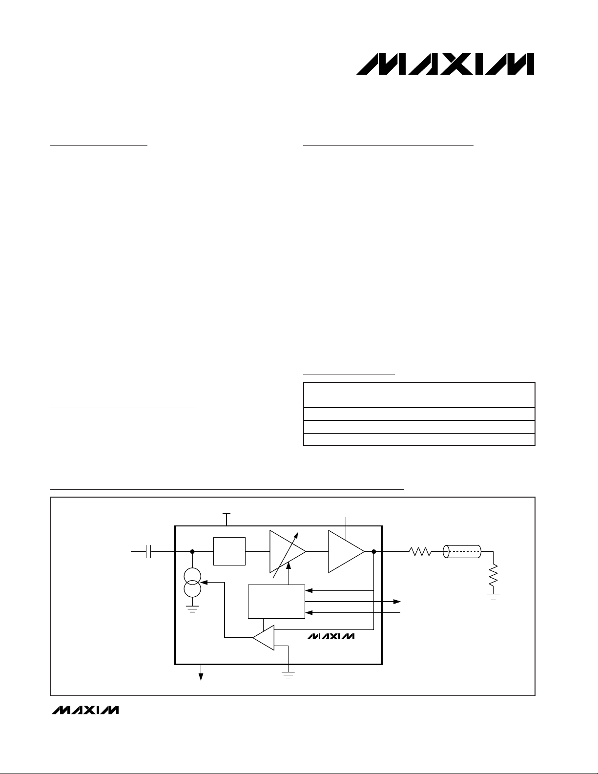
The MAX7450/MAX7451/MAX7452 complete front-end
video-signal conditioners are designed to improve the
quality of standard-definition video signals. The devices
restore the DC level of the video input, correct for
amplitude errors up to ±6dB, detect fault conditions,
and filter out-of-band noise. The MAX7450/MAX7451/
MAX7452 optimize the signal quality for further video
processing through a crosspoint switch or video
decoder (ADC). Each device integrates an input video
clamp, automatic gain control (AGC), loss-of-sync
(LOS) detector, and an out-of-band noise/lowpass filter.
These devices also incorporate a user-selectable
buffer gain (0 or +6dB) and an AGC-disable function.
The MAX7450 and MAX7451 operate from dual power
supplies of ±5V or ±3.3V respectively, and they restore
the video blanking level to GND. The MAX7452 operates
from a single +5V supply and features a user-adjustable
clamp level.
The devices are available in an 8-pin SO package with
an exposed pad and are specified for operation over
the extended (-40°C to +85°C) temperature range.
Applications
Signal Conditioner for Standard-Definition
Video Inputs
Security Video Systems
Video-Switching Systems
Features
♦ Back-Porch Clamp to GND (MAX7450/MAX7451)
♦ Adjustable Back-Porch Clamp (MAX7452)
♦ Automatic Gain Control (±6dB Range) Normalizes
Signals to Standard Video Level
♦ Input Fault Detection with LOS Output
♦ Inherent 50Hz/60Hz Input Rejection of 60dB
♦ Single-Supply Operation: MAX7452 (+5V)
♦ Out-of-Band Noise Filter
♦ Output Buffer Drives Standard 150Ω Video Load
with 0dB or +6dB Gain
♦ Dual-Supply Operation
MAX7450 (±5V)
MAX7451 (±3.3V)
♦ Tiny 8-Pin SO Package
MAX7450/MAX7451/MAX7452
Video-Signal Conditioners with AGC and
Back-Porch Clamp
________________________________________________________________ Maxim Integrated Products 1
Ordering Information
19-3267; Rev 0; 4/04
For pricing, delivery, and ordering information, please contact Maxim/Dallas Direct! at
1-888-629-4642, or visit Maxim’s website at www.maxim-ic.com.
PART
TEMP RANGE
PIN-
SUPPLY
VOLTAGE (V)
MAX7450ESA
±5
MAX7451ESA*
±3.3
MAX7452ESA
+5
MAX7450
MAX7451
NOISE
FILTER
V
CC
V
SS
75Ω
75Ω
LOS
SYNC SEPARATOR
AND AMPLITUDE
DETECTOR
AGCD
IN
OUT
VIDEO
INPUT
GND
±6dB
0 OR +6dB
GAIN SET (0dB OR +6dB)
Functional Diagram
*Future product—contact factory for availability.
**EP = Exposed pad.
PACKAGE
-40°C to +85°C8 SO-EP**
-40°C to +85°C8 SO-EP**
-40°C to +85°C8 SO-EP**
Page 2
MAX7450/MAX7451/MAX7452
Video-Signal Conditioners with AGC and
Back-Porch Clamp
2 _______________________________________________________________________________________
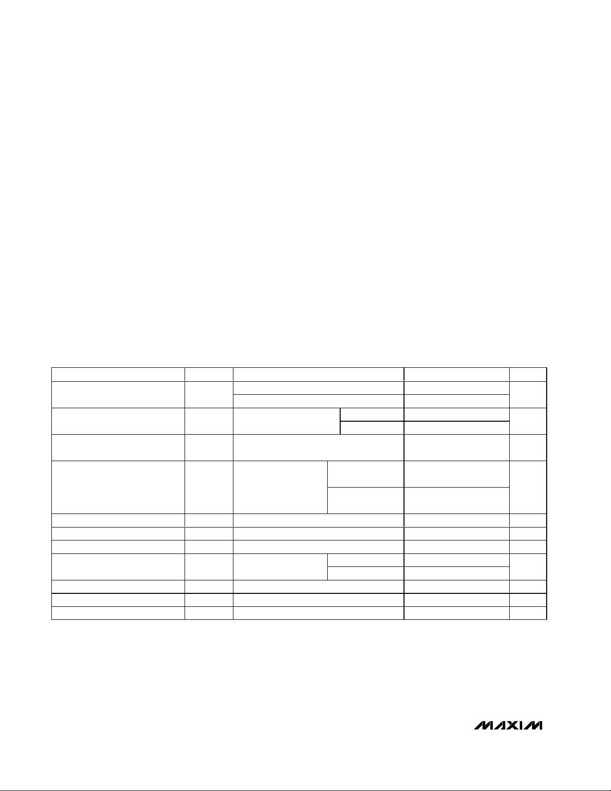
ABSOLUTE MAXIMUM RATINGS
ELECTRICAL CHARACTERISTICS
(V
SUPPLY
= ±5V ±5% (MAX7450), V
SUPPLY
= ±3.3V ±5% (MAX7451), V
SUPPLY
= +5V ±5% (MAX7452), RL=150Ω to GND, CL = 0 to
20pF, GSET = 1, AGCD = 1, T
A
= T
MIN
to T
MAX
, unless otherwise noted. Typical values are at TA = +25°C.)
Stresses beyond those listed under “Absolute Maximum Ratings” may cause permanent damage to the device. These are stress ratings only, and functional
operation of the device at these or any other conditions beyond those indicated in the operational sections of the specifications is not implied. Exposure to
absolute maximum rating conditions for extended periods may affect device reliability.
VCCto GND
MAX7450/MAX7452...........................................................+6V
MAX7451 ...........................................................................+4V
V
SS
to GND
MAX7450.............................................................................-6V
MAX7451.............................................................................-4V
OUT
MAX7450/MAX7451 ..........................................-2.5V to +3.5V
MAX7452................................................-0.3V to (V
CC
+ 0.3V)
GSET, AGCD, LOS.....................................-0.3V to (V
CC
+ 0.3V)
All Other Pins
MAX7450/MAX7451...................(-0.3V + V
SS
) to (VCC+ 0.3V)
MAX7452................................................-0.3V to (V
CC
+ 0.3V)
Maximum Current into Any Pin ............……………………±50mA
Continuous Power Dissipation (T
A
= +70°C)
8-Pin SO (derate 18.9mW/°C above +70°C)..............1509mW
Operating Temperature Range ...........................-40°C to +85°C
Storage Temperature Range .............................-65°C to +150°C
Junction Temperature......................................................+150°C
Lead temperature (soldering, 10s) ..................................+300°C
PARAMETER
CONDITIONS
UNITS
MAX7450/MAX7451, relative to GND
Clamp Accuracy
MAX7452, relative V
BPLVL
= 1.5V
mV
GSET = 0 1.0 3.0
Back-Porch Level Input Range V
BPLVL
MAX7452
GSET = 1 1.2 2.4
V
Clamp Response Time t
CLAMP
Blanking level at the output to 1% of final
value
70
Lines
GSET = 0, relative
to V
OUT
= 1V
P-P
AGC Accuracy
AGCD = 0,
GSET = 1, relative
to V
OUT
= 2V
P-P
%
AGC Input Range AGCD = 0, relative to VIN = 1V
P-P
dB
Gain Flatness G
F
f = 5MHz relative to 100kHz
dB
Noise-Filter Cutoff Fc 10
MHz
GSET = 0
1
Low-Frequency Gain f = 100kHz
GSET = 1
2
V/V
Group-Delay Deviation ∆t
G
3.58/4.43MHz relative to 100kHz 15 ns
Differential Gain dG
0.2 0.6 %
Differential Phase dθ
0.2 0.6
Degrees
SYMBOL
MIN TYP MAX
±50
±50
VIN = 0.5V
Five-step modulated staircase (VIN = 1V
Five-step modulated staircase (VIN = 1V
to 2V
P-P
P-P
)
P-P
)
P-P
-6.0 +6.0
-0.3 +0.3
0.95
1.85
±10
±10
1.05
2.05
Page 3
MAX7450/MAX7451/MAX7452
Video-Signal Conditioners with AGC and
Back-Porch Clamp
_______________________________________________________________________________________ 3
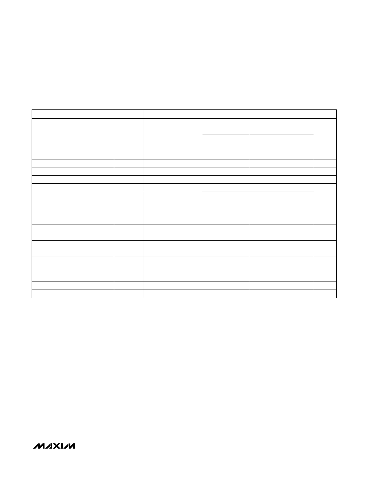
ELECTRICAL CHARACTERISTICS (continued)
(V
SUPPLY
= ±5V ±5% (MAX7450), V
SUPPLY
= ±3.3V ±5% (MAX7451), V
SUPPLY
= +5V ±5% (MAX7452), RL=150Ω to GND, CL = 0 to
20pF, GSET = 1, AGCD = 1, T
A
= T
MIN
to T
MAX
, unless otherwise noted. Typical values are at TA = +25°C.)
PARAMETER
CONDITIONS
UNITS
GSET = 0,
V
OUT
= 1V
P-P
68
Signal-to-Noise Ratio SNR
Output signal
peak-to-peak to RMS
GSET = 1,
V
OUT
= 2V
P-P
65
dB
Line Time Distortion H
DIST
18µs, 100 IRE bar 0.2 %
Field Time Distortion V
DIST
130 lines, 18µs, 100IRE bar 0.5 %
Input Leakage Current I
IN
15µA
Output Dynamic Range VIN = 1V
P-P
, dG / dP < 3% / degrees 2 2.4
V
P-P
AGCD = 1 30
Power-Supply Rejection Ratio PSRR
V
CC
+ 100mV
P-P
,
f = 3.5MHz
AGCD = 0 with
maximum gain
20
dB
MAX7450 35
Supply Current
MAX7452 20
mA
Logic-High Input V
IH
0.7 x
V
Logic-Low Input V
IL
0.3 x
V
Logic-High Output V
OH
I
SOURCE
= 500µA
V
CC
-
0.5
V
Logic-Low Output V
OL
I
SINK
= 500µA 0.4 V
Input Current Logic-High I
IH
Logic input sink 10 µA
Input Current Logic-Low I
IL
Logic input source 10 µA
SYMBOL
noise (100Hz to 5MHz)
MIN TYP MAX
V
CC
V
CC
Page 4
MAX7450/MAX7451/MAX7452
Video-Signal Conditioners with AGC and
Back-Porch Clamp
4 _______________________________________________________________________________________
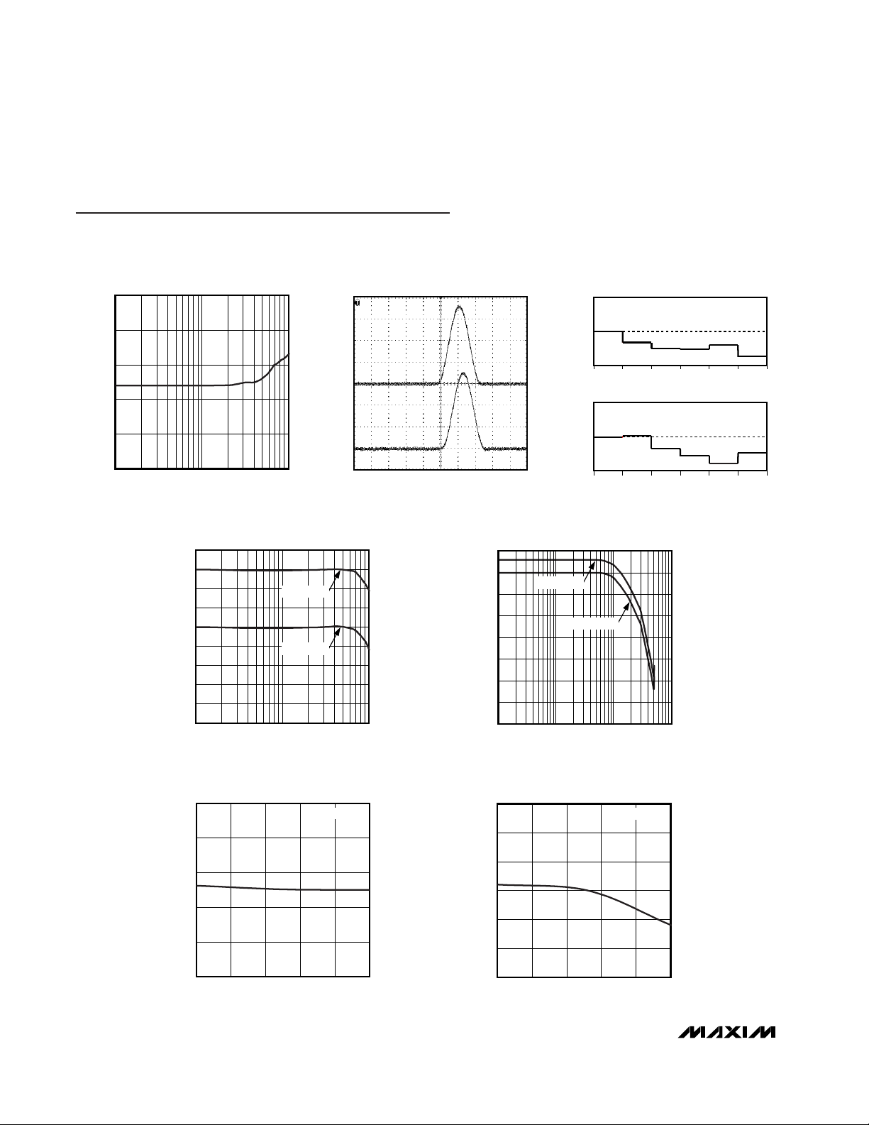
Typical Operating Characteristics
V
SUPPLY
= ±5V ±5% (MAX7450), V
SUPPLY
= ±3.3V ±5% (MAX7451), V
SUPPLY
= +5V ±5% (MAX7452), RL= 150Ω to GND, CL = 0 to
20pF, GSET = 1, AGCD = 1. T
A
= +25°C, unless otherwise noted.
GROUP DELAY vs. FREQUENCY
MAX7450 toc01
FREQUENCY (MHz)
GROUP DELAY (ns)
1
20
30
40
50
60
10
0.1 10
2T RESPONSE
MAX7450 toc02
t = 200ns/div
IN
200mV/div
OUT
200mV/div
DIFFERENTIAL GAIN
MAX7450 toc03
DIFFERENTIAL PHASE (DEGREES)
1st 3rd2nd 4th 5th
6th
DIFFERENTIAL GAIN (%)
0.2
0.4
0
-0.2
-0.4
0.2
0.1
0.3
0
-0.2
-0.1
-0.3
DIFFERENTIAL PHASE
1st 3rd2nd 4th 5th
6th
PASSBAND AMPLITUDE vs. FREQUENCY
MAX7450 toc04
FREQUENCY (MHz)
AMPLITUDE (dB)
1
-8
-6
-4
-2
0
2
4
6
8
-10
0.1 10
GAIN = 2V / V
GAIN = 1V / V
AMPLITUDE vs. FREQUENCY
MAX7450 toc05
FREQUENCY (MHz)
AMPLITUDE (dB)
110
-70
-60
-50
-40
-30
-20
-10
0
10
0.1 100
GAIN = 1V / V
GAIN = 2V / V
SUPPLY CURRENT vs. TEMPERATURE
MAX7450 toc06
TEMPERATURE (°C)
SUPPLY CURRENT (mA)
603510-15
27
29
31
33
35
25
-40 85
MAX7450
BACK-PORCH VOLTAGE
vs. TEMPERATURE
MAX7450 toc07
TEMPERATURE (°C)
BACK-PORCH VOLTAGE (mV)
603510-15
-5
-4
-3
-2
-1
0
-6
-40 85
MAX7450
Page 5
MAX7450/MAX7451/MAX7452
Video-Signal Conditioners with AGC and
Back-Porch Clamp
_______________________________________________________________________________________ 5
PIN
MAX7450/
FUNCTION
11
Positive Power Supply. Connect +5V to VCC for the MAX7450/MAX7452. Connect +3.3V to V
CC
for the MAX7451. Bypass to GND with 1µF and 0.1µF capacitors as close to the pin as possible.
22IN Video Input. AC-couple video signal through a 0.1µF capacitor.
33
Ground
4—
Negative Power Supply. Connect -5V to V
SS
for the MAX7450. Connect -3.3V to VSS for the
MAX7451. Bypass to GND with 1µF and 0.1µF capacitors as close to the pin as possible.
—4
Back-Porch Level Input. When gain = 2V/V (GSET = 1), output back-porch level is equal to
BPLVL input. When gain = 1V/V (GSET = 0), output back-porch level is equal to V
BPLVL
/1.5.
55
Automatic Gain-Control Disable Input. Disable AGC by driving AGCD to VCC. Enable AGC by
driving AGCD to GND.
66
Video Output
77
Gain-Setting Input. Drive GSET high to set buffer gain to +6dB. Drive GSET low to set buffer
gain to 0dB.
88
Loss-of-Sync Logic Output. LOS is high when video sync is lost for more than 15 horizontal
lines. LOS goes low when video sync is present.
——EP Exposed Pad. Connect to V
SS
(MAX7450/MAX7451). Connect to GND (MAX7452).
Pin Description
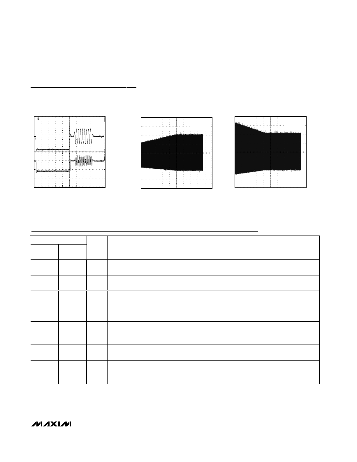
OUTPUT BACK-PORCH LEVEL (MAX7450)
MAX7450 toc08
1µs
IN
AC-COUPLED
200mV/div
OUT
200mV/div
BACK-PORCH = 0V
AGC RESPONSE ENVELOPE (VIN = 0.5V
P-P
)
MAX7450 toc09
400ms/div
500mV/div
AGCD = 0
V
OUT
= 2V
P-P
AGC RESPONSE ENVELOPE (VIN = 2V
P-P
)
MAX7450 toc10
400ms/div
500mV/div
AGCD = 0
V
OUT
= 2V
P-P
Typical Operating Characteristics (continued)
V
SUPPLY
= ±5V ±5% (MAX7450), V
SUPPLY
= ±3.3V ±5% (MAX7451), V
SUPPLY
= +5V ±5% (MAX7452), RL= 150Ω to GND, CL = 0 to
20pF, GSET = 1, AGCD = 1. T
A
= +25°C, unless otherwise noted.
MAX7451
MAX7452
NAME
V
CC
GND
V
SS
BPLVL
AGCD
OUT
GSET
LOS
Page 6

MAX7450/MAX7451/MAX7452
Video-Signal Conditioners with AGC and
Back-Porch Clamp
6 _______________________________________________________________________________________
Detailed Description
As shown in Figure 1, the devices include a 2nd-order
lowpass filter intended to reject out-of-band noise. The
MAX7450/MAX7451 clamp the back-porch voltage to
ground, and the MAX7452 clamps to a user-supplied
reference voltage. These devices also include an automatic gain control (AGC), which automatically adjusts
the gain to ensure the sync amplitude is normalized to
a standard video level; an AGC disable function; and
an output driver that drives a standard video load
(150Ω) with a full 2V
P-P
video signal (GSET = 1) or 1V
P-
P
video signal (GSET = 0).
The clamp and the AGC work concurrently. Interaction
between the two different control loops is eliminated by
the large difference in time constants. The time constant of the clamp settles within 100 lines, while the
AGC loop is digitally stepped so that it settles between
1000–64,000 lines.
The AGC control works independently of the gain setting of the output buffer. The overall gain is the multiplication of the AGC gain and the output buffer gain. The
maximum overall gain is +12dB and the minimum gain
is -6dB.
Back-Porch Clamp
The MAX7450/MAX7451/MAX7452 feature a backporch clamp to set the output blanking level. The
devices sense the voltage during back porch and feed
back into a control system. The control system provides
the appropriate DC-level shift to clamp the output to
ground (MAX7450/MAX7451) or to a voltage set by
V
BPLVL
(MAX7452). This restores the DC level for further video processing such as on-screen display (OSD)
insertion and analog-to-digital conversion. The backporch clamp to ground also eliminates the need for
large output-coupling capacitors that can introduce
unwanted line-time distortion (tilt) and cost. This can
also reduce board space. The feedback network and
the on-chip capacitors introduce a finite settling time
after power-up or after any dramatic shift in input voltage (see the Electrical Characteristics section).
Back-Porch Level Input (MAX7452)
The MAX7452 features an adjustable back-porch level
at the output as shown in Figure 1. V
BPLVL
sets the
back-porch clamp level. The back-porch clamp-output
level is defined by the following equations.
GSET = 1 (Gain = 2V / V), V
BACKPORCHLEVEL
= V
BPLVL
GSET = 0 (Gain = 1V / V), V
BACKPORCHLEVEL
=
V
BPLVL
/ 1.5
MAX7452
NOISE
FILTER
V
CC
75Ω
75Ω
LOS
SYNC SEPARATOR
AND AMPLITUDE
DETECTOR
AGCD
IN
OUT
VIDEO
INPUT
BPLVL
±6dB
0 OR +6dB
GAIN SET (0dB OR +6dB)
GND
Figure1. MAX7452 Functional Diagram
Page 7
MAX7450/MAX7451/MAX7452
Video-Signal Conditioners with AGC and
Back-Porch Clamp
_______________________________________________________________________________________ 7
Automatic Gain Control (AGC)
The MAX7450/MAX7451/MAX7452 have an integrated
automatic gain-control circuit to ensure the sync amplitude is normalized to the standard level, thus normalizing
the overall amplitude to a standard level. The accuracy
of the normalized amplitude assumes the ratio of active
video to sync amplitude is correct in the input video signal. The gain is adjusted automatically by detecting and
comparing the amplitude of the sync pulse to a fixed
internal reference. If the sync amplitude is less than this
value, the overall gain is increased until the sync amplitude equals this reference. However, if the sync amplitude is high, the overall gain is reduced accordingly.
Disable the AGC loop by driving AGCD high.
When designing the overall system, it is important to note
that the AGC can correct for termination problems. First,
disable the AGC and verify that the terminations are correct, and then enable the AGC for proper operation.
Output Buffer
The output buffer of the MAX7450/MAX7451/MAX7452
is designed to drive either standard video loads or
high-impedance loads, independent of the buffer gain.
Logic levels on GSET and AGCD set the gain of the
MAX7450/MAX7451/MAX7452. Table 1 shows the different gain-setting configurations.
Noise Filter
The MAX7450/MAX7451/MAX7452 feature a simple 2ndorder lowpass filter to reject out-of-band noise that may
be introduced by the long cable connection between the
cameras and the switching matrix.
LOS Detector
The LOS detector of the MAX7450/MAX7451/MAX7452
outputs a logic high when the sync is not present (loss
of video signal) for at least 15 horizontal lines on the
input. This can be used to indicate a fault condition of
the camera or cable.
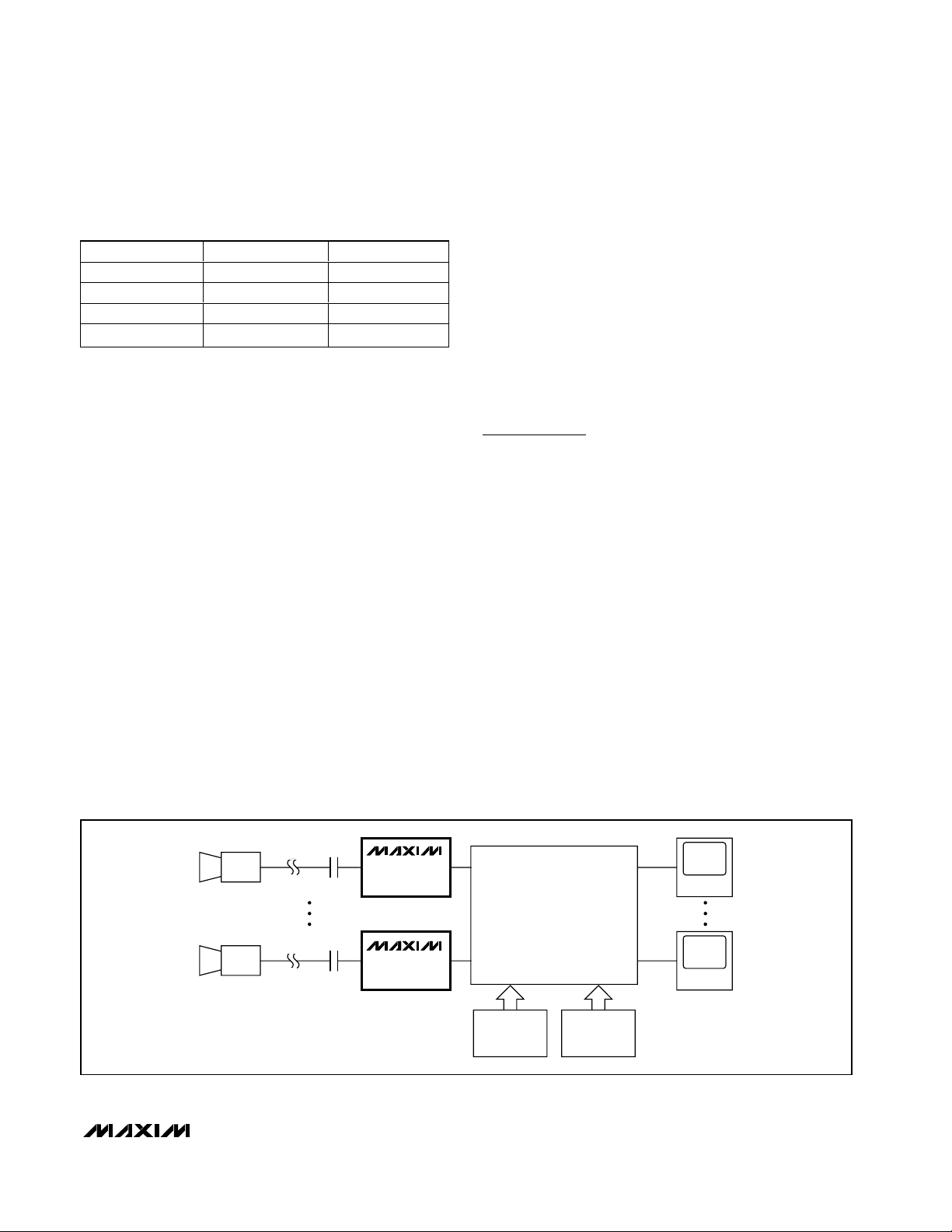
Applications Information
Connecting the MAX7450/MAX7451 to a
Crosspoint Switch
The MAX7450/MAX7451/MAX7452 are designed to
directly interface to a video crosspoint switching device
such as those used in security systems (see Figure 2).
The MAX7450/MAX7451 clamp the video output to
GND, making the devices an ideal interface to the
MAX4358 crosspoint switches and the MAX4455 OSD.
The MAX7450/MAX7451 and the MAX4455 have their
outputs referenced to ground, ensuring the amplitudes
and the brightness of the OSD relative to the video
signal are accurate.
Interfacing the MAX7452 to an ADC
The MAX7452 can be directly connected to an ADC or
video decoder as shown in Figure 3. The video output
of the MAX7452 is DC-coupled to a single-ended video
input on the ADC. The voltage on the BPLVL pin sets
the black level of the video signal at the output of the
MAX7452. Use a stable voltage reference for the
BPLVL voltage, ideally the same reference that is used
AGCD GSET OUTPUT
001V
P-P
fixed
012V
P-P
fixed
10V
OUT
= V
IN
11V
OUT
= 2V
IN
Table 1. Gain-Control Setings
MAX7450
MAX7451
MAX7450
MAX7451
CAM 1
MAX4358
32 x 16
CROSSPOINT
MAX4455
OSD
MAX4455
OSD
CAM 32
MONITOR 1
MONITOR 16
Figure 2. MAX7450/MAX7451 in a 32 x 16 Crosspoint Application
Page 8

MAX7450/MAX7451/MAX7452
Video-Signal Conditioners with AGC and
Back-Porch Clamp
8 _______________________________________________________________________________________
for the analog-to-digital conversion. This voltage must
be scaled by a ratio of two resistors to set the black
level of the video signal to the appropriate level (to
match the input range of the converter).
If the ADC or video decoder has a built-in clamp circuit,
the output of the MAX7452 must be AC-coupled into
the ADC with the capacitor value recommended for the
converter. In this situation, set the BPLVL on the
MAX7452 to the midpoint of the specified range for
optimum performance. In addition, the stability of this
voltage is not critical, provided that it stays within the
specified range.
Power-Supply Bypassing and Layout
Bypass all supply pins to GND with 0.1µF and 1µF
capacitors. These capacitors filter higher frequencies in
the MHz range. Place all external components as close to
the devices as possible. Connect EP to VSSfor the
MAX7450/MAX7451. Connect EP to GND for the
MAX7452. Placing the IC onto a copper area the size of
the pad is recommended for proper power dissipation.
Refer to the MAX7450 Evaluation Kit for a proven PCboard layout example.
Chip Information
TRANSISTOR COUNT: 6316
PROCESS: BiCMOS
MAX7452
NOISE
FILTER
V
CC
V
SS
LOS
SYNC SEPARATOR
AND AMPLITUDE
DETECTOR
AGCD
IN
OUT
VIDEO
INPUT
BPLVL
±6dB
0 OR +6dB
GAIN SET (0dB OR +6dB)
ADC
DSP
REF
VIDEO DECODER
Figure 3. MAX7452 Interfaced to a Video Decoder
OUT
AGCD
V
SS
(MAX7450/MAX7451)
BPLVL (MAX7452)
1
2
87LOS
GSETIN
GND
V
CC
SO-EP*
TOP VIEW
*CONNECT EP TO V
SS
FOR THE MAX7450/MAX7451
3
4
6
5
MAX7450
MAX7451
MAX7452
Pin Configuration
Page 9

MAX7450/MAX7451/MAX7452
Video-Signal Conditioners with AGC and
Back-Porch Clamp
Maxim cannot assume responsibility for use of any circuitry other than circuitry entirely embodied in a Maxim product. No circuit patent licenses are
implied. Maxim reserves the right to change the circuitry and specifications without notice at any time.
Maxim Integrated Products, 120 San Gabriel Drive, Sunnyvale, CA 94086 408-737-7600 _____________________ 9
© 2004 Maxim Integrated Products Printed USA is a registered trademark of Maxim Integrated Products.
Package Information
(The package drawing(s) in this data sheet may not reflect the most current specifications. For the latest package outline information,
go to www.maxim-ic.com/packages
.)
8L, SOIC EXP. PAD.EPS
B
1
1
21-0111
PACKAGE OUTLINE
8L SOIC, .150" EXPOSED PAD
 Loading...