

Page 1
General Description
The MAX6791–MAX6796 ultra-low-quiescent-current,
single-/dual-output linear regulators are ideal for automotive applications. The devices offer a wide 5V to 72V
operating input range, allowing them to withstand automotive load-dump conditions while consuming only
68µA. The MAX6791–MAX6794 are dual-output regulators capable of supplying up to 150mA per output. The
MAX6795/MAX6796 offer a single output capable of
delivering up to 300mA. These devices offer standard
output-voltage options (5V, 3.3V, 2.5V, or 1.8V) and can
be adjusted to any voltage from 1.8V to 11V. The
MAX6791–MAX6794 also offer a fixed 5V output.
All devices feature a push-pull or open-drain, active-low
RESET output with a fixed output reset threshold that is
92.5%/87.5% of the regulator output OUT/OUT1. The
reset output asserts low when OUT/OUT1 drops below
the reset threshold and remains low for the fixed or
capacitor-adjustable reset timeout period after
OUT/OUT1 exceeds the reset threshold.
The MAX6791–MAX6796 provide a watchdog input that
monitors a pulse train from the microprocessor (µP) and
generates reset pulses if the watchdog input remains
high or low for a duration longer than the watchdog
timeout period. All devices are available with either a
fixed watchdog timeout period of 280ms (min) or a period adjustable with an external capacitor. The
MAX6791/MAX6792 feature a windowed watchdog
timeout period with selectable window ratio. The watchdog feature can be disabled.
The MAX6791–MAX6794 provide dual enable inputs
(ENABLE1 and ENABLE2) that control each regulator
independently. The single-output MAX6795/MAX6796
feature one enable input (ENABLE).
All devices include a hold input (HOLD) that aids the
implementation of a self-holding circuit without requiring external components. Once the regulator is
enabled, setting HOLD low forces the regulator to
remain on even if ENABLE/ENABLE1 is subsequently
set low. Releasing HOLD shuts down the regulator.
The MAX6791–MAX6796 are available in a small, thermally enhanced TQFN package. The 5mm x 5mm
package dissipates up to 2.7W, supporting continuous
regulator operation during high ambient temperatures,
high battery voltage, and high load-current conditions.
The MAX6791–MAX6796 are specified for a -40°C to
+125°C operating temperature range.
Applications
Automotive
Features
♦ Low 68µA Quiescent Current
♦ Wide 5V to 72V Supply Voltage Range
♦ Output Current
Single Output Up to 300mA
Dual Outputs Up to 150mA per Output
♦ Low Dropout Voltage
420mV (typ) at 100mA (Single)
840mV (typ) at 100mA (Dual)
♦ Fixed Output-Voltage Options: 5V, 3.3V, 2.5V,
1.8V, or Adjustable Output (from 1.8V to 11V)
♦ ENABLE and HOLD Functionality
♦ RESET Output: Open Drain or Push-Pull
♦ Internally Fixed (35µs, 3.125ms, 12.5ms, 50ms, or
200ms) or Capacitor-Adjustable Reset Timeout
Periods
♦ Internally Fixed or Capacitor-Adjustable
Watchdog Timeout Periods
♦ Windowed (Minimum/Maximum) Watchdog Timer
Options (MAX6791/MAX6792)
♦ Watchdog Disable Feature
♦ Thermal, Short-Circuit, and Output Overvoltage
Protection
♦ Fully Specified from -40°C to +125°C
♦ Small, Thermally Enhanced, 5mm x 5mm TQFN
MAX6791–MAX6796
High-Voltage, Micropower, Single/Dual
Linear Regulators with Supervisory Functions
________________________________________________________________ Maxim Integrated Products 1
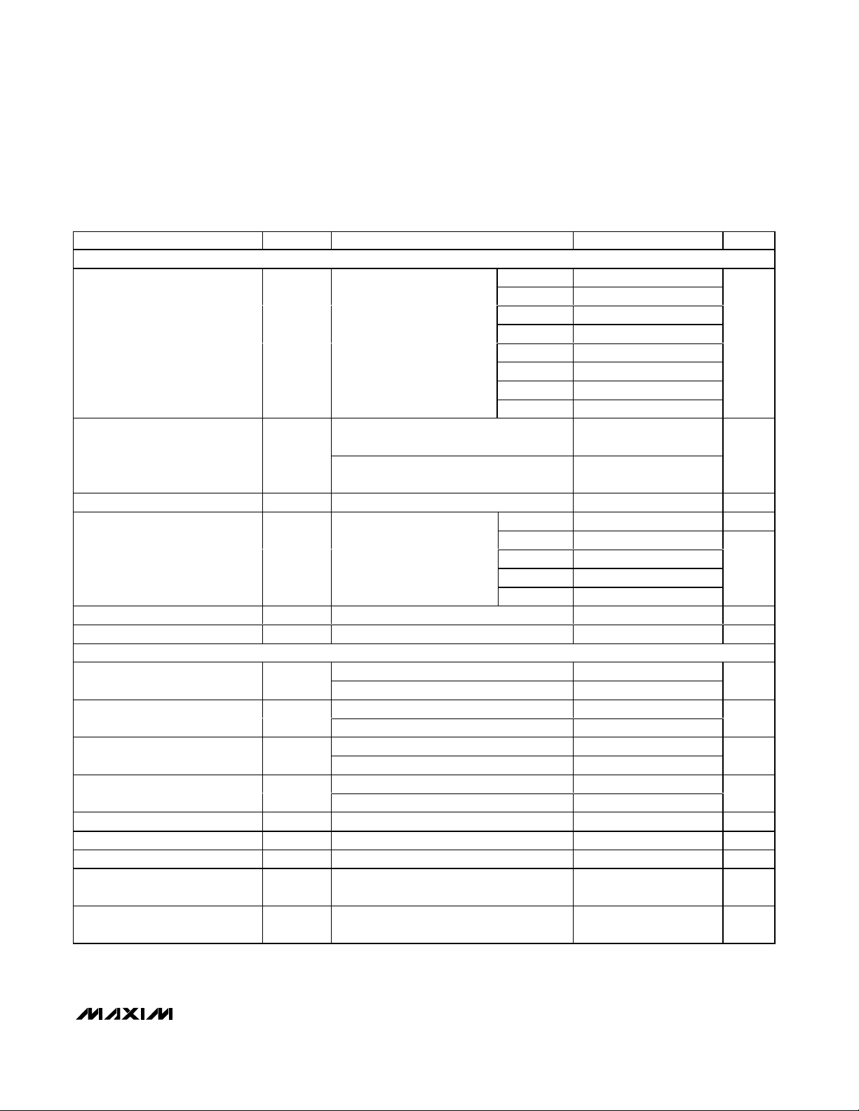
Ordering Information
19-3875; Rev 0; 11/05
For pricing, delivery, and ordering information, please contact Maxim/Dallas Direct! at
1-888-629-4642, or visit Maxim’s website at www.maxim-ic.com.
+Denotes lead-free package.
For tape-and-reel, add a T after the “+.” Tape-and-reel are
offered in 2.5k increments. The first placeholder “_” designates
preset output-voltage option and preset reset threshold level;
see Table 1. The second placeholder “_ ” designates the reset
timeout period; see Table 2. For example, the MAX6791TPSD3+
indicates a 3.3V output voltage with a reset threshold of 87.5%
at nominal voltage and a 50ms reset timeout period. Samples
are generally held in stock. Nonstandard versions require a 2.5k
minimum order quantity.
EVALUATION KIT
AVAILABLE
PART
TEMP
RANGE
PIN-
PKG
CODE
M A X6 7 9 1 TP _D _+
T2055-4
M A X6 7 9 2 TP _D _+
T2055-4
M A X6 7 9 3 TP _ D _+
T2055-4
M A X6 7 9 4 TP _ D _+
T2055-4
M A X6 7 9 5 TP _ D _+
T2055-4
M A X6 7 9 6 TP _D _+
T2055-4
Typical Application Circuit, Pin Configurations, and Selector
Guide appear at end of data sheet.
PACKAGE
-40°C to +125°C 20 TQFN
-40°C to +125°C 20 TQFN
-40°C to +125°C 20 TQFN
-40°C to +125°C 20 TQFN
-40°C to +125°C 20 TQFN
-40°C to +125°C 20 TQFN
Page 2
MAX6791–MAX6796
High-Voltage, Micropower, Single/Dual Linear
Regulators with Supervisory Functions
2 _______________________________________________________________________________________
ABSOLUTE MAXIMUM RATINGS
ELECTRICAL CHARACTERISTICS
(VIN= 14V, CIN= 1µF, C
OUT
= 10µF, TA= TJ= -40°C to +125°C, unless otherwise noted. Typical values are at TA= TJ= +25°C.)
(Note 1)
Stresses beyond those listed under “Absolute Maximum Ratings” may cause permanent damage to the device. These are stress ratings only, and functional
operation of the device at these or any other conditions beyond those indicated in the operational sections of the specifications is not implied. Exposure to
absolute maximum rating conditions for extended periods may affect device reliability.
(All pins referenced to GND, unless otherwise noted.)
IN to GND ...............................................................-0.3V to +80V
ENABLE, ENABLE1, ENABLE2, PFI,
GATEP to GND ...........................................-0.3V to (IN + 0.3V)
GATEP to IN ...........................................................-12V to +0.3V
OUT, OUT1, OUT2, PFO, RESET (open-drain versions),
CSRT, CSWT .......................................................-0.3V to +12V
HOLD, RESET (push-pull versions), WDI, WDS0, WDS1,
WD-DIS, SET, SET1......................-0.3V to (OUT/OUT1 + 0.3V)
OUT, OUT1, OUT2 Short Circuit
to GND....................................................................Continuous
Maximum Current (all pins except IN and OUT_)...............50mA
Continuous Power Dissipation (T
A
= +70°C)
20-Pin TQFN (derate 33.3mW/°C above +70°C) .....2666.7mW
Operating Temperature Range (T
A
)..................-40°C to +125°C
Junction Temperature (T
J
) .................................................150°C
Storage Temperature Range .............................-65°C to +150°C
Lead Temperature (soldering, 10s) .................................+300°C
PARAMETER
CONDITIONS
UNITS
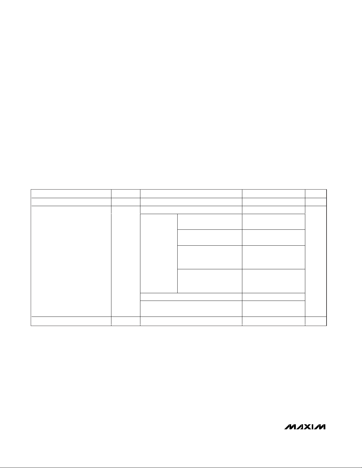
Supply Voltage Range V
IN
572V
Regulators on (I
LOAD
= 0mA), VIN = 8V 68 85
VIN = 8V, I
LOAD
= 300mA
(MAX6795/MAX6796)
220
VIN = 14V, I
LOAD
= 100mA
(MAX6795/MAX6796)
160
VIN = 8V, I
LOAD1
= I
LOAD2
= 150mA
(MAX6791–MAX6794)
220
Regulators on,
OUT/OUT1 =
OUT2 = 5V
V
IN
= 14V, I
LOAD1
=
I
LOAD2
= 50mA
(MAX6791–MAX6794)
160
Regulators on (I
LOAD
= 0mA), VIN = 42V 74 95
Supply Current I
IN
Regulators on (I
LOAD
= 20mA, total)
OUT1/OUT2/OUT = 5V, V
IN
= 42V
170
µA
Shutdown Supply Current I
SHDN
Regulators off, V
IN
= 14V 27 45 µA
SYMBOL
MIN TYP MAX
130
100
130
100
100
Page 3
MAX6791–MAX6796
High-Voltage, Micropower, Single/Dual Linear
Regulators with Supervisory Functions
_______________________________________________________________________________________ 3
ELECTRICAL CHARACTERISTICS (continued)
(VIN= 14V, CIN= 1µF, C
OUT
= 10µF, TA= TJ= -40°C to +125°C, unless otherwise noted. Typical values are at TA= TJ= +25°C.)
(Note 1)
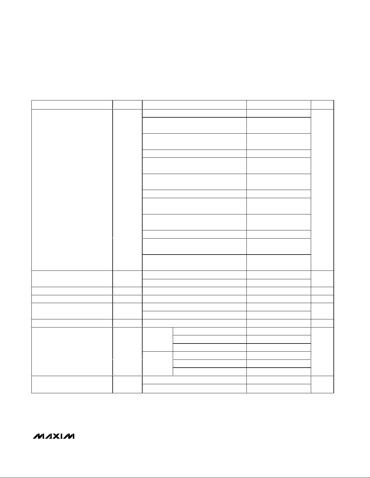
PARAMETER
CONDITIONS
UNITS
L/M, I
LOAD
= I
LOAD1
= 1mA
V
IN
= 8V
VIN = 8V
5
T/S, I
LOAD
= I
LOAD1
= 1mA
V
IN
= 6V
T/S, I
LOAD
= 300mA (MAX6795/MAX6796),
V
IN
= 6V
3.3
Z/Y, I
LOAD
= I
LOAD1
= 1mA
Z/Y, I
LOAD
= 150mA (MAX6791–MAX6794),
V
IN
= 5.5V
Z/Y, I
LOAD
= 300mA (MAX6795/MAX6796),
V
IN
= 5.5V
2.5
W/V, I
LOAD
= I
LOAD1
= 1mA
W/V, I
LOAD
= 150mA (MAX6791–MAX6794),
V
IN
= 5V
Output Voltage
V
OUT
/
V
OUT1
W/V, I
LOAD
= 300mA (MAX6795/MAX6796),
V
IN
= 5V
1.8
V
I
LOAD2
= 1mA
Output Voltage
(MAX6791–MAX6794)
V
OUT2
I
LOAD2
= 150mA
V
SET/SET1 Threshold Voltage V
SET
I
LOAD
= I
LOAD1
= 1mA, OUT/OUT1 = 5V
V
Adjustable Output Voltage V
OUT
1.8
V
SET/SET1 rising
Dual-Mode™ SET Threshold
SET/SET1 falling 62
mV
SET/SET1 Input Current SET/SET1 = 1V, VIN = 11V
nA
L/M, I
LOAD
= 20mA (Note 2)
84 130
L/M, I
LOAD
= 10mA (Note 2) 84 130
Dropout Voltage ∆V
DO
(MAX6791–
mV
M AX6795/M AX6796, i nfer red fr om d r opout test
Guaranteed Output Current
(Note 4)
MAX6791–MAX 6794, inferr ed from d rop out test
mA
Dual Mode is a trademark of Maxim Integrated Products, Inc.
SYMBOL
L/M, I
LOAD
L/M, I
LOAD
T/S, I
LOAD
(MAX6795/
MAX6796)
MAX6794)
= 150mA (MAX6791–MAX6794),
= 300mA (MAX6795/MAX6796),
= 150mA (MAX6791–MAX6794),
L/M, I
T/S, I
L/M, I
T/S, I
= 300mA (Note 2)
LOAD
= 300mA (Note 3) 1700 2400
LOAD
= 150mA (Note 2) 1000 1800
LOAD
= 150mA (Note 3) 1700 2400
LOAD
MIN TYP MAX
4.858 4.974 5.090
4.811 4.945 5.078
4.850
3.206 3.282 3.360
3.175 3.263 3.351
3.201
2.429 2.487 2.546
2.405 2.472 2.539
2.425
1.748 1.791 1.832
1.731 1.780 1.828
1.746
4.858 4.974 5.090
4.811 4.945 5.079
1.207 1.2315 1.256
124
-100 +100
1200
300
150
5.150
3.399
2.575
1.854
11.0
1800
Page 4
MAX6791–MAX6796
High-Voltage, Micropower, Single/Dual Linear
Regulators with Supervisory Functions
4 _______________________________________________________________________________________
ELECTRICAL CHARACTERISTICS (continued)
(VIN= 14V, CIN= 1µF, C
OUT
= 10µF, TA= TJ= -40°C to +125°C, unless otherwise noted. Typical values are at TA= TJ= +25°C.)
(Note 1)
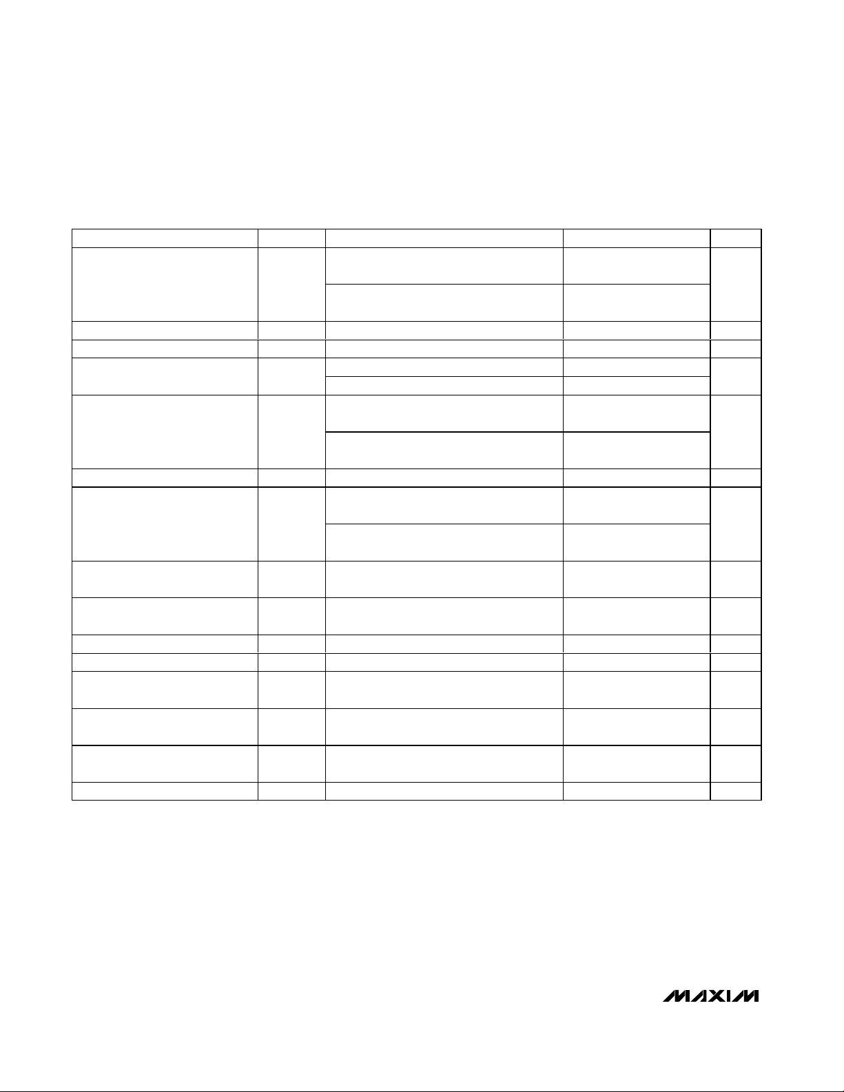
PARAMETER
SYMBOL
CONDITIONS
MIN
TYP
MAX
UNITS
MAX6795/MAX6796, output shorted,
V
IN
= 6V
Short-Circuit Output Current Limit
(Note 4)
MAX6791–MAX6794, output shorted,
V
IN
= 6V
mA
Thermal-Shutdown Temperature
°C
Thermal-Shutdown Hysteresis 20 °C
8V ≤ VIN ≤ 72V, I
LOAD
= 1mA 1
Line Regulation
8V ≤ V
IN
≤ 72V, I
LOAD
= 10mA 1
% of
V
OUT
I
OUT
= 1mA to 300mA
(MAX6795/MAX6796)
2
Load Regulation (Note 5)
I
OUT
= 1mA to 150mA
(MAX6791–MAX6794)
1.5
%
Power-Supply Rejection Ratio PSRR
69 dB
I
LOAD
= 300mA, V
OUT
= 5V,
OUT = 90% of its nominal value
Startup Response Time t
START
I
LOAD
= 150mA, V
OUT
= 5V,
OUT1/OUT2 = 90% of its nominal value
µs
Output Overvoltage Protection
Threshold
OV
TH
I
SINK
= 1mA from OUT/OUT1/OUT2
1.05 x
1.1 x
V
Output Overvoltage Protection
Sink Current
V
OUT
= V
OUT
(nominal) x 1.15 5 10 mA
IN to GATEP Clamp Voltage I
GATEP
= -100µA, VIN = 20V
V
IN to GATEP Drive Voltage I
GATEP
= 0, VIN = 20V 8 10 12 V
ENABLE/ENABLE1/ENABLE2/
HOLD Input-Voltage Low
V
IL
0.4 V
ENABLE/ENABLE1/ENABLE2/
HOLD Input-Voltage High
V
IH
1.4 V
ENABLE/ENABLE1/ENABLE2
Input Pulldown Current
Enable is internally pulled down to GND 0.5 µA
HOLD Input Pullup Current HOLD is internally pulled to OUT/OUT1 2 µA
400 480
200 240
+165
I
= 10mA, f = 100Hz, VIN = 500mV
LOAD
P-P
180
13.8 16.3 18.8
360
V
OUT
V
OUT
Page 5
MAX6791–MAX6796
High-Voltage, Micropower, Single/Dual Linear
Regulators with Supervisory Functions
_______________________________________________________________________________________ 5
ELECTRICAL CHARACTERISTICS (continued)
(VIN= 14V, CIN= 1µF, C
OUT
= 10µF, TA= TJ= -40°C to +125°C, unless otherwise noted. Typical values are at TA= TJ= +25°C.)
(Note 1)
PARAMETER
SYMBOL
CONDITIONS
MIN
TYP
MAX
UNITS
RESET OUTPUT
L
M
T
S
Z
Y
W
Reset Threshold (Preset Output
Voltage)
SET/SET1 = GND
V
V
L/T/Z/W
Reset Threshold (Adjustable
Output Voltage)
M/S/Y/V
V
OUT to Reset Delay V
OUT1/VOUT
falling 35 µs
D0 35 µs
D1
D2
D3 35 50 65
Reset Timeout Period
(CSRT = OUT/OUT1)
t
RP
V
OUT1/VOUT
rising
D4
260
ms
CSRT Ramp Current
nA
CSRT Ramp Threshold
V
WATCHDOG INPUT
CSWT = OUT/OUT1 (fixed)
Normal Watchdog Timeout Period
t
WD2
CSWT = 1500pF (adjustable)
290
ms
CSWT = OUT/OUT1 (fixed)
Fast Watchdog Timeout Period
SET Ratio = 8
t
WD1
CSWT = 1500pF (adjustable)
ms
CSWT = OUT/OUT1 (fixed)
Fast Watchdog Timeout Period
SET Ratio = 16
t
WD1
CSWT = 1500pF (adjustable)
ms
CSWT = OUT/OUT1 (fixed)
Fast Watchdog Timeout Period
SET Ratio = 64
t
WD1
CSWT = 1500pF (adjustable)
ms
Fast Watchdog Minimum Period t
WD0
ns
CSWT Ramp Current Adjustable timeout
nA
CSWT Ramp Threshold Adjustable timeout
V
Undercurrent Threshold for
Watchdog Enable
7.0 10
mA
Undercurrent Threshold for
Watchdog Disable
357mA
4.500 4.625 4.750
4.250 4.375 4.500
2.970 3.053 3.135
2.805 2.888 2.970
2.250 2.313 2.375
2.125 2.188 2.250
1.620 1.665 1.710
1.530 1.575 1.620
0.90 x
V
0.85 x
V
2.187 3.125 4.063
8.75 12.5 16.25
1.185 1.218 1.255
0.925 x
OUT
OUT
140 200
800 1000 1250
V
0.875 x
V
OUT
OUT
0.95 x
V
OUT
0.90 x
V
OUT
280.0 400.0 520.0
170 236.2
37.5 50.0 62.5
21.95 29.52 36.90
18.75 25.0 31.25
10.80 14.76 18.45
4.68 6.25 7.81
2.52 3.69 4.62
2000
800 1000 1250
1.185 1.218 1.255
13.8
Page 6
MAX6791–MAX6796
High-Voltage, Micropower, Single/Dual Linear
Regulators with Supervisory Functions
6 _______________________________________________________________________________________
ELECTRICAL CHARACTERISTICS (continued)
(VIN= 14V, CIN= 1µF, C
OUT
= 10µF, TA= TJ= -40°C to +125°C, unless otherwise noted. Typical values are at TA= TJ= +25°C.)
(Note 1)
PARAMETER
SYMBOL
CONDITIONS
MIN
TYP
MAX
UNITS
LOGIC INPUT (WDS0, WDS1, WD-DIS, WDI)
Input-Voltage Low V
IL
0.4 V
Input-Voltage High V
IH
1.4 V
Input Current Inputs connected to OUT/OUT1 or GND
nA
POWER-FAIL COMPARATOR
PFI Threshold V
PFI
V
PFI Hysteresis 0.5 %
PFI Input Current V
P FI
= 14V
nA
PFI to PFO Delay ( V
P FI
+ 50m V ) to ( V
P FI
- 50m V ) 35 µs
LOGIC OUTPUT (RESET, PFO)
I
SINK
= 50µA (output asserted) 0.3
Output-Voltage Low (Open Drain
or Push-Pull)
V
OL
I
SINK
= 3.2mA (output asserted) 0.4
V
V
OUT
≥ 1.0V, I
SOURCE
= 10µA (output not
asserted)
0.8 x
V
OUT
V
OUT
≥ 1.5V, I
SOURCE
= 100µA (output not
asserted)
0.8 x
V
OUT
Output-Voltage High (Push-Pull) V
OH
V
OUT
≥ 2.2V, I
SOURCE
= 500µA (output not
asserted)
0.8 x
V
OUT
V
Open-Drain Leakage
100 nA
Note 1: All devices are 100% production tested at TJ= +25°C and +125°C. Limits at -40°C are guaranteed by design.
Note 2: Dropout voltage is defined as (V
IN
- V
OUT
) when V
OUT
is 98% of V
OUT
for VIN= 8V.
Note 3: Dropout voltage is defined as (V
IN
- V
OUT
) when V
OUT
is 98% of V
OUT
for VIN= 6V.
Note 4: Operation beyond the absolute maximum power dissipation is not guaranteed and may damage the part.
Note 5: Test at V
IN
= 8V (L/M), VIN= 6V (T/S), VIN= 5V (Z/Y/W/V).
-100 +100
1.199 1.231 1.263
-100 +100
V
= V
R ESET
= 12V (output not asserted)
PFO
Page 7
MAX6791–MAX6796
High-Voltage, Micropower, Single/Dual Linear
Regulators with Supervisory Functions
_______________________________________________________________________________________ 7
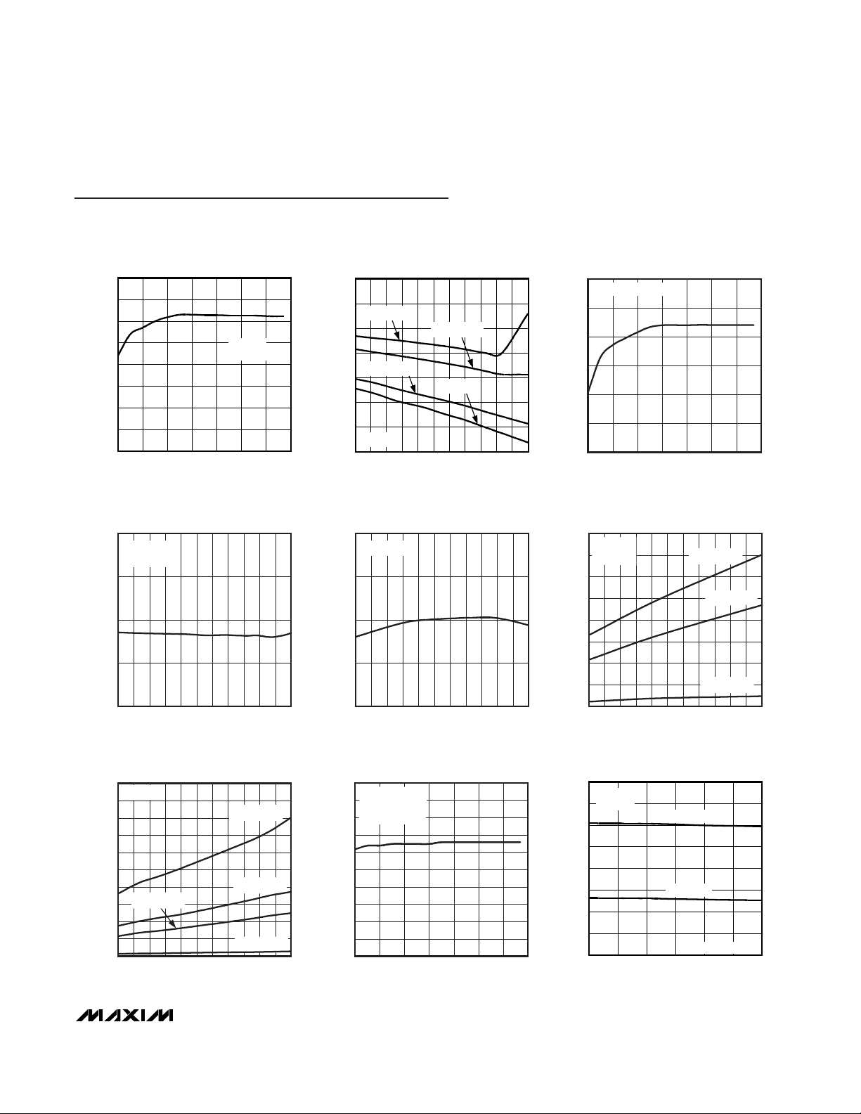
40
50
45
60
55
65
70
75
80
5354515 25 55 65 75
SUPPLY CURRENT
vs. SUPPLY VOLTAGE
MAX6791-96 toc01
SUPPLY VOLTAGE (V)
SUPPLY CURRENT (µA)
MAX6791
NO LOAD
50
60
80
70
90
100
110
120
-40 -10 5 20 35-25 50 65 80 11095 125
SUPPLY CURRENT vs. TEMPERATURE
MAX6791 toc02
TEMPERATURE (°C)
SUPPLY CURRENT (µA)
I
LOAD
= 100mA
I
LOAD
= 50mA
I
LOAD
= 1mA
I
LOAD
= 0
MAX6791
10
20
15
30
25
35
40
5354515 25 55 65 75
SHUTDOWN SUPPLY CURRENT
vs. SUPPLY VOLTAGE
MAX6791-96toc03
SUPPLY VOLTAGE (V)
SUPPLY CURRENT (µA)
MAX6793/MAX6794
20
25
35
30
40
-40 -10 5 20 35-25 50 65 80 11095 125
SHUTDOWN SUPPLY CURRENT
vs. TEMPERATURE
MAX6791toc04
TEMPERATURE (°C)
SHUTDOWN SUPPLY CURRENT (µA)
MAX6795
V
IN
= 14V
0.980
0.990
1.010
1.000
1.020
-40 -10 5 20 35-25 50 65 80 11095 125
NORMALIZED RESET THRESHOLD
vs. TEMPERATURE
MAX6791toc05
TEMPERATURE (°C)
NORMALIZED RESET THRESHOLD
MAX6796
0
400
1200
800
1600
200
1000
600
1400
-40 -10 5 20 35-25 50 65 80 11095 125
DROPOUT VOLTAGE
vs. TEMPERATURE
MAX6791toc06
TEMPERATURE (°C)
DROPOUT VOLTAGE (mV)
MAX6792
V
OUT
= 5V
I
LOAD
= 100mA
I
LOAD
= 150mA
I
LOAD
= 10mA
4.980
4.983
4.981
4.987
4.985
4.989
4.982
4.986
4.984
4.988
4.990
5354515 25 55 65 75
OUTPUT VOLTAGE
vs. INPUT VOLTAGE
MAX6791-96toc08
INPUT VOLTAGE (V)
OUTPUT VOLTAGE (V)
MAX6795
PRESET VOLTAGE,
NO LOAD
OUTPUT VOLTAGE vs. LOAD CURRENT
MAX6791-96 toc09
LOAD CURRENT (mA)
V
OUT
(V)
25020050 100 150
2.5
3.0
3.5
4.0
4.5
5.0
5.5
6.0
2.0
0300
MAX6796
V
IN
= 14V
V
OUT
= 5V
V
OUT
= 3.3V
SET EXTERNALLY
Typical Operating Characteristics
(VIN= VEN= 14V, CIN= 0.1µF, C
OUT
= 10µF, TJ= TA= +25°C, unless otherwise noted.)
DROPOUT VOLTAGE
vs. TEMPERATURE
2000
MAX6796
1800
1600
1400
1200
1000
800
DROPOUT VOLTAGE (mV)
I
= 100mA
LOAD
600
400
200
0
-40 -10 5 20 35-25 50 65 80 11095 125
TEMPERATURE (°C)
I
LOAD
I
LOAD
I
LOAD
= 300mA
= 150mA
= 10mA
MAX6791toc07
Page 8
Typical Operating Characteristics (continued)
(VIN= VEN= 14V, CIN= 0.1µF, C
OUT
= 10µF, TJ= TA= +25°C, unless otherwise noted.)
MAX6791–MAX6796
High-Voltage, Micropower, Single/Dual Linear
Regulators with Supervisory Functions
8 _______________________________________________________________________________________
0.98
1.01
1.03
0.99
1.02
1.00
-40 -10 5 20 35-25 50 65 80 11095 125
NORMALIZED RESET TIMEOUT PERIOD
vs. TEMPERATURE
MAX6791toc10
TEMPERATURE (°C)
NORMALIZED RESET TIMEOUT PERIOD
MAX6796
0.980
0.995
1.020
0.985
1.000
0.990
1.010
1.005
1.015
-40 -10 5 20 35-25 50 65 80 11095 125
NORMALIZED WATCHDOG TIMEOUT PERIOD
vs. TEMPERATURE
MAX6791toc12
TEMPERATURE (°C)
NORMALIZED WATCHDOG TIMEOUT PERIOD
MAX6796
0.995
0.998
1.001
0.996
0.999
0.997
1.000
-40 -10 5 20 35-25 50 65 80 11095 125
NORMALIZED PFI THRESHOLD
vs. TEMPERATURE
MAX6791toc13
TEMPERATURE (°C)
NORMALIZED PFI THRESHOLD
MAX6796
0
1.5
0.5
3.5
2.5
4.5
1.0
3.0
2.0
4.0
5.0
06824 1012 14
RESET OUTPUT
vs. SOURCE CURRENT
MAX6791-96toc14
SOURCE CURRENT (mA)
RESET OUTPUT (V)
MAX6796
RESET OUTPUT VOLTAGE
vs. SINK CURRENT
MAX6791-96toc15
SINK CURRENT (mA)
RESET OUTPUT VOLTAGE (V)
986 72 3 4 51
0.1
0.2
0.3
0.4
0.5
0.6
0.7
0.8
0.9
1.0
0
0
10
MAX6796
-40
PSRR vs. FREQUENCY
VIN = 6V
-45
-50
-55
-60
PSRR (dB)
-65
-70
-75
-80
= 1.8V
V
OUT
= 10mA
I
LOAD
10 100 1k 100k
FREQUENCY (Hz)
MAX6791toc11
10k
Page 9

MAX6791–MAX6796
High-Voltage, Micropower, Single/Dual Linear
Regulators with Supervisory Functions
_______________________________________________________________________________________ 9
Typical Operating Characteristics (continued)
(VIN= VEN= 14V, CIN= 0.1µF, C
OUT
= 10µF, TJ= TA= +25°C, unless otherwise noted.)
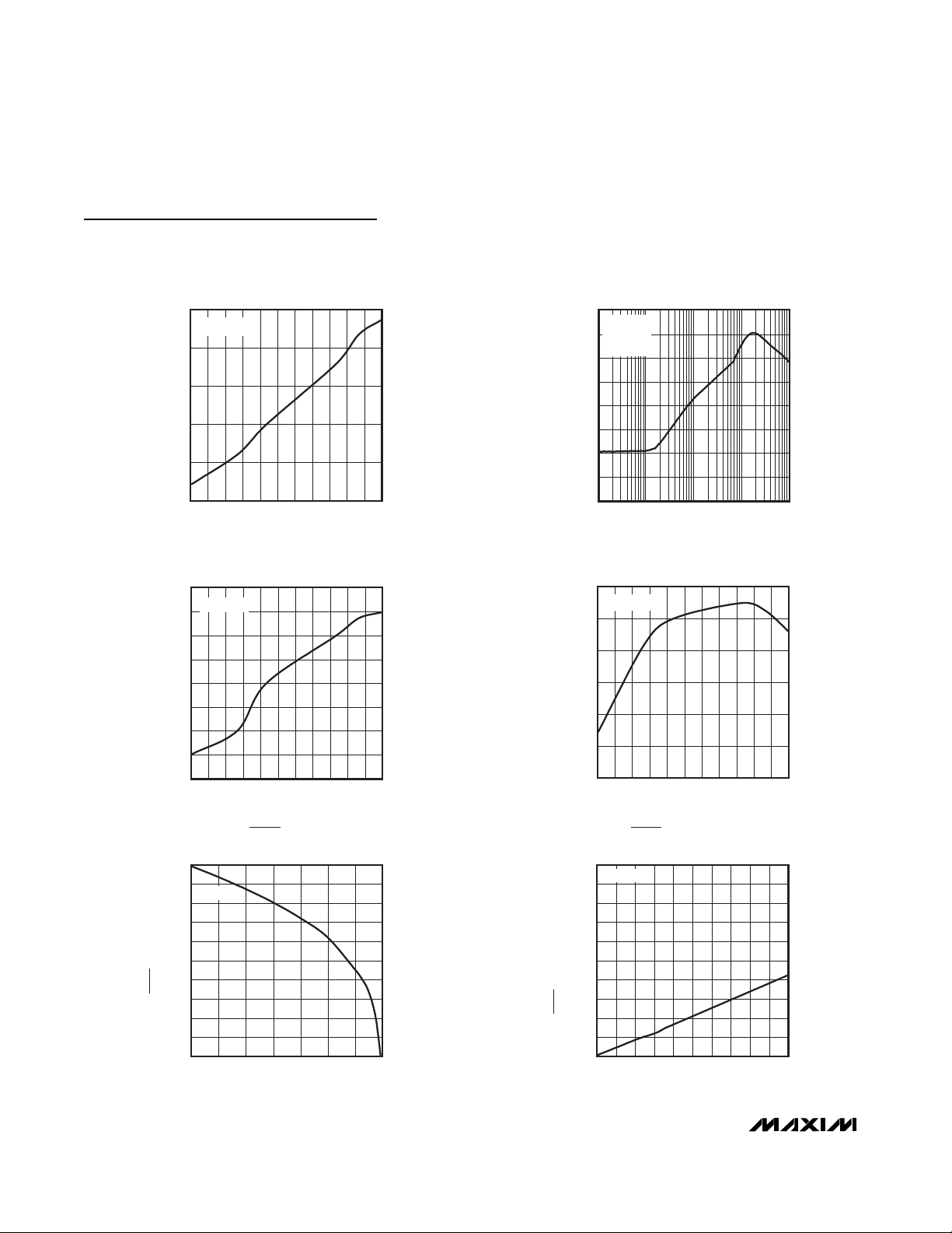
10,000
1000
100
10
1
0.1
0.0001 0.01 0.10.001 1
RESET TIMEOUT PERIOD
vs. C
CSRT
MAX6791-96toc16
C
CSRT
(µF)
RESET TIMEOUT PERIOD (ms)
WATCHDOG TIMEOUT PERIOD
vs. C
CSWT
MAX6791-96toc17
C
CSWT
(µF)
WATCHDOG TIMEOUT PERIOD
0.010.001
10
100
1000
10,000
100,000
1
0.0001 0.1
LOAD-TRANSIENT RESPONSE
MAX6791-96toc18
OUT1
I
OUT1
100mA/div
1mA
1V/div
400µs/div
MAX6796
C
OUT
= 10µF
V
OUT
= 5V
V
IN
= 14V
V
OUT
AC-
COUPLED
LOAD-TRANSIENT RESPONSE
MAX6791-96toc19
I
OUT
OUT
100mA/div
1mA
500mV/div
400µs/div
OUT ACCOUPLED
MAX6796
V
IN
= 14V
V
OUT
= 5V
LINE-TRANSIENT RESPONSE
V
IN
OUT
OUT ACCOUPLED
1ms/div
MAX6791-96toc20
MAX6796
= 10mA
I
LOAD
10V/div
(AC-COUPLED)
20mV/div
Page 10

MAX6791–MAX6796
High-Voltage, Micropower, Single/Dual Linear
Regulators with Supervisory Functions
10 ______________________________________________________________________________________
Pin Description
Typical Operating Characteristics (continued)
(VIN= VEN= 14V, CIN= 0.1µF, C
OUT
= 10µF, TJ= TA= +25°C, unless otherwise noted.)
LOAD-TRANSIENT RESPONSE
MAX6791-96toc21
OUT1
AC-COUPLED
I
OUT1
100mA/div
1mA
500mV/div
1ms/div
MAX6792
OUT1 = 5V
C
OUT
= 10µF
LOAD-TRANSIENT RESPONSE
MAX6791-96toc22
I
OUT1
OUT1
AC-COUPLED
100mA/div
20mA
500mV/div
1ms/div
MAX6792
OUT1 = 5V
C
OUT
= 10µF
PIN
MAX6791/
MAX6792
NAME FUNCTION
1, 2 1, 2 — OUT1
Reg ul ator 1 Outp ut. Fi xed ( + 1.8V , + 2.5V , + 3.3V , or + 5V ) or ad j ustab l e ( + 1.8V to
+ 11V ) . OU T1 = 150m A ( m ax) . C onnect a 10µF ( m i n) cap aci tor fr om OU T1 to GN D .
33—SET1
Feed b ack Inp ut for S etti ng the O U T1 V ol tag e. C onnect S E T1 to GN D to sel ect the
p r eset outp ut vol tag e. C onnect to an exter nal r esi sti ve d i vi d er for ad j ustab l e
outp ut op er ati on.
444PFO
Active-Low, Open-Drain, Power-Fail Comparator Output. PFO asserts low
when PFI is below the internal 1.231V threshold. PFO deasserts when PFI is
above the internal 1.231V threshold.
555CSWT
Watchd og Ti m eout P er i od Ad j ust Inp ut. C onnect C S WT to OU T1/OU T for the
i nter nal l y fi xed w atchd og ti m eout p er i od . For ad j ustab l e w atchd og ti m eout p er i od ,
connect a cap aci tor fr om C S WT to GN D . C onnect C S WT to GN D to d i sab l e the
w atchd og . S ee the S el ecti ng Watchd og Ti m eout P er i od secti on for m or e d etai l s.
666CSRT
Reset Timeout Period Adjust Input. Connect CSRT to OUT1/OUT for the
internally fixed timeout period. For adjustable timeout, connect a capacitor
from CSRT to GND. See the Reset Output section for more details.
777GND Ground
888RESET
Acti ve- Low Reset Outp ut. RES ET r em ai ns l ow w hi l e OU T1/OU T i s b el ow the r eset
thr eshol d . RES ET r em ai ns l ow for the d ur ati on of the r eset ti m eout p er i od after the
r eset cond i ti ons end . RES ET i s avai l ab l e i n p ush- p ul l and op en- d r ai n op ti ons.
MAX6793/
MAX6794
MAX6795/
MAX6796
Page 11

MAX6791–MAX6796
High-Voltage, Micropower, Single/Dual Linear
Regulators with Supervisory Functions
______________________________________________________________________________________ 11
Pin Description (continued)
PIN
MAX6791/
MAX6792
NAME FUNCTION
9——WDS1
10 — — WDS0
Min/Max Watchdog Logic-Select Input. WDS0 and WDS1 select the watchdog
window ratio or disable the watchdog timer. Drive WDS0 and WDS1 high or
low to select the desired ratio, see Table 4.
11 11 11 WDI
Watchdog Input.
M AX 6793–M AX 6796: A fal l i ng or r i si ng tr ansi ti on m ust occur on W D I w i thi n the
sel ected w atchd og ti m eout p er i od or a r eset p ul se occur s. The w atchd og ti m er
cl ear s w hen a tr ansi ti on occur s o n WD I or whenever RESET i s asser ted . C onnect
C S W T to g r ound to d i sab l e the w atchd og ti m er functi on.
MAX6791/MAX6792: W D I fal l i ng and r i si ng tr ansi ti ons w i thi n p er i od s shor ter than
t
WD 1
or l ong er than t
WD 2
force RESET to asser t l ow for the r eset ti m eout p er i od .
The w atchd og ti m er b eg i ns to count after RESET i s d easser ted . The w atchd og
ti m er cl ear s w hen a val i d tr ansi ti on occur s on W D I or w henever RES ET i s
asser ted . C onnect W D S 0 hi g h and WD S 1 l ow to d i sab l e the w atchd og ti m er
functi on. S ee the W atchd og Ti m er secti on.
12 12 12 HOLD
Active-Low Regulator Hold Input. When HOLD is forced low, OUT1/OUT
remains ON even if ENABLE1/ENABLE is pulled low. To shut down the output
of the regulator (OUT/OUT1), release HOLD after ENABLE1/ENABLE is pulled
low. Connect HOLD to OUT1/OUT or leave unconnected if unused. HOLD is
internally connected to OUT/OUT1 through a 2µA current source.
13, 14 13, 14 — OUT2
Regulator 2 Output. OUT2 is a fixed +5V output. Connect a 10µF (min)
capacitor from OUT2 to GND.
15 15 —
Active-High Enable Input 2. Drive ENABLE2 high to turn on OUT2. ENABLE2 is
internally connected to ground through a 0.5µA current sink.
16 16 16 PFI
Adjustable Power-Fail Comparator Input. Connect PFI to a resistive-divider to
set the desired PFI threshold. The PFI input is referenced to an accurate
1.231V threshold.
17, 18 17, 18 17, 18 IN Reg ul ator Inp uts. Byp ass IN w i th a 1µF cap aci tor to G N D .
19 19 19 GATEP
pFET Gate Drive. Connect GATEP to the gate of a p-channel MOSFET to
provide low drop reverse-battery voltage protection.
20 20 —
Active-High Enable Input 1. Drive ENABLE1 high to turn on OUT1. ENABLE1 is
internally connected to ground through a 0.5µA current sink.
—9 9WD-DIS
Watchdog Disable Input. Drive WD-DIS low to disable the watchdog timer.
Drive WD-DIS high or connect to OUT/OUT1 to enable the watchdog timer.
The watchdog timer clears when reset asserts.
MAX6793/
MAX6794
MAX6795/
MAX6796
ENABLE2
ENABLE1
Page 12

MAX6791–MAX6796
High-Voltage, Micropower, Single/Dual Linear
Regulators with Supervisory Functions
12 ______________________________________________________________________________________
Detailed Description
The MAX6791–MAX6796 ultra-low-quiescent-current,
single-/dual-output, high-input-voltage linear regulators
operate from 5V to 72V. The MAX6791–MAX6794 feature dual regulators that deliver up to 150mA of load
current per output. One output is available with preset
output-voltage options (+1.8V, +2.5V, +3.3V, and
+5.0V) and can be adjusted to any voltage between
+1.8V to +11V using an external resistive-divider at
SET1. The other output provides a fixed 5V output voltage. The MAX6795/MAX6796 feature a single regulator
that delivers up to 300mA of current with preset outputvoltage options (+1.8V, +2.5V, +3.3V, and +5.0V) or
can be adjusted to any voltage between +1.8V to +11V.
All devices include an integrated µP reset circuit with a
fixed/adjustable reset and watchdog timeout period.
The MAX6791–MAX6796 monitor OUT/OUT1 and
assert a reset output when the output falls below the
reset threshold.
Regulators
The single and dual regulators accept an input voltage
from 5V to 72V. The MAX6791–MAX6796 offer fixed
preset output voltages of +1.8V, +2.5V, +3.3V, and
+5V, or an adjustable output voltage of +1.8V to +11V,
selected using an external resistive-divider network
connected between OUT1/OUT, SET1/SET, and GND
(see Figure 1). In addition to an adjustable output, the
MAX6791–MAX6794 feature a fixed 5V output voltage.
Reset Output
The reset output is typically connected to the reset
input of a µP. A µP’s reset input starts or restarts the µP
in a known state. The MAX6791–MAX6796 supervisory
circuits provide the reset logic output to prevent codeexecution errors during power-up, power-down, and
brownout conditions (see the Typical Application
Circuit). RESET changes from high to low whenever the
monitored output voltage drops below the reset threshold voltage or the watchdog timeout expires. Once the
monitored voltage exceeds its respective reset threshold voltage, RESET remains low for the reset timeout
period, then goes high.
Pin Description (continued)
PIN
MAX6791/
MAX6792
NAME FUNCTION
—10
10, 13, 14,
15
N.C. Not Internally Connected
——1, 2 OUT
Regulator Output. Fixed +5V, +3.3V, +2.5V, +1.8V, or adjustable output
(+1.8V to +11V). Connect a 10µF (min) capacitor from OUT to GND.
—— 3 SET
Feedback Input for Setting the OUT Voltage. Connect SET to GND to select the
preset output voltage. Connect to an external resistive-divider for adjustable
output operation.
——20 ENABLE
Active-High Enable Input. Drive ENABLE high to turn on the regulator. ENABLE
is internally connected to ground through a 0.5µA current sink.
——— EP
Exposed Pad. EP is internally connected to GND. Connect EP to the ground
plane to provide a low thermal-resistance path from the IC junction to the PC
board. Do not use as the electrical connection to GND.
MAX6793/
MAX6794
MAX6795/
MAX6796
Page 13

MAX6791–MAX6796
High-Voltage, Micropower, Single/Dual Linear
Regulators with Supervisory Functions
______________________________________________________________________________________ 13
Functional Diagrams
MAX6791/MAX6792
THERMAL
PROTECTION
CONTROL
LOGIC
1.23V
124mV
OUT2
OUT1
SET1
RESET
CSRT
WDI
CSWT
WDS0
WDS1
PFO
GND PFI
1.138V
OR
1.076V
OVERCURRENT
PROTECTION
RESET
TIMEOUT
RESET
ENABLE2
IN
GATEP
ENABLE1
HOLD
WATCHDOG
TIMEOUT
Page 14

MAX6791–MAX6796
High-Voltage, Micropower, Single/Dual Linear
Regulators with Supervisory Functions
14 ______________________________________________________________________________________
Functional Diagrams (continued)
MAX6793/MAX6794
THERMAL
PROTECTION
CONTROL
LOGIC
1.23V
124mV
OUT2
OUT1
SET1
RESET
CSRT
WDI
CSWT
WD-DIS
PFO
GND PFI
1.138V
OR
1.076V
OVERCURRENT
PROTECTION
RESET
TIMEOUT
RESET
ENABLE2
IN
GATEP
ENABLE1
HOLD
WATCHDOG
TIMEOUT
Page 15

MAX6791–MAX6796
High-Voltage, Micropower, Single/Dual Linear
Regulators with Supervisory Functions
______________________________________________________________________________________ 15
Functional Diagrams (continued)
MAX6795/MAX6796
THERMAL
PROTECTION
CONTROL
LOGIC
1.23V
124mV
OUT
SET
RESET
CSRT
WDI
CSWT
WD-DIS
PFO
GND PFI
1.138V
OR
1.076V
OVERCURRENT
PROTECTION
RESET
TIMEOUT
RESET
IN
GATEP
ENABLE
HOLD
WATCHDOG
TIMEOUT
Page 16

MAX6791–MAX6796
High-Voltage, Micropower, Single/Dual Linear
Regulators with Supervisory Functions
16 ______________________________________________________________________________________
Watchdog Timer
The MAX6791–MAX6796 include a watchdog timer
that asserts RESET if the watchdog input (WDI) does
not toggle high to low or low to high within the watchdog timeout period tWD(280ms min or externally
adjustable). RESET remains low for the fixed or useradjustable reset timeout period, tRP. If the watchdog is
not updated for lengthy periods of time, the reset output appears as a pulse train, asserted for tRP,
deasserted for tWD, until WDI is toggled again. Once
RESET asserts, it stays low for the entire reset timeout
period ignoring any WDI transitions that may occur. To
prevent the watchdog from asserting RESET, toggle
WDI with a valid rising or falling edge before tWDfrom
the last edge. The watchdog counter clears when WDI
toggles prior to tWDfrom the last edge or when RESET
asserts. The watchdog resumes counting after RESET
deasserts.
The MAX6791/MAX6792 have a windowed watchdog
timer that asserts RESET for the adjusted reset timeout
period when the watchdog recognizes a fast watchdog
fault (t
WDI
< t
WD1
), or a slow watchdog fault (t
WDI
>
t
WD2
). The reset timeout period is adjusted indepen-
dently of the watchdog timeout period.
Enable and Hold Inputs
The MAX6791–MAX6796 support two logic inputs,
ENABLE1/ENABLE and HOLD, making these devices
suitable for automotive applications. For example, when
the ignition key signal drives ENABLE1/ENABLE high,
the regulator turns on and remains on even if
ENABLE1/ENABLE goes low, as long as HOLD is forced
low and stays low after initial regulator power-up. In this
state, releasing HOLD turns the regulator output
(OUT/OUT1) off. This feature makes it possible to implement a self-holding circuit without external components.
Forcing ENABLE1/ENABLE low and HOLD high or
unconnected places the MAX6791–MAX6796 into shutdown mode in which the MAX6791–MAX6796 draw less
than 27µA of supply current.
Table 3 shows the state of the regulator output with
respect to the voltage level at ENABLE1/ENABLE and
HOLD. Connect HOLD to OUT1/OUT or leave it unconnected to allow the ENABLE1/ENABLE input to act as a
standard ON/OFF switch for the regulator output
(OUT/OUT1).
Power-Fail Comparator
PFI is the noninverting input to a comparator. If PFI is
less than V
PFI
(1.231V), PFO goes low. Common uses
for the power-fail comparator include monitoring the
preregulated input of the power supply (such as a battery) or providing an early power-fail warning so software can conduct an orderly system shutdown. Set the
power-fail threshold with a resistive-divider, as shown in
Figure 5. The typical comparator delay is 35µs from PFI
to PFO. Connect PFI to GND or IN if unused.
Reverse-Battery Protection Circuitry
The MAX6791–MAX6796 include an overvoltage protection circuit that is capable of driving a p-channel
MOSFET to protect against reverse-battery conditions.
This MOSFET eliminates the need for external diodes,
thus minimizing the input voltage drop. See the Typical
Application Circuit. The low p-channel MOSFET onresistance of 30mΩ or less yields a forward-voltage
drop of only a few millivolts versus hundreds of millivolts for a diode, thus improving efficiency in batteryoperated devices. Connecting a positive battery
voltage to the drain of Q1 (see the Typical Application
Circuit) forward biases its body diode. When the source
voltage exceeds Q1’s threshold voltage, Q1 turns on.
Once the FET is on, the battery is fully connected to the
system and can deliver power to the device and the
load. An incorrectly inserted battery reverse-biases the
FET’s body diode. The gate remains at the ground
potential. The FET remains off and disconnects the
reversed battery from the system. The internal zener
diode and resistor combination at GATEP prevent damage to the p-channel MOSFET during an overvoltage
condition. See the Functional Diagrams.
Thermal Protection
When the junction temperature exceeds TJ= +165°C,
the internal protection circuit turns off the internal pass
transistor and allows the IC to cool. The thermal sensor
turns the pass transistor on again after the junction temperature drops to +145°C, resulting in a cycled output
during continuous thermal-overload conditions.
Thermal protection protects the MAX6791–MAX6796 in
the event of fault conditions. For continuous operation,
do not exceed the absolute maximum junction temperature rating of +150°C.
Proper Soldering of Package Heatsink
The MAX6791–MAX6796 package features an exposed
thermal pad on its underside that should be used as a
heatsink. This pad lowers the package’s thermal resistance by providing a direct heat-conduction path from
the die to the PC board. Connect the exposed pad and
GND to the system ground using a large pad or ground
plane, or multiple vias to the ground plane layer.
Page 17

MAX6791–MAX6796
High-Voltage, Micropower, Single/Dual Linear
Regulators with Supervisory Functions
______________________________________________________________________________________ 17
Applications Information
Output Voltage Selection
The MAX6791–MAX6796 feature dual-mode operation:
these devices operate in either a preset voltage mode
or an adjustable mode. In preset voltage mode, internal
trimmed feedback resistors set the internal linear regulator to +1.8V, +2.5V, +3.3V, or +5V (see the Selector
Guide). Select preset voltage mode by connecting SET1
(MAX6791–MAX6794)/SET(MAX6795/MAX6796) to
GND. In adjustable mode, select an output voltage
between +1.8V and +11V using two external resistors
connected as a voltage-divider to SET1/SET (see Figure
1). Set the output voltage using the following equation:
where V
SET
= 1.2315V and R1, R2 ≤ 200kΩ.
Available Output-Current Calculation
The MAX6791–MAX6794 provide up to 150mA per output, and the MAX6795/MAX6796 provide up to 300mA
of load current. Since the input voltage can be as high
as +72V, package power dissipation limits the amount
of output current available for a given input/output voltage and ambient temperature. Figure 2 shows the maximum power-dissipation curve for the MAX6791–
MAX6796. The graph assumes that the exposed metal
pad of the device package is soldered to a solid 1in
2
section of PC board copper. Use Figure 2 to determine
the allowable package dissipation for a given ambient
temperature. Alternately, use the following formula to
calculate the allowable package dissipation:
PD
MAX
= Maximum Power Dissipation
PD
MAX
= 2.666W, for TA≤ +70°C
PD
MAX
= [2.666W - 0.0333W x (TA- 70°C)], for +70°C
< T
A
≤ +125°C
where 0.0333W is the MAX6791–MAX6796 package
thermal derating in W/°C and TAis the ambient temperature in °C.
After determining the allowable package dissipation,
calculate the maximum output current using the following formula:
PD = Power Dissipation
PD < PD
MAX
where PD = [(IN - OUT1) x I
OUT1
] + [(IN -
OUT2) x I
OUT2
], for MAX6791–MAX6794.
Also, I
OUT1
should be ≤ 150mA and I
OUT2
should be
≤ 150mA in any case.
PD < PD
MAX
where PD = [(IN - OUT) x I
OUT
], for
MAX6795/MAX6796.
Also, I
OUT
should be ≤ 300mA in any case.
Selecting Reset Timeout Period
The reset timeout period is adjustable to accommodate
a variety of µP applications. Adjust the reset timeout
period by connecting a capacitor between CSRT and
GND. Use the following formula to set the reset timeout
period:
where tRPis in seconds and C
CSRT
is in Farads.
Connect CSRT to OUT1 (MAX6791–MAX6794) or to
OUT (MAX6795/MAX6796) to select an internally fixed
timeout period. Connect CSRT to GND to force RESET
low. C
CSRT
must be a low-leakage (< 10nA) type
capacitor. Ceramic capacitors are recommended; do
not use capacitors lower than 100pF to avoid the influence of parasitic capacitances.
tC
V
A
RP CSRT
. =×
1 218 10
6
VV
R
R
OUT SET
=+
1
1
2
MAX6791–MAX6796
V
IN
R1
R2
OUT1/OUT
SET1/SET
IN
GND
Figure 1. Setting the Output Voltage Using a Resistive-Divider
I
OUT
vs. (VIN - V
OUT
)
(VIN - V
OUT
) (V)
I
OUT
(mA)
70 75605040302010
50
100
150
200
250
300
350
0
0
+70°C
+85°C
+125°C
V
OUT
= 1.8V
SAFE OPERATION REGION FOR
EACH TEMPERATURE POINT IS
UNDER THE CURVE
Figure 2. Maximum Power Dissipation for MAX6791–MAX6796
Page 18

MAX6791–MAX6796
High-Voltage, Micropower, Single/Dual Linear
Regulators with Supervisory Functions
18 ______________________________________________________________________________________
Selecting Watchdog Timeout Period
The watchdog timeout period is adjustable to accommodate a variety of µP applications. With this feature, the
watchdog timeout can be optimized for software execution. The programmer can determine how often the
watchdog timer should be serviced. Adjust the watchdog timeout period (tWD) by connecting a capacitor
between CSWT and GND. For normal-mode operation,
calculate the watchdog timeout capacitor as follows:
where tWDis in seconds and C
CSWT
is in Farads.
To select the internally fixed watchdog timeout period
for the MAX6791–MAX6794, connect CSWT to OUT1.
To select the internally fixed watchdog timeout period
for the MAX6795/MAX6796, connect CSWT to OUT.
Driving CSWT low disables the watchdog timer.
C
CSWT
must be a low-leakage (< 10nA) type capacitor.
Ceramic capacitors are recommended; do not use
capacitors lower than 100pF to avoid the influence of
parasitic capacitances.
The MAX6791/MAX6792 have a windowed watchdog
timer that asserts RESET for t
RP
when the watchdog
recognizes a fast watchdog fault (time between transitions < t
WD1
), or a slow watchdog fault (time between
transitions > t
WD2
). The reset timeout period is adjusted independently of the watchdog timeout period. The
slow watchdog period, t
WD2
, is calculated as follows:
where t
WD2
is in seconds and C
CSWT
is in Farads.
The fast watchdog period, t
WD1
, is selectable as a ratio
from the slow watchdog fault period (t
WD2
). Select the
fast watchdog period by connecting WDS0 and WDS1 to
OUT/OUT1 or GND according to Table 4, which illustrates the settings for the 8, 16, and 64 window ratios
(t
WD2/tWD1
). For example, if C
CSWT
is 2000pF, and
WDS0 and WDS1 are low, then t
WD2
is 318ms (typ) and
t
WD1
is 40ms (typ). RESET asserts if the watchdog input
has two edges too close to each other (faster than t
WD1
);
or has edges that are too far apart (slower than t
WD2
).
All WDI inputs are ignored while RESET is asserted. The
watchdog timer begins to count after RESET is
deasserted. If the time difference between two transitions on WDI is shorter than t
WD1
or longer than t
WD2
,
RESET is forced to assert low for the reset timeout period. If the time difference between two transitions on WDI
is between t
WD1
(min) and t
WD1
(max) or t
WD2
(min)
and t
WD2
(max), RESET is not guaranteed to assert or
deassert; see Figure 3. To guarantee that the window
watchdog does not assert RESET, strobe WDI between
t
WD1
(max) and t
WD2
(min). The watchdog timer is
cleared when RESET is asserted. Disable the watchdog
timer by connecting WDS0 high and WDS1 low.
There are several options available to disable the
watchdog timer (for system development or test purposes or when the µP is in a low-power sleep mode).
One way to disable the watchdog timer is to drive
WD-DIS low for the MAX6793–MAX6796 and drive
WDS0 high and WDS1 low for the MAX6791/MAX6792.
Another method of disabling the watchdog timer is to
pull CSWT low with an open-drain driver stage. This
prevents the capacitor from ramping up. Finally, reducing the OUT/OUT1 regulator current below the specified regulator current watchdog-disable threshold (3mA
min) also disables the watchdog timer. The watchdog
tC
V
WD CSWT2
6
155 10 =×
tC
V
A
WD CSWT2
6
155 10 =×
t
WD1
t
WD2
t
WD0
MIN
GUARANTEED
TO ASSERT
UNDETERMINED UNDETERMINED
GUARANTEED
TO NOT ASSERT
GUARANTEED
TO ASSERT
FAST
FAULT
NORMAL
OPERATION
SLOW
FAULT
RESET:
WDI INPUT:
MAX MIN MAX
Figure 3. Windowed Watchdog Timing Diagram
Page 19

MAX6791–MAX6796
High-Voltage, Micropower, Single/Dual Linear
Regulators with Supervisory Functions
______________________________________________________________________________________ 19
reenables immediately when any of these conditions
are removed (as long as the RESET is not asserted).
Note that the output current threshold limit includes
hysteresis so that output current must exceed 13.8mA
(max) to reenable the watchdog timer.
Capacitor Selection and Regulator
Stability
For stable operation over the full temperature range
and with load currents up to 150mA, use a 10µF (min)
output capacitor with an ESR < 0.5Ω. To reduce noise
and improve load-transient response and power-supply
rejection, use larger output-capacitor values. Some
ceramic dielectrics exhibit large capacitance and ESR
variation with temperature. For these types of capacitors (such as Z5U and Y5V), much higher-value capacitors are required to maintain stability over the
temperaure range. With X7R dielectrics, a 10µF capacitor should be sufficient at all operating temperatures.
To improve power-supply rejection and transient
response, increase the capacitor between IN and GND.
Ensuring a Valid
RESET
Output Down to
V
IN
= 0
When V
IN
falls below 1V, RESET current-sinking capa-
bilities decline drastically. High-impedance CMOSlogic inputs connected to RESET can drift to
undetermined voltages. This presents no problems in
most applications, since most µPs and other circuitry
do not operate with a supply voltage below 1V. In those
applications where RESET must be valid down to 0,
adding a pulldown resistor between RESET and GND
sinks any stray leakage currents, holding RESET low
(Figure 4). The value of the pulldown resistor is not critical; 100kΩ is large enough not to load RESET and
small enough to pull RESET to ground. Open-drain
RESET versions are not recommended for applications
requiring valid logic for V
IN
down to 0.
Adding Hysteresis to PFI
The power-fail comparator has a typical input hysteresis of 0.5% (of VTH). This is sufficient for most applications where a power-supply line is being monitored
through an external resistive-divider (Figure 5). Figure 6
shows how to add hysteresis to the power-fail comparator. Select the ratio of R5 and R6 so PFI sees 1.23V
when VINfalls to the desired trip point (V
TRIP
). Since
PFO is an open-drain output, resistors R7 and R8 add
hysteresis. R7 typically is an order of magnitude
greater than R5 or R6. The current through R5 and R6
should be at least 10µA to ensure that the 100nA (max)
PFI input current does not shift the trip point. R7 should
be larger than 50kΩ to prevent it from loading down the
PFO.
MAX6792
MAX6794
MAX6796
V
IN
RESET
IN
GND
Figure 4. Ensuring
RESET
Valid to VIN= 0V
MAX6791
V
IN
V
TERM
R5
R6
PFOPFI
IN
GND
Figure 5. Setting Power-Fail Comparator to Monitor V
IN
MAX6791
V
IN
V
TERM
R5
R7
R8
R6
PFOPFI
IN
GND
Figure 6. Adding Hysteresis Power-Fail Comparator
Page 20

MAX6791–MAX6796
High-Voltage, Micropower, Single/Dual Linear
Regulators with Supervisory Functions
20 ______________________________________________________________________________________
Use the following formulas to determine the high/low
threshold levels and the hysteresis:
V
L-H
= V
PFI
x (1 + R5 / R6 +R5 / R7)
V
H-L
= V
PFI
x (1 + R5 / R6 ) + (V
PFI
- V
TERM
) [R5 / (R7 +
R8)]
V
HYS
= V
PFI
x (R5 / R7 ) - (V
PFI
- V
TERM
) [R5 / (R7 +
R8)]
where V
L-H
is the threshold level for the monitored volt-
age rising and V
H-L
is the threshold level for the moni-
tored voltage falling.
Chip Information
PROCESS: BiCMOS
Table 2. Preset Timeout Period
PART
SUFFIX (_)
RESET TIMEOUT PERIOD
(NOMINAL)
D0 35µs
D1 3.125ms
D2 12.5ms
D3 50ms
D4 200ms
Table 1. Preset Output Voltage and Reset
Threshold
PART
SUFFIX (_)
OUTPUT
RESET THRESHOLD
(NOMINAL)
L 5.0 4.625
M 5.0 4.375
T 3.3 3.053
S 3.3 2.888
Z 2.5 2.313
Y 2.5 2.188
W 1.8 1.665
V 1.8 1.575
Table 3. ENABLE/ENABLE1 and HOLD Truth Table/State Table
VOLTAGE (V)
OPERATING
STATE
Initial state Low Don’t care Off
Turn-on state High Don’t care On
Hold setup state High Low On
Hold state Low Low On
Off state Low
ENABLE1/
ENABLE
HOLD
High (floats
high)
REGULATOR 1
OUTPUT
Off
COMMENT
ENABLE/ENABLE1 is pulled to GND through internal pulldown.
OUT/OUT1 is disabled.
ENABLE/ENABLE1 is externally driven high turning OUT/OUT1
on. HOLD is pulled up to OUT/OUT1.
HOLD is externally pulled low while ENABLE/ENABLE1
remains high, and the regulator latches on.
ENABLE/ENABLE1 is driven low (or allowed to float low by an
internal pulldown). HOLD remains externally pulled low
keeping OUT/OUT1 on.
HOLD i s d r i ven hi g h ( or al l ow ed to fl oat hi g h b y the i nter nal p ul l up )
w hi l e E N ABLE /E N ABLE 1 i s l ow . OUT/OUT1 i s tur ned off and
E N ABLE /E N ABLE 1 and HOLD l og i c r etur ns to the i ni ti al state.
Page 21

MAX6791–MAX6796
High-Voltage, Micropower, Single/Dual Linear
Regulators with Supervisory Functions
______________________________________________________________________________________ 21
Table 4. MIN/MAX Watchdog Setting
WDS0 WDS1 RATIO
00 8
01 16
10Watchdog disabled
11 64
Table 5. Standard Version Part Number
PART
RESET OUTPUT
NUMBER OF
OUTPUTS
WINDOWED
ENABLE
INPUTS
WATCHDOG
DISABLE INPUT
MAX6791TP_D_ Open drain 2 ✓ Dual ✓
MAX6792TP_D_ Push-pull 2 ✓ Dual ✓
MAX6793TP_D_ Open drain 2 — Dual ✓
MAX6794TP_D_ Push-pull 2 — Dual ✓
MAX6795TP_D_ Open drain 1 — Single ✓
MAX6796TP_D_ Push-pull 1 — Single ✓
+Denotes lead-free package.
Selector Guide
PART NUMBER
MAX6791TPLD2+ 5.0 12.5 4.625
MAX6791TPSD2+ 3.3 12.5 2.888
MAX6792TPLD2+ 5.0 12.5 4.625
MAX6792TPSD2+ 3.3 12.5 2.888
MAX6793TPLD2+ 5.0 12.5 4.625
MAX6793TPSD2+ 3.3 12.5 2.888
MAX6794TPLD2+ 5.0 12.5 4.625
MAX6794TPSD2+ 3.3 12.5 2.888
MAX6795TPLD2+ 5.0 12.5 4.625
MAX6795TPSD2+ 3.3 12.5 2.888
MAX6796TPLD2+ 5.0 12.5 4.625
MAX6796TPSD2+ 3.3 12.5 2.888
OUTPUT
VOLTAGE (V)
RESET TIMEOUT PERIOD (ms)
(NOMINAL)
RESET THRESHOLD (V)
(NOMINAL)
WATCHDOG TIMEOUT
Page 22

MAX6791–MAX6796
High-Voltage, Micropower, Single/Dual Linear
Regulators with Supervisory Functions
22 ______________________________________________________________________________________
Typical Application Circuit
MAX6791/MAX6792
IN
I/O
µC
RESET I/O
ENABLE1
12V
BATT
PFI
ENABLE2
TO OTHER CIRCUITRY
OUT2
WDI
OUT1
SET1
INT
V
CC
CSWT
PFO
INGATEP
HOLD WDS1 WDS0
XCVR
TXD
V
CC
INH BATT
RXD
CANH
CANL
RESETGNDCSRT
Page 23

MAX6791–MAX6796
High-Voltage, Micropower, Single/Dual Linear
Regulators with Supervisory Functions
______________________________________________________________________________________ 23
MAX6791/MAX6792
THIN QFN
5mm x 5mm
TOP VIEW
19
20
18
17
7
6
8
OUT1
PFO
CSWT
9
OUT1
OUT2
HOLD
WDI
ENABLE2
1+2
IN
45
15 14 12 11
GATEP
ENABLE1
WDS1
RESET
GND
CSRT
SET1
OUT2
3
13
IN
16
10
WDS0
PFI
TOP VIEW
TOP VIEW
MAX6793/MAX6794
THIN QFN
5mm x 5mm
19
20
18
17
7
6
8
OUT1
PFO
CSWT
9
OUT1
OUT2
HOLD
WDI
ENABLE2
1+2
IN
45
15 14 12 11
GATEP
ENABLE1
WD-DIS
RESET
GND
CSRT
SET1
OUT2
3
13
IN
16
10
N.C.
PFI
MAX6795/MAX6796
THIN QFN
5mm x 5mm
19
20
18
17
7
6
8
OUT
PFO
CSWT
9
OUT
N.C.
HOLD
WDI
N.C.
1+2
IN
45
15 14 12 11
GATEP
ENABLE
WD-DIS
RESET
GND
CSRT
SET
N.C.
3
13
IN
16
10
N.C.
PFI
Pin Configurations
Page 24

MAX6791–MAX6796
High-Voltage, Micropower, Single/Dual Linear
Regulators with Supervisory Functions
24 ______________________________________________________________________________________
QFN THIN.EPS
D2
(ND-1) X e
e
D
C
PIN # 1
I.D.
(NE-1) X e
E/2
E
0.08 C
0.10 C
A
A1
A3
DETAIL A
E2/2
E2
0.10 M C A B
PIN # 1 I.D.
b
0.35x45°
D/2
D2/2
L
C
L
C
e e
L
CC
L
k
L
L
DETAIL B
L
L1
e
AAAAA
MARKING
I
1
2
21-0140
PACKAGE OUTLINE,
16, 20, 28, 32, 40L THIN QFN, 5x5x0.8mm
-DRAWING NOT TO SCALE-
L
e/2
Package Information
(The package drawing(s) in this data sheet may not reflect the most current specifications. For the latest package outline information
go to www.maxim-ic.com/packages
.)
Page 25

MAX6791–MAX6796
High-Voltage, Micropower, Single/Dual Linear
Regulators with Supervisory Functions
Maxim cannot assume responsibility for use of any circuitry other than circuitry entirely embodied in a Maxim product. No circuit patent licenses are
implied. Maxim reserves the right to change the circuitry and specifications without notice at any time.
Maxim Integrated Products, 120 San Gabriel Drive, Sunnyvale, CA 94086 408-737-7600 ____________________ 25
© 2005 Maxim Integrated Products Printed USA is a registered trademark of Maxim Integrated Products, Inc.
COMMON DIMENSIONS
MAX.
EXPOSED PAD VARIATIONS
D2
NOM.MIN.
MIN.
E2
NOM. MAX.
NE
ND
PKG.
CODES
1. DIMENSIONING & TOLERANCING CONFORM TO ASME Y14.5M-1994.
2. ALL DIMENSIONS ARE IN MILLIMETERS. ANGLES ARE IN DEGREES.
3. N IS THE TOTAL NUMBER OF TERMINALS.
4. THE TERMINAL #1 IDENTIFIER AND TERMINAL NUMBERING CONVENTION SHALL
CONFORM TO JESD 95-1 SPP-012. DETAILS OF TERMINAL #1 IDENTIFIER ARE
OPTIONAL, BUT MUST BE LOCATED WITHIN THE ZONE INDICATED. THE TERMINAL #1
IDENTIFIER MAY BE EITHER A MOLD OR MARKED FEATURE.
5. DIMENSION b APPLIES TO METALLIZED TERMINAL AND IS MEASURED BETWEEN
0.25 mm AND 0.30 mm FROM TERMINAL TIP.
6. ND AND NE REFER TO THE NUMBER OF TERMINALS ON EACH D AND E SIDE RESPECTIVELY.
7. DEPOPULATION IS POSSIBLE IN A SYMMETRICAL FASHION.
8. COPLANARITY APPLIES TO THE EXPOSED HEAT SINK SLUG AS WELL AS THE TERMINALS.
9. DRAWING CONFORMS TO JEDEC MO220, EXCEPT EXPOSED PAD DIMENSION FOR
T2855-3 AND T2855-6.
NOTES:
SYMBOL
PKG.
N
L1
e
E
D
b
A3
A
A1
k
10. WARPAGE SHALL NOT EXCEED 0.10 mm.
JEDEC
0.70 0.800.75
4.90
4.90
0.25
0.250--
4
WHHB
4
16
0.350.30
5.10
5.105.00
0.80 BSC.
5.00
0.05
0.20 REF.
0.02
MIN. MAX.NOM.
16L 5x5
L
0.30 0.500.40
---
---
WHHC
20
5
5
5.00
5.00
0.30
0.55
0.65 BSC.
0.45
0.25
4.90
4.90
0.25
0.65
--
5.10
5.10
0.35
20L 5x5
0.20 REF.
0.75
0.02
NOM.
0
0.70
MIN.
0.05
0.80
MAX.
---
WHHD-1
28
7
7
5.00
5.00
0.25
0.55
0.50 BSC.
0.45
0.25
4.90
4.90
0.20
0.65
--
5.10
5.10
0.30
28L 5x5
0.20 REF.
0.75
0.02
NOM.
0
0.70
MIN.
0.05
0.80
MAX.
---
WHHD-2
32
8
8
5.00
5.00
0.40
0.50 BSC.
0.30
0.25
4.90
4.90
0.50
--
5.10
5.10
32L 5x5
0.20 REF.
0.75
0.02
NOM.
0
0.70
MIN.
0.05
0.80
MAX.
0.20 0.25 0.30
DOWN
BONDS
ALLOWED
YES3.103.00 3.203.103.00 3.20T2055-3
3.103.00 3.203.103.00 3.20
T2055-4
T2855-3 3.15 3.25 3.35 3.15 3.25 3.35
T2855-6
3.15 3.25 3.35 3.15 3.25 3.35
T2855-4 2.60 2.70 2.80 2.60 2.70 2.80
T2855-5 2.60 2.70 2.80 2.60 2.70 2.80
T2855-7 2.60 2.70
2.80
2.60 2.70 2.80
3.20
3.00 3.10T3255-3 3 .203.00 3.10
3.203.00 3.10T3255-4 3 .203.00 3.10
NO
NO
NO
NO
YES
YES
YES
YES
3.203.00T1655-3 3.10 3.00 3.10 3.20 NO
NO3.203.103.003.10T1655N-1 3.00 3.20
3.353.15T2055-5 3.25 3.15 3.25 3.35
YES
3.35
3.15
T2855N-1
3.25 3.15 3.25 3.35
NO
3.353.15T2855-8 3.25 3.15 3.25 3.35
YES
3.203.10T3255N-1 3.00
NO
3.203.103.00
L
0.40
0.40
**
**
**
**
**
**
**
**
**
**
**
**
**
**
SEE COMMON DIMENSIONS TABLE
±0.15
11. MARKING IS FOR PACKAGE ORIENTATION REFERENCE ONLY.
I
2
2
21-0140
PACKAGE OUTLINE,
16, 20, 28, 32, 40L THIN QFN, 5x5x0.8mm
-DRAWING NOT TO SCALE-
12. NUMBER OF LEADS SHOWN ARE FOR REFERENCE ONLY.
3.30T4055-1 3.20 3.40 3.20 3.30 3.40
**
YES
0.050 0.02
0.600.40 0.50
10
-----
0.30
40
10
0.40 0.50
5.10
4.90 5.00
0.25 0.35 0.45
0.40 BSC.
0.15
4.90
0.250.20
5.00 5.10
0.20 REF.
0.70
MIN.
0.75 0.80
NOM.
40L 5x5
MAX.
13. LEAD CENTERLINES TO BE AT TRUE POSITION AS DEFINED BY BASIC DIMENSION "e", ±0.05.
T1655-2
**
YES3.203.103.003.103.00 3.20
T3255-5 YES3.003.103.00
3.20
3.203.10
**
exceptions
Package Information (continued)
(The package drawing(s) in this data sheet may not reflect the most current specifications. For the latest package outline information
go to www.maxim-ic.com/packages
.)
 Loading...