

Page 1
General Description
The MAX6684 is an integrated fan-failure detector that
detects when a fan exhibits excessive underspeed or a
locked rotor. This device is especially well suited for critical systems where no fan control, or simple on/off control
is desired. The MAX6684 detects fan failure by evaluating fluctuations in current at the low side of the fan; no
tachometer signal is necessary. The output of the device,
FAIL, is an active-low, open-drain alarm. The MAX6684
can also be used to switch the fan on or off, based on
the state of a logic-level input, OFF. This device can be
used with fans rated at up to 24V and 250mA. The
MAX6684 is available in an 8-pin SO package, and is
specified for operation from -40°C to +85°C.
Applications
Desktop PCs
Notebooks
Networking Equipment
Telecommunications
Industrial Applications
Features
♦ Dedicated Fan-Failure Detector
♦ Works with Ordinary 2-Wire Fans
♦ No Fan Tachometer Output Required
♦ No Software Development Required
♦ No Analog Circuit Design Required
♦ Logic-Level Fan Driver Control
♦ Works with Fans Rated Up to 24V/250mA
MAX6684
Fan-Failure Detector with Integrated
Power Switch
________________________________________________________________ Maxim Integrated Products 1
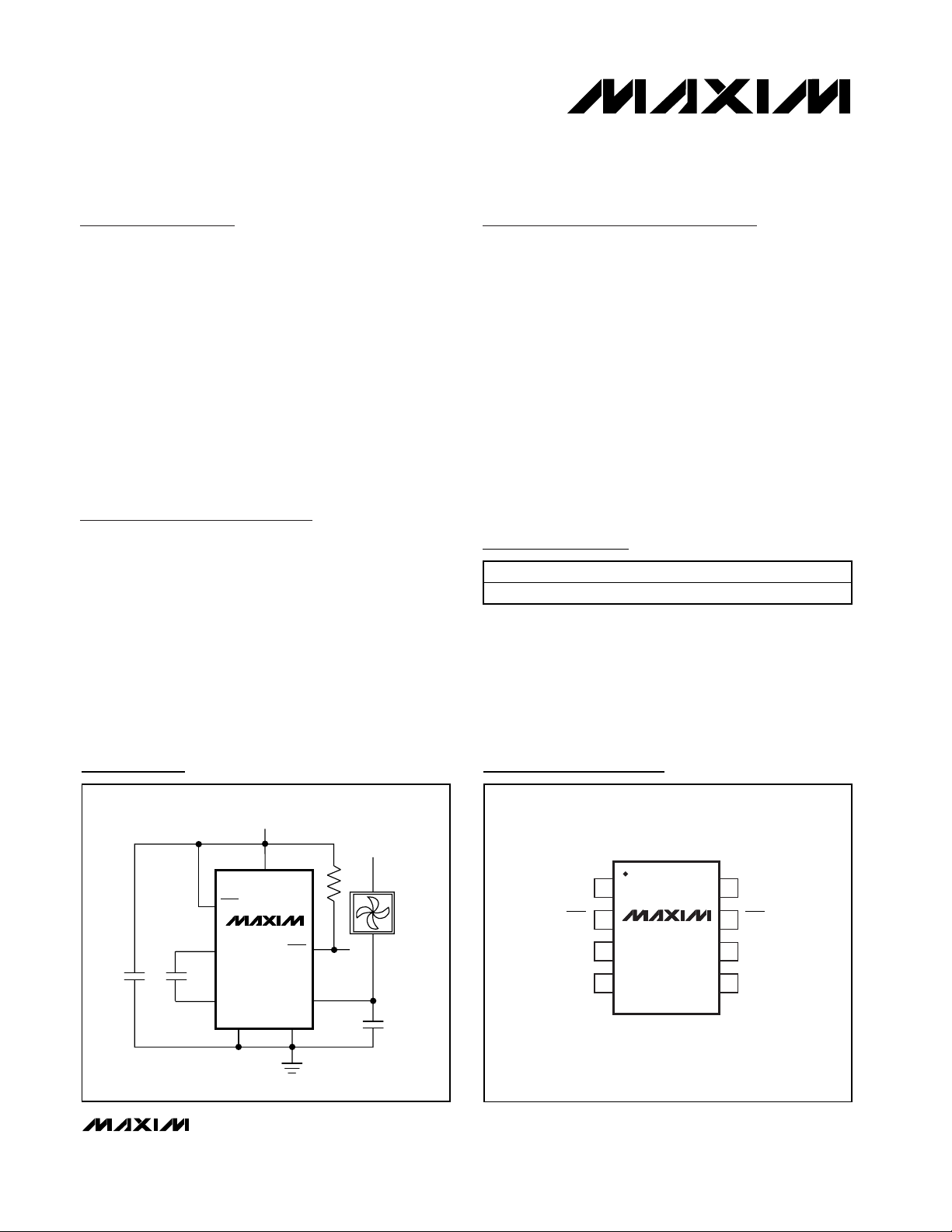
Pin Configuration
Ordering Information
MAX6684
OFF
SENSE
V
CC
12V
PGND
GND
FC+
10kΩ
FC-
3.3V
1µF
0.1µF
0.1µF
FAIL
Typical Operating Circuit
19-2306; Rev 0; 1/02
For pricing, delivery, and ordering information, please contact Maxim/Dallas Direct! at
1-888-629-4642, or visit Maxim’s website at www.maxim-ic.com.
PART TEMP RANGE PIN-PACKAGE
MAX6684ESA -40°C to +85°C 8 SO
TOP VIEW
SENSE
1
2
87PGND
OFFFAIL
MAX6684
GND
3
4
SO
V
6
5
FC+FC-
CC
Page 2
MAX6684
Fan-Failure Detector with Integrated
Power Switch
2 _______________________________________________________________________________________
ABSOLUTE MAXIMUM RATINGS
ELECTRICAL CHARACTERISTICS
(VCC= 3.0 to 5.5V, OFF = VCC, TA= -40°C to +85°C, unless otherwise noted. Typical values are at VCC= 3.3V, TA= +25°C.) (Note 1)
Stresses beyond those listed under “Absolute Maximum Ratings” may cause permanent damage to the device. These are stress ratings only, and functional
operation of the device at these or any other conditions beyond those indicated in the operational sections of the specifications is not implied. Exposure to
absolute maximum rating conditions for extended periods may affect device reliability.
Note 1: Specifications to -40°C are guaranteed by design and not production tested.
Note 2: The MAX6684 is guaranteed to register a fault when the fan current fluctuates less than the minimum; it is guaranteed not to
register a fault when the fan current is above the maximum.
Voltages Referenced to GND, Unless Otherwise Noted
V
CC
........................................................................-0.3V to +6.0V
FC+, FC-.....................................................-0.3V to (VCC+ 0.3V)
OFF, FAIL ..............................................................-0.3V to +6.0V
PGND ....................................................................-0.3V to +0.3V
SENSE to PGND ..................................................-0.3V to +28.0V
SENSE Current................................................................1400mA
Continuous Power Dissipation (TA= +70°C)
8-Pin SO (derate 5.9mW/°C above +70°C)..................470mW
Operating Temperature Range ...........................-40°C to +85°C
Storage Temperature Range .............................-65°C to +150°C
Junction Temperature......................................................+150°C
Soldering Temperature (vapor phase, 60s).....................+215°C
Soldering Temperature (infrared, 15s).............................+220°C
Supply Voltage V
Supply Current I
V
CC
SENSE-to-PGND Output
Low Voltage
SENSE-to-PGND Output
On-Resistance
SENSE Leakage Current V
V
FAIL
V
FAIL
Average SENSE (Fan) Current 50 300
SENSE Current Shutdown VCC = 3V 600 1200 mA
Thermal Shutdown of SENSE 15°C hysteresis 160 °C
Fan-Current Fluctuation
Frequency
V
FAIL
Minimum Fan-Current Fluctuation
Level (Note 2)
OFF Input High Voltage V
OFF Input Low Voltage V
OFF Input Current -10 0 1 µA
PARAMETER SYMBOL CONDITIONS MIN TYP MAX UNITS
CC
CC
Shutdown Supply Current I
Output Low Voltage I
Output Leakage Current V
Output Delay After Fault t
SHDN
R
DSON
FD
IH
IL
I
= 300mA 3.4 mA
FAN
OFF = GND 10 µA
= 300mA 0.3 0.66 V
I
FAN
= 26V 1 10 µA
SENSE
= 3mA 0.8 V
FAIL
= 5.5V 0.1 1 µA
FAIL
No fault detected 25 400 Hz
No fault detected 15 35 60 mA
3.0 5.5 V
1 2.2 Ω
0.3 1 2.0 s
0.7 x
V
CC
0.3 x
V
CC
mA
P-P
V
V
Page 3
MAX6684
Fan-Failure Detector with Integrated
Power Switch
_______________________________________________________________________________________ 3
Typical Operating Characteristics
(VCC= 3.3V, TA= +25°C, unless otherwise noted.)
Pin Description
R
vs. TEMPERATURE
DSON
VCC = 3V
VCC = 5.5V
I
= 300mA
SENSE
-40 85
TEMPERATURE (°C)
603510-15
MAX6684 toc01
(Ω)
DSON
R
2.0
1.6
1.2
0.8
0.4
0
SUPPLY CURRENT vs. TEMPERATURE
300
275
250
SUPPLY CURRENT (µA)
225
200
-40 85
VCC = 5.5V
VCC = 3V
TEMPERATURE (°C)
NO LOAD
603510-15
MAX6684 toc02
500mA/div
V
I
V
FAIL
5V/div
SENSE
2V/div
SENSE
OVERCURRENT OPERATION
MAX6684 toc03
0A
0
0
20ms/div
PIN NAME FUNCTION
1 SENSE Positive Current-Sensing Terminal. Connect SENSE to low side of fan.
2 FAIL Active-Low, Open-Drain Fan-Failure Output
3 GND Ground
4 FC-
5 FC+
Connect to 0.1µF capacitor for most locked-rotor detection applications. To detect minimum speed,
select C
according to Minimum Speed and Locked-Rotor Detection.
F
Connect to 0.1µF capacitor for most locked-rotor detection applications. To detect minimum speed,
select C
according to Minimum Speed and Locked-Rotor Detection.
F
6VCCSupply Voltage Input. Bypass VCC to GND with a 1µF capacitor.
7 OFF Acti ve- Low Fan- C ontr ol Inp ut. D r i ve O FF hi g h or l eave fl oati ng to tur n fan on. D r i ve O FF l ow to tur n fan off.
8 PGND Power Ground. Connect to GND.
Page 4

MAX6684
Detailed Description
The MAX6684 detects fan failure in brushless DC fans.
This device is especially well suited for critical systems
where no fan control is desired. No software is necessary to control the MAX6684.
Fan-Failure Detection
Fan failure is determined based on the fan current
observed at SENSE. The current observed at SENSE is
converted to a voltage, V
FAN
, and highpass filtered by
the capacitor, CF, from FC+ to FC- (Figure 1).
Fan-Failure Detector with Integrated
Power Switch
4 _______________________________________________________________________________________
Figure 1. MAX6684 Functional Diagram
Figure 2. MAX6684 State Diagram
V
CC
MAX6684
SENSE
OFF
CURRENT-SENSE AND
CURRENT-LIMITING
CIRCUIT
V
FAN
OSCILLATOR
8.2kHz 8Hz
FAULT-
DETECTION
DELAY
FAIL
FC+
C
F
FC-
70mV
UNDERCURRENT*
COMP
GND PGND
UNDERCURRENT*
1s DELAY
NORMAL
CURRENT
FAN ON,
FAIL LOW
NORMAL
CURRENT
NORMAL
CURRENT
OVERCURRENT
2ms DELAY
NOISE
BLANK
NORMAL
FAN OPERATION
FAN ON,
FAIL HIGH
THERMAL
SHUTDOWN
OVERCURRENT
THERMAL SHUTDOWN
R
SQ
LATCH
60ms DELAY
NO THERMAL
SHUTDOWN
OVERCURRENT
FAN OFF,
FAIL LOW
THERMAL SHUTDOWN
OVERCURRENT
*INVALID COMMUTATION CURRENT
NOTE: A THERMAL SHUTDOWN CONDITION OVERIDES ALL OTHER CONDITIONS,
IMMEDIATELY SHUTTING THE FAN OFF AND SIGNALING FAIL.
2ms DELAY
OVERCURRENT
Page 5

Undercurrent (AC Component)
Fan failure is signaled if the AC component of I
FAN
is
less than 35mA
P-P
and remains out of specification for
at least 1s (Figure 2). The fan remains powered during
undercurrent failures.
Minimum Speed and
Locked-Rotor Detection
The MAX6684 asserts FAIL if the fan-current fluctuation
frequency is below 25Hz, which corresponds to a fan
speed of approximately 700rpm. The fan remains powered during a locked rotor or an under-speed failure
condition (Figures 3 and 4).
The MAX6684 can be designed to detect fan failure
below intended speeds by varying the value of CF.
Because of the complexity of fan-current waveforms,
the value of CFhas to be arrived at empirically and
must be verified by bench testing. The guidelines of
Figure 5 are only appropriate for the test signals used
and do not represent all possible fan waveforms. They
are to illustrate the ability of the MAX6684 to discriminate failure due to low fan speed. As a rule, failure typically occurs when the amplitude measured at pin 4 of
the MAX6684 drops below 70mV.
Overcurrent Protection
If an overcurrent condition begins and continues for 2ms,
fan failure is signaled for 60ms. During this 60ms period,
the power to the fan is turned off. If the part does not enter
thermal shutdown and the overcurrent condition continues, power to the fan is turned on every 62ms for 2ms
(see Overcurrent Operation in Typical Operating Char-
acteristics). Once the overcurrent condition is removed,
the fan is powered continuously. A 0.1µF capacitor
between SENSE and PGND prevents the internal DMOS
switch from being damaged by back EMF current.
Thermal Shutdown
A die temperature in excess of +160°C initiates thermal
shutdown. In thermal shutdown, the MAX6684 shuts off
the fan and the FAIL output asserts. While in thermal
shutdown, the MAX6684 monitors the die temperature.
Once the die has cooled to below +145°C, the MAX6684
exits thermal shutdown and power is returned to the fan.
A thermal shutdown fault condition has precedence over
all other failure modes. While the MAX6684 die is over
temperature, power is not cycled to the fan, as occurs
during overcurrent failure.
MAX6684
Fan-Failure Detector with Integrated
Power Switch
_______________________________________________________________________________________ 5
Figure 3. MAX6684 Commutation Fault Timing Diagram
Figure 4. Current Fluctuation and Commutation Frequency
Diagram
Figure 5. Test Circuit Demonstrates Failure Frequency as a
Function of the Value of C
F
100Hz
ƒ
t
FD
FAIL
CURRENT FLUCTUATION
vs. COMMUTATION FREQUENCY
80
70
)
60
P-P
50
40
30
CURRENT FLUCTUATION
(AC COMPONENT) (mA
20
10
0
0 100 200 300 400
CURRENT COMMUTATION FREQUENCY (Hz)
FAIL HIGH
FAIL LOW
3.3V
V
CC
OFF
MAX6684
FC+
C
F
FC-
GND
SINE-WAVE AC COMPONENT
*35mA
P-P
50mA TO 300mA DC COMPONENT
FAIL
SENSE
PGND
10kΩ
FUNCTION
GENERATOR*
APPROXIMATE FAILURE FREQUENCIES:
C
= 0.033µF < 25Hz
F
= 0.01µF < 86Hz
C
F
= 0.003µF < 250Hz
C
F
Page 6

MAX6684
FAIL
Output
The FAIL output is an active-low, open-drain alarm.
Three fan-failure modes are possible (see the Fan-
Failure Detection section).
OFF
Drive OFF low to turn off power to the fan. If OFF is tied
high or floating, the MAX6684 is enabled.
Applications Information
Fan Compatibility
This device can be used with fans that require operating voltages up to 24V and supply currents up to
250mA. See the Fan-Failure Detection section regarding fan-current waveform issues.
Figures 6 and 7 show two ways to increase the current
capability of the MAX6684. In Figure 6, a parallel external resistance between SENSE and PGND is used to
increase current capability. This method eliminates the
fan-control functionality normally associated with the
MAX6684 OFF pin. Select the external resistor, R1,
such that approximately 100mA flows across the internal R
DSON
of the MAX6684, which is typically 1Ω.
Figure 7 also shows how to use an external currentboost PNP bipolar transistor to increase the current
capability of the MAX6684. This method preserves the
fan-control functionality of the OFF pin. A 6Ω R
BOOST
allows approximately 100mA of the fan current to flow
through the MAX6684.
The MAX6684 is not compatible with fans designed for
use with external PWM fan controllers.
Fan-Specific Concerns
Because fan-current waveforms can vary substantially
from one given fan make or model to another, validate
the performance of the MAX6684 with the intended fan.
It is possible to encounter fans where the MAX6684 is
limited to detecting locked-rotor conditions only,
because of the nature of the fan-current waveform. In
cases where fan-speed detection does not seem to be
working properly (although locked-rotor detection is taking place), adding a 100µF capacitor across the fan
may solve the problem.
When the MAX6684 is used with fans that include
locked-rotor protection, the FAIL output is active when
the rotor locks, and toggles each time the locked-rotor
protection built into the fan attempts a restart, over a
timeframe typically measured in seconds. Toggling
should be considered an indication of fan failure; conversely, a fan is functioning properly only when FAIL is
constantly inactive.
Capacitor Selection
A ceramic or mylar capacitor, CF, is required from FCto FC+. The capacitor blocks the DC component of the
signal, allowing the MAX6684 to monitor the AC current
consumption of the fan. See the Minimum Speed and
Locked-Rotor Detection section for more information.
Power Supply and Bypassing
The effects of noise can be minimized by placing a 1µF
ceramic bypass capacitor close to the device’s supply pin.
Fan-Failure Detector with Integrated
Power Switch
6 _______________________________________________________________________________________
Figure 6. Increased Current Capability Using External
Resistance
Figure 7. Increased Current Capability Using PNP Transistor
3.3V
12V
V
CC
OFF
MAX6684
FC+
C
F
FC-
FAIL
SENSE
PGNDGND
10kΩ
R1
3.3V
12V
V
CC
OFF
MAX6684
FC+
C
F
FC-
FAIL
SENSE
PGNDGND
10kΩ
R
BOOST
Page 7
MAX6684
Fan-Failure Detector with Integrated
Power Switch
Maxim cannot assume responsibility for use of any circuitry other than circuitry entirely embodied in a Maxim product. No circuit patent licenses are
implied. Maxim reserves the right to change the circuitry and specifications without notice at any time.
Maxim Integrated Products, 120 San Gabriel Drive, Sunnyvale, CA 94086 408-737-7600 _____________________ 7
© 2002 Maxim Integrated Products Printed USA is a registered trademark of Maxim Integrated Products.
,
Chip Information
TRANSISTOR COUNT: 3993
PROCESS: BiCMOS
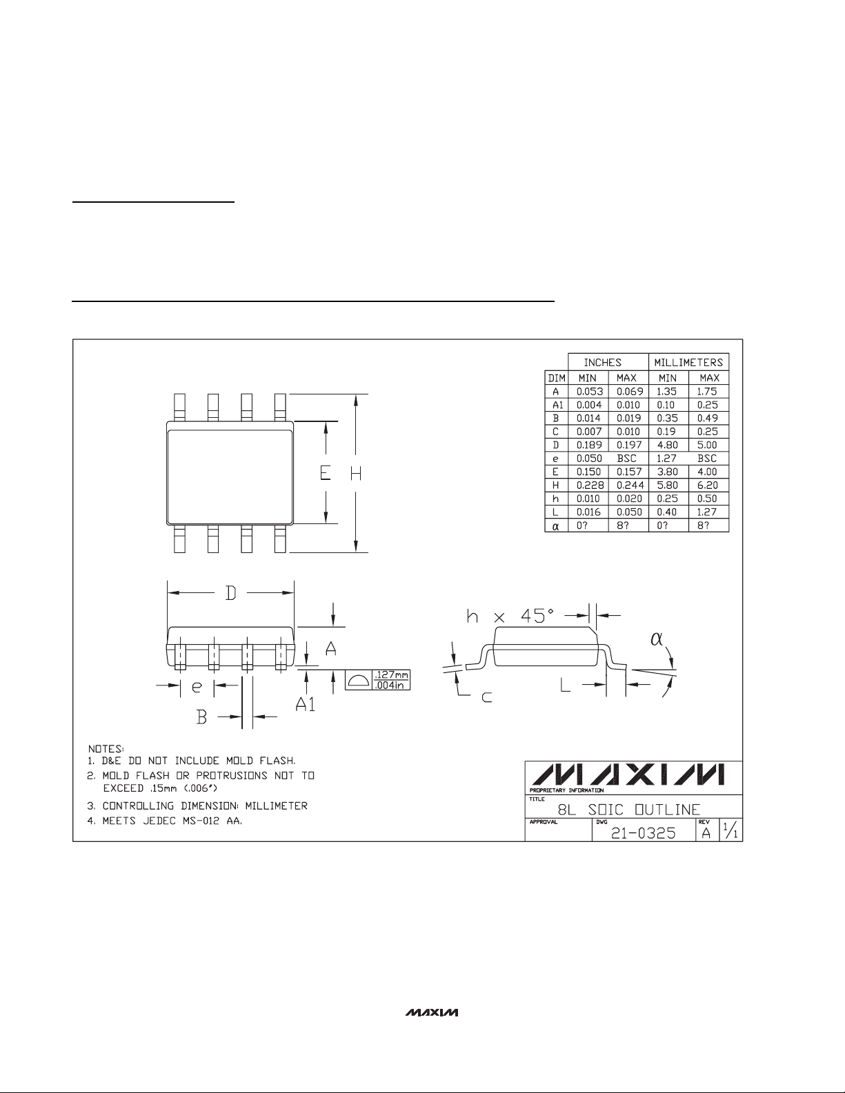
Package Information
3x3.EPS
9LUCSP
 Loading...