

Page 1
General Description
The MAX6668/MAX6670 remote-junction thermal
switches with an internal power transistor drive a cooling fan rated for supply voltages up to +12V and
250mA. These devices measure the temperature of an
external P-N junction (typically a diode-connected transistor) and turn on the fan power switch when the
remote temperature rises above a factory-programmed
threshold. Self-contained and requiring no software
development, the MAX6668/MAX6670 are simple
“drop-in” fan-control solutions for a variety of systems.
The MAX6670 features an open-drain WARN output
that goes active when the remote temperature exceeds
the factory-programmed fan activation threshold by
+15°C. The MAX6670 features an open-drain OT output
that goes active when the remote temperature exceeds
the factory-programmed threshold by +30°C. The
MAX6668/MAX6670 provide a fan-control input,
FORCEON, that allows the fan to be driven externally,
regardless of temperature.
Available temperature thresholds range from +40°C to
+75°C in 5°C increments. Hysteresis is preset to 8°C on
the MAX6668 or pin selectable to 4°C, 8°C, or 12°C
using a three-level logic input on the MAX6670.
Temperature threshold accuracy is ±1°C (typ) and
±2.2°C (max) for remote-junction temperatures from
+40°C to +75°C.
The MAX6668/MAX6670 operate from a +3V to +3.6V
power supply, and are specified over the automotive
temperature range (-40°C to +125°C). The MAX6668 is
offered in an 8-pin µMAX package and the MAX6670 is
available in a space-saving 10-pin µMAX package.
Applications
Notebook and Desktop Computers
Network Switches
PC Power Supplies
Laboratory Instruments
Card Racks
Temperature Alarms
Fan Controls
Features
♦ +12V, 250mA Integrated Fan Driver
♦ No Calibration Required
♦ Pin-Selectable 4°C, 8°C, or 12°C Hysteresis
(MAX6670)
♦ Factory-Programmed Temperature Thresholds
from +40°C to +75°C
♦ Overtemperature Warning Signals
♦ 110µA (typ) Supply Current
♦ Space-Saving 8-Pin and 10-Pin µMAX Packages
MAX6668/MAX6670
Remote Temperature Switches with Integrated
Fan Controller/Driver
________________________________________________________________ Maxim Integrated Products 1
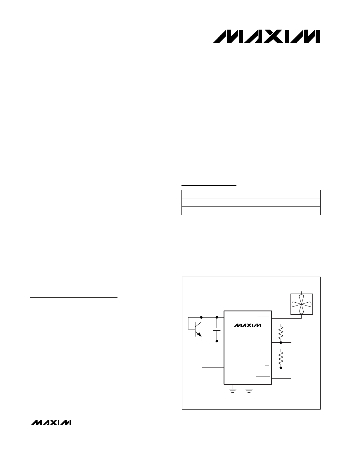
Typical Applications Circuit
Ordering Information
19-2133; Rev 0; 8/01
Pin Configuration appears at end of data sheet.
Typical Operating Circuit appears at end of data sheet.
For pricing, delivery, and ordering information, please contact Maxim/Dallas Direct! at
1-888-629-4642, or visit Maxim’s website at www.maxim-ic.com.
*These parts are offered in eight standard temperature versions from +40°C through +75°C in 5°C increments. To complete the suffix information, select an available temperature trip
point in degrees centigrade and fill in the blank. For example,
the MAX6670AUB065 describes a MAX6670 in a 10-pin µMAX
package with +65°C trip point.
PART* TEMP. RANGE PIN-PACKAGE
MAX6668AUA_ _ _ -40°C to +125°C 8 µMAX
MAX6670AUB_ _ _ -40°C to +125°C 10 µMAX
+12V
250mA
FAN
V
DD
10kΩ
V
DD
10kΩ
OT
2N3904
2200pF
+3.3V
V
DXP
C
S
DXN
HYST
DD
MAX6670
FANOUT
WARN
V
GND
PGND
FORCEON
DD
Page 2
MAX6668/MAX6670
Remote Temperature Switches with Integrated
Fan Controller/Driver
2 _______________________________________________________________________________________
ABSOLUTE MAXIMUM RATINGS
ELECTRICAL CHARACTERISTICS
(VDD= +3V to +3.6V, TA= -40°C to +125°C, unless otherwise noted. Typical values are at VDD= +3.3V and TA= +25°C.)
Stresses beyond those listed under “Absolute Maximum Ratings” may cause permanent damage to the device. These are stress ratings only, and functional
operation of the device at these or any other conditions beyond those indicated in the operational sections of the specifications is not implied. Exposure to
absolute maximum rating conditions for extended periods may affect device reliability.
VDDto GND..............................................................-0.3V to +6V
PGND to GND .......................................................-0.3V to +0.3V
FANOUT to GND ....................................................-0.3V to +15V
DXN to GND ..........................................................-0.3V to +0.8V
DXP, WARN, HYST, FORCEON, OT...........-0.3V to (V
DD
+ 0.3V)
Current into V
DD
, GND, DXP, DXN, WARN, HYST,
FORCEON, OT..............................................................±20mA
Current into FANOUT, PGND ........................................ ±300mA
Continuous Power Dissipation (T
A
= +70°C)
8-Pin µMAX (derate 4.1mW/°C above +70°C).............333mW
10-Pin µMAX (derate 5.6mW/°C above +70°C) ...........444mW
Operating Temperature Range .........................-40°C to +125°C
Storage Temperature Range .............................-60°C to +150°C
Junction Temperature......................................................+150°C
Lead Temperature (soldering, 10s) .................................+300°C
POWER SUPPLY
Power-Supply Range V
Average Supply Current I
Operating Current During sampling 400 650 µA
Power-On Reset (POR) Threshold POR VDD falling edge 1 1.5 2.0 V
POR Threshold Hysteresis 50 mV
TEMPERATURE SENSOR
FANOUT Temperature
Threshold Accuracy
FANOUT Temperature
Threshold Hysteresis
WARN Temperature Threshold
(MAX6670 Only)
OT Temperature Threshold
(MAX6670 Only)
Supply Sensitivity of Temperature
Threshold
Temperature Sample Frequency 3.3 4 Hz
FAN DRIVE OUTPUT
FANOUT Output Voltage Low V
Thermal Shutdown 170 °C
Thermal Shutdown Hysteresis 20 °C
LOGIC INPUT/OUTPUT
FORCEON Input High Voltage V
PARAMETER SYMBOL CONDITIONS MIN TYP MAX UNITS
DD
DD
TRJ = +40°C to +75°C (Note 1),
T
= 0°C to +85°C, VDD = +3.3V
∆T
T
HYST
TH
OL
IH
A
TRJ = +40°C to +75°C (Note 1),
= -40°C to +125°C, VDD = +3.3V
T
A
HYST = GND 4
MAX6670
MAX6668 8
Relative to FANOUT temperature threshold +15 °C
Relative to FANOUT temperature threshold +30 °C
I
= 250mA 0.5 1 V
SINK
HYST = float 8
HYST = V
DD
3 3.6 V
110 200 µA
±1 ±2.2
±1 ±4
12
1 1.6 °C/V
0.8 x
V
DD
°C
°C
V
Page 3
MAX6668/MAX6670
Remote Temperature Switches with Integrated
Fan Controller/Driver
_______________________________________________________________________________________ 3
ELECTRICAL CHARACTERISTICS (continued)
(VDD= +3V to +3.6V, TA= -40°C to +125°C, unless otherwise noted. Typical values are at VDD= +3.3V and TA= +25°C.)
Note 1: T
RJ
is the temperature of the remote P-N junction.
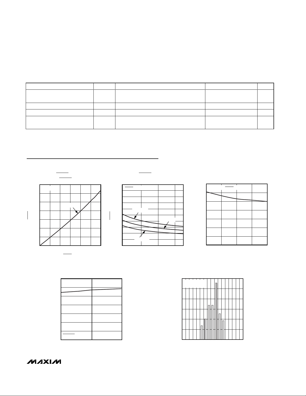
Typical Operating Characteristics
(TA= +25°C, unless otherwise noted.)
0
0.2
0.1
0.4
0.3
0.6
0.5
0.7
0 100 15050 200 250 300
FANOUT CURRENT
vs. FANOUT VOLTAGE
MAX6668/70 toc01
I
FANOUT
(mA)
V
FANOUT
(V)
TA = +25°C
VDD = +3.3V
0
0.6
0.4
0.2
0.8
1.0
1.2
1.4
1.6
1.8
2.0
2.0 2.5
3.0
3.5
FANOUT VOLTAGE
vs. SUPPLY VOLTAGE
MAX6668/70 toc02
VDD (V)
V
FANOUT
(V)
TA = +105°C
TA = +65°C
TA = +25°C
I
FANOUT
= 250mA
0
40
20
80
60
120
100
140
SUPPLY CURRENT
vs. TEMPERATURE
MAX6668/70 toc03
TEMPERATURE (°C)
I
DD
(µA)
0 255075100
VDD = +3.3V, I
FANOUT
= 250mA
0
40
20
80
60
120
100
140
3.0 3.63.3
SUPPLY CURRENT
vs. SUPPLY VOLTAGE
MAX6668/70 toc04
VDD (V)
I
DD
(µA)
FORCEON = V
DD
0
5
20
15
10
25
30
-1.00
-0.25
-0.50 0.50-0.75 0 0.25 0.75
1.00
TEMPERATURE THRESHOLD ERROR
MAX6668/70 toc05
THRESHOLD ERROR (°C)
PERCENTAGE OF SAMPLES (%)
MAX6670AUB040
119 SAMPLES
FORCEON Input Low Voltage V
FORCEON Input Bias Current V
WARN, OT Output Voltage Low V
WARN, OT Output High Leakage
Current
PARAMETER SYMBOL CONDITIONS MIN TYP MAX UNITS
IL
I
OL
I
OH
SINK
V
FORCEON
= VDD or GND 1 µA
= 6mA 0.5 V
or VOT = +5.5V 1 µA
WARN
0.2 x
V
DD
V
Page 4
MAX6668/MAX6670
Detailed Description
The MAX6668/MAX6670 are simple fan controllers/drivers that turn on an internal power transistor when the
sensed temperature of an external P-N junction
exceeds a factory-set threshold. By connecting a small
(up to +12V/250mA nominal) cooling fan to FANOUT, a
simple on/off fan-control system is created. Do not connect the fan to a power supply of higher than 12V nominal, 15V maximum.
FANOUT
Driver and
FORCEON
Controller
FANOUT Fan-Driver Output
FANOUT is an open-drain output that sinks greater than
250mA of current to turn on the fan, either when the fan
trip threshold is exceeded or the fan is forced on by driving FORCEON low.
FORCEON Fan-Control Input
Drive FORCEON low to turn on the fan when the
MAX6670’s remote-sensing junction temperature is less
than the fan trip threshold temperature. This overrides
the internal control circuitry and allows for an external
device to activate the fan.
Overtemperature Alarm Outputs
WARN Output (MAX6670 Only)
WARN is an active-low, open-drain digital output that
indicates when the external P-N junction’s temperature
exceeds 15°C above the fan trip threshold. The WARN
output serves as a warning that the system temperature
has continued to rise well above the fan activation temperature.
OT Output (MAX6670 Only)
OT is an active-low, open-drain digital output that indicates when the external P-N junction’s temperature
exceeds 30°C above the fan trip threshold. OT serves
as a thermal shutdown output to the system in case of
excessive temperature rise.
Remote Temperature Switches with Integrated
Fan Controller/Driver
4 _______________________________________________________________________________________
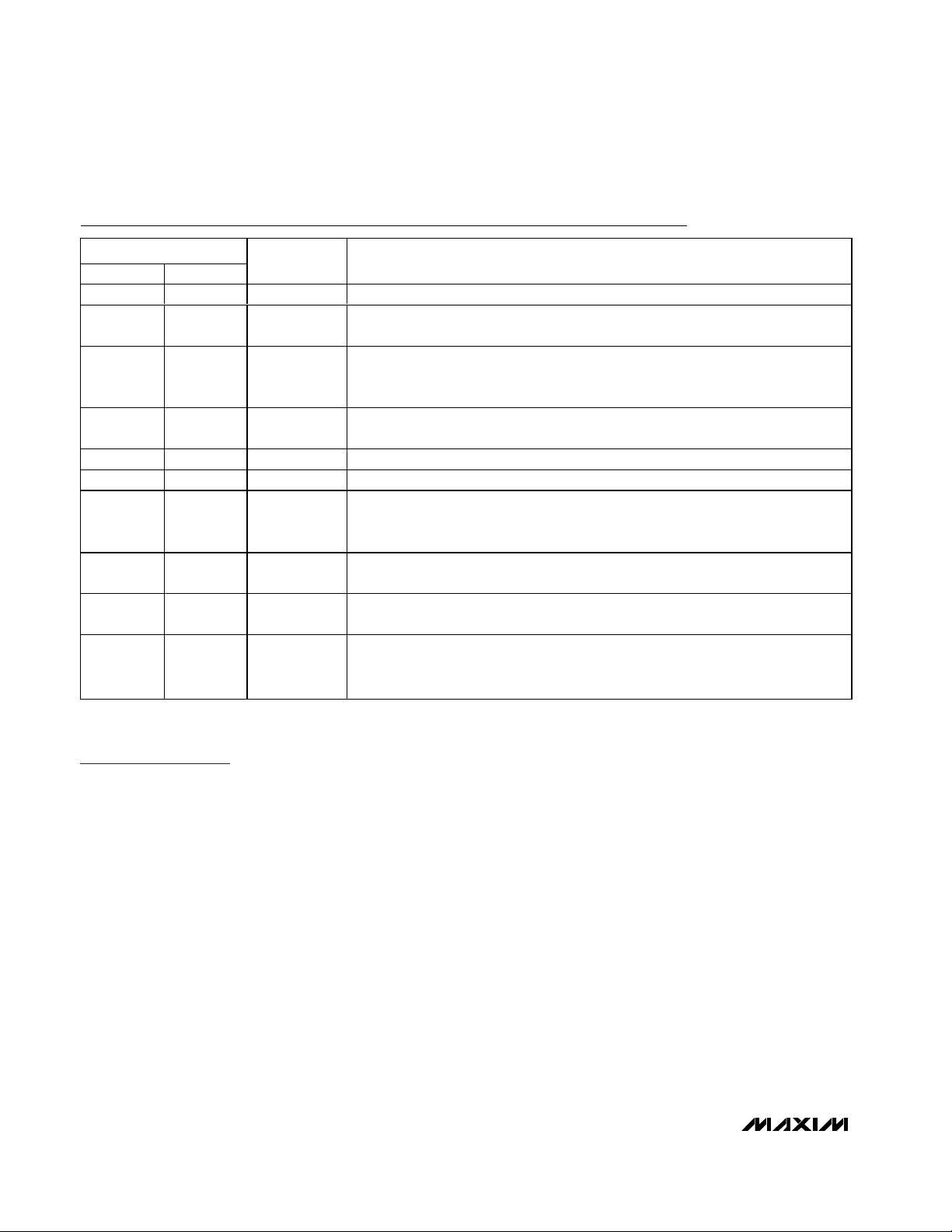
Pin Description
PIN
MAX6668 MAX6670
1 1 PGND Power Ground. PGND is the power ground for the FANOUT power MOSFET switch.
25FORCEON
3 3 DXP
44DXN
5, 7 7 GND Ground
68VDDPositive Power Supply
810FANOUT
—2WARN
—6 OT
— 9 HYST
NAME FUNCTION
Fan-Control Input. Drive FORCEON high for normal operation. Drive FORCEON low
to force fan on.
Current Source Positive Input. Connect to the anode of the external diodeconnected transistor. Do not leave DXP floating. Connect a 2200pF capacitor
between DXP and DXN for noise filtering.
Current Sink Negative Input. Connect to the cathode of the external diodeconnected transistor. DXN is internally biased to a diode voltage drop.
Fan-Drive Output. FANOUT is an open-drain power MOSFET that sinks up to 250mA
current to turn on the fan when the sensed temperature exceeds the fan trip
threshold or the fan is forced on by driving FORCEON low.
Temperature Warning Output. WARN is an open-drain output that goes low when
the sensed junction temperature is 15°C higher than the fan trip threshold.
Overtemperature Output. OT is an open-drain output that goes low when the sensed
junction temperature is 30°C higher than the fan trip threshold.
Hysteresis Control Input. HYST is a three-level logic input for controlling the fandrive comparator’s hysteresis. Connect HYST to GND for 4°C hysteresis, to V
12°C hysteresis, or leave floating for 8°C hysteresis.
for
DD
Page 5
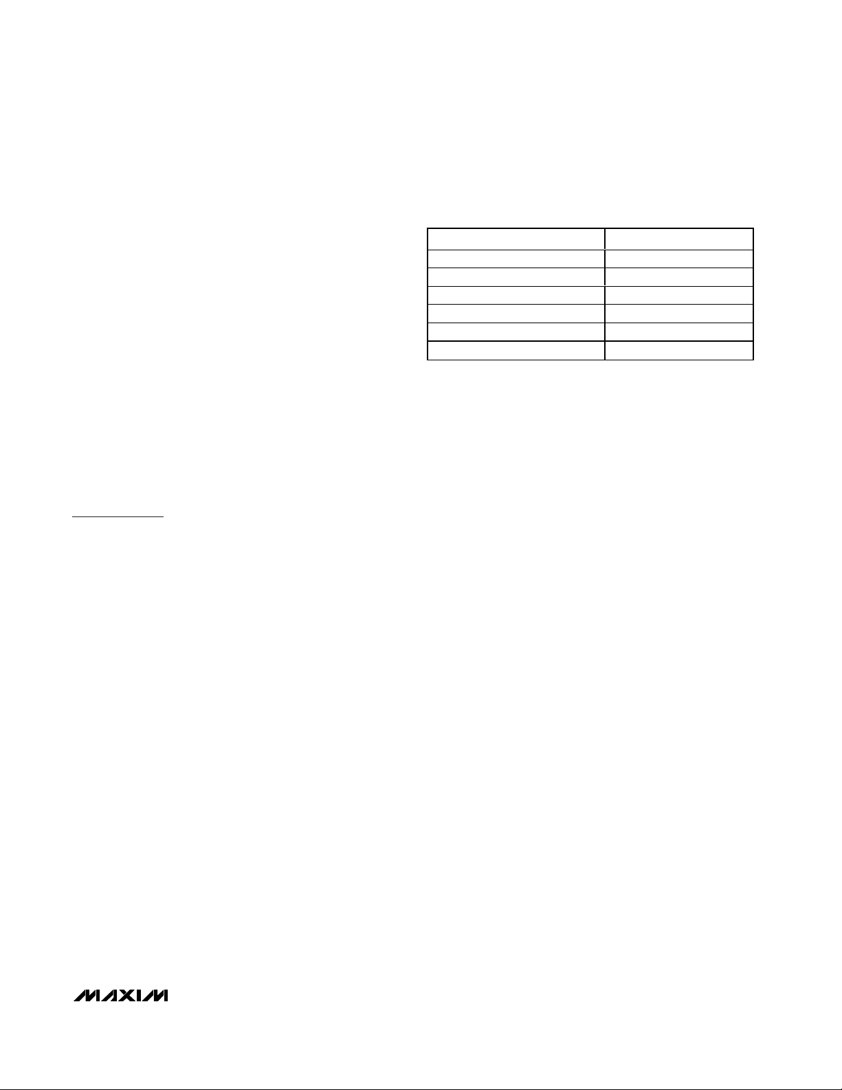
Hysteresis Input
The temperature comparator has hysteresis to prevent
small temperature changes near the threshold temperature from causing the fan to turn on and off repeatedly
over short periods of time. The FANOUT pin goes
active and powers the fan when the external P-N junction’s temperature exceeds the factory-programmed
trip temperature. As the cooling fan operates, the circuit board temperature should decrease, which causes
the external P-N junction’s temperature to decrease.
When the P-N junction’s temperature is equal to the trip
threshold minus the hysteresis, the FANOUT pin turns
the fan off, removing power from the fan. For the
MAX6670, HYST is a three-level logic input for controlling the fan-drive comparator’s hysteresis. Connect
HYST to GND to select 4°C hysteresis, to V
DD
to select
12°C hysteresis, or leave floating to select 8°C hysteresis. The MAX6668 has a built-in hysteresis of 8°C. This
allows the amount of hysteresis to be matched to the
cooling and noise requirements of the system. Figure 1
shows the temperature trip threshold hysteresis.
Applications Information
Remote-Diode Selection
The MAX6668/MAX6670 directly measure the die temperature of CPUs and other ICs that have on-board
temperature-sensing diodes (see Typical Operating
Circuit) or they can measure the temperature of a discrete diode-connected transistor. For best accuracy,
the discrete transistor should be a small-signal device
with its collector and base connected together. Several
satisfactory discrete sensing transistors are shown in
Table 1.
The sensing transistor must be a small-signal type with
a relatively high forward voltage. Otherwise, the DXP
input voltage range may be violated. The forward voltage at the highest expected temperature must be
greater than 0.25V at 10µA, and at the lowest expected
temperature, forward voltage must be less than 0.95V
at 100µA. Do not use large power transistors. Also,
ensure that the base resistance is less than 100Ω. Tight
specifications for forward current gain (50 < BF< 150,
for example) indicate that the manufacturer has good
process controls and that the transistors have consistent V
BE
characteristics.
Noise-Filtering Capacitor
In noisy environments, high-frequency noise can be
attenuated using an external 2200pF capacitor located
at the DXP and DXN pins. Larger capacitor values may
be used for additional filtering, but do not exceed
3300pF; excessive capacitance increases error. Figure
2 shows the recommended DXP/DXN PC traces.
Bypassing and Layout
The location of the remote-sensing junction in the system affects the MAX6668/MAX6670s’ operation. When
using a discrete temperature-sensing transistor, place
the sensing junction close to major heat-generating
components, such as a high-speed CPU or a power
device.
To minimize noise and other errors, follow the guidelines below:
1) Place the MAX6668/MAX6670 as close as possible
to the remote diode. In a noisy environment, such as
a computer motherboard, this distance can be 10cm
to 20cm (typ) or more as long as the worst noise
sources (such as CRTs, clock generators, memory
buses, and ISA/PCI buses) are avoided. In general,
minimize the distance to the remote-sensing junction.
2) Do not route the DXP/DXN traces next to the deflection coils of a CRT. Also, do not route the traces
across a fast memory bus, which can introduce
+30°C error or more, even with good filtering.
3) Route the DXP and DXN traces in parallel and in
close proximity to each other, away from any highvoltage traces, such as +12VDC. Avoid leakage currents from PC board contamination, since a 20MΩ
leakage path from DXP to GND causes about +1°C
error.
4) Connect guard traces to GND on either side of the
DXP/DXN traces (Figure 2). With guard traces in
place, routing near high-voltage traces is no longer
an issue.
5) Route through as few vias and crossunders as possi-
ble to minimize copper/solder thermocouple effects.
6) Use wide traces where possible. Narrow traces are
more inductive and tend to pick up radiated noise.
7) Do not use copper as an EMI shield. Only ferrous
materials such as steel work well. Placing a copper
ground plane between the DXP/DXN traces and
MAX6668/MAX6670
Remote Temperature Switches with Integrated
Fan Controller/Driver
_______________________________________________________________________________________ 5
Table 1. Remote-Sensor Transistor
Manufacturers
MANUFACTURER MODEL NO.
Central Semiconductor (USA) CMPT3904
ON Semiconductor (USA) 2N3904, 2N3906
Rohm Semiconductor (USA) SST3904
Samsung (Korea) KST3904-TF
Siemens (Germany) SMBT3904
Zetex (England) FMMT3904CT-ND
Page 6
MAX6668/MAX6670
other traces carrying high-frequency noise signals
does not help reduce EMI.
The MAX6668/MAX6670s’ PGND is the ground return
for the fan driver. Bypass VDDto GND with a 1µF
capacitor located as close to VDDas possible. Add
additional bypass capacitors for long VDDand GND
lines.
Chip Information
TRANSISTOR COUNT: 8113
PROCESS: BiCMOS
Remote Temperature Switches with Integrated
Fan Controller/Driver
6 _______________________________________________________________________________________
Figure 2. Recommended DXP/DXN PC Traces
Figure 1. Temperature Trip Threshold Hysteresis
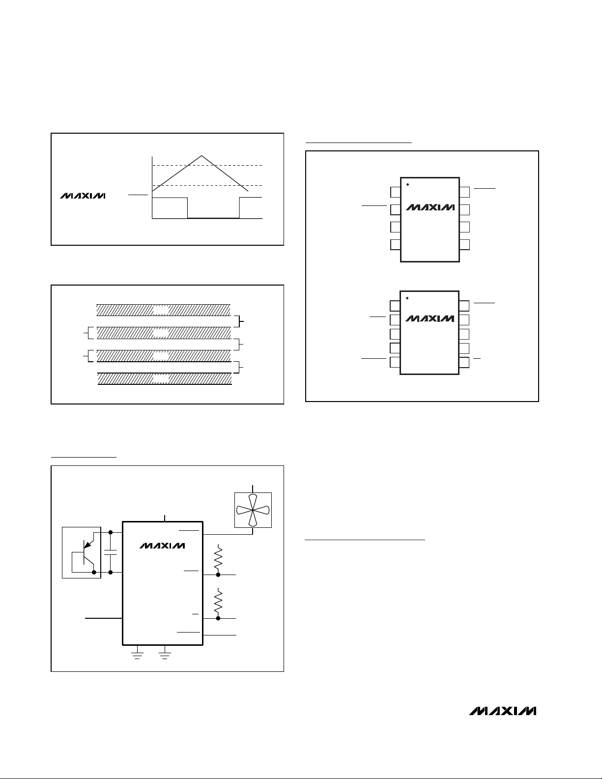
Typical Operating Circuit
Pin Configurations
MAX6668
MAX6670
TRIP TEMPERATURE
TRIP TEMPERATURE
– HYSTERESIS
FANOUT
TIME
TOP VIEW
PGND
DXP
1
2
87FANOUT
GNDFORCEON
MAX6668
3
4
V
6
DD
5
GNDDXN
GND
10MILS
DXP
10MILS
CPU
DXP
DXN
DXN
GND
+3V TO +3.6V
V
DD
MAX6670
FANOUT
WARN
V
DD
V
DD
10MILS
MINIMUM
10MILS
+4.5V TO +12V
µMAX
PGND
WARN
DXP
1
2
MAX6670
3
4
5
10
9
8
7
6
FANOUT
HYST
V
DD
GNDDXN
OTFORCEON
µMAX
HYST
GND
PGND
OT
FORCEON
V
DD
Page 7
MAX6668/MAX6670
Remote Temperature Switches with Integrated
Fan Controller/Driver
_______________________________________________________________________________________ 7
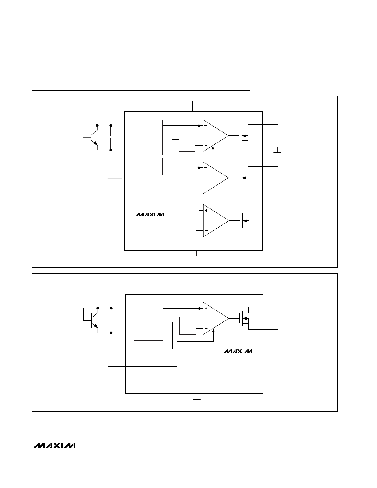
Functional Diagrams
C
S
DXP
DXN
HYST
FORCEON
TEMP
SENSOR
4°C, 8°C,
12°C
HYSTERESIS
MAX6670
T
FAN
T
FAN
+15°C
T
FAN
+30°C
V
DD
FANOUT
PGND
WARN
OT
GND
V
DD
DXP
C
S
DXN
TEMP
SENSOR
8°C
HYSTERESIS
T
FAN
FANOUT
PGND
MAX6668
FORCEON
GND
Page 8

MAX6668/MAX6670
Remote Temperature Switches with Integrated
Fan Controller/Driver
Maxim cannot assume responsibility for use of any circuitry other than circuitry entirely embodied in a Maxim product. No circuit patent licenses are
implied. Maxim reserves the right to change the circuitry and specifications without notice at any time.
8 _____________________Maxim Integrated Products, 120 San Gabriel Drive, Sunnyvale, CA 94086 408-737-7600
© 2001 Maxim Integrated Products Printed USA is a registered trademark of Maxim Integrated Products.
Package Information
8LUMAXD.EPS
10LUMAX.EPS
 Loading...