

Page 1
For free samples & the latest literature: http://www.maxim-ic.com, or phone 1-800-998-8800.
For small orders, phone 1-800-835-8769.
General Description
The MAX6576/MAX6577 are low-cost, low-current temperature sensors with a single-wire output. The MAX6576
converts the ambient temperature into a square wave
with a period proportional to absolute temperature (°K).
The MAX6577 converts the ambient temperature into a
square wave with a frequency proportional to absolute
temperature. The MAX6576 offers accuracy of ±3°C at
+25°C, ±4.5°C at +85°C, and ±5°C at +125°C. The
MAX6577 offers accuracy of ±3°C at +25°C, ±3.5°C at
+85°C, and ±4.5°C at +125°C.
Both devices feature a single-wire output that minimizes
the number of pins necessary to interface with a microprocessor. The period/frequency range of the output
square wave can be selected by hard-wiring the two
time-select pins (TS0, TS1) to either VDDor GND. The
MAX6576/MAX6577 are available in space-saving 6-pin
SOT23 packages.
Applications
Critical µP and µC Temperature Monitoring
Portable Battery-Powered Equipment
Cell Phones
Battery Packs
Hard Drives/Tape Drives
Networking and Telecom Equipment
Medical Equipment
Automotive
Features
♦ Simple Single-Wire Output
♦ Two Output Types Available
Temperature to Period (µs) (MAX6576)
Temperature to Frequency (Hz) (MAX6577)
♦ ±0.8°C Accuracy at +25°C (±3°C max)
♦ No External Components
♦ Operates from +2.7V to +5.5V Supply Voltage
♦ Low 140µA Typical Supply Current
♦ Standard Operating Temperature Range:
-40°C to +125°C
♦ Small 6-Pin SOT23 Package
MAX6576/MAX6577
SOT Temperature Sensors with
Period/Frequency Output
________________________________________________________________
Maxim Integrated Products
1
+2.7V TO +5.5V
GND
TS0
TS1
OUT
0.1µF
0.1µF
V
DD
MAX6576
MAX6577
µP
GND
I/O
V
CC
19-1484; Rev 0; 4/99
PART
MAX6576ZUT
MAX6577ZUT
-40°C to +125°C
-40°C to +125°C
TEMP. RANGE
PIN-
PACKAGE
6 SOT23
6 SOT23
Typical Operating Circuit
Ordering Information
SOT
TOP MARK
AABI
AABJ
GND
TS0N.C.
16OUT
5 TS1
V
DD
MAX6576
MAX6577
SOT23-6
TOP VIEW
2
34
Pin Configuration
Page 2
MAX6576/MAX6577
SOT Temperature Sensors with
Period/Frequency Output
2 _______________________________________________________________________________________
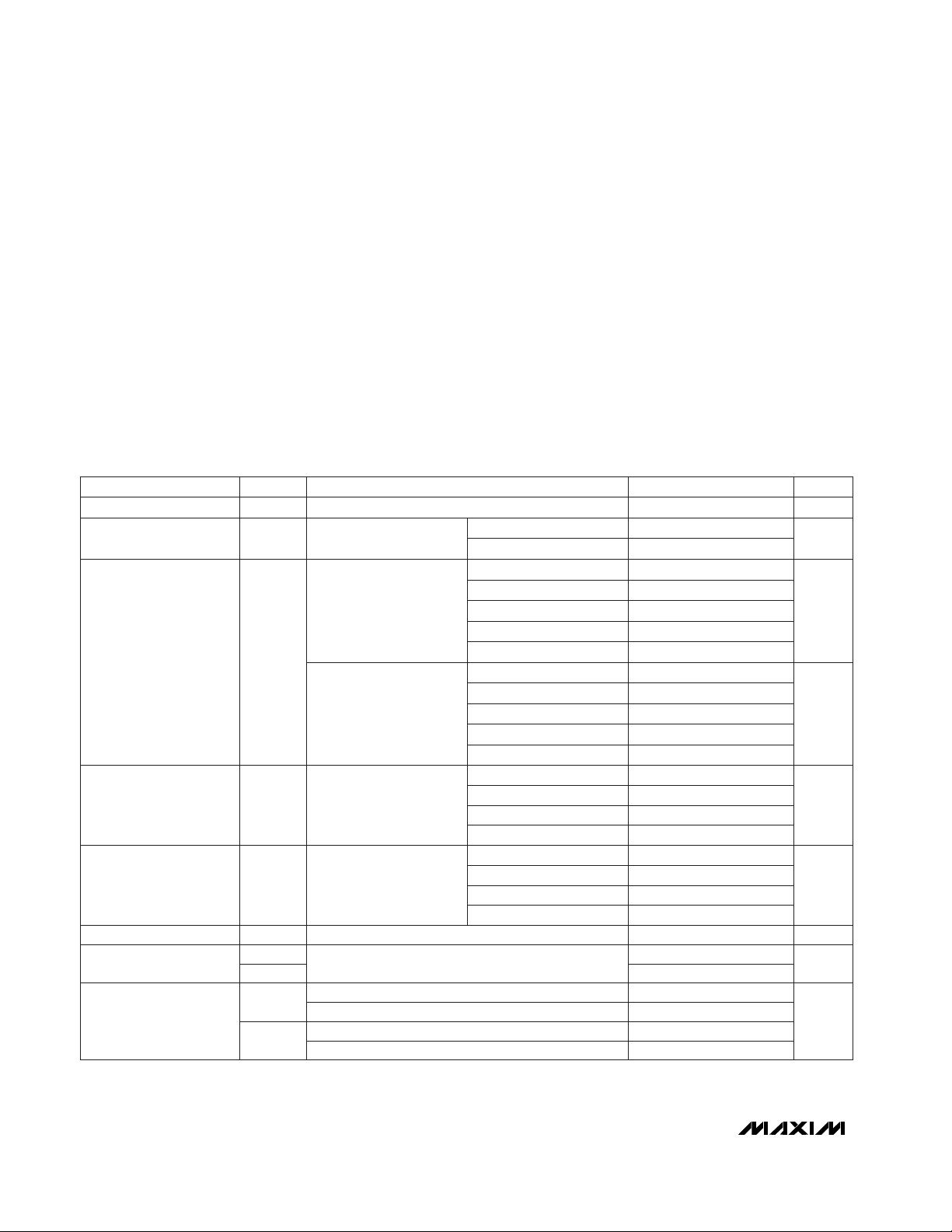
ABSOLUTE MAXIMUM RATINGS
ELECTRICAL CHARACTERISTICS
(VDD= +2.7V to +5.5V, TA= -40°C to +125°C, unless otherwise noted. Typical values are specified at TA= +25°C and VDD= +5V,
unless otherwise noted.)
Stresses beyond those listed under “Absolute Maximum Ratings” may cause permanent damage to the device. These are stress ratings only, and functional
operation of the device at these or any other conditions beyond those indicated in the operational sections of the specifications is not implied. Exposure to
absolute maximum rating conditions for extended periods may affect device reliability.
Note 1: See the Temperature Accuracy histograms in the
Typical Operating Characteristics
.
Note 2: The output duty cycle is guaranteed to be 50% by an internal flip-flop.
Terminal Voltage (with respect to GND)
V
DD
......................................................................-0.3V to +6V
TS1, TS0, OUT.......................................-0.3V to (V
DD
+ 0.3V)
Input/Output Current, All Pins...........................................±20mA
Continuous Power Dissipation (T
A
= +70°C)
6-pin SOT23 (derate 7.10mW/°C above +70°C).........571mW
Operating Temperature Range .........................-40°C to +125°C
Storage Temperature Range.............................-65°C to +150°C
Lead Temperature (soldering, 10sec).............................+300°C
MAX6576
VDD= 5.5V
VDD> 2.7V, I
SINK
= 1.2mA
VDD> 4.5V, I
SINK
= 3.2mA
MAX6576,
T (temp) in °K,
Figure 1
MAX6577
CONDITIONS
0.3
V
0.4
V
OL
OUT Voltage
2.3V
IH
V
0.8V
IL
Time-Select Pin Logic
Levels
0.5OUT Duty Cycle (Note 2)
640T
°C
-7.5 ±1.1 +7.5
Temperature Sensor
Error (Note 1)
µA
140 250
I
DD
V2.7 5.5V
DD
VDDRange
Supply Current
160T
40T
µs
10T
t
OUT
Output Clock Period
-3.0 ±0.8 +3.0
-5.5 ±0.9 +5.5
-3.0 ±0.8 +3.0
-7.5 ±1.1 +7.5
-6.5 ±0.9 +6.5
UNITSMIN TYP MAXSYMBOLPARAMETER
TA= -20°C
TA= 0°C
TA= +25°C
TA= -20°C
TA= 0°C
TA= +25°C
V
TS1
= VDD, V
TS0
= V
DD
MAX6577,
T (temp) in °K,
Figure 2
V
TS1
= VDD, V
TS0
= V
DD
T/16
T/4
1T
Hz
4T
f
OUT
Output Clock Frequency
VDD> 4.5V, I
SRC
= 800µA VDD- 1.5
V
OH
VDD> 2.7V, I
SRC
= 500µA 0.8V
DD
V
TS1
= GND, V
TS0
= GND
V
TS1
= GND, V
TS0
= V
DD
V
TS1
= VDD, V
TS0
= GND
V
TS1
= GND, V
TS0
= GND
V
TS1
= GND, V
TS0
= V
DD
V
TS1
= VDD, V
TS0
= GND
TA= -40°C to +85°C
TA= -40°C to +125°C 400
°C
-3.5 ±0.5 +3.5TA= +85°C
-4.5 ±0.5 +4.5TA= +125°C
TA= +85°C -4.5 ±0.5 +4.5
TA= +125°C -5.0 ±0.5 +5.0
Page 3
MAX6576/MAX6577
SOT Temperature Sensors with
Period/Frequency Output
_______________________________________________________________________________________
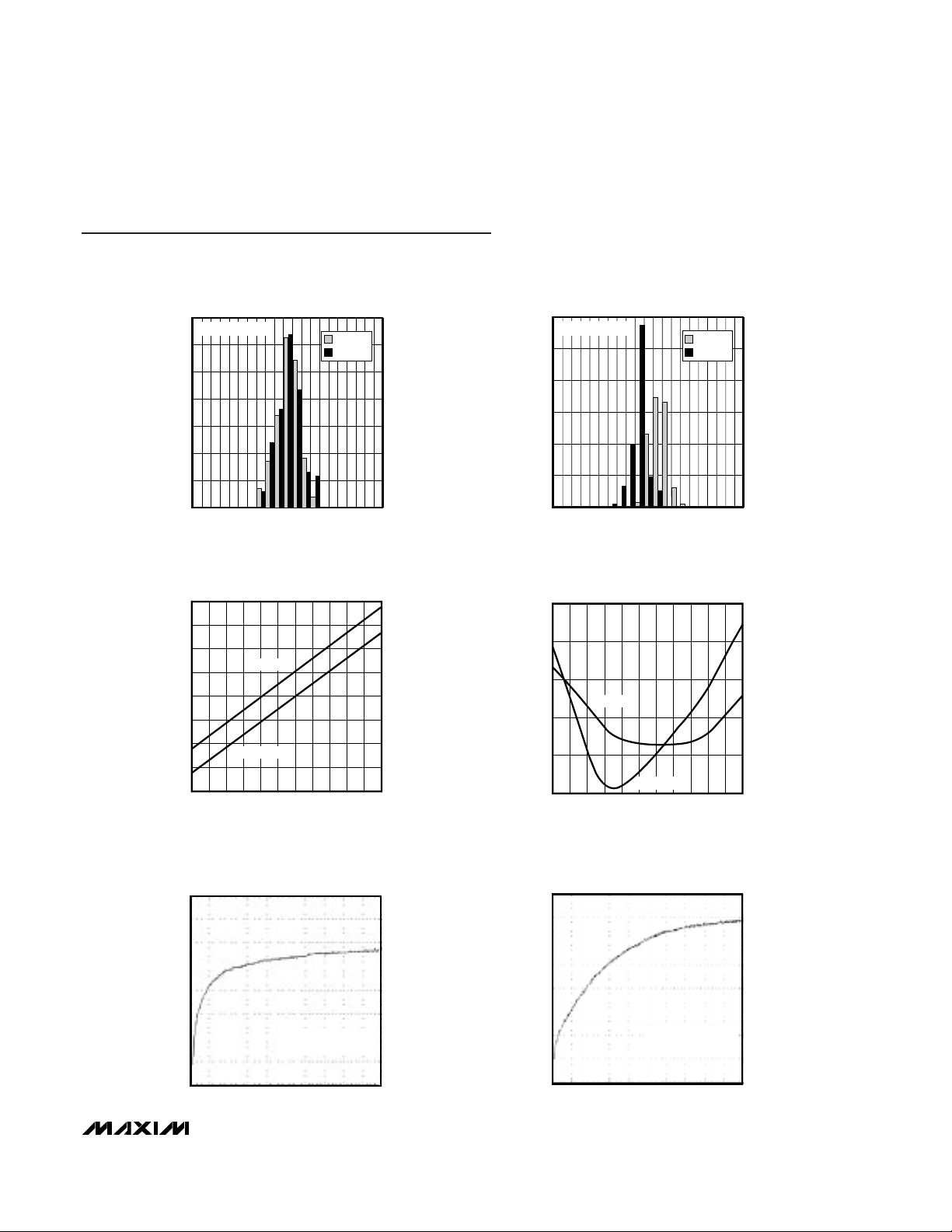
3
0
10
5
15
20
25
30
35
-5 -3 -2-4 -1012345
TEMPERATURE ACCURACY
(T
A
= +25°C)
MAX6576 toc01
ACCURACY (°C)
PERCENTAGE OF PARTS SAMPLED (%)
MAX6576
MAX6577
SAMPLE SIZE = 200
0
20
10
30
40
50
60
-5 -3 -2-4 -1012345
TEMPERATURE ACCURACY
(T
A
= +85°C)
MAX6576 toc01
ACCURACY (°C)
PERCENTAGE OF PARTS SAMPLED (%)
MAX6576
MAX6577
SAMPLE SIZE = 200
100
130
120
110
150
140
170
160
180
-40 -10 5 20-25 35 50 65 80 95 110 125
SUPPLY CURRENT vs. TEMPERATURE
MAX6576/77toc02
TEMPERATURE (°C)
SUPPLY CURRENT (µA)
MAX6577
MAX6576
-1.0
0
-0.5
1.0
0.5
1.5
-40 -10 5 20-25 35 50 65 80 95 110 125
ACCURACY vs. TEMPERATURE
MAX6575 toc04
TEMPERATURE (°C)
ACCURACY (°C)
MAX6576
MAX6577
+15°C/div
+100°C
+25°C
THERMAL STEP RESPONSE
IN PERFLUORINATED FLUID
MAX6576/77 toc05
5sec/div
MOUNTED ON 0.75 in.
2
OF 2oz. COPPER
+12.5°C/div
+100°C
+25°C
THERMAL STEP RESPONSE
IN STILL AIR
MAX6576/77 toc06
20sec/div
MOUNTED ON 0.75 in.
2
OF 2oz. COPPER
Typical Operating Characteristics
(VDD= +5V, TA = +25°C, unless otherwise noted.)
Page 4

Table 1. MAX6576 Time-Select Pin
Configuration
Table 2. MAX6577 Time-Select Pin
Configuration
MAX6576/MAX6577
SOT Temperature Sensors with
Period/Frequency Output
4 _______________________________________________________________________________________
Pin Description
Detailed Description
The MAX6576/MAX6577 low-cost, low-current (140µA
typ) temperature sensors are ideal for interfacing with
microcontrollers (µCs) or microprocessors (µPs). The
MAX6576 converts ambient temperature into a 50% dutycycle square wave with a period proportional to absolute
temperature. The MAX6577 converts ambient temperature into a 50% duty-cycle square wave with a frequency
proportional to absolute temperature. Time-select pins
(TS1, TS0) permit the internal temperature-controlled
oscillator (TCO) to be scaled by four preset multipliers.
The MAX6576/MAX6577 feature a single-wire interface to
minimize the number of port pins necessary for interfacing with a µP.
MAX6576 Characteristics
The MAX6576 temperature sensor converts temperature to period. The output of the device is a freerunning, 50% duty-cycle square wave with a period that
is proportional to the absolute temperature (°K) of the
device (Figure 1). The MAX6576 has a push/pull CMOS
output with sharp edges. The speed of the output
square wave can be selected by hard-wiring TS1 and
TS0 as shown in Table 1. One of four scaled output
periods can be selected using TS1 and TS0.
MAX6577 Characteristics
The MAX6577 temperature sensor converts temperature to frequency. The output of the device is a freerunning, 50% duty-cycle square wave with a frequency
that is proportional to the absolute temperature (°K) of
the device (Figure 2). The MAX6577 has a push/pull
CMOS output with sharp edges. The speed of the output square wave can be selected by hard-wiring TS1
and TS0 as shown in Table 2. One of four scaled output
frequencies can be selected using TS1 and TS0.
GND
GND
V
DD
GND
V
DD
GND 10
40
160
V
DD
V
DD
640
TS1 TS0
SCALAR MULTIPLIER
(µs/°K)
Note: The temperature, in °C, may be calculated as follows:
GND
GND
V
DD
GND
V
DD
GND 4
1
1/4
TS1 TS0
SCALAR MULTIPLIER
(Hz/°K)
V
DD
V
DD
1/16
1
2
3
Positive Supply Voltage
Ground
No Connection. Connect pin to GND or leave open.
FUNCTION
4, 5
Time-Select Pins. TS1 and TS0 set the temperature scale factor by connecting TS1 and TS0 to
either VDDor GND. See Tables 1 and 2.
PIN
N.C.
GND
V
DD
NAME
TS1, TS0
Note: The temperature, in °C, may be calculated as follows:
T( C)
period( s)
scalar mulitplier( s/ K)
273.15 K°=
°
−°
µ
µ
T( C)
frequency(Hz)
scalar mulitplier(Hz/ K)
273.15 K°=
°
−°
6
Square-Wave Output with a Clock Frequency Proportional to Absolute Temperature (°K) (MAX6577)
OUT
Square-Wave Output with a Clock Period Proportional to Absolute Temperature (°K) (MAX6576)
Page 5

Applications Information
Quick-Look Circuits
Figure 3 shows a quick-look application circuit for the
MAX6576 using a universal counter measuring period.
TS1 and TS0 are both tied to ground to select a scalar
multiplier of 10µs/°K. The MAX6576 converts the ambient temperature into a square wave with a period that is
10 times the absolute temperature of the device in µs.
At room temperature, the universal counter will display
approximately 2980µs.
Figure 4 shows a quick-look application circuit for the
MAX6577 using a universal counter measuring frequency. TS1 is tied to ground and TS0 is tied to VDDto
select a scalar multiplier of 1Hz/°K. The MAX6577 converts the ambient temperature into a square wave with
a frequency that is equal to the absolute temperature of
the device in Hertz. At room temperature, the universal
counter will display approximately 298Hz.
Interfacing with a Microcontroller
Figure 5 shows the MAX6577 interfaced with an 8051
µC. In this example, TS1 is tied to ground and TS0 is
tied to V
DD
to select a scalar multiplier of 1Hz/°K. The
MAX6577 converts the ambient temperature into a
square wave with a frequency that is equal to the
absolute temperature of the device in Hertz. The 8051
µC reads the frequency of the square-wave output of
the MAX6577 into Timer 0 and displays the temperature
as degrees Celsius in binary on Port 1. Listing 1 provides the code for this application. The interface is similar for the MAX6576, except the µC will perform a
period measurement.
Noise Considerations
The accuracy of the MAX6576/MAX6577 is susceptible
to noise generated both internally and externally. The
effects of external noise can be minimized by placing a
0.1µF ceramic bypass capacitor close to the supply pin
of the devices. Internal noise is inherent in the operation of the devices and is detailed in Table 3. Internal
averaging minimizes the effect of this noise when using
longer scalar timeout multipliers. The effects of this noise
are included in the overall accuracy of the devices as
specified in the
Electrical Characteristics
.
MAX6576/MAX6577
SOT Temperature Sensors with
Period/Frequency Output
_______________________________________________________________________________________ 5
t
OUT
MAX6576
CLOCK WAVEFORM OUTPUT
Figure 1. MAX6576 Timing Diagram Figure 2. MAX6577 Timing Diagram
MAX6577
CLOCK WAVEFORM OUTPUT
t
OUT
f
= 1 / t
OUT
OUT
f
(°K)
OUT
Page 6

MAX6576/MAX6577
SOT Temperature Sensors with
Period/Frequency Output
6 _______________________________________________________________________________________
GND
TS0
TS1
OUT
0.1µF
V
DD
+2.7V TO +5.5V
UNIVERSAL COUNTER
"FREQUENCY"
MAX6577
Figure 4. MAX6577 Quick-Look Circuit
GND
TS0
TS1
OUT
0.1µF
V
DD
+2.7V TO +5.5V
UNIVERSAL COUNTER
"PERIOD"
MAX6576
Figure 3. MAX6576 Quick-Look Circuit
Figure 5. Interfacing with a µC
Table 3. Typical Peak Noise Amplitude
PARAMETER
Noise Amplitude (°C)
MAX6577
±0.38
MAX6576
±0.17
Scalar Multiplier 10 40
±0.11
160
±0.094
640
±0.13
4
±0.066
1
±0.040
1/4
±0.028
1/16
Chip Information
TRANSISTOR COUNT: 302
+2.7V TO +5.5V
V
MAX6577
TS0
TS1
GND
V
CC
470Ω x 8
P1.0
P1.1
P1.2
P1.3
8051
GND
P1.4
P1.5
P1.6
P1.7
22pF
X1
12MHz
X2
22pF
DD
OUT
0.1µF
T0
Page 7

MAX6576/MAX6577
SOT Temperature Sensors with
Period/Frequency Output
_______________________________________________________________________________________ 7
Listing 1. 8051 Code Example
Page 8

MAX6576/MAX6577
SOT Temperature Sensors with
Period/Frequency Output
Maxim cannot assume responsibility for use of any circuitry other than circuitry entirely embodied in a Maxim product. No circuit patent licenses are
implied. Maxim reserves the right to change the circuitry and specifications without notice at any time.
8
_____________________Maxim Integrated Products, 120 San Gabriel Drive, Sunnyvale, CA 94086 408-737-7600
© 1999 Maxim Integrated Products Printed USA is a registered trademark of Maxim Integrated Products.
Listing 1. 8051 Code Example (continued)
6LSOT.EPS
Package Information
 Loading...