

Page 1
For free samples & the latest literature: http://www.maxim-ic.com, or phone 1-800-998-8800.
For small orders, phone 1-800-835-8769.
General Description
The MAX6575L/H is a low-cost, low-current temperature
sensor with a single-wire digital interface. It features
accuracy of ±3°C at +25°C, ±4.5°C at +85°C, and ±5°C
at +125°C. The MAX6575L/H is a monostable, externally
triggered temperature sensor that allows a microprocessor (µP) to interface with up to eight temperature sensors using a single control line. Temperatures are
sensed by measuring the time delay between the falling
edge of the external triggering pulse and the falling
edge of the subsequent pulse delays reported from the
devices. Different sensors on the same I/O line use different timeout multipliers to avoid overlapping signals.
The MAX6575L/H features eight different timeout multipliers; these are selectable by using the two time-select
pins on each device and choosing the “L” or “H” version. The “L” version provides four delay ranges less
than 50ms. The “H” version provides four delay ranges
greater than 50ms. The MAX6575L/H is available in a
space-saving 6-pin SOT23 package.
Applications
Critical µP and µC Temperature Monitoring
Portable Battery-Powered Equipment
Cell Phones
Battery Packs
Hard Drives/Tape Drives
Networking and Telecom Equipment
Medical Equipment
Automotive
Features
♦ Simple Single-Wire Interface to µP or µC
♦ Multidrop up to Eight Sensors on One Wire
♦ ±0.8°C Accuracy at +25°C (±3°C max)
♦ Operates from +2.7V to +5.5V Supply Voltage
♦ Low 150µA (typ) Supply Current
♦ Standard Operating Temperature Range:
-40°C to +125°C
♦ Small 6-Pin SOT23 Package
MAX6575L/H
SOT Temperature Sensor with
Multidrop Single-Wire Digital Interface
________________________________________________________________
Maxim Integrated Products
1
19-1485; Rev 0; 4/99
PART
MAX6575LZUT -40°C to +125°C
TEMP. RANGE
PIN-
PACKAGE
6 SOT23
Ordering Information
Selector Guide
SOT
TOP MARK
AABG
MAX6575HZUT AABH-40°C to +125°C 6 SOT23
TIMEOUT MULTIPLIERS
(µs/°K)
MAX6575L 5, 20, 40, 80
MAX6575H 160, 320, 480, 640
PART
Pin Configurations appear at end of data sheet.
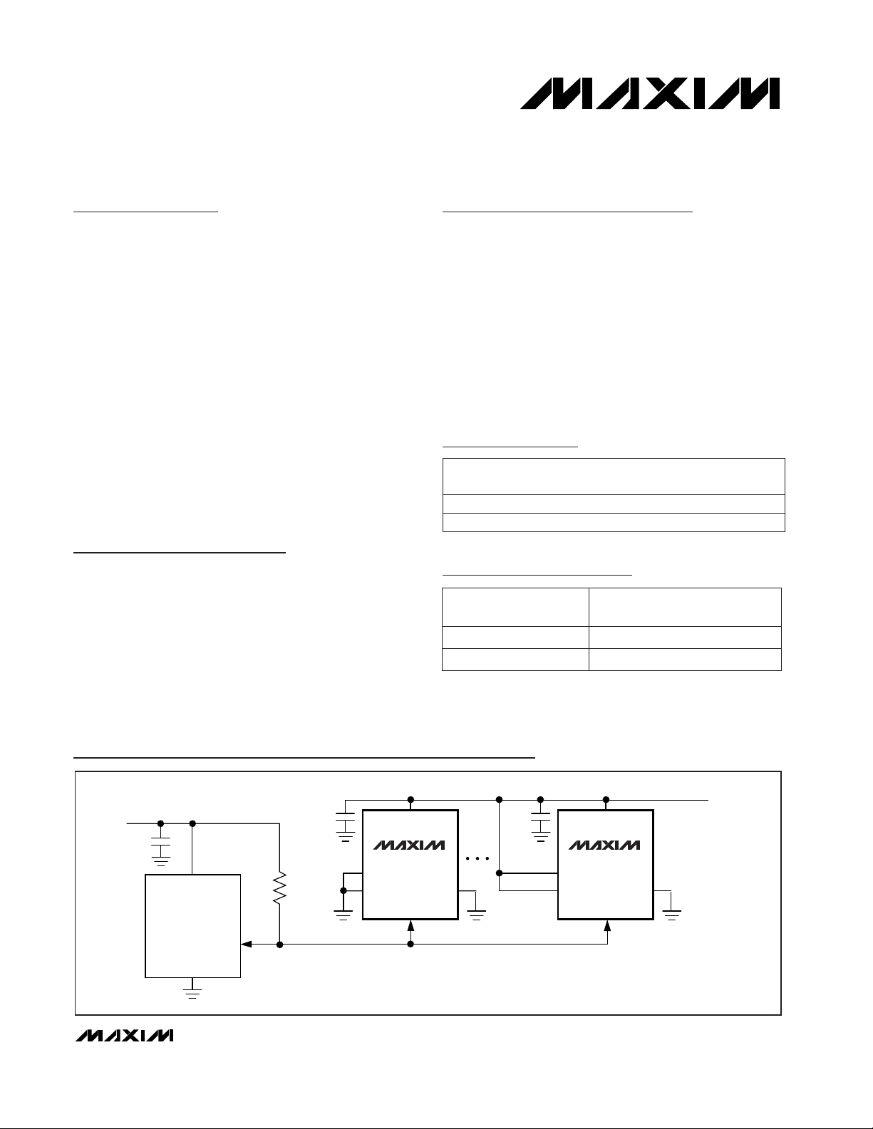
GND
TS0
TS1
I/O
0.1µF
0.1µF
V
DD
MAX6575L
CHIP #1 CHIP #8
10k
+2.7V TO +5.5V
GND
TS0
TS1
I/O
0.1µF
V
DD
MAX6575H
µP
I/O
GND
V
CC
V
CC
Typical Operating Circuit
Page 2
MAX6575L/H
SOT Temperature Sensor with
Multidrop Single-Wire Digital Interface
2 _______________________________________________________________________________________
ABSOLUTE MAXIMUM RATINGS
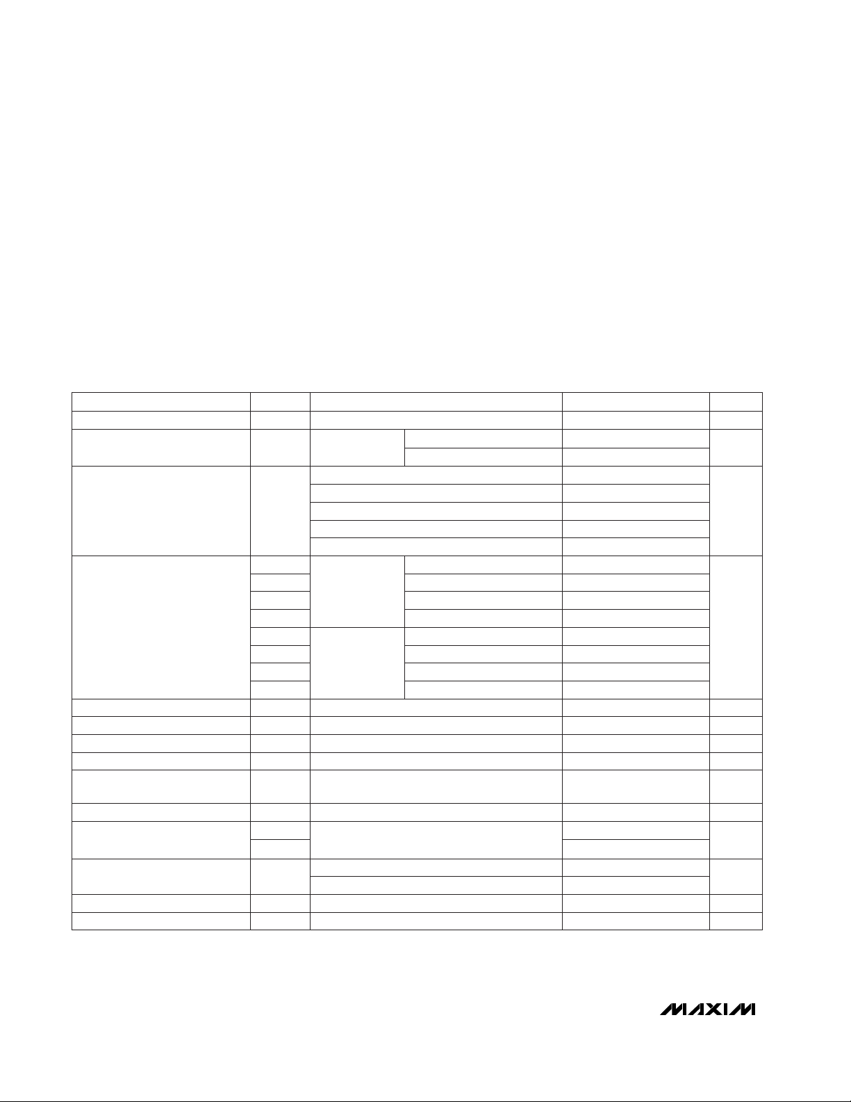
ELECTRICAL CHARACTERISTICS
(VDD= +2.7V to +5.5V, TA= -40°C to +125°C, unless otherwise noted. Typical values are specified at TA= +25°C and VDD= +5V,
unless otherwise noted.)
Stresses beyond those listed under “Absolute Maximum Ratings” may cause permanent damage to the device. These are stress ratings only, and functional
operation of the device at these or any other conditions beyond those indicated in the operational sections of the specifications is not implied. Exposure to
absolute maximum rating conditions for extended periods may affect device reliability.
Note 1: See Temperature Accuracy histograms in
Typical Operating Characteristics
.
Note 2: Guaranteed by design. Not production tested.
Note 3: Limit maximum start pulse at 1ms to avoid timing overlap.
Note 4: If no reset pulse is applied.
Terminal Voltage (with respect to GND)
V
DD
........................................................................-0.3V to +6V
TS1, TS0..................................................-0.3V to (V
DD
+ 0.3V)
I/O..........................................................................-0.3V to +6V
Input/Output Current, All Pins...........................................±20mA
Continuous Power Dissipation (T
A
= +70°C)
6-Pin SOT23 (derate 7.10mW/°C above +70°C)...........571mW
Operating Temperature Range .........................-40°C to +125°C
Storage Temperature Range.............................-65°C to +150°C
Lead Temperature (soldering, 10sec).............................+300°C
VDD= 5.5V
VDD> 2.7V, I
SINK
= 1.2mA
VDD> 4.5V, I
SINK
= 3.2mA
Figure 1
Figure 1
Figure 1
Figure 1, TA= +25°C
CONDITIONS
V2.3V
IH
I/O Input Voltage High
V0.8V
IL
I/O Input Voltage Low
V
0.3
V
OL
I/O Output Voltage Low
0.4
2.3V
IH
Time-Select Pin Logic Levels V
0.8V
IL
ns500Glitch Immunity on I/O Input
ms520t
READY
Delay Time from Trigger to
Ready (Note 4)
µs2.5t
START
Start Pulse (Note 3)
-7.5 ±1.1 +7.5
µA
150 250
I
DD
V2.7 5.5V
DD
VDDRange
Supply Current
µs10t
SETUP
Setup Time
µs5Tt
L1-8
Output Pulse Low Time
5Tt
D1
°C
Temperature Sensor Error
(Note 1)
-5.5 ±0.9 +5.5
-3.0 ±0.8 +3.0
-4.5 ±0.5 +4.5
-5.0 ±0.5 +5.0
UNITSMIN TYP MAXSYMBOLPARAMETER
TA= -20°C
TA= 0°C
TA= +25°C
TA= +85°C
TA= +125°C
Figure 1 ms4.6 16.0t
RESET
Reset Pulse Width (Note 2)
V
TS1
= GND, V
TS0
= GND
V
TS1
= GND, V
TS0
= V
DD
20Tt
D2
V
TS1
= VDD, V
TS0
= GND
MAX6575L,
T (temp) in °K,
Figure 1
40Tt
D3
Output Pulse Delay
V
TS1
= VDD, V
TS0
= V
DD
80Tt
D4
V
TS1
= GND, V
TS0
= GND 160Tt
D5
V
TS1
= GND, V
TS0
= V
DD
320Tt
D6
V
TS1
= VDD, V
TS0
= GND
MAX6575H,
T (temp) in °K,
Figure 1
480Tt
D7
V
TS1
= VDD, V
TS0
= V
DD
µs
640Tt
D8
TA= -40°C to +85°C
TA= -40°C to +125°C 400
Page 3
MAX6575L/H
SOT Temperature Sensor with
Multidrop Single-Wire Digital Interface
_______________________________________________________________________________________
3
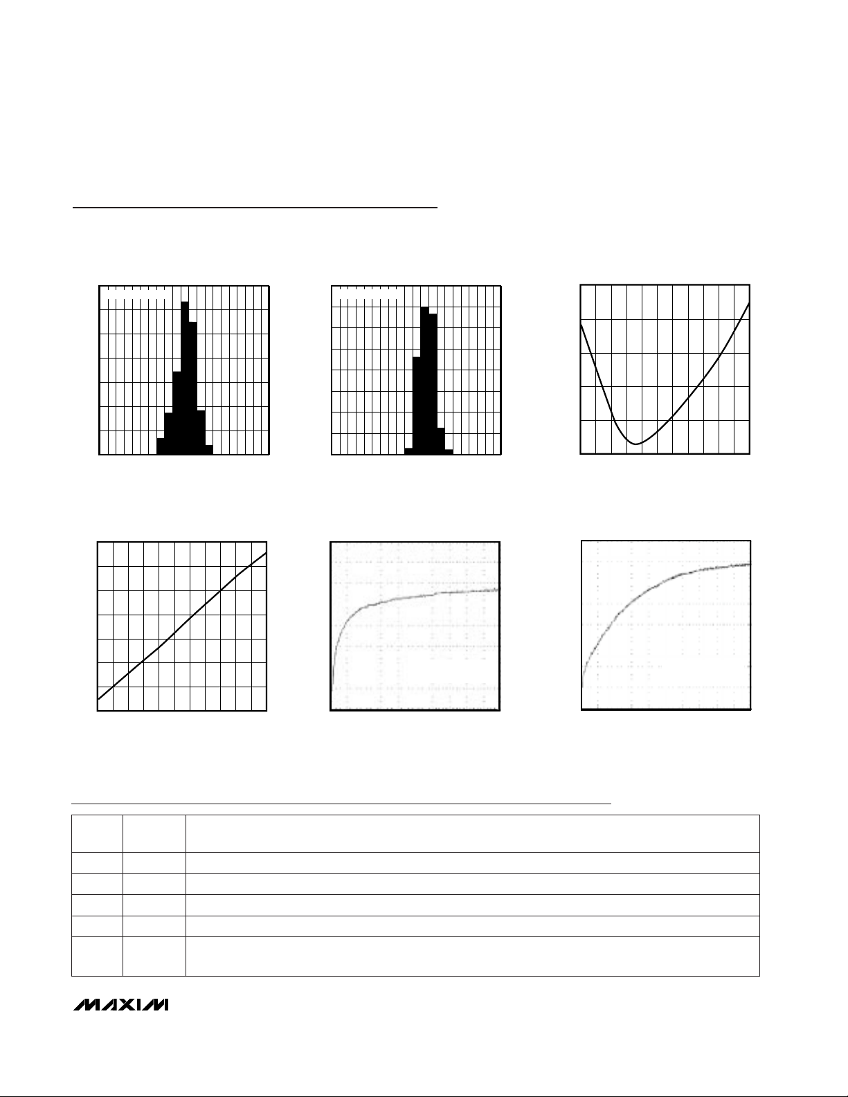
0
10
5
15
20
25
30
35
-5 -3 -2-4 -1012345
TEMPERATURE ACCURACY
(T
A
= +25°C)
MAX6575 toc01
ACCURACY (°C)
PERCENTAGE OF PARTS SAMPLED (%)
SAMPLE SIZE = 200
0
15
10
5
20
25
30
35
40
-5 -3 -2-4 -1 0 1 2 3 4 5
TEMPERATURE ACCURACY
(T
A
= +85°C)
MAX6575 toc02
ACCURACY (°C)
PERCENTAGE OF PARTS SAMPLED (%)
SAMPLE SIZE = 200
-1.0
-0.5
0
0.5
1.0
1.5
-40 -10 5-25 20 35 50 65 80 95 110 125
ACCURACY vs. TEMPERATURE
MAX6576 toc3a
TEMPERATURE (°C)
ACCURACY (°C)
120
140
130
160
150
180
170
190
-40 -10 5 20-25 35 50 65 80 95 110 125
SUPPLY CURRENT vs. TEMPERATURE
MAX6575L/H-03
TEMPERATURE (°C)
SUPPLY CURRENT (µA)
+15°C/div
+100°C
+25°C
THERMAL STEP RESPONSE
IN PERFLUORINATED FLUID
MAX6575L/H-04
5sec/div
MOUNTED ON 0.75 in.
2
OF 2oz. COPPER
+12.5°C/div
+100°C
+25°C
THERMAL STEP RESPONSE
IN STILL AIR
MAX6575L/H-05
20sec/div
MOUNTED ON 0.75 in.
2
OF 2oz. COPPER
Typical Operating Characteristics
(VDD= +5V, TA = +25°C, unless otherwise noted.)
Pin Description
Bidirectional Interface Pin. A time delay between when the part is initiated externally by pulling I/O low and
when the part subsequently pulls I/O low, is proportional to absolute temperature (°K).
I/O6
Time-Select Pins. Set the time delay factor by connecting TS1 and TS0 to either VDDor GND. See Table 1.TS0, TS14, 5
No Connect. Connect pin to GND or leave open.N.C.3
GroundGND2
FUNCTIONPIN NAME
Positive Supply VoltageV
DD
1
Page 4
MAX6575L/H
SOT Temperature Sensor with
Multidrop Single-Wire Digital Interface
4 _______________________________________________________________________________________
_______________Detailed Description
The MAX6575L/H low-cost, low-current (150µA typ)
temperature sensor is ideal for interfacing with microcontrollers or microprocessors. The MAX6575L/H is a
monostable, externally triggered temperature sensor
that uses a Temp→Delay conversion to communicate
with a µP over a single I/O line. Time-select pins (TS1,
TS0) permit the internal temperature-controlled oscillator (TCO) to be scaled by four preset timeout multipliers, allowing eight separate temperature sensors to
share one I/O line. Different sensors on the same I/O
line will use different timeout multipliers to avoid overlapping signals.
Operating the MAX6575L/H
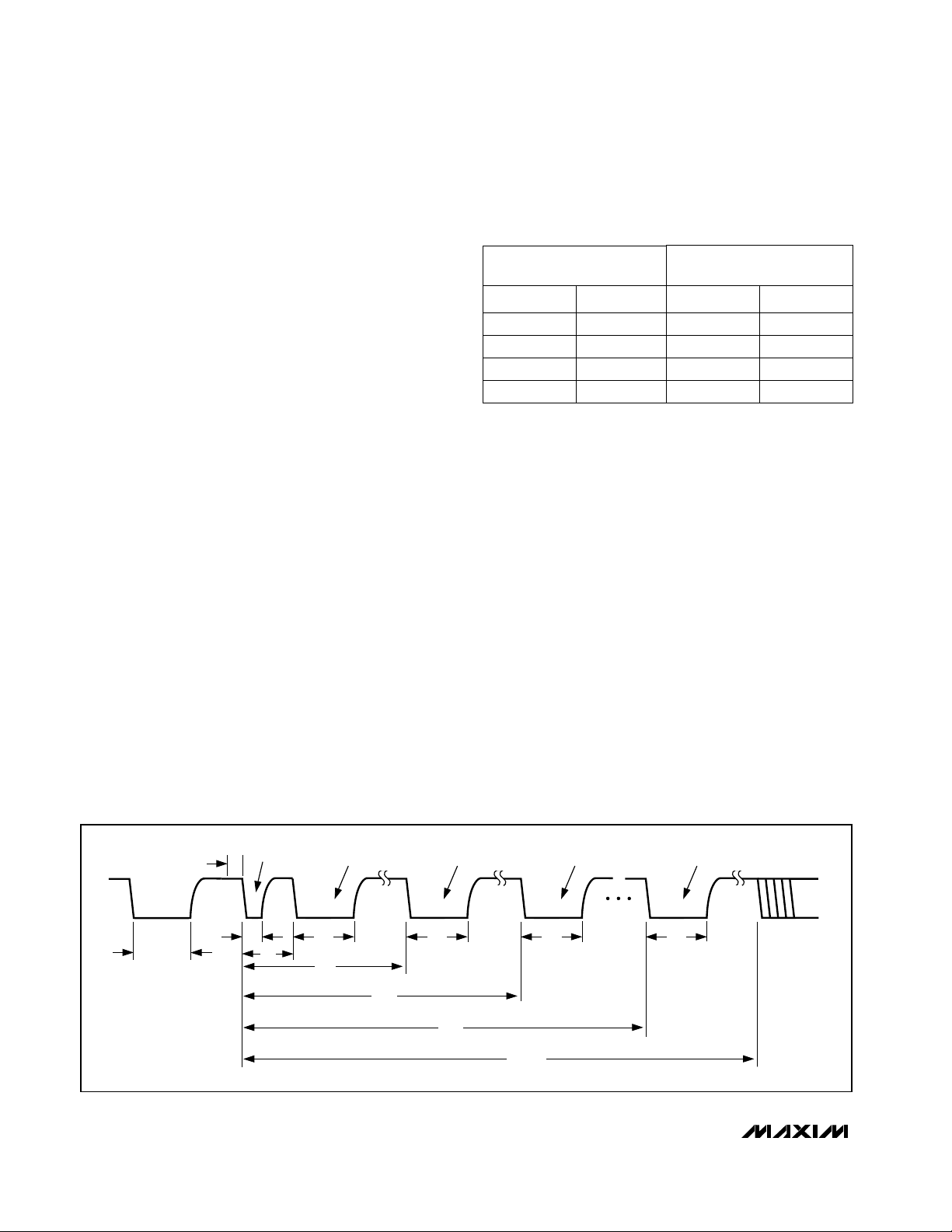
Figure 1 illustrates the timing for the MAX6575L/H.
When the device is powered up, it assumes a ready
state where it awaits an external trigger at the I/O pin.
The I/O pin of the MAX6575L/H has an open-drain output structure that requires a pull-up resistor to maintain
the proper logic levels. Once the I/O pin is pulled low
and then released, control of the I/O pin is transferred
to the MAX6575L/H. The temperature conversion
begins on the falling edge of the externally triggered
pulse. The I/O line is pulled low at a later time. That time
is determined by the device temperature and the Time
Select pins (TS1, TS0). The I/O line remains low for
5Tµs, where T is the temperature in degrees Kelvin. The
temperature of the device is represented by the edgeto-edge delay of the externally triggered pulse and the
falling edge of the subsequent pulse originating from
the device. The device can be manually reset by
pulling the I/O line low for more than t
RESET
(16ms
max). The device will automatically reset after a maxi-
mum delay of 520ms, at which point it will again be in a
ready state awaiting a start pulse.
Definition of Terms:
t
RESET
: Time I/O must be externally pulled low to guar-
antee the MAX6575L/H is in a ready state
awaiting external trigger. (Part will assume a
ready state after 520ms without a reset pulse.)
t
SETUP
: Time I/O must be high prior to a start pulse.
t
START
: Trigger pulse which starts the on-chip timing
sequence on its falling edge.
tDx: Timing delay between the falling edge of the
start pulse and the falling edge initiated by
CHIP#x.
tLx: I/O pulse low time (5Tµs).
t
READY
: Time after falling edge of start pulse when the
MAX6575L/H will reset itself and await the next
external trigger.
The temperature, in degrees Celsius, may be calculat-
ed as follows:
T(°C) = [tDx(µs) / timeout multiplier(µs/°K)] - 273.15°K
GND 5GND
GND 20V
DD
V
DD
40GND
TIME-SELECT PINS
TS0TS1 MAX6575L
160
MAX6575H
320
480
V
DD
80 640V
DD
Figure 1. Timing Diagram
Table 1. Time-Select Pin Configuration
TIMEOUT MULTIPLIERS
(µs/°K)
t
L1
t
D2
CHIP# 1
RESPONSE
t
D3
APPLIED START
t
SETUP
t
t
START
RESET
PULSE
t
D1
t
L2
CHIP# 2
RESPONSE
t
D4
t
READY
t
L3
CHIP# 3
RESPONSE
t
L4
CHIP# 4
RESPONSE
Page 5

Time-Select Pins (TS1, TS0)
Table 1 shows the configuration of the Time-select pins
for the MAX6575L/H. Each device allows four selectable timeout multipliers intended to prevent overlapping when multiple devices are used on the same I/O
line. Tie TS1 and TS0 to either GND or VDDto select the
desired temperature multiplier.
To monitor several chips on the same I/O line, different
timeout multipliers should be selected using the TS1
and TS0 pins. The timeout periods are then scaled so
that the response times will not overlap (see
Timeout
Selection
).
Applications Information
Timeout Selection
Under extreme temperature conditions, it is possible for
an overlap to occur between the timeout delays of different sensors in a multidrop configuration. This overlap
can occur only if the temperature differential recorded
between two devices is very large. Timeout overlaps
can be avoided in multidrop configurations by selecting
the appropriate timeout multipliers. Table 2 illustrates
the allowable temperature differential between devices
when the maximum error is present on each device.
Allowable temperature differentials greater than 165°C
indicate no overlap.
For example, if the maximum temperature differential in
a system is 80°C, the only combinations of timeout multipliers that could result in timeout overlap would be a
320:480µs/°K (70.2°C) or a 480:640µs/°K (37.9°C) combination. As long as these combinations of timeout multipliers are not used in the same multidrop configuration,
no overlap can occur. Thus, seven MAX6575L/H parts
can be used in the same multidrop configuration if the
maximum temperature differential between parts is
80°C. A similar analysis shows that four MAX6575L/H
parts can be used when the maximum temperature differential extends over the entire 165°C range of the part.
Noise Considerations
The accuracy of the MAX6575L/H timeout delay is susceptible to noise generated both internally and externally. The effects of external noise can be minimized by
placing a 0.1µF ceramic bypass capacitor close to the
device’s supply pin. Internal noise is inherent in the
operation of the device and is detailed in Table 3.
Internal averaging minimizes the effect of this noise when
using longer timeout multipliers. The effects of this noise
are included in the overall accuracy of the device as
specified in the
Electrical Characteristics
table.
MAX6575L/H
SOT Temperature Sensor with
Multidrop Single-Wire Digital Interface
_______________________________________________________________________________________ 5
Table 2. Allowable Temperature Differential (°C)
37.9
>16570.2
>165>165>165
>165>165>165153.5
>165>165>165>165132.0
>165>165>165>165>16595.5
640
>165
MAX6575H
480320
>165>165
16080
>165>165
MAX6575L
4020
>165>165
5
TIMEOUT
MULTIPLIER
5
20
40
80
160
320
480
640
Table 3. Typical Peak Noise Amplitude
6404803201608040205
Noise
Amplitude
(°C)
±0.037±0.043±0.063±0.091±0.098±0.15±0.15±0.33
Timeout
Multiplier
MAX6575HMAX6575LPARAMETER
Page 6

MAX6575L/H
Interfacing Multiple Devices
with a Microcontroller
Figure 2 shows how to interface multiple MAX6575L/H
devices with an 8051 microcontroller. The first device,
T1, is configured for a timeout multiplier of 40µs/°K,
while the second device, T2, is configured for a timeout
multiplier of 80µs/°K to avoid overlap. The microcontroller takes in temperature values from both sensors,
T1 and T2, on a single port pin, P3.7. The microcontroller displays five times the temperature in degrees
Celsius in binary on Port 1. A switch connected to a
pull-up resistor at Port 3.5 selects which temperature is
displayed: open = T1, closed = T2. Code is provided
for this application as Listing 1.
SOT Temperature Sensor with
Multidrop Single-Wire Digital Interface
6 _______________________________________________________________________________________
GND
TS0
TS1
I/O I/O
0.1µF
V
DD
V
DD
MAX6575L MAX6575L
+2.7V TO +5.5V +2.7V TO +5.5V
GND
X2
X1
P3.7
P3.5
10k
OPEN: T1
CLOSED: T2
470Ω (8)
V
CC
V
CC
10k
P1.1
P1.2
P1.3
P1.4
P1.5
P1.6
P1.7
8051
12MHz
22pF
22pF
GND
T2T1
TS0
80µs/°K40µs/°K
TS1
0.1µF
P1.0
Figure 2. Interfacing Multiple Devices with a Microcontroller
Page 7

MAX6575L/H
SOT Temperature Sensor with
Multidrop Single-Wire Digital Interface
_______________________________________________________________________________________ 7
Listing 1. 8051 Code Example
Page 8

MAX6575L/H
SOT Temperature Sensor with
Multidrop Single-Wire Digital Interface
8 _______________________________________________________________________________________
Listing 1. 8051 Code Example (continued)
Page 9

MAX6575L/H
SOT Temperature Sensor with
Multidrop Single-Wire Digital Interface
_______________________________________________________________________________________ 9
Listing 1. 8051 Code Example (continued)
Chip Information
TRANSISTOR COUNT: 302
Pin Configuration
GND
TS0N.C.
16I/O
5 TS1
V
DD
MAX6575L
MAX6575H
SOT23-6
TOP VIEW
2
34
Page 10

MAX6575L/H
SOT Temperature Sensor with
Multidrop Single-Wire Digital Interface
10 ______________________________________________________________________________________
Package Information
6LSOT.EPS
Page 11

MAX6575L/H
SOT Temperature Sensor with
Multidrop Single-Wire Digital Interface
______________________________________________________________________________________ 11
NOTES
Page 12

MAX6575L/H
SOT Temperature Sensor with
Multidrop Single-Wire Digital Interface
Maxim cannot assume responsibility for use of any circuitry other than circuitry entirely embodied in a Maxim product. No circuit patent licenses are
implied. Maxim reserves the right to change the circuitry and specifications without notice at any time.
12
____________________Maxim Integrated Products, 120 San Gabriel Drive, Sunnyvale, CA 94086 408-737-7600
© 1999 Maxim Integrated Products Printed USA is a registered trademark of Maxim Integrated Products.
NOTES
 Loading...