

Page 1
General Description
The MAX5406 stereo audio processor provides a complete audio solution with volume, balance, bass, and
treble controls. It features dual 32-tap logarithmic
potentiometers for volume control, dual potentiometers
for balance control, and linear digital potentiometers for
tone control. A simple debounced pushbutton interface
controls all functions. The MAX5406 advances the
wiper setting once per button push. Maxim’s proprietary SmartWiper™ control eliminates the need for a
microcontroller (µC) to increase the wiper transition
rate. Holding the control input low for more than 1s
advances the wiper at a rate of 4Hz for 4s and 16Hz
thereafter. An integrated click/pop suppression feature
eliminates the audible noise generated by the wiper’s
movements.
The MAX5406 provides a subwoofer output that internally combines the left and right channels. An external
filter capacitor allows for a customized cut-off frequency for the subwoofer output. A bass-boost mode
enhances the low-frequency response of the left and
right channels. An integrated bias amplifier generates
the required (VDD+ VSS) / 2 bias voltage, eliminating
the need for external op amps for unipolar operation.
The MAX5406 also features ambience control to
enhance the separation of the left- and right-channel
outputs for headphones and desktop speakers systems, and a pseudostereo feature that approximates
stereo sound from a monophonic signal.
The MAX5406 is available in a 7mm x 7mm, 48-pin
TQFN package and in a 48-pin TSSOP package and is
specified over the extended (-40°C to +85°C) temperature range.
Applications
Automotive Rear-Seat Entertainment (RSE)
Desktop Speakers
Portable Audio
PDAs or MP3 Player Docking Stations
Karaoke Machines
Flat-Screen TVs
Features
♦ Audio Processor Including All Op Amps and Pots
for Volume, Balance, Mute, Bass, Treble,
Ambience, Pseudostereo, and Subwoofer
♦ 32-Tap Volume Control (2dB Steps)
♦ Small, 7mm x 7mm, 48-Pin TQFN and 48-Pin
TSSOP Packages
♦ Single +2.7V to +5.5V or Dual ±2.7V Supply
Operation
♦ Clickless Switching and Control
♦ Mute Function to < -90dB (typ)
♦ Channel Isolation > -70dB (typ)
♦ Two Sets of Single-Ended or Differential Stereo
Inputs Can Be Used for Summing/Mixing
♦ Debounced Pushbutton Interface Works with
Momentary Contact Switches or Microprocessors
(µPs)
♦ Low 0.2µA (typ) Shutdown Supply Current
♦ Shutdown Stores All Control Settings
♦ 0.02% (typ) THD into 10kΩ Load, 25µV
RMS
(typ)
Output Noise
♦ Internally Generated 1/2 Full-Scale Bias Voltage
for Single-Ended Applications
♦ Power-On Volume Setting to -20dB
♦ Internal Passive RF Filters for Analog Inputs
Prevent High Frequencies from Reaching the
Speakers
MAX5406
Audio Processor with Pushbutton Interface
________________________________________________________________ Maxim Integrated Products 1
19-3817; Rev 0; 5/06
For pricing, delivery, and ordering information, please contact Maxim/Dallas Direct! at
1-888-629-4642, or visit Maxim’s website at www.maxim-ic.com.
Ordering Information
PART
TEMP RANGE
PIN-
PKG
CODE
MAX5406EUM
48 TSSOP U48-1
MAX5406ETM*
48 TQFN T4877-6
SmartWiper is a trademark of Maxim Integrated Products, Inc.
*Future product—contact factory for availability.
Pin Configurations appear at end of data sheet.
PACKAGE
-40°C to +85°C
-40°C to +85°C
Page 2
MAX5406
Audio Processor with Pushbutton Interface
2 _______________________________________________________________________________________
ABSOLUTE MAXIMUM RATINGS
Stresses beyond those listed under “Absolute Maximum Ratings” may cause permanent damage to the device. These are stress ratings only, and functional
operation of the device at these or any other conditions beyond those indicated in the operational sections of the specifications is not implied. Exposure to
absolute maximum rating conditions for extended periods may affect device reliability.
L1_H, L1_L, L2_H, L2_L
to V
SS
.......................-0.3V to the lower of (VDD+ 0.3V) or +6V
R1_H, R1_L, R2_H, R2_L
to V
SS
.......................-0.3V to the lower of (VDD+ 0.3V) or +6V
AMB, BALL, BALR, VOLUP, VOLDN, MUTE, SHDN, BASSDN,
BASSUP, TREBDN, TREBUP
to DGND .............-0.3V to the lower of (V
LOGIC
+ 0.3V) or +6V
CTL_, CTR_, CBL_, CBR_, CLS_, CRS_, CSUB, CBIAS, CMSNS,
AMBLI, AMBRI, BIAS
to V
SS
.......................-0.3V to the lower of (VDD+ 0.3V) or +6V
LOUT, ROUT, SUBOUT, LMR,
LPR to V
SS
................-0.3V to the lower of (VDD+ 0.3V) or +6V
V
DD
to VSS................................................................-0.3V to +6V
V
DD
to V
LOGIC
........................................................................±6V
V
LOGIC
to DGND ......................................................-0.3V to +6V
DGND to V
SS
............................................................-0.3V to +6V
LOUT, ROUT, SUBOUT Short Circuited to V
SS
.........Continuous
Continuous Power Dissipation (T
A
= +70°C)
48-Pin TQFN (derate 27.8mW/°C above +70°C) ........2222mW
48-Pin TSSOP (derate 16mW/°C above +70°C) .........1282mW
Operating Temperature Range ...........................-40°C to +85°C
Junction Temperature......................................................+150°C
Storage Temperature Range .............................-60°C to +150°C
Lead Temperature (soldering, 10s) .................................+300°C
ELECTRICAL CHARACTERISTICS
(VDD= V
LOGIC
= +5.0V, VSS= 0, V
BIAS
= V
CMSNS
= V
DD
/ 2, DGND = 0, ambience disabled, V
AMBLI
= V
AMBRI
= V
BIAS, VR1_L
=
V
L1_L
= V
R2_L
= V
L2_L
= external V
BIAS
, C
CSUB
= 0.15µF, C
CLS
= C
CRS
= 1µF, C
CBL
= C
CBR
= 3.3nF, C
CTL
= C
CTR
= 4.7nF, C
BIAS
=
0.1µF, C
CBIAS
= 50µF (see the Typical Application Circuit), TA= T
MIN
to T
MAX
unless otherwise specified. Typical values are at TA=
+25°C). (Note1)
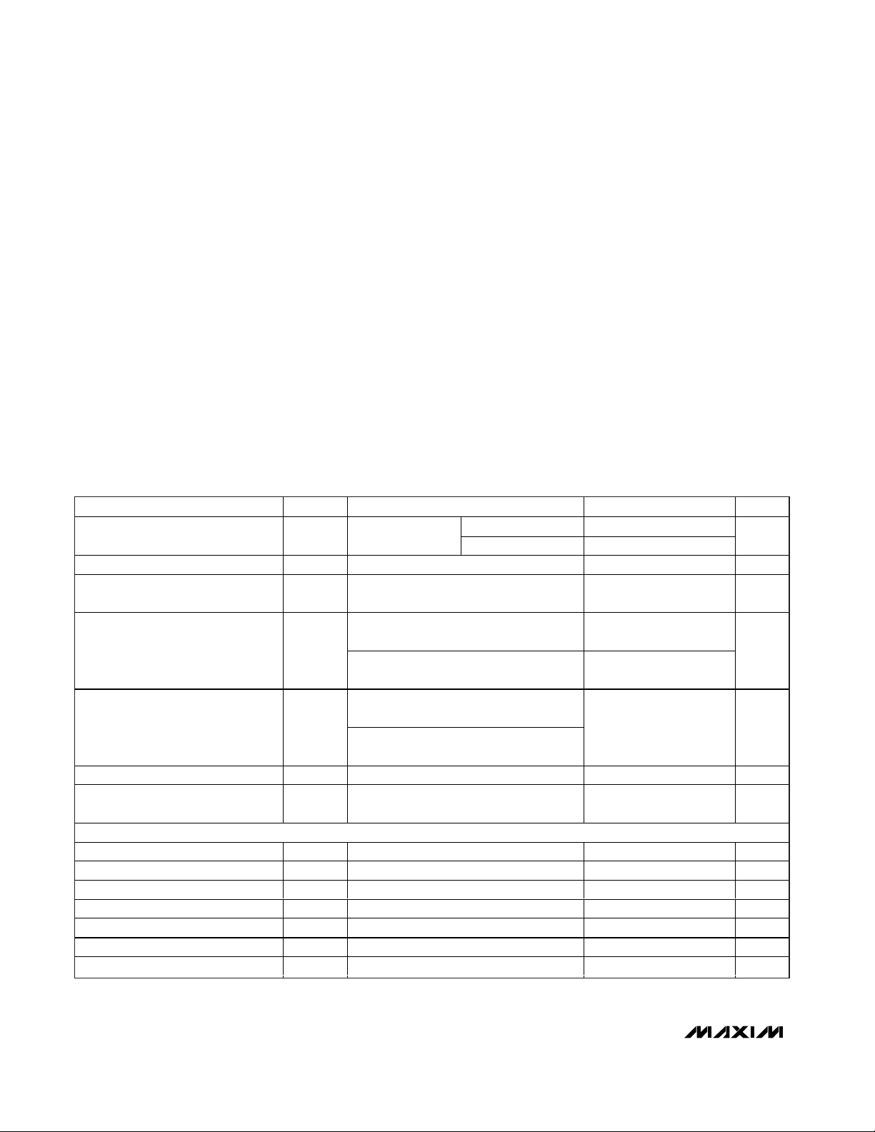
PARAMETER
SYMBOL
CONDITIONS
UNITS
R
INH
810
Signal-Inputs Input Resistance R
IN
With respect to
V
BIAS
R
INL
16 20
kΩ
Signal-Inputs Input Capacitance C
IN
With respect to V
BIAS
5pF
RF Rejection
2MHz to 2.4GHz two-tone test, 2/2.01MHz
input to 10kHz out
20 dBc
VDD = +5V, VSS = 0, VCM = V
BIAS
, gain
error ≤ -0.5dB
-4 +4
Differential Input Voltage Range V
IN
VDD = +2.7V, VSS = -2.7V, VCM = V
BIAS
,
gain error ≤ -0.5dB
V
VDD = +5V, VSS = 0, V
BIAS
= VDD / 2,
V
DIFF
= 100mV
Common-Mode Input Voltage Range
V
CM
VDD = +2.7V, VSS = -2.7V, V
BIAS
= 0,
V
DIFF
= 100mV
V
Bias Voltage V
BIAS
Internally generated (V
CMSNS
= VSS)(V
DD
+ VSS) / 2 V
Bias-Voltage Input Current
L_ _H
=
R_ _H
=
V
BIAS,
L_ _L = R_ _L =
open, V
CMSNS = VDD
1mA
AUDIO PROCESSING FUNCTIONS
Maximum Balance Difference (Note 2) 10 12 14 dB
Minimum Balance Difference (Note 2) 0 dB
Balance Resolution (Note 2) 2 dB
Maximum Volume Attenuation (Note 2) -63 -62 -59 dB
Minimum Volume Attenuation (Note 2)
0
dB
Volume Resolution (Note 2) 2 dB
Volume-Control Steps (Note 2) 32
steps
MIN TYP MAX
-4.5 +4.5
VSS + 0.5V VDD - 0.5V
-0.5
+0.5
Page 3
MAX5406
Audio Processor with Pushbutton Interface
_______________________________________________________________________________________ 3
ELECTRICAL CHARACTERISTICS (continued)
(VDD= V
LOGIC
= +5.0V, VSS= 0, V
BIAS
= V
CMSNS
= V
DD
/ 2, DGND = 0, ambience disabled, V
AMBLI
= V
AMBRI
= V
BIAS, VR1_L
=
V
L1_L
= V
R2_L
= V
L2_L
= external V
BIAS
, C
CSUB
= 0.15µF, C
CLS
= C
CRS
= 1µF, C
CBL
= C
CBR
= 3.3nF, C
CTL
= C
CTR
= 4.7nF, C
BIAS
=
0.1µF, C
CBIAS
= 50µF (see the Typical Application Circuit), TA= T
MIN
to T
MAX
unless otherwise specified. Typical values are at TA=
+25°C). (Note1)
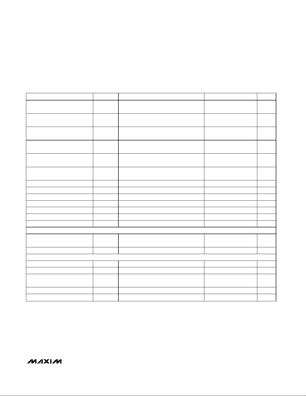
PARAMETER
SYMBOL
CONDITIONS
MIN
TYP
MAX
UNITS
Gain Matching of Input 1 to Input
2 of Each Channel
Volume = 0dB (Note 2)
dB
Gai n M atchi ng of Left to Ri g ht
C hannel
Volume = 0dB (Note 2)
dB
Bass-Boost Range
f
BASS
= 1kHz, treble = 0dB,
C
CB_
= open, C
CT_
= open (Note 3)
10 14 dB
Bass-Cut Range
f
BASS
= 1kHz, treble = 0dB,
C
CB_
= open, C
CT_
= open (Note 3)
10 14 dB
Treble-Boost Range
f
TREBLE
= 1kHz, bass = 0dB,
C
CB_
= open, C
CT_
= short (Note 3)
10 15 dB
Treble-Cut Range
f
TREBLE
= 1kHz, bass = 0dB,
C
CB_
= open, C
CT_
= short (Note 3)
10 15 dB
Bass-Boost/-Cut Steps Max boost to max cut 21
steps
Treble-Boost/-Cut Steps Max boost to max cut 21
steps
Bass End-to-End Resistance R
BPOT
kΩ
Treble End-to-End Resistance R
TPOT
17 kΩ
Bass Series Resistance R
B
40 kΩ
Treble Series Resistance R
T
3.5 kΩ
Mute Attenuation -90 dB
AC PERFORMANCE (VIN = 1V
P-P
, RL = 10kΩ, VDD = +2.7V, VSS = -2.7V, volume = 0dB, treble = bass = 0dB)
Total H ar m oni c D i stor ti on P l us
N oi se
THD+N (Notes 4, 5)
%
Interchannel Crosstalk L to R or R to L -70 dB
ROUT/LOUT OUTPUTS
Maximum Load Capacitance C
LOAD
pF
Output-Voltage Swing
RL = 10kΩ, VDD = +2.7V, VSS = -2.7V
V
Output Offset Voltage V
OOS
VDD = +2.7V, VSS = -2.7V, volume = 0dB,
R
L
= 10kΩ, inputs = V
BIAS
-30 0
mV
Short-Circuit Output Current I
SC
Shorted to V
SS
15 mA
Output Resistance R
_OUTILOAD
= 100µA to 500µA 10 Ω
V
OUTP-P
-0.1 +0.1
-0.1 +0.1
-2.3 +2.3
116
0.02 0.05
100
+30
Page 4
MAX5406
Audio Processor with Pushbutton Interface
4 _______________________________________________________________________________________
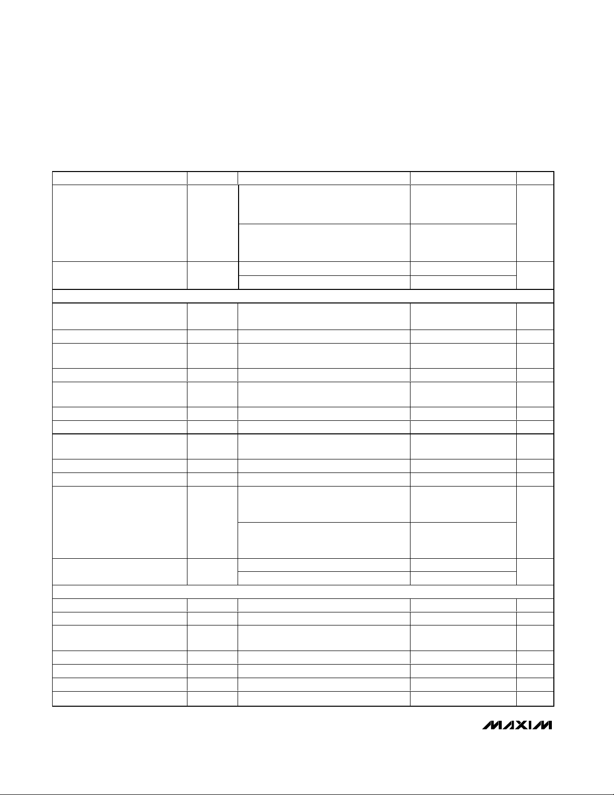
PARAMETER
SYMBOL
CONDITIONS
MIN
TYP
MAX
UNITS
fBW = 20Hz to 20kHz, VIN = V
BIAS
,
mute on, noise measured at LOUT and
ROUT (Notes 2, 4, 5)
3.5 9.5
Output Noise e
n
fBW = 20Hz to 20kHz, VIN = V
BIAS
, mute
off, volume = 0dB, noise measured at
LOUT and ROUT (Notes 2, 4, 5)
25 35
µV
RMS
100mV
P-P
at 217Hz on V
DD
-70
Power-Supply Rejection Ratio PSRR
100mV
P-P
at 1kHz on V
DD
-65
dB
SUBWOOFER OUTPUT
Gain
(V
L1_H
- V
L1_L
) to (V
SUBOUT
- V
BIAS
),
volume = 0dB (Note 2)
-6 dB
Highpass Filter Cutoff Frequency
Volume = 0dB 15 Hz
Internal Highpass Cutoff
Resistance
R
_S
Figure 12
kΩ
Lowpass Filter Cutoff Frequency
Volume = 0dB
Hz
Internal Lowpass Cutoff
Resistance
R
SUB
Figure 12
kΩ
Maximum Load Capacitance
pF
Output-Voltage Swing
RL = 10kΩ, VDD = +2.7V, VSS = -2.7V
V
Output Offset Voltage
VDD = +2.7V, VSS = -2.7V, volume = 0dB,
R
L
= 10kΩ
-15 0
mV
Short-Circuit Output Current I
SUBSC
Shorted to V
SS
12 mA
Output Resistance
I
LOAD
= 100µA to 500µA 10 Ω
fBW = 20Hz to 20kHz, VIN = V
BIAS
,
mute on, noise measured at SUBOUT
(Notes 2, 4, 5)
911
Output Noise e
n
fBW = 20Hz to 20kHz, VIN = V
BIAS
,
volume = 0dB, mute off, noise measured at
SUBOUT (Notes 2, 4, 5)
25 35
µV
RMS
100mV
P-P
at 217Hz on V
DD
-70
Power-Supply Rejection Ratio PSRR
100mV
P-P
at 1kHz on V
DD
-65
dB
PUSHBUTTON CONTACT INPUTS (MUTE, AMB, VOLUP, VOLDN, BALL, BALR, BASSUP, BASSDN, TREBUP, TREBDN)
Internal Pullup Resistor R
PU
50 kΩ
Single-Pulse Input Low Time t
LPW
Figures 2a, 11a, 11b 30 ms
Repetitive Input Pulse Separation
Time
t
HPW
Figure 2b, 11a, 11b 40 ms
First Autoincrement Point t
A1
Figure 3 1 s
First Autoincrement Rate f
A1
Figure 3 4 Hz
Second Autoincrement Point t
A2
Figure 3 4 s
Second Autoincrement Rate f
A2
Figure 3 16 Hz
ELECTRICAL CHARACTERISTICS (continued)
(VDD= V
LOGIC
= +5.0V, VSS= 0, V
BIAS
= V
CMSNS
= V
DD
/ 2, DGND = 0, ambience disabled, V
AMBLI
= V
AMBRI
= V
BIAS, VR1_L
=
V
L1_L
= V
R2_L
= V
L2_L
= external V
BIAS
, C
CSUB
= 0.15µF, C
CLS
= C
CRS
= 1µF, C
CBL
= C
CBR
= 3.3nF, C
CTL
= C
CTR
= 4.7nF, C
BIAS
=
0.1µF, C
CBIAS
= 50µF (see the Typical Application Circuit), TA= T
MIN
to T
MAX
unless otherwise specified. Typical values are at TA=
+25°C). (Note1)
13.8
100
10.6
CSUBLOAD 100
V
SUBOUTP-P
V
SUBOOS
-2.3 +2.3
R
SUBOUT
+15
Page 5
MAX5406
Audio Processor with Pushbutton Interface
_______________________________________________________________________________________ 5
PARAMETER
SYMBOL
CONDITIONS
MIN
TYP
MAX
UNITS
DIGITAL INPUTS (V
LOGIC
> 3.6V) (MUTE, AMB, VOLUP, VOLDN, BALL, BALR, BASSUP, BASSDN, TREBUP, TREBDN)
Input-Voltage High V
IH
2.4 V
Input-Voltage Low V
IL
0.8 V
SHDN Input-Voltage High
3.4 V
SHDN Input-Voltage Low
0.8 V
Input Leakage Current ±5 µA
Input Capacitance 5pF
D IG IT A L IN PU T S ( V
L OG IC
≤ 3. 6 V) ( M UT E, A M B , VO L UP, VO L DN , B AL L , B AL R, B ASSU P, B ASSD N, T REBU P, T REBD N)
Input-Voltage High V
IH
2V
Input-Voltage Low V
IL
0.6 V
SHDN Input-Voltage High
2V
SHDN Input-Voltage Low
0.6 V
Input Leakage Current ±5 µA
Input Capacitance 5pF
TIMING CHARACTERISTICS
Wiper Settling Time t
WS
Click/pop suppression inactive, Figures 2a,
11a, 11b
45 ms
POWER SUPPLIES (V
CMSNS
= VSS, internal bias enabled)
Supply-Voltage Difference
V
Positive Analog Supply Voltage V
DD
V
Negative Analog Supply Voltage
V
SS
0V
Dual-Supply Positive Supply
Voltage
V
DD
VSS = -2.7V 0
V
Active Positive Supply Current I
DD
No signal, all logic inputs pulled high to
RL = 10kΩ (Note 6)
10 13 mA
No signal, all logic inputs connected to
DGND or V
LOGIC
, VDD = +5V, VSS = 0
-13 -10
Active Negative Supply Current
(Note 6)
I
SS
No signal, all logic inputs connected to
DGND or V
LOGIC
, VDD = +2.7V,
V
SS
= -2.7V
-13 -10
mA
No signal, VDD = 5V, VSS = 0, all logic
inputs connected to DGND or V
LOGIC
,
SHDN = DGND
0.2
0.2
S hutd ow n S up p l y C ur r ent ( N ote 6)
I
SHDN
No signal, VDD = +2.7V, VSS = -2.7V,
all logic at DGND or V
LOGIC
, SHDN
= DGND
50
µA
ELECTRICAL CHARACTERISTICS (continued)
(VDD= V
LOGIC
= +5.0V, VSS= 0, V
BIAS
= V
CMSNS
= V
DD
/ 2, DGND = 0, ambience disabled, V
AMBLI
= V
AMBRI
= V
BIAS, VR1_L
=
V
L1_L
= V
R2_L
= V
L2_L
= external V
BIAS
, C
CSUB
= 0.15µF, C
CLS
= C
CRS
= 1µF, C
CBL
= C
CBR
= 3.3nF, C
CTL
= C
CTR
= 4.7nF, C
BIAS
=
0.1µF, C
CBIAS
= 50µF (see the Typical Application Circuit), TA= T
MIN
to T
MAX
unless otherwise specified. Typical values are at TA=
+25°C). (Note1)
V
IHSHDN
V
ILSHDN
V
IHSHDN
V
ILSHDN
VDD - V
SS
V
or unconnected, SHDN = V
LOGIC
+2.7 +5.5
+5.5
-2.7
+2.7
,
LOGIC
I
DD
I
SS
Page 6
Typical Operating Characteristics
(TA = +25°C, unless otherwise noted.)
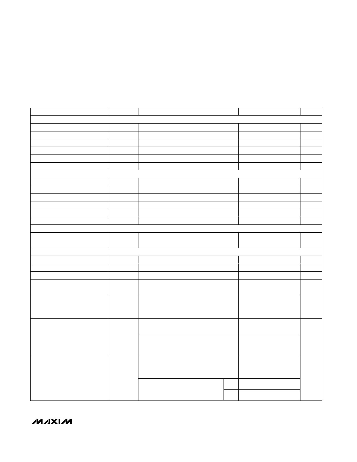
ATTENUATION vs. TAP POSITION
TAP POSITION
ATTENUATION (dB)
MAX5406 toc01a
0 4 8 12 16 20 24 28 32
-70
-60
-50
-40
-30
-20
-10
0
VDD = V
LOGIC
= 5V, VSS = 0
VOLUP = 0dB
ATTENUATION vs. TAP POSITION
TAP POSITION
ATTENUATION (dB)
MAX5406 toc01b
0 4 8 12 16 20 24 28 32
-70
-60
-50
-40
-30
-20
-10
0
VDD = V
LOGIC
= 2.7V, VSS = -2.7V
BAXANDALL CURVE
FREQUENCY (Hz)
GAIN (dB)
MAX5406 toc02a
-15
-10
-5
0
5
10
15
10 100 1000 10,000 100,000
VDD = V
LOGIC
= 5V, VSS = 0
TREBLE = BASS
C
CB_
= 10nF
C
CT_
= 2.2nF
MAX5406
Audio Processor with Pushbutton Interface
6 _______________________________________________________________________________________
Note 1: All devices 100% production tested at TA= +85°C. Limits over the operating temperature range are guaranteed by design.
Note 2: Treble = bass = 0dB. C
CB_
= open, CCT_ = short, left input signal = right input signal = +2V.
Note 3: See Tables 3 and 4 and Figure 7. V
DD
= +2.7V, V
SS
= -2.7V.
Note 4: Guaranteed by design.
Note 5: Measured with A-weighted filter.
Note 6: Supply current measured while attenuator position is fixed.
Note 7: Set _OUT = 0dB and shutdown device SHDN = 0. t
WU
is the time required for _OUT to reach 0dB after SHDN goes high.
PARAMETER
CONDITIONS
UNITS
Power-Up Time t
PU
Power first applied, _OUT = -20dB 1 s
Wake-Up Time t
WU
From shutdown (Note 7) 1 s
Logic Supply Voltage V
LOGIC
DGND = 0, V
LOGIC
≤ V
DD
V
Logic Active Supply Current I
LOGIC
No signal, one button pressed, remaining
logic inputs connected to V
LOGIC
or
unconnected
µA
Logic Shutdown Supply Current
No signal, all logic inputs connected to
V
LOGIC
or unconnected, SHDN = DGND
(Note 6)
0.2 2 µA
ELECTRICAL CHARACTERISTICS (continued)
(VDD= V
LOGIC
= +5.0V, VSS= 0, V
BIAS
= V
CMSNS
= V
DD
/ 2, DGND = 0, ambience disabled, V
AMBLI
= V
AMBRI
= V
BIAS, VR1_L
=
V
L1_L
= V
R2_L
= V
L2_L
= external V
BIAS
, C
CSUB
= 0.15µF, C
CLS
= C
CRS
= 1µF, C
CBL
= C
CBR
= 3.3nF, C
CTL
= C
CTR
= 4.7nF, C
BIAS
=
0.1µF, C
CBIAS
= 50µF (see the Typical Application Circuit), TA= T
MIN
to T
MAX
unless otherwise specified. Typical values are at TA=
+25°C). (Note1)
SYMBOL
MIN TYP MAX
+2.7 V
DD
150
Page 7
MAX5406
Audio Processor with Pushbutton Interface
_______________________________________________________________________________________ 7
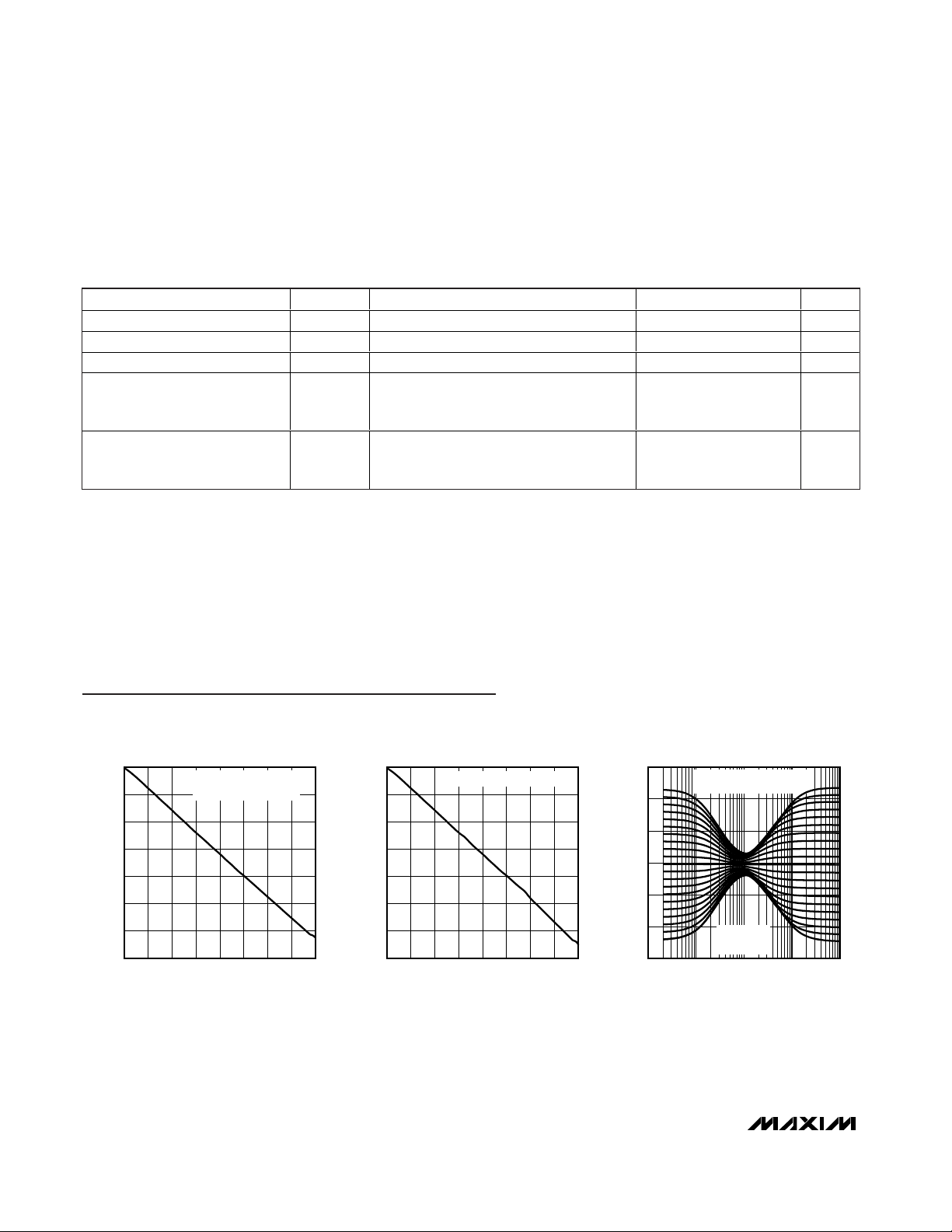
BAXANDALL CURVE
FREQUENCY (Hz)
GAIN (dB)
MAX5406 toc02b
-20
-15
-10
-5
0
5
10
15
20
10 100 1000 10,000 100,000
VDD = V
LOGIC
= 2.7V, VSS = -2.7V
V
IN
= 0.5V
P-P
BASS = TREBLE
C
CB_
= 10nF
C
CT_
= 2.2nF
BAXANDALL CURVE
FREQUENCY (Hz)
GAIN (dB)
MAX5406 toc02c
-20
-15
-10
-5
0
5
10
15
10 100 1000 10,000 100,000
C
CB_
= 10nF
C
CT_
= 2.2nF
V
DD
= V
LOGIC
= 5V, VSS = 0
BASS = 0dB
BAXANDALL CURVE
FREQUENCY (Hz)
GAIN (dB)
MAX5406 toc02d
-20
-15
-10
-5
0
5
10
15
10 100 1000 10,000 100,000
C
CB_
= 10nF
C
CT_
= 2.2nF
V
DD
= V
LOGIC
=2.7V, VSS = -2.7V
V
IN
= 0.5V
P-P
BASS = 0dB
BAXANDALL CURVE
FREQUENCY (Hz)
GAIN (dB)
MAX5406 toc02e
-15
-10
-5
0
5
10
15
10 100 1000 10,000 100,000
C
CB_
= 10nF
C
CT_
= 2.2nF
V
DD
= V
LOGIC
= 5V, VSS = 0
TREBLE = 0dB
BAXANDALL CURVE
FREQUENCY (Hz)
GAIN (dB)
MAX5406 toc02f
-20
-15
-10
-5
0
5
10
15
20
10 100 1000 10,000 100,000
C
CB_
= 10nF
C
CT_
= 2.2nF
V
DD
= V
LOGIC
= 2.7V, VSS = -2.7V
V
IN
= 0.5V
P-P
TREBLE = 0dB
SINGLE-SUPPLY SUBOUT
FREQUENCY RESPONSE
FREQUENCY (Hz)
GAIN (dB)
MAX5406 toc03a
-70
-60
-50
-40
-30
-20
-10
0
10
10 100 1000 10,000 100,000
DUAL INPUTS
Typical Operating Characteristics (continued)
(TA = +25°C, unless otherwise noted.)
DUAL-SUPPLIES SUBOUT
FREQUENCY RESPONSE
FREQUENCY (Hz)
GAIN (dB)
MAX5406 toc03b
-60
-50
-40
-30
-20
-10
0
10
10 100 1000 10,000 100,000
DUAL INPUTS
VDD = V
LOGIC
= 2.7V, VSS = -2.7V
VOLUP = 0dB
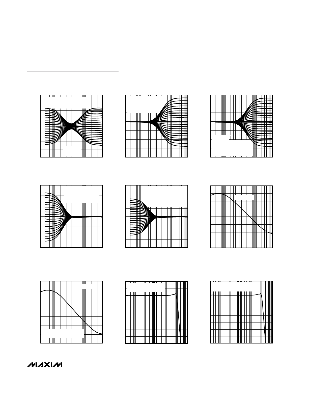
LOUT FREQUENCY RESPONSE
FREQUENCY (Hz)
GAIN (dB)
MAX5406 toc03c
-35
-30
-25
-20
-15
-10
-5
0
5
10
10 100 1k 10k 100k 1M 10M
VDD = V
LOGIC
= 5V, VSS = 0
VOLUP = 0dB
DUAL-SUPPLIES LOUT
FREQUENCY RESPONSE
FREQUENCY (Hz)
GAIN (dB)
MAX5406 toc03d
-35
-30
-25
-20
-15
-10
-5
0
5
10
10 100 1k 10k 100k 1M 10M
VDD = V
LOGIC
= 2.7V, VSS = -2.7V
VOLUP = 0dB
Page 8
MAX5406
Audio Processor with Pushbutton Interface
8 _______________________________________________________________________________________
TOTAL SUPPLY CURRENT
vs. TEMPERATURE (I
DD
+ I
LOGIC
)
TEMPERATURE (°C)
SUPPLY CURRENT (mA)
MAX5406 toc06a
-40 -15 10 35 60 85
8.0
8.5
9.0
9.5
10.0
10.5
11.0
11.5
12.0
VDD = V
LOGIC
= 5V, VSS = 0
INACTIVE MODE, NO BUTTON PUSHED
ACTIVE MODE, ONE BUTTON PUSHED
TOTAL SUPPLY CURRENT
vs. TEMPERATURE (I
DD
+ I
LOGIC
)
TEMPERATURE (°C)
SUPPLY CURRENT (mA)
MAX5406 toc06b
-40 -15 10 35 60 85
5
7
9
11
13
15
VDD = V
LOGIC
= 2.7V, VSS = -2.7V
TOTAL SUPPLY CURRENT: I
DD
+ I
LOGIC
ACTIVE MODE (ONE BUTTON PUSHED)
INACTIVE MODE (NO BUTTON PUSHED)
Typical Operating Characteristics (continued)
(TA = +25°C, unless otherwise noted.)
ROUT FREQUENCY RESPONSE
FREQUENCY (Hz)
GAIN (dB)
MAX5406 toco3e
-35
-30
-25
-20
-15
-10
-5
0
5
10 100 1k 10k 100k 1M 10M
VDD = V
LOGIC
= 5V, VSS = 0
VOLUP = 0dB
DUAL-SUPPLIES ROUT
FREQUENCY RESPONSE
FREQUENCY (Hz)
GAIN (dB)
MAX5406 toc03f
-35
-30
-25
-20
-15
-10
-5
0
5
10
10 100 1k 10k 100k 1M 10M
VDD = V
LOGIC
= 2.7V, VSS = -2.7V
VOLUP = 0dB
FREQUENCY (kHz)
PSRR (dB)
PSRR vs. FREQUENCY
10
0
-10
-20
-30
-40
-50
-60
-70
-80
-90
0.1
1 10 100 1,000
MAX5406 toc4b
VDD = V
LOGIC
= 2.7V, VSS = -2.7V
100mV
P-P
ON POSITIVE SUPPLY
FREQUENCY (kHz)
PSRR (dB)
PSRR vs. FREQUENCY
10
0
-10
-20
-30
-40
-50
-60
-70
-80
0.1
1 10 100 1,000
MAX5406 toc4c
VDD = V
LOGIC
= 2.7V, VSS = -2.7V
100mV
P-P
ON NEGATIVE SUPPLY
FREQUENCY (kHz)
PSRR (dB)
PSRR vs. FREQUENCY
0
-10
-20
-30
-40
-50
-60
-70
-80
0.1
1 10 100 1,000
MAX5406 toc4a
VDD = V
LOGIC
= 5V, VSS = 0
100mV
P-P
ON V
DD
0
1.5
1.0
0.5
2.5
2.0
4.5
4.0
3.5
3.0
5.0
2.7 3.1 3.5 3.9 4.3 4.7 5.1 5.5
OUTPUT SWING
vs. SUPPLY VOLTAGE
MAX5406 toc5a
VDD (V)
OUTPUT SWING (V)
SINGLE-SUPPLY OPERATION
V
DD
= V
LOGIC,
THD = 0.02% AT 1kHz
0
1.5
1.0
0.5
2.0
2.5
3.0
3.5
4.0
4.5
5.0
3.0 4.03.5 4.5 5.0 5.5
OUTPUT SWING
vs. SUPPLY VOLTAGE
MAX5406 toc5b
(VDD - VSS) (V)
OUTPUT SWING (V)
DUAL-SUPPLY OPERATION
V
LOGIC = VDD,
THD = 0.02% AT 1kHz
Page 9

MAX5406
Audio Processor with Pushbutton Interface
_______________________________________________________________________________________ 9
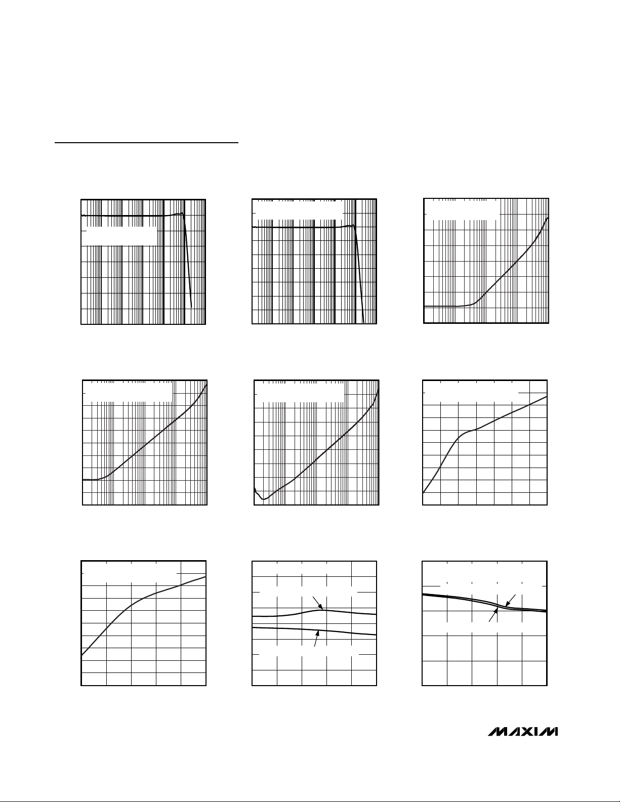
I
LOGIC
vs. V
LOGIC
V
LOGIC
(V)
I
LOGIC
(μA)
MAX5406 toc08a
2.7 3.1 3.5 3.9 4.3 4.7 5.1 5.5
0
20
40
60
80
100
120
140
160
180
200
VDD = 5.5V, VSS = 0
ACTIVE MODE (ONE BUTTON PUSHED)
TA = +25°C
TA = -40°C
TA = +85°C
I
LOGIC
vs. V
LOGIC
V
LOGIC
(V)
I
LOGIC
(nA)
MAX5406 toc08b
2.7 3.1 3.5 3.9 4.3 4.7 5.1 5.5
0
20
40
60
80
100
120
140
160
180
200
220
240
VDD = 5.5V, VSS = 0
INACTIVE MODE (NO BUTTON PUSHED)
TA = -40°C
TA = +85°C
TA = +25°C
THD PLUS NOISE vs. FREQUENCY
MAX5406 toc09a
FREQUENCY (kHz)
THD+N (%)
1010.1
0.01
0.1
1
0.001
0.01 100
VDD = V
LOGIC
= 5V, VSS = GND
V
IN
= 4.6V
P-P
RL = 10k
Ω
NO LOAD
10μs/div
WIPER SWITCHING TRANSIENT
MAX5406 toc07a
DC LEVEL AT
THE INPUT
OUTPUT
4ms/div
WIPER SWITCHING TRANSIENT
(SUPPRESSION CIRCUIT ACTIVE)
MAX5406 toc07b
5V
P-P
SINE WAVE
BETWEEN L1_H
AND L1_L
VOLUP
OUTPUT
Typical Operating Characteristics (continued)
(TA = +25°C, unless otherwise noted.)
THD PLUS NOISE vs. FREQUENCY
MAX5406 toc09b
FREQUENCY (Hz)
THD+N (%)
1010.10.01 100
0.1
0.01
VDD = V
LOGIC
= 2.7V, VSS = -2.7
V
IN
= 4.6V
P-P
RL = 10k
Ω
NO LOAD
FREQUENCY (Hz)
CROSSTALK (dB)
CROSSTALK vs. FREQUENCY
0
-10
-20
-30
-40
-50
-60
-70
-80
10
1k 10k 100k100 1M
MAX5406 toc10b
VDD = 2.7V, VSS = -2.7V, V
LOGIC
= 2.5V,
V
IN
= 1V
P-P
, RL = 10kΩ
FREQUENCY (Hz)
CROSSTALK (dB)
CROSSTALK vs. FREQUENCY
0
-10
-20
-30
-40
-50
-60
-70
-80
-90
10
1k 10k 100k100 1M
MAX5406 toc10a
VDD = V
LOGIC
= 5V, VSS = 0,
V
IN
= 1V
P-P
, RL = 10kΩ
TOTAL SUPPLY CURRENT
vs. SUPPLY VOLTAGE (I
DD
+ I
LOGIC
)
SUPPLY VOLTAGE (V)
SUPPLY CURRENT (mA)
MAX5406 toc11a
2.7 3.1 3.5 3.9 4.3 4.7 5.1 5.5
8.0
8.5
9.0
9.5
10.0
10.5
11.0
11.5
12.0
VDD = V
LOGIC
= 5V, VSS = 0
ACTIVE MODE, ONE BUTTON PUSHED
TA = +25°C
TA = +85°C
TA = -40°C
Page 10

MAX5406
Audio Processor with Pushbutton Interface
10 ______________________________________________________________________________________
0.9
0.7
0.5
0.3
0.1
-0.1
1.1
1.5
1.3
1.7
1.9
0.01 10.1 10 100
ROUT NOISE vs. FREQUENCY
MAX5406 toc12b
FREQUENCY (kHz)
NOISE (μV
RMS
/Hz)
VDD = V
LOGIC
= 2.7V, VSS = -2.7V
MUTE OFF
MUTE ON
-110
-90
-50
-70
-30
-10
1 10010 1000 10000
INPUT RF REJECTION
MAX5406 toc13
f1 FREQUENCY (MHz)
10kHz OUTPUT AMPLITUDE (f
2
-f
1
) = 10kHz(dBm)
VOLUME = 0dB
V
DD
= 2.7V, VSS = -2.7V
INPUT = 200mV
P-P
AT L1_H
1
0.8
0.6
0.4
0.2
0
1.2
1.6
1.4
1.8
2
0.01 10.1 10 100
SUBOUT NOISE vs. FREQUENCY
MAX5406 toc12c
FREQUENCY (kHz)
NOISE (μV
RMS
/Hz)
VDD = V
LOGIC
= 2.7V, VSS = -2.7V
-0.1
0.1
0.3
1.1
0.9
0.7
0.5
1.5
1.3
1.9
1.7
0.01 10.1 10 100
LOUT NOISE vs. FREQUENCY
MAX5406 toc12a
FREQUENCY (kHz)
NOISE (μV
RMS
/Hz)
VDD = V
LOGIC
= 2.7V, VSS = -2.7V
MUTE OFF
MUTE ON
Typical Operating Characteristics (continued)
(TA = +25°C, unless otherwise noted.)
TOTAL SUPPLY CURRENT
vs. SUPPLY VOLTAGE (I
DD
+ I
LOGIC
)
SUPPLY VOLTAGE (V)
SUPPLY CURRENT (mA)
MAX5406 toc11b
2.7 3.1 3.5 3.9 4.3 4.7 5.1 5.5
8.0
8.5
9.0
9.5
10.0
10.5
11.0
11.5
12.0
VDD = V
LOGIC
= 5V, VSS = 0
INACTIVE MODE, NO BUTTON PUSHED
TA = +25°C
TA = +85°C
TA = -40°C
Page 11

MAX5406
Audio Processor with Pushbutton Interface
______________________________________________________________________________________ 11
Pin Description
PIN
TSSOP
NAME
FUNCTION
143
Bypass Capacitor Connection Point to Internally Generated Bias. Bypass CBIAS with a 50µF
capacitor to system analog ground.
244VSSNegative Power-Supply Input. Bypass with a 0.1µF capacitor to system analog ground.
3 45 L1_H
Left-Channel 1 High Terminal Input. Connect the source between L1_H and L1_L for differential
signals. Connect the source to L1_H and tie L1_L to BIAS for single-ended signals.
4 46 L1_L
Left-Channel 1 Low Terminal Input. Connect the source between L1_H and L1_L for differential
signals. Connect L1_L to BIAS for single-ended signals.
5 47 L2_L
Left-Channel 2 Low Terminal Input. Connect the source between L2_H and L2_L for differential
signals. Connect L2_L to BIAS for single-ended signals.
6 48 L2_H
Left-Channel 2 High Terminal Input. Connect the source between L2_H and L2_L for differential
signals. Connect the source to L2_H and tie L2_L to BIAS for single-ended signals.
71LMR
Left Minus Right Output Signal. LMR output provides a signal that is the difference of left and right
input signals. See the Ambience Control section for more details.
82
Ambience Left-Channel Input. AMBLI provides the proper ambient effect at LOUT based on the
transfer function implemented between LMR and AMBLI. See the Ambience Control section for
more details.
9 3 CTL1
Left-Channel Treble Tone Control Capacitor Terminal 1. Connect a capacitor between CTL1 and
CTL2 to set the treble cutoff frequency. See the Tone Control section for more details.
10 4 CTL2
Left-Channel Treble Tone Control Capacitor Terminal 2. Connect a capacitor between CTL2 and
CTL1 to set the treble cutoff frequency. See the Tone Control section for more details.
11 5 CBL1
Left-Channel Bass Tone Control Capacitor Terminal 1. Connect a capacitor between CBL1 and
CBL2 to set the bass cutoff frequency. See the Tone Control section for more details.
12 6 CBL2
Left-Channel Bass Tone Control Capacitor Terminal 2. Connect a capacitor between CBL2 and
CBL1 to set the bass cutoff frequency. See the Tone Control section for more details.
13 7 LOUT Left-Channel Output
14 8 CLSN
Subwoofer Left-Channel Highpass Filter Capacitor Negative Terminal. Connect a capacitor
between CLSN and CLSP to set the highpass cutoff frequency at SUBOUT. See the Subwoofer
Ouput section for more details.
15 9 CLSP
Subwoofer Left-Channel Highpass Filter Capacitor Positive Terminal. Connect a capacitor between
CLSP and CLSN to set the highpass filter cutoff frequency at SUBOUT. See the Subwoofer Ouput
section for more details.
16 10
Subwoofer Output. Connect a capacitor from SUBOUT to CSUB to set the lowpass filter cutoff
frequency at SUBOUT. See the Subwoofer Ouput section for more details.
17 11 CSUB
S ub w oofer Low p ass Fi l ter C ap aci tor Ter m i nal . C onnect a fi l ter cap aci tor b etw een C S U B and S U BOU T
to set the l ow p ass fi l ter cutoff fr eq uency. S ee the S ub w oofer Oup ut secti on for m or e d etai l s.
18, 32
I.C. Internally Connected. Connect to DGND.
TQFN
CBIAS
AMBLI
SUBOUT
12, 26
Page 12

MAX5406
Audio Processor with Pushbutton Interface
12 ______________________________________________________________________________________
Pin Description (continued)
PIN
TSSOP
FUNCTION
19 13
Active-Low Mute Control Input. Toggles state between muted and not muted. When in the mute
state, all wipers are moved to the low end of the volume potentiometers. The last state is restored
when MUTE is toggled again. The power-on state is not muted. MUTE is internally pulled up with
50kΩ to V
LOGIC
.
20 14
Active-Low Downward Volume Control Input. Press VOLDN to decrease the volume. This
simultaneously moves left and right volume wipers towards higher attenuation. VOLDN is internally
pulled up with 50kΩ to V
LOGIC
.
21 15
Active-Low Upward Volume Control Input. Press VOLUP to increase the volume. This simultaneously
moves the left and right volume wipers towards the the lower attenuation. VOLUP is internally pulled
up with 50kΩ to V
LOGIC
.
22 16 BALL
Active-Low Left Balance Control Input. Press BALL to move the balance towards the left channel.
BALL is internally pulled up with 50kΩ to V
LOGIC
.
23 17
Active-Low Right Balance Control Input. Press BALR to move the balance towards the right channel.
BALR is internally pulled up with 50kΩ to V
LOGIC
.
24 18
Digital Ground
25 19
Digital Power-Supply Input. Bypass with 0.1µF to DGND.
26 20
Active-Low Shutdown Control Input. In shutdown mode, the MAX5406 stores every wiper’s last
position. Each wiper moves to the highest attenuation level of its corresponding potentiometer.
Terminating shutdown mode restores every wiper to its previous setting. In shutdown, the MAX5406
does not acknowledge any pushbutton command.
27 21
Active-Low Downward Bass Control Input. Press BASSDN to decrease bass boost. Bass boost
emphasizes the signal’s low-frequency components. BASSDN is internally pulled up with 50kΩ to
V
LOGIC
. To implement a bass-boost button, connect BASSDN to BASSUP. Presses then toggle the
state between flat and full bass boost on each button press.
28 22
Active-Low Upward Bass Control Input. Press BASSUP to increase bass boost. Bass boost
emphasizes the signal’s low frequency components. BASSUP is internally pulled up with 50kΩ to
V
LOGIC
. To implement a bass-boost button, connect BASSUP to BASSDN. Presses then toggle the
state between flat and full bass boost on each button press.
29 23
Active-Low Downward Treble Control Input. Press TREBDN to decrease the treble boost. Treble
boost emphasizes the signal’s high-frequency components. TREBDN is internally pulled up with
50kΩ to V
LOGIC
.
30 24
Acti ve- Low U p w ar d Tr eb l e C ontr ol Inp ut. P r ess TRE BUP to i ncr ease the tr eb l e b oost. Tr eb l e b oost
31 25 AMB
Active-Low Ambience Switch Control Input. Drive AMB low to toggle on/off the ambience function.
AMB is internally pulled up with 50kΩ to V
LOGIC
.
33 27
Subwoofer Right-Channel Highpass Filter Capacitor Negative Terminal. Connect a capacitor
between CRSN and CRSP to set the highpass cutoff frequency at SUBOUT. See the Subwoofer
Ouput section for more details.
34 28
Subwoofer Right-Channel Highpass Filter Capacitor Positive Terminal. Connect a capacitor between
CRSP and CRSN to set the highpass cutoff frequency at SUBOUT. See the Subwoofer Ouput
section for more details.
35 29
Right-Channel Output
TQFN
NAME
MUTE
VOLDN
VOLUP
BALR
DGND
V
LOGIC
SHDN
BASSDN
BASSUP
TREBDN
TREBUP
CRSN
CRSP
ROUT
em p hasi zes the si g nal ’ s hi g h- fr eq uency com p onents. TRE BUP i s i nter nal l y p ul l ed up w i th 50kΩ to V
LOGIC
.
Page 13

MAX5406
Audio Processor with Pushbutton Interface
______________________________________________________________________________________ 13
Pin Description (continued)
PIN
TSSOP
FUNCTION
36 30 CBR2
Right-Channel Bass Tone Control Capacitor Terminal 2. Connect a nonpolorized capacitor between
CBR2 and CBR1 to set the bass cutoff frequency. See the Tone Control section for more details.
37 31 CBR1
Right-Channel Bass Tone Control Capacitor Terminal 1. Connect a capacitor between CBR1 and
CBR2 to set the bass cutoff frequency. See the Tone Control section for more detail.
38 32 CTR2
Right-Channel Treble Tone Control Capacitor Terminal 2. Connect a capacitor between CTR2 and
CTR1 to set the treble cutoff frequency. See the Tone Control section for more details.
39 33 CTR1
Right-Channel Treble Tone Control Capacitor Terminal 1. Connect a capacitor between CTR1 and
CTR2 to set the treble cutoff frequency. See the Tone Control section for more details.
40 34
Ambience Right-Channel Input. AMBRI provides the proper ambient effect at ROUT based on the
gain between LPR and AMBRI. See the Ambience Control section for more details.
41 35 LPR
Left Plus Right Output Signal. LPR output provides a signal that is a combination of the left and right
input signals. See the Ambience Control section for more details.
42 36 V
DD
Positive Analog Supply Voltage. Bypass with a 0.1µF capacitor to system analog ground.
43 37 R2_H
Right-Channel High Terminal 2. Connect the source between R2_H and R2_L for differential signal.
Connect the source to R2_H and tie R2_L to BIAS for single-ended signals.
44 38 R2_L
Right-Channel Low Terminal 2. Connect the source between R2_H and R2_L for differential signal.
Connect R2_L to BIAS for single-ended signals.
45 39 R1_L
Right-Channel Low Terminal 1. Connect the source between R1_H and R1_L for differential signal.
Connect R1_L to BIAS for single-ended signals.
46 40 R1_H
Right-Channel High Terminal 1. Connect the source between R1_H and R1_L for differential signal.
Connect the source to R1_H and tie R1_L to BIAS for single-ended signals.
47 41
Common-Mode Voltage Sense. Connect to V
DD
to disable the internal bias generator and drive
BIAS with external source to set output DC level.
48 42 BIAS
Internally Generated Bias Voltage. Connect CMSNS to V
SS
to enable the internally generated
V
BIAS. VBIAS
= (V
DD + VSS
) / 2. Connect a 0.1µF capacitor between BIAS and system analog
ground as close to the device as possible. Do not use BIAS to drive external circuitry.
TQFN
NAME
AMBRI
CMSNS
Page 14

MAX5406
Audio Processor with Pushbutton Interface
14 ______________________________________________________________________________________
Detailed Description
The MAX5406 implements dual logarithmic potentiometers to control volume, dual potentiometers to control
balance, and dual linear digital potentiometers to set
the tone (Figure 1). A debounced pushbutton interface
is provided to control the audio-processor settings. The
MAX5406 provides differential buffered inputs with RF
filters to maximize noise reduction and a mixer to produce an equal amount of left and right input channels.
In addition to a differential output, the MAX5406 provides a monophonic output at SUBOUT for systems
with a subwoofer.
CMSNS
BIAS
GENERATOR
RIGHT
LOG POT
LEFT
LOG POT
CONTROLLED
BY AMB
LEFT AMBIENCE
SWITCH
CONTROLLED
BY AMB
RIGHT AMBIENCE
SWITCH
RF FILTER
RF FILTER
RF FILTER
RF FILTER
L1_H
L1_L
L2_H
L2_L
BIAS
R1_H
R1_L
R2_H
R2_L
DIGITAL INTERFACE
DGND
V
SS
LPR
AMBRI
V
LOGIC
SHDN
MUTE
AMB
BALL
BALR
VOLDN
VOLUP
BASSDN
BASSUP
TREBDN
TREBUP
CBR1 CBR2 CTR1 CTR2
CRSN
CRSP
SUBOUT
CSUB
CLSN
CLSP
LOUT
ROUT
CBL1 CBL2 CTL1 CTL2
V
DD
LMR
AMBLI
MAX5406
R
SUB
R
LS
R
RS
CBIAS
BASS/TREBLE OUTPUT STAGE
SEE FIGURE 7
BASS/TREBLE OUTPUT STAGE
SEE FIGURE 7
Figure 1. Block Diagram
Page 15

MAX5406
Audio Processor with Pushbutton Interface
______________________________________________________________________________________ 15
Up/Down Interface
The MAX5406 features independent control inputs for
volume, balance, ambience, and tone control. All control inputs are internally debounced for use with
momentary contact SPST switches. All switch inputs
are pulled up to V
LOGIC
through 50kΩ resistors. The
wiper setting advances once per button press held for
up to 1s (see Figures 2a and 2b). Maxim’s SmartWiper
control circuitry allows the wiper to advance at a rate of
4Hz when an input is held low from 1s up to 4s, and at
a rate of 16Hz if the contact is maintained for greater
than 4s without the need of a µP (see Figure 3 and
Table 1). The MAX5406 ignores multiple buttons being
pressed. A µP can also be used to control the
MAX5406.
Volume Control
The MAX5406 implements dual logarithmic potentiometers for volume control that change the sound level by
2dB per button push (see Table 2).
In volume-control mode, the MAX5406’s wipers move
up and down together (see Figure 4). The balance is
unaffected (see the Balance Control section). Left and
right balance settings are maintained when adjusting
the volume.
Balance Control
In balance-control mode, the MAX5406 uses dual
potentiometers to control balance for the left and right
channels. Pressing BALR increases the right channel
wiper by 1dB and decreases the left channel by 1dB.
This causes the right channel to sound louder than the
left channel by 2dB. The overall volume remains constant when adjusting the balance (Figure 5).
Volume and Balance Interaction
Volume and balance operation is simple. However,
there are some interactions that occur at the extreme
wiper positions. These interactions are described in this
section of the data sheet.
When the volume setting is at the maximum level, the
first command to move the balance toward the left channel forces the right channel to decrease by 1dB.
Subsequent pressing of BALL causes the right channel
to decrease by 2dB. At this position, shown in the right
column of Figure 6a, the left-channel volume is maximum, but the actual separation between L and R is 3dB.
At this position, pressing VOLDN restores the actual
balance setting only after VOLDN is pressed at least
half as many times as BALL was (previously) pressed
(shown in the middle and right column of Figure 6b) to
increase the right-channel balance.
The volume and balance interaction is similar when volume setting is at the minimum level.
Tone Control
The MAX5406 implements a linear potentiometer to
control the bass and treble over a range of ±10dB
using the recommended component values.
Note that the actual response achieved is determined
by the values of both external and internal components
and the design equations are somewhat interactive.
Use the values shown in the Electrical Characteristics
as a good starting point for choosing component values. These components yield shelf turnovers at 100Hz
(bass) and 10kHz (treble) with a total ±10dB of boost at
100Hz and 10kHz. The shoulder or flat portion of the
response is centered on 1kHz.
The circuit in Figure 7 shows the internal structure of
the tone-control system should modification to the
CONTACT
DURATION
WIPER ACTION
t < t
LPW
No motion (debouncing) (Figures 2a and 2b)
t
LPW
≤ t ≤ 1s
Wiper changes position once (Figures 2a
and 2b)
1s ≤ t < 4s
Wiper changes position at a rate of 4Hz
(Figure 3)
t ≥4s
Wiper changes position at a rate of 16Hz
(Figure 3)
Table 1. Wiper Action vs. Pushbutton
Contact Duration
POSITION ATTENUATION (dB)
00
12
24
….. …..
10 ( Power-on state) 20
….. …..
30 60
31 62
32 (Mute) > 90
Table 2. Attenuator Position For Volume
Potentiometers
Page 16

MAX5406
Audio Processor with Pushbutton Interface
16 ______________________________________________________________________________________
t
LPW
t
WS
VOLUP
WIPER
MOTION
Figure 2a. Single-Pulse Input
t
LPW
t
HPW
VOLUP
WIPER
MOTION
V
IH
V
IL
Figure 2b. Repetitive Input-Pulse Separation Time
t
A1
t
A2
WIPER
MOTION
VOLUP
1
f
A1
1
f
A1
1
f
A2
1
f
A2
1
f
A2
1
f
A2
V
IH
V
IL
Figure 3. Accelerated Wiper Motion
Page 17

MAX5406
Audio Processor with Pushbutton Interface
______________________________________________________________________________________ 17
response curve be desired. A combination of internal
resistors and external capacitors determine the
response of the circuit.
Use the following equations to calculate the external
capacitor values for the desired 3dB frequencies:
where R
BPOT
, nominally 116kΩ, is the bass poten-
tiometer (see Figure 7).
where RTis nominally 3.5kΩ (see Figure 7).
f
RC
TREBLE dB
TT
()
_
3
1
2=××π
f
RC
BASS dB
BPOT B
()
_
3
1
2=××π
LR
PRESS VOLUP
TWICE
PRESS VOLDN
ONCE
BALANCE SEPARATION
MAINTAINED
LR LR
Figure 4. Basic Volume-Control Operation
1dB PER STEP
LR
LR LR
VOLUME LEVEL IS SET
1dB PER STEP
PRESS BALR
ONCE
1dB PER STEP
PRESS BALR
ONCE
Figure 5. Basic Balance-Control Operation
1dB PER STEP
2dB PER STEP
FROM 6a
LR
LR
LR
LR
LR
LR
VOLUME LEVEL IS AT MAXIMUM
2dB PER STEP
PRESS VOLDN
ONCE
2dB PER STEP
PRESS VOLDN
ONCE
BALANCE COMPENSATION ENDS
TO 6b
2dB PER STEP
PRESS BALL
AGAIN
1dB PER STEP
PRESS BALL
ONCE
b)
a)
Figure 6. Volume and Balance Interaction
Page 18

MAX5406
Audio Processor with Pushbutton Interface
18 ______________________________________________________________________________________
Alternatively, the following formulas can be used to calculate and design for the bass and treble turnover frequencies:
where R
B
is nominally 40kΩ (see Figure 7).
Tables 3 and 4 show the effects of the external bass and
treble capacitance on the maximum output attentuation.
f
RR C
TREBLE TURNOVER
TB T
()
_
()
=
×+×
1
2π
f
RC
BASS TURNOVER
BB
()
_
=
××
1
2π
-1
+1
+1
LMR
AMBLI AMBRI
+2
Figure 8. Matrix Surround Configuration
-1
+1
+1
LMR
AMBLI AMBRI
AMBIENCE
NETWORK
Figure 9. Ambience Filter
C
B_1
C
T_1
C
B_2
C
T_2
C
T_
C
B_
C
_SP
BUFFER
INPUT
TREBLE POT
BASS POT
TO BIAS
40kΩ 116kΩ 40kΩ
3.5kΩ 17kΩ 3.5kΩ
_OUT
Figure 7. Bass/Treble Output Stage
-1
+1
+1
LPR
AMBLI AMBRI
PSEUDOSTEREO
NETWORK
Figure 10. Pseudostereo Filter
C
B_
(nF) CUT (dB) BOOST (dB)
0.00 -11.79 11.81
0.47 -11.25 11.26
1.80 -11.05 11.08
2.20 -10.95 10.96
2.70 -10.85 10.86
3.30 -10.60 10.62
4.70 -10.57 10.55
6.80 -10.10 10.15
8.20 -9.66 9.66
Table 3. Effect of Base Tone Control
Capacitor (CB_) on Bass Boost/Bass
Cut at 100Hz
C
T_
(nF) CUT (dB) BOOST (dB)
0.47 -7.80 7.66
1.80 -12.55 12.58
2.20 -12.89 12.95
2.70 -13.15 13.18
3.30 -13.33 13.34
4.70 -13.55 13.58
6.80 -13.59 13.61
8.20 -13.61 13.63
Open -13.79 13.75
Table 4. Effect of Treble Tone Control
Capacitor (CT_) on Treble Boost/Treble
Cut at 10kHz
Page 19

MAX5406
Audio Processor with Pushbutton Interface
______________________________________________________________________________________ 19
Ambience Control
Use the ambience function for boom boxes, headphones, desktop speakers, or other audio products
where the speakers are physically close together. A
stereo signal is designed to be played over speakers
that have a wide physical separation. The ears and
brain combine the sound from these two sources to
create a perception of sounds distributed in space. In
the case of headphones, this wide physical separation
does not exist, resulting in the sound apparently coming from somewhere inside the head. A similar situation
exists when the speakers are not widely separated, for
example when they are located on a desk or inside a
single enclosure. One way to compensate for this is to
increase the apparent separation of the L and R signals
arithmetically. The L and R signals can be modeled as
a channel-specific component added to a monocomponent. To emphasize the channel-specific component,
one needs to remove the opposite channel-specific
component from the monocomponent.
This function is accomplished with circuitry inside the
MAX5406 and external network. Control the ambience
effect with the AMB button that toggles between wide
(full effect) and normal (no ambience effect). Use the following equations for matrix surround (fixed ambience):
1
0
SWITCH
CONTACT
IS BOUNCING
SWITCH
CONTACT
IS STABLE
SWITCH
CONTACT
IS BOUNCING
READY TO ACCEPT
ANOTHER BUTTON PRESS
INPUT ACCEPTED
PUSHBUTTON PRESSED
t
LPW
t
WS
t
HPW
DEBOUNCE BY
WAITING FOR
STABLE LOW,
t
LPW
WAIT FOR
FIRST ZERO
CROSSING OR
TIMEOUT, t
WS
DEBOUNCE BY
WAITING FOR
STABLE HIGH, t
HPW
L1_H
L1_L
WIPER MOVES HERE
(t
LPW
+ tWS)
Figure 11a. Wiper Transition Timing Diagram (No Zero Crossing Detected)
Page 20

MAX5406
Audio Processor with Pushbutton Interface
20 ______________________________________________________________________________________
When F
L(S)
and F
R(S)
= 2 (LMR, AMBLI, and AMBRI are
connected with the multiplier network of Figure 8), the
equations become:
Use a passive filter network as shown in Figure 9 to filter
and delay the LMR signal in more advanced applications.
LOUT L R
ROUT R L
IN IN
IN IN
=
=
3
2
1
2
3
2
1
2
-
-
where
LR
is the signal at LMR
IN IN
-
4
⎛
⎝
⎜
⎞
⎠
⎟
.
LOUT L F
LR
ROUT R F
LR
IN L S
IN IN
IN R S
IN IN
=+ ×
=×
()
()
()
()
-
-
-
4
4
1
0
PUSHBUTTON PRESSED
SWITCH
CONTACT
IS BOUNCING
SWITCH
CONTACT
IS STABLE
SWITCH
CONTACT
IS BOUNCING
READY TO ACCEPT
ANOTHER BUTTON PRESS
INPUT ACCEPTED
t
LPW
t
WS
t
HPW
DEBOUNCE BY
WAITING FOR
STABLE LOW, t
IPW
WAIT FOR
FIRST ZERO
CROSSING, t
WS
DEBOUNCE BY
WAITING FOR
STABLE HIGH, t
HPW
WIPER MOTION
WIPER MOVES HERE
Figure 11b. Wiper Transition Timing Diagram (Zero Crossing Detected)
Page 21

MAX5406
Audio Processor with Pushbutton Interface
______________________________________________________________________________________ 21
Pseudostereo
Pseudostereo creates a sound approximating stereo
from a monophonic signal. Use the equations for pseudostereo response calculations:
Connect a pseudostereo network (F
L(S)
and F
R(S)
) as
shown in Figure 10 to filter and delay the LPR signal
and create the pseudo signal.
Click/Pop Suppression
The click/pop suppression feature reduces the audible
noise (clicks and pops) that results from wiper transitions. The MAX5406 minimizes this noise by allowing
the wiper position changes only when the potential
across the pot is zero. Thus, the wiper changes position only when the voltage at L_ is the same as the voltage at the corresponding H_. Each wiper has its own
suppression and timeout circuitry (see Figure 11a). The
MAX5406 changes wiper position after 32ms or when
high = low, whichever occurs first (see Figure 11b).
Power-On Reset
The MAX5406 initiates power-on reset when V
LOGIC
falls below 2.2V and returns to normal operation when
V
LOGIC
= +2.7V. A power-on reset places the volume in
the mute (-90dB) state and volume wipers gradually
move to -20dB over a period of 0.7s in 2dB steps if no
zero-crossing event is detected. All other controls
remain in the 0dB position.
Shutdown (
SHDN
)
The MAX5406 stores the current wiper setting of each
potentiometer in shutdown mode. The wipers move to
the mute position to minimize the signal out of LOUT
and ROUT. Returning from shutdown mode restores all
wipers to their previous settings. Button presses in
shutdown are ignored.
Mute Function (
MUTE
)
The MAX5406 features a mute function that sets the
volume typically 90dB attenuation relative to full scale.
Successive pulses on MUTE toggle its setting.
Activating the mute function forces all wipers to the low
side of the potentiometer chain. Deactivating the mute
function returns the wipers to their previous settings.
MUTE is internally pulled high with a 50kΩ resistor
to V
LOGIC
.
Multiple Button Pushes
The MAX5406 ignores simultaneous presses of two or
more buttons. Pushing more than one button at the
same time does not change the state of the wipers.
Additionally, further key presses are ignored for 50ms
after all keys have been released. The MAX5406 does not
respond to any logic input until the blocking period ends.
Bias Generator
The MAX5406 generates a midrail, (V
DD
+ VSS) / 2 bias
voltage, for use with the input amplifiers.
For normal single-supply operation and single-ended
signals, connect R1_L, L1_L, R2_L, and L2_L to V
BIAS
and V
SS
to ground.
Enable the V
BIAS
generator by connecting CMSNS to V
SS
or leave CMSNS unconnected. Disable the V
BIAS
generator by forcing CMSNS to VDD. For proper operation, do not
use V
BIAS
to power other circuitry.
where
LR
are the signals at LPR
IN IN
+
⎛
⎝
⎜
⎞
⎠
⎟
4
.
LOUT L F
LR
ROUT R F
LR
IN L S
IN IN
IN R S
IN IN
=+ ×
+
=×
+
()
()
()
()
4
4
-
LEFT CHANNEL
INPUT
RIGHT CHANNEL
INPUT
CLSP
CLSN
CSUB
C
CSUB
SUBOUT
CRSN
CRSP
C
CRS
C
CLS
R
RS
R
LS
R
SUB
V
BIAS
Figure 12. Subwoofer Output Stage
Page 22

MAX5406
Audio Processor with Pushbutton Interface
22 ______________________________________________________________________________________
Subwoofer Output
The subwoofer output of the MAX5406 combines and
filters the left and right inputs for output to a subwoofer.
Choose the capacitor values to set the bandpass filter
to frequencies between 15Hz and 100Hz.
Figure 12 shows the subwoofer output stage configuration. The subwoofer output is a monophonic signal produced by adding the left and the right input signals.
The amplifier of the subwoofer output stage produces a
bandpass response. Use the following formulas to
determine the cutoff frequencies for the bandpass filter:
where R_Sis RLSor RRSand has the nominal value of
13.8kΩ, R
CSUB
has the nominal value of 10.6kΩ, and
C
C_S
is C
CLS
or C
CRS.
The external capacitors are as
shown in Figure 12.
Applications Information
Bass Boost
Some simple products may not need a variable bass
tone control. It may be desirable for such products
to have a bass-boost pushbutton. Tie BASSUP and
BASSDN together to provide a bass-boost feature.
When tied together, the bass boost is toggled between
0dB and maximum by pressing BASSUP or BASSDN.
Unequal Source Levels
Audio sources input to the MAX5406 may not have the
same full-scale voltage swings. Use a resistor in series
with the higher voltage swing input source to reduce
the gain for that input.
For example, to reduce the gain by half, add a 10kΩ
resistor in series with L1_H and R1_H, and a 20kΩ in
series with L1_L and R1_L.
Chip Information
PROCESS: BiCMOS
f
RS C
f
RC
HIGHPASS
CS
LOWPASS
CSUB CSUB
=
×× ×
=
×× ×
1
2
1
2ππ
_
_
Page 23

MAX5406
Audio Processor with Pushbutton Interface
______________________________________________________________________________________ 23
44
43
42
41
40
39
38
37
36
35
1
2
3
4
5
6
7
8
9
10
R2_L
R2_H
V
DD
LPR
48
47
46
45
BIAS
CMSNS
R1_H
R1_L
L1_L
L1_H
V
SS
CBIAS
TOP VIEW
MAX5406
AMBRI
CTR1
CTR2
CBR1
AMBLI
LMR
L2_H
L2_L
CBR2
ROUT
CTL2
CTL1
34
33
32
31
30
29
28
27
26
25
CRSP
CRSN
I.C.
AMB
TREBUP
TREBDN
BASSUP
BASSDN
SHDN
V
LOGIC
11
12
13
14
15
16
17
18
19
CLSN
LOUT
CBL2
CBL1
I.C.
CSUB
SUBOUT
CLSP
VOLDN
MUTE
TSSOP
20
21
BALL
VOLUP
22
23
DGND
BALR
24
Pin Configurations
V
DD
LPR
CTR1
CTR2
ROUT
CRSP
CRSN
AMB
I.C.
CBR1
CBR2
AMBRI
CTL1
CTL2
CBL1
CBL2
LOUT
CLSN
CLSP
I.C.
SUBOUT
CSUB
AMBLI
LMR
BALR
DGND
V
LOGIC
BASSDN
TREBUP
TREBDN
BASSUP
BALL
VOLUP
VOLDN
MUTE
L2_L
L1_L
L1_H
V
SS
CBIAS
BIAS
CMSNS
R1_H
R1_L
R2_H
R2_L
L2_H
TQFN
MAX5406
SHDN
TOP VIEW
13
14
15
16
17
18
19
20
21
22
23
24
12
3
4
5
678
9
10
11
12
37
38
39
40
41
42
43
44
45
46
47
48
36 35
34
33
32
313029
28
27
26
25
Page 24

MAX5406
Audio Processor with Pushbutton Interface
24 ______________________________________________________________________________________
X2
V
LOGIC
DGND
CRSNCRSPCBL2CBL1CBR2CBR1
V
SS
R2_H
L2_H
SUBOUT
CSUB
CTL2
CTL1
CTR2
CTR1
SHDN
AMB
MUTE
L1_H
R1_H
LMR AMBLI LPR AMBRI
V
DD
V
DD
BASSUP
BASSDN
TREBUP
TREBDN
BALR
BALL
VOLUP
VOLDN
LOUT
ROUT
DGND
RIGHT
STEREO
HEADPHONE
JACK
LEFT
SENSE
LEFT
SPEAKER
RIGHT
SPEAKER
BTL
BTL
STEREO IN1
STEREO IN2 (AUX)
MAX9761
CELL PHONE, MP3,
OR ACCESSORY
CONNECTORS
CLSNCLSP
MAX5406
V
DD
V
SS
CMSNSBIAS
CBIAS
C
CTR
C
CTL
C
CBR
C
CBL
C
CRS
C
CLS
C
CSUB
X2
C
BIAS
2
V
DD
+ V
SS
( )
+2.7V TO V
DD
*OPTIONAL
*
TYPICAL APPLICATION CIRCUIT SHOWS MAX5406 INTERNAL BIAS VOLTAGE OPERATION AND AUXILLIARY INPUT MIXING.
V
LOGIC
DGND
Typical Application Circuit
Page 25

MAX5406
Audio Processor with Pushbutton Interface
______________________________________________________________________________________ 25
Package Information
(The package drawing(s) in this data sheet may not reflect the most current specifications. For the latest package outline information,
go to www.maxim-ic.com/packages
.)
E
2
E/
D/2
D
e
L1
A1AA2
DETAIL
A
e
e
(ND-1) X
L
DETAIL
L
k
B
L
e
(NE-1) X
E2/2
C
L
E2
C
L
e
PACKAGE OUTLINE
32, 44, 48, 56L THIN QFN, 7x7x0.8mm
21-0144
k
32, 44, 48L QFN.EPS
C
D2
L
D2/2
b
C
L
L
e
1
E
2
PACKAGE OUTLINE
32, 44, 48, 56L THIN QFN, 7x7x0.8mm
21-0144
2
E
2
Page 26

MAX5406
Audio Processor with Pushbutton Interface
Boblet
Maxim cannot assume responsibility for use of any circuitry other than circuitry entirely embodied in a Maxim product. No circuit patent licenses are
implied. Maxim reserves the right to change the circuitry and specifications without notice at any time.
26 ____________________Maxim Integrated Products, 120 San Gabriel Drive, Sunnyvale, CA 94086 408-737-7600
© 2006 Maxim Integrated Products Printed USA is a registered trademark of Maxim Integrated Products, Inc.
Package Information (continued)
(The package drawing(s) in this data sheet may not reflect the most current specifications. For the latest package outline information,
go to www.maxim-ic.com/packages
.)
48L TSSOP.EPS
NOTES:
1. DIMENSIONS D & E ARE REFERENCE DATUMS AND DO NOT INCLUDE MOLD FLASH.
2. MOLD FLASH OR PROTRUSIONS NOT TO EXCEED 0.15MM ON D SIDE, AND 0.25MM ON E SIDE.
3. CONTROLLING DIMENSION: MILLIMETERS.
4. THIS PART IS COMPLIANT WITH JEDEC SPECIFICATION MO-153, VARIATIONS, ED (48L), EE (56L).
5. "N" REFERS TO NUMBER OF LEADS.
6. THE LEAD TIPS MUST LIE WITHIN A SPECIFIED ZONE. THIS TOLERANCE ZONE IS DEFINED BY TWO PARALLEL
PLANES. ONE PLANE IS THE SEATING PLANE, DATUM (-C-), THE OTHER PLANE IS AT THE SPECIFIED DISTANCE
FROM (-C-) IN THE DIRECTION INDICATED.
7. MARKING IS FOR PACKAGE ORIENTATION REFERENCE ONLY.
8. NUMBER OF LEADS SHOWN ARE FOR REFERENCE ONLY.
SECTION C-C
DETAIL A
N
SIDE VIEW
TOP VIEW
C
L
1
HE
e
D
b
A
A2
A1
BOTTOM VIEW
c
0.25
()
b1
b
c1
BASE METAL
c
END VIEW
SEATING
PLANE
SEE DETAIL A
PARTING
LINE
WITH PLATING
L
PACKAGE OUTLINE,
21-0155
1
1
C
48 & 56L TSSOP, 6.1mm BODY
AAA23A
MARKING
 Loading...