

Page 1
General Description
The MAX5096/MAX5097 easy-to-use, Dual Mode™,
DC-DC converters operate as LDO (low dropout) or
switch-mode buck converters. At a high output load,
the converters operate as high-efficiency pulse-widthmodulated (PWM) switch-mode converters and reduce
the power dissipation. The devices switch to a low-quiescent-current (IQ) LDO mode of operation at light load.
During the key-off condition, the system’s microcontroller drives the LDO/BUCK input on the fly and forces
the MAX5096/MAX5097 into LDO Mode, thereby reducing the quiescent current significantly.
In Buck Mode, the MAX5096/MAX5097 operate from a 5V
to 40V input voltage range and deliver up to 600mA of
load current with excellent load and line regulation. The
fixed-switching frequency versions of 135kHz and
330kHz are available. The MAX5096/MAX5097 DC-DC
internal oscillator can be synchronized to an external
clock. External compensation and a current-mode control
scheme make it easy to design with.
In LDO Mode, the MAX5096/MAX5097 operate from a
4V to 40V input voltage. The LDO Mode operation is
intended for a lower output load current of up to
100mA. The quiescent current at 100µA load in LDO
Mode is only 41µA (typ).
The MAX5096/MAX5097 feature an enable input that
shuts down the device, reducing the current consumption to 6µA (typ). Additional features include a power-on
reset output with a capacitor-adjustable timeout period,
programmable soft-start, output tracking, output overload, short-circuit and thermal shutdown protections.
The MAX5096/MAX5097 operate over the -40°C to
+125°C automotive temperature range and are available in thermally enhanced 20-pin TSSOP or 16-pin
TQFN packages.
Applications
Automotive
Industrial
Features
♦ High-Efficiency Switcher Mode (Buck Mode) or
Low-Quiescent-Current Linear Regulator
(LDO Mode) Operation
♦ Wide Operating Input Voltage Range
+5V to +40V Buck Mode
+4V to +40V LDO Mode
♦ Fixed 3.3V or 5V and Adjustable (1.24V to 11V)
Output Voltage Versions
♦ 6µA (typ) Shutdown Current
♦ Fixed 135kHz or 330kHz Switching Frequency
♦ External Frequency Synchronization
♦ Programmable Soft-Start
♦ Integrated Microprocessor Reset (RESET) Circuit
with Programmable Timeout Period
♦ Thermal and Short-Circuit Protection
♦ -40°C to +125°C Automotive Temperature Range
♦ Thermally-Enhanced Package Dissipates
2.6W at TA= +70°C (16-Pin TQFN)
1.7W at TA= +70°C (20-Pin TSSOP)
MAX5096/MAX5097
40V, 600mA Buck Converters with Low-
Quiescent-Current Linear Regulator Mode
________________________________________________________________ Maxim Integrated Products 1
19-0603; Rev 0; 7/06
For pricing, delivery, and ordering information, please contact Maxim/Dallas Direct! at
1-888-629-4642, or visit Maxim’s website at www.maxim-ic.com.
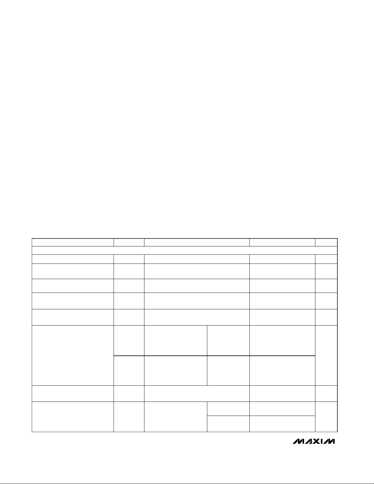
Ordering Information
PART
TEMP RANGE
PIN-PACKAGE
PKG
CODE
MAX5096AATE+*
T1655-2
MAX5096BATE+
T1655-2
MAX5096AAUP+*
U20E-4
MAX5096BAUP+*
U20E-4
MAX5097AATE+
T1655-2
MAX5097BATE+*
T1655-2
MAX5097AAUP+*
U20E-4
MAX5097BAUP+*
U20E-4
TQFN
+
LX
16
1
2
3
4
12
11
10
9
15 14 13
5678
IN
IN
LX
EN
OUT
ADJ
LDO/BUCK
SGND
RESET
BP
SYNC
SS
CT
COMP
PGND
MAX5096
MAX5097
TOP VIEW
20
19
18
17
16
15
14
1
2
3
4
5
6
7
LX
LX
N.C.
ENPGND
IN
IN
IN
TOP VIEW
MAX5096
MAX5097
OUT
ADJ
N.C.BP
138N.C.
129 COMPSYNC
1110 CTSS
SGND
TSSOP
LDO/BUCK
RESET
+
Pin Configurations
*Future product—contact factory for availability.
+Denotes lead-free package.
**EP = Exposed pad.
Dual Mode is a trademark of Maxim Integrated Products, Inc.
-40°C to +125°C 16 TQFN-EP**
-40°C to +125°C 16 TQFN-EP**
-40°C to +125°C 20 TSSOP-EP**
-40°C to +125°C 20 TSSOP-EP**
-40°C to +125°C 16 TQFN-EP**
-40°C to +125°C 16 TQFN-EP**
-40°C to +125°C 20 TSSOP-EP**
-40°C to +125°C 20 TSSOP-EP**
Page 2
MAX5096/MAX5097
40V, 600mA Buck Converters with LowQuiescent-Current Linear Regulator Mode
2 _______________________________________________________________________________________
ABSOLUTE MAXIMUM RATINGS
Stresses beyond those listed under “Absolute Maximum Ratings” may cause permanent damage to the device. These are stress ratings only, and functional
operation of the device at these or any other conditions beyond those indicated in the operational sections of the specifications is not implied. Exposure to
absolute maximum rating conditions for extended periods may affect device reliability.
(All voltages referenced to PGND, unless otherwise noted.)
IN (transient, 1ms) ..................................................-0.3V to +45V
SGND ....................................................................-0.3V to +0.3V
LX....................................................................-1V to (V
IN
+ 0.3V)
LX Current ................................................................................2A
EN ................................................................-0.3V to (V
IN
+ 0.3V)
BP, SYNC, LDO/BUCK, RESET to SGND...............-0.3V to +12V
BP, RESET Output Current..................................................25mA
CT, SS, ADJ, COMP to SGND ....................-0.3V to (V
BP
+ 0.3V)
OUT ........................................................................-0.3V to +11V
OUT Short-Circuit Duration ........................................Continuous
Continuous Power Dissipation (T
A
= +70°C)*
16-Pin TQFN (derate 33.3mW/°C above +70°C) ........2666mW
20-Pin TSSOP (derate 21.7mW/°C above +70°C) ......1739mW
Thermal Resistance:
(
θJA, 16-Pin TQFN)* ...................................................30.0°C/W
(θ
JC
, 16-Pin TQFN).......................................................1.7°C/W
(θ
JA
, 20-Pin TSSOP)* .................................................46.0°C/W
(θ
JC
, 20-Pin TSSOP)........................................................2°C/W
Operating Temperature Range .........................-40°C to +125°C
Junction Temperature......................................................+150°C
Storage Temperature Range .............................-60°C to +150°C
Lead Temperature (soldering, 10s) .................................+300°C
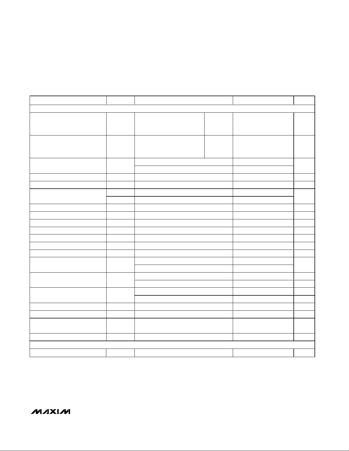
ELECTRICAL CHARACTERISTICS
(VIN= +14V, I
OUT
= 1mA, CIN= 100µF, C
OUT
= 22µF, L = 22µH, CBP= 1µF, VEN= +2.4V (Figure 2), SGND = PGND = 0V, TA= TJ=
-40°C to +125°C, unless otherwise noted. Typical values are at T
A
= TJ= +25°C.) (Note 1)
PARAMETER
SYMBOL
CONDITIONS
MIN
TYP
MAX
UNITS
SYSTEM INPUT
Input Voltage Range (LDO Mode)
LDO/BUCK = high 4 40 V
Input Voltage Range (Buck
Mode)
LDO/BUCK = low 5 40 V
Internal Input Undervoltage
Lockout
V
UVLO
VBP rising 3.5
3.9 V
Internal Input Undervoltage
Lockout Hysteresis
VBP falling
V
BP (Internal Regulator) Output
Voltage
V
BP
VIN = +4.5V, IBP = 100µA
4
V
I
Q
LDO/BUCK = high,
measured at input supply
return, V
OUT
= 5V,
I
OUT
= 100µA
T
A
= -40°C to
+125°C
41 70
Quiescent Supply Current
(LDO Mode)
I
Q
LDO/BUCK = high,
measured at input supply
return, V
OUT
= 5V,
I
OUT
= 100mA
T
A
= -40°C to
+125°C
44 100
µA
Buck Converter No-Load Supply
Current
VIN = 14V, V
OUT
= 5V, I
OUT
= 0
µA
TA = -40°C to
+125°C
619
Shutdown Supply Current I
SHDN
VEN = 0V, measured
from EN
T
A
= -40°C to
+85°C
612
µA
*As per JEDEC 51 Standard—Multilayer Board.
V
IN_LDO
V
IN_BUCK
3.65
V
UVLO_HYS
I
Q_BUCK
3.75
0.185
680
4.20
Page 3
MAX5096/MAX5097
40V, 600mA Buck Converters with Low-
Quiescent-Current Linear Regulator Mode
_______________________________________________________________________________________ 3
ELECTRICAL CHARACTERISTICS (continued)
(VIN= +14V, I
OUT
= 1mA, CIN= 100µF, C
OUT
= 22µF, L = 22µH, CBP= 1µF, VEN= +2.4V (Figure 2), SGND = PGND = 0V, TA= TJ=
-40°C to +125°C, unless otherwise noted. Typical values are at T
A
= TJ= +25°C.) (Note 1)
PARAMETER
CONDITIONS
UNITS
BUCK MODE
Supply Current
(Buck Converter On)
I
S
LDO/BUCK = low,
V
ADJ
= 1.4V, MAX5096,
no switching
135kHz
version
980 µA
Supply Current
(Buck Converter On)
I
S
LDO/BUCK = low,
V
ADJ
= 1.4V, MAX5097,
no switching
330kHz
Version
µA
5V version, 5.5V ≤ VIN ≤ 40V, no load
5
Fixed Output Voltage V
OUT
3.3V version, 5.5V ≤ VIN ≤ 40V, no load
3.3
V
ADJ Set Point V
FB
50% duty cycle, no load
V
ADJ Input Bias Current I
FB
V
ADJ
= 1.5V 5 100 nA
ADJ rising
Dual Mode ADJ Threshold
ADJ falling 62
mV
Maximum Duty Cycle D
MAX
V
ADJ
= 0.5V
%
Error Amplifier Transconductance
Gm
EA
V
COMP
= V
ADJ
, I
COMP
= ±10µA 55
210 µS
Adjustable Output Voltage Range
V
ADJ
V
Minimum Output Current I
OUT
VIN = 6.5V to 40V
mA
Switch Current Limit
VIN = 6V to 40V
1.5
A
Internal Switch On-Resistance
)
VIN = 14V, I
DRAIN
= 100mA 0.9 2.1 Ω
Switch Leakage Current I
SW_L
V
IN
= 40V, V
ADJ
= 1.5V
3µA
VIN = 14V, V
OUT
= 5V, I
OUT
= 400mA 85
Efficiency η
V
IN
= 14V, V
OUT
= 3.3V, I
OUT
= 400mA 81
%
MAX5096
148 kHz
Switching Frequency f
SW
MAX5097
350 kHz
MAX5096
500 kHz
Synchronization SYNC Input f
SYNC
MAX5097
500 kHz
SYNC Input High Threshold
VBP = 4V 2.0 V
SYNC Input Low Threshold
VBP = 4V 0.8 V
SYNC Input Minimum High Pulse
Width
ns
SYNC Input Leakage V
SYNC
=11V 1 µA
LDO MODE
Guaranteed Output Current I
OUT
(Note 2)
mA
SYMBOL
MIN TYP MAX
693
720 1000
4.85
3.196
1.189 1.237 1.280
V
ADJTH_R
V
ADJTH_F
I
SW_LIM
R
DS(ON
1.237 11.000
1.15
125
100
136
600
0.05
V
SYNCH
V
SYNCL
120 135
300 330
120
300
100
250
5.12
3.391
1.90
Page 4
MAX5096/MAX5097
40V, 600mA Buck Converters with LowQuiescent-Current Linear Regulator Mode
4 _______________________________________________________________________________________
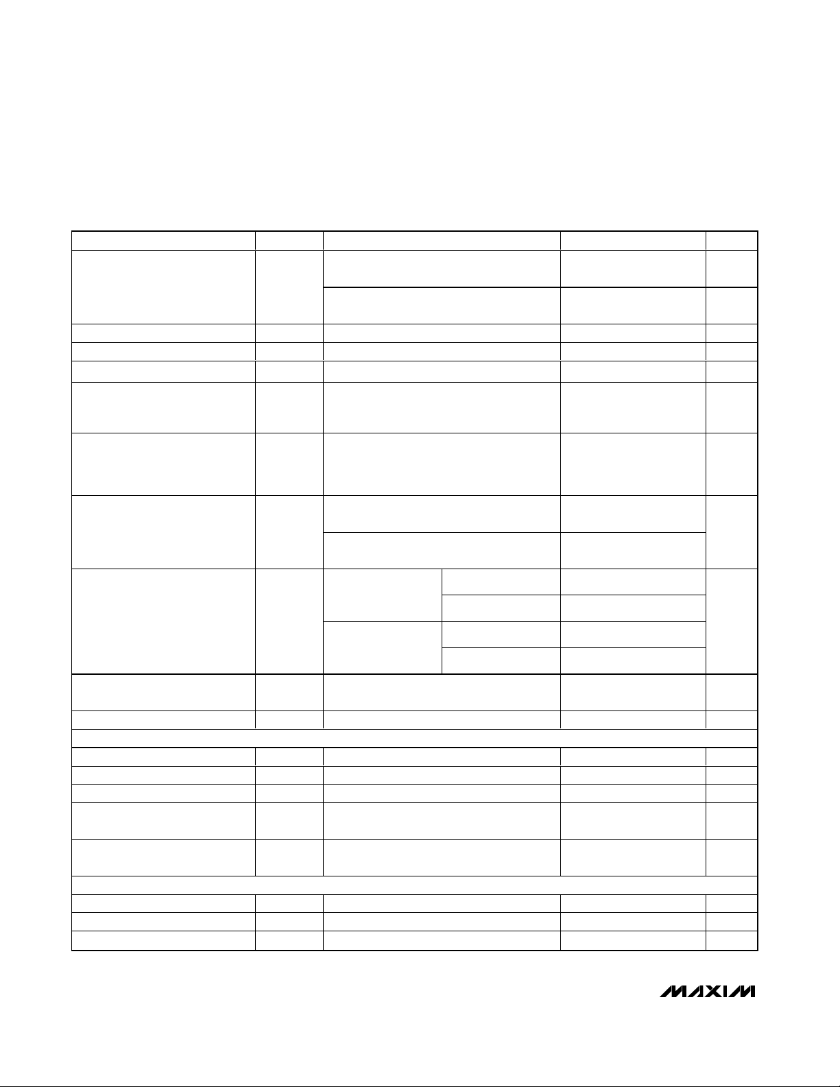
ELECTRICAL CHARACTERISTICS (continued)
(VIN= +14V, I
OUT
= 1mA, CIN= 100µF, C
OUT
= 22µF, L = 22µH, CBP= 1µF, VEN= +2.4V (Figure 2), SGND = PGND = 0V, TA= TJ=
-40°C to +125°C, unless otherwise noted. Typical values are at T
A
= TJ= +25°C.) (Note 1)
PARAMETER
CONDITIONS
UNITS
5V version, MAX5096B/MAX5097B,
5.5V ≤ V
IN
≤ 40V, I
OUT
= 10mA
5
V
Output Voltage V
OUT
3.3V version, MAX5096A/MAX5097A,
4V ≤ V
IN
≤ 40V, I
OUT
= 10mA
3.3
V
ADJ Set Point V
ADJ
I
OUT
= 10mA
V
ADJ Input Bias Current I
FB
V
ADJ
= 4V 0.5
nA
Adjustable Output Voltage Range
V
ADJ
I
OUT
= 10mA
V
Dropout Voltage ∆V
DO
I
OUT
= 100mA,
V
OUT
= 0.98 x V
OUT(NOMINAL)
(5V version
only), MAX5096B/MAX5097B
V
Startup Response Time
Rising edge of EN to
V
OUT
= 10% V
OUT(NOMINAL)
,
R
L
= 500Ω, V
ADJ
= SGND,
LDO/BUCK = 4V, C
SS
= 2nF
300 µs
5V version,
+5.5V ≤ V
IN
≤ +40V, I
OUT
= 100mA
Line Regulation
∆V
OUT
/
∆V
IN
3.3V version,
+4V ≤ V
IN
≤ +40V, I
OUT
= 100mA
mV/V
TJ = +25°C
5V version,
I
OUT
= 100µA to
1
TJ = +25°C
Load Regulation
∆V
OUT
/
∆I
OUT
3.3V version,
I
OUT
= 100µA to
1
mV/mA
Power-Supply Rejection Ratio PSRR
I
OUT
= 10mA, f = 100Hz, 500mV
P-P
,
V
OUT
= +5V, VIN = +14V
60 dB
Short-Circuit Current I
SC
VIN = 6V 150 330
mA
BUCK MODE (LDO MODE TRANSITION)
LDO/BUCK High Threshold 2.0 V
LDO/BUCK Low Threshold 0.8 V
LDO/BUCK Input Leakage LDO/BUCK = 11V 1 µA
Transition Timing from LDO Mode
to Buck Mode
Falling edge of LDO/BUCK to buck
converter on
32
Clock
Periods
Transition Timing from Buck
Mode to LDO Mode
Rising edge of LDO/BUCK to LDO
operation
100 µs
SOFT-START, ENABLE (EN) AND RESET
Soft-Start Charge Current I
SS
VSS = 0.1V 3 5 7 µA
Soft-Start Reference Voltage
V
OUT
= V
OUT(NOMINAL)
- 20% 0.9
1.1 V
EN High-Voltage Threshold V
ENH
EN = high, regulator on 1.4 V
SYMBOL
MIN TYP MAX
100mA, VIN = +14V
= -40°C to +125°C 0.242
T
J
100mA, VIN = +14V
= -40°C to +125°C 0.164
T
J
4.89
3.219
1.21 1.2375 1.26
1.237 11.000
0.125
0.093
0.242 0.374
0.164 0.237
5.09
3.378
100
0.37
500
V
SS-REF
0.99
Page 5
MAX5096/MAX5097
40V, 600mA Buck Converters with Low-
Quiescent-Current Linear Regulator Mode
_______________________________________________________________________________________ 5
ELECTRICAL CHARACTERISTICS (continued)
(VIN= +14V, I
OUT
= 1mA, CIN= 100µF, C
OUT
= 22µF, L = 22µH, CBP= 1µF, VEN= +2.4V (Figure 2), SGND = PGND = 0V, TA= TJ=
-40°C to +125°C, unless otherwise noted. Typical values are at T
A
= TJ= +25°C.) (Note 1)
PARAMETER
CONDITIONS
UNITS
EN Low-Voltage Threshold V
ENL
Regulator off 0.4 V
EN Input Pulldown VEN = 2V, LDO/BUCK = 4V 0.5 µA
RESET Voltage Threshold High
V
OUT
rising 90 92 94
% V
OUT
RESET Voltage Threshold Low
V
OUT
falling 87 90 92
% V
OUT
RESET Output-Low Voltage V
RL
I
SINK
= 1mA 0.2 V
RESET Output-High Leakage
Current
I
RH
V
RESET
= 5V, V
ADJ
= 1.5V 1 µA
RESET Output Minimum Timeout
Period
C
CT
= 0 25 µs
V
OUT
to RESET Delay V
OUT
falling 10mV/µs, CCT = 0 6 µs
Delay Comparator Threshold V
CT_TH
VCT rising
V
Delay Comparator Threshold
Hysteresis
mV
CT Charge Current I
CH
1
µA
CT Discharge Current I
DISCH
VCT = 1V
mA
THERMAL SHUTDOWN
Thermal Shutdown Temperature
)
Temperature rising
°C
Thermal Shutdown Hysteresis
)
20 °C
Note 1: Limits to -40°C are guaranteed by design.
Note 2: The continuous maximum output current from LDO is limited by package power dissipation.
SYMBOL
V
RESET_H
V
RESET_L
T
J(SHDN
∆T
J(SHDN
MIN TYP MAX
1.18 1.2374 1.29
100
0.74
13.8
+165
1.20
Page 6
MAX5096/MAX5097
40V, 600mA Buck Converters with LowQuiescent-Current Linear Regulator Mode
6 _______________________________________________________________________________________
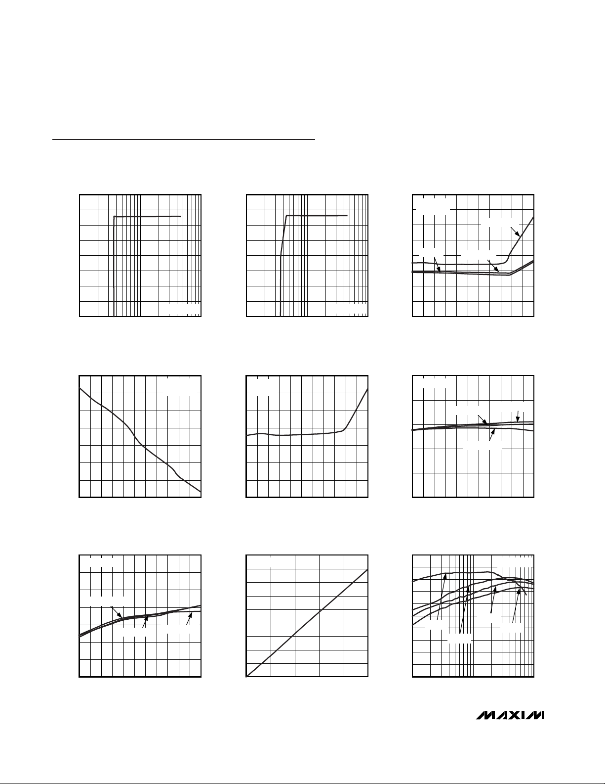
Typical Operating Characteristics
(VIN= +14V, VEN= +2.4V, MAX5097AATE+, Figures 2 and 4, TA= +25°C, unless otherwise specified.)
OUTPUT VOLTAGE vs. INPUT VOLTAGE
(LDO MODE)
MAX5096 toc01
INPUT VOLTAGE (V)
OUTPUT VOLTAGE (V)
10
0.5
1.0
1.5
2.0
2.5
3.0
3.5
4.0
0
1 100
I
OUT
= 50mA
OUTPUT VOLTAGE vs. INPUT VOLTAGE
(BUCK MODE)
MAX5096 toc02
INPUT VOLTAGE (V)
OUTPUT VOLTAGE (V)
10
0.5
1.0
1.5
2.0
2.5
3.0
3.5
4.0
0
1100
I
OUT
= 600mA
0
10
70
30
20
40
50
60
80
-40 -10 5 20-25 35 50 9580 11065 125
QUIESCENT SUPPLY CURRENT
vs. TEMPERATURE (LDO MODE)
MAX5096 toc03
TEMPERATURE (°C)
QUIESCENT SUPPLY CURRENT (µA)
VIN = 14V
V
OUT
= 3.3V
I
OUT
= 100mA
I
OUT
= 100µA
I
OUT
= 0
640
660
650
680
670
700
690
710
NO-LOAD SUPPLY CURRENT
vs. TEMPERATURE (BUCK MODE)
MAX5096 toc04
VIN = 14V
V
OUT
= 3.3V
-40 -10 5 20-25 35 50 9580 11065 125
TEMPERATURE (°C)
NO-LOAD SUPPLY CURRENT (µA)
0
4
2
8
6
12
10
14
SHUTDOWN CURRENT
vs. TEMPERATURE
MAX5096 toc05
-40 -10 5 20-25 35 50 9580 11065 125
TEMPERATURE (°C)
SHUTDOWN CURRENT (µA)
VEN = 0V
V
IN
= 14V
3.0
3.1
3.2
3.3
3.4
3.5
OUTPUT VOLTAGE vs. TEMPERATURE
(LDO MODE)
MAX5096 toc06
OUTPUT VOLTAGE (V)
-40 -10 5 20-25 35 50 9580 11065 125
TEMPERATURE (°C)
V
OUT
= 3.3V
I
OUT
= 10mA
I
OUT
= 100µA
I
OUT
= 10mA
3.24
3.28
3.26
3.32
3.30
3.36
3.34
3.38
OUTPUT VOLTAGE
vs. TEMPERATURE (BUCK MODE)
MAX5096 toc07
-40 -10 5 20-25 35 50 9580 11065 125
TEMPERATURE (°C)
OUTPUT VOLTAGE (V)
V
OUT
= 3.3V
I
OUT
= 100µA
I
OUT
= 100mA
I
OUT
= 600mA
0
0.04
0.02
0.10
0.08
0.06
0.16
0.14
0.12
0.18
04020 60 80 100
DROPOUT VOLTAGE
vs. OUTPUT CURRENT (LDO MODE)
MAX5096 toc08
OUTPUT CURRENT (mA)
DROPOUT VOLTAGE (V)
V
OUT
= 5V
0
30
20
10
40
50
60
70
80
90
100
0.01 0.1 1
EFFICIENCY vs. LOAD CURRENT
(V
OUT
= 3.3V)
MAX5096 toc09
LOAD CURRENT (A)
EFFICIENCY (%)
VIN = 5V
VIN = 14V
VIN = 24V
VIN = 40V
fSW = 330kHz
Page 7

MAX5096/MAX5097
40V, 600mA Buck Converters with Low-
Quiescent-Current Linear Regulator Mode
_______________________________________________________________________________________ 7
Typical Operating Characteristics (continued)
(VIN= +14V, VEN= +2.4V, MAX5097AATE+, Figures 2 and 4, TA= +25°C, unless otherwise specified.)
0
30
20
10
40
50
60
70
80
90
100
0.01 0.1 1
EFFICIENCY vs. LOAD CURRENT
(V
OUT
= 5V)
MAX5096 toc10
LOAD CURRENT (A)
EFFICIENCY (%)
VIN = 40V
VIN = 5.5V
VIN = 24V
VIN = 14V
2ms/div
LOAD-TRANSIENT RESPONSE
(LDO MODE)
I
OUT
50mA/div
V
OUT
50mV/div
MAX5096 toc11
VIN = 14V
I
OUT
= 100µA to 50mA
1ms/div
LOAD-TRANSIENT RESPONSE
(BUCK MODE)
I
OUT
200mA/div
V
OUT
AC-COUPLED
100mV/div
MAX5096 toc12
VIN = 14V
I
STEP
= 300mA to 600mA
10ms/div
VIN STARTUP RESPONSE
(LDO MODE)
V
IN
10V/div
RESET
5V/div
MAX5096 toc13
VIN = 14V
I
OUT
= 0A
C
CT
= 0.047µF
V
EN
10V/div
V
OUT
2V/div
10ms/div
ENABLE STARTUP RESPONSE
(LDO MODE)
V
IN
10V/div
RESET
5V/div
MAX5096 toc14
VIN = 14V
I
OUT
= 100mA
C
CT
= 0.047µF
V
EN
5V/div
V
OUT
2V/div
10ms/div
VIN STARTUP RESPONSE
(BUCK MODE)
V
IN
10V/div
RESET
5V/div
MAX5096 toc15
VIN = 14V
I
OUT
= 0A
C
CT
= 0.047µF
V
EN
5V/div
V
OUT
2V/div
10ms/div
ENABLE STARTUP RESPONSE
(BUCK MODE)
V
IN
10V/div
RESET
5V/div
MAX5096 toc16
VIN = 14V
I
OUT
= 600mA
C
CT
= 0.047µF
V
EN
5V/div
V
OUT
2V/div
100ms/div
SHUTDOWN RESPONSE THROUGH
V
IN
(LDO MODE)
V
IN
10V/div
RESET
5V/div
MAX5096 toc17
I
OUT
= 50mA
V
EN
10V/div
V
OUT
2V/div
100ms/div
SHUTDOWN RESPONSE THROUGH
V
IN
(BUCK MODE)
V
IN
10V/div
RESET
5V/div
MAX5096 toc18
I
OUT
= 50mA
V
EN
10V/div
V
OUT
2V/div
Page 8

MAX5096/MAX5097
40V, 600mA Buck Converters with LowQuiescent-Current Linear Regulator Mode
8 _______________________________________________________________________________________
Typical Operating Characteristics (continued)
(VIN= +14V, VEN= +2.4V, MAX5097AATE+, Figures 2 and 4, TA= +25°C, unless otherwise specified.)
2µs/div
LX VOLTAGE AND INDUCTOR CURRENT
MAX5096 toc19
I
OUT
= 0A
V
LX
5V/div
INDUCTOR
CURRENT
200mA/div
1µs/div
LX VOLTAGE AND INDUCTOR CURRENT
MAX5096 toc20
I
OUT
= 600mA
V
LX
10V/div
INDUCTOR
CURRENT
500mA/div
1µs/div
LX VOLTAGE, SYNC INPUT,
AND INDUCTOR CURRENT
MAX5096 toc21
V
LX
10V/div
INDUCTOR
CURRENT
500mA/div
SYNC INPUT
5V/div
400µs/div
TRANSITION FROM BUCK
MODE TO LDO MODE
MAX5096 toc22
LDO/BUCK
5V/div
I
OUT
100mA/div
V
OUT
AC-COUPLED
200mV/div
VIN = 14V
I
OUT
= 100mA
100µs/div
TRANSITION FROM LDO MODE
TO BUCK MODE
MAX5096 toc23
LDO/BUCK
3V/div
I
OUT
100mA/div
V
OUT
AC-COUPLED
200mV/div
VIN = 14V
I
OUT
= 100mA
Page 9

MAX5096/MAX5097
40V, 600mA Buck Converters with Low-
Quiescent-Current Linear Regulator Mode
_______________________________________________________________________________________ 9
Pin Description
PIN
TQFN TSSOP
NAME FUNCTION
14PGND
Power Ground. Return path for p-channel power MOSFET driver. Connect the input
capacitor return, freewheeling diode anode, and output capacitor return terminals to
PGND.
25SGND
Signal Ground. Connect SGND to PGND near the input bypass capacitor return terminal.
36RESET
Open-Drain, Active-Low Reset Output. RESET asserts low when OUT drops below the
reset threshold. When output rises above 92% of the programmed level, RESET
becomes high impedance after the reset timeout period. Connect a pullup resistor from
RESET to the converter output to create a logic output.
47BP
4V Internal Regulator Output. Bypass BP to SGND with a 1µF or greater ceramic
capacitor.
59SYNC
Synchronization Input. Connect SYNC to an external clock for synchronization. Connect
SYNC to SGND when not used.
610SS
Soft-Start Timer Input. Connect an external capacitor from SS to SGND to adjust the softstart timeout period (see the Soft-Start (SS) section).
711CT
Reset Timeout Period. Connect a capacitor from CT to SGND to set the reset timeout
period (see the Power-On Reset Output
RESET
section).
812COMP
Buck Converter (Buck Mode) Control Loop Compensation. See the Compensation
Network section for compensation network design. LDO mode does not need external
compensation.
913
LDO Mode/Buck Mode Select. Drive LDO/BUCK low to select the Buck Mode. The Buck
Mode activates after 32 internal/external clock cycles. Force the LDO/BUCK high (> 2V),
to select LDO Mode. The Buck Mode stops and LDO Mode is activated with a 100µs
delay.
10 15 ADJ
Regulator Output Feedback Point. Connect ADJ to SGND for a fixed 3.3V
(MAX5096A/MAX5097A) or 5V (MAX5096B/MAX5097B). For adjustable output voltage,
use an external resistive divider to set V
OUT
. V
ADJ
regulating set point is 1.237V.
11 16 OUT
Converter Output. OUT must always be connected to the regulator output. Connect at
least a 22µF low-ESR (equivalent series resistance) capacitor from OUT to PGND for
stable operation.
12 17 EN
Enable Input. EN is internally pulled to ground. Drive EN high to turn on the regulator.
Force EN low or leave unconnected to place the device in shutdown mode.
13, 14 19, 20 LX Drain Connection of Internal p-Channel High-Side Switch
15, 16 1, 2, 3 IN
Regulator Input. Bypass IN to PGND with a parallel combination of low-ESR ceramic and
aluminum capacitor to handle the input ripple current.
—8, 14, 18 N. C. No Connection. Not internally connected.
EP EP EP
Exposed Pad. Connect externally to a large ground plane (SGND) for improved heat
dissipation. Do not use EP as an electrical ground connection.
LDO/BUCK
Page 10

MAX5096/MAX5097
40V, 600mA Buck Converters with LowQuiescent-Current Linear Regulator Mode
10 ______________________________________________________________________________________
+
-
-
+
-
-
+
+
-
-
+
gm
V
REF
0.9Ω
CURRENT
LIMITER
RESET
INTERNAL
4V LDO
BP
IN
ADJ
LX
RESET
GATE
DRIVER
MUX
EN
PGND
LDO/BUCK
L
V
OUT
C
IN
PWM
C
OUT
SYNC
CT
SS
0.12V
FEEDBACK
SELECTOR
BUCK MODE GM
AMPLIFIER
FB
LDO/ BUCK
SELECTOR
PWM
COMPARATOR
DC-DC ENABLE
OSCILLATOR
AND RAMP
GENERATOR
MODE
SELECTOR
SS
OUT
LDO MODE
AMPLIFIER
SS
DC
CURRENT
SENSE
COMP
R
C
C
C
V
OUT
SGND
V
IN
FB
SYNCRO
C
BP
R
2
R
PU
R
1
C
SS
C
CT
BIAS SOFT-
START
INTERNAL
BANDGAP
UVLO
THERMAL
PROTECTION
V
REF
MAX5096
MAX5097
C
P
Figure 1. Simplified Diagram
Page 11

Detailed Description
The MAX5096/MAX5097 are easy-to-use, high-efficiency, PWM current-mode, step-down switching converters in normal operation. The MAX5096/MAX5097 have
an internal high-side p-channel 0.9Ω switch and use a
low forward-drop freewheeling diode for rectification. In
Buck Mode, the p-channel switches at the 135kHz or
330kHz frequency. Buck Mode uses a current-mode
control architecture that offers excellent line-transient
response, easier frequency compensation, and cycleby-cycle current limiting. The buck converter is compensated externally for a selected value/type of output
inductor and capacitor.
The internal p-channel switch acts as a pass element
when operating in the low-quiescent-current LDO
Mode.
The LDO Mode can be selected on the fly through the
LDO/BUCK input. During the key-off condition, the system’s microcontroller drives the LDO/BUCK input high
and forces the MAX5096/MAX5097 into LDO Mode,
reducing the quiescent current to 1µA (typ). When in
LDO Mode, the device is capable of delivering up to
100mA, which may be limited by the device power dissipation. The LDO and switcher share the same pass
element and the reference; however, the error amplifiers are different with their own compensation
schemes.
The MAX5096/MAX5097 include an integrated microprocessor reset circuit with an adjustable reset timeout
period. The internal reset circuit monitors the regulator
output voltage and asserts RESET low when the regulator output falls below the reset threshold voltage. Other
features include an enable input, externally programmable soft-start, optimized current-limit protection in
both LDO and Buck Modes, and thermal shutdown.
Enable Input (EN)
EN is a logic-level enable input that turns the device on
or off. The logic-high and logic-low voltages for the EN
input are 1.4V and 0.4V, respectively. Drive EN high to
turn on the device, and drive it low to place the device
in shutdown. Leaving EN unconnected disables the
device since the EN is internally pulled low with a 0.5µA
current, however, a forced pulldown of EN improves the
noise immunity. The MAX5096/MAX5097 draw 6µA
(typ) of supply current when in shutdown. EN withstands up to +40V, allowing EN to be connected directly to IN for always-on operation. The converter may be
turned on and off while in both Buck and LDO Modes.
Each time the EN is toggled, the output rises with a programmed soft-start period.
Internal Regulator (BP)/
Undervoltage Lockout
The MAX5096/MAX5097 include an internal 4V auxiliary
regulator to power internal circuitry. Bypass the auxiliary regulator output (BP) to SGND with a 1µF ceramic
capacitor physically located close to the device. The
regulator is not intended to supply the external circuit
other than pulling up the LDO/BUCK input or RESET.
Do not load BP externally by more than 2mA. The regulator output is regulated to 4V with 7% accuracy during
steady state. During turn-on, the BP voltage stabilizes
after 250µs with a 1µF capacitor at BP. Drive EN high to
turn on the internal regulator. The internal UVLO with
hysteresis ensures stable operation, resulting in the
monotonic rise of the output voltage. The UVLO circuit
monitors the output of the regulator. The rising UVLO
threshold is internally set to 3.65V (BP rising) with a
185mV hysteresis (BP falling). The 3.65V UVLO at the
no-load BP output guarantees operation at VINlower
than 4V.
Soft-Start (SS)
Soft-start provides for the monotonic, glitch-free turn-on
of the converter. Soft-start limits the input inrush current
which may cause a glitch, especially if the source
impedance is high. The soft-start period required also
depends on the output capacitance and the closedloop bandwidth of converter. The soft-start period for
the MAX5096/MAX5097 is externally programmable
using a single capacitor (CSS). The soft-start is
achieved by the controlled ramping up of the error
amplifier reference input. At startup, after VINis applied
and the UVLO threshold is reached, the device enters
soft-start. During soft-start, 5µA is sourced into the
capacitor (CSS) connected from SS to SGND (Figure 2)
causing the reference voltage to ramp up slowly. When
VSSreaches 1.237V, the output becomes fully active.
Set the soft-start time (tSS) using following equation:
where V
SS
is 1.237V, ISSis 5µA, tSSis in seconds, and
CSSis in Farads.
Pulling EN low quickly discharges the CSScapacitor,
making it ready for the next soft-start period.
t
V
I
C
SS
SS
SS
SS
=×
MAX5096/MAX5097
40V, 600mA Buck Converters with Low-
Quiescent-Current Linear Regulator Mode
______________________________________________________________________________________ 11
Page 12

MAX5096/MAX5097
Output Voltage Tracking/Sequencing
The output voltages of multiple MAX5096/MAX5097
converters can be made to track by using the SS pin
during turn-on and turn-off (see Figure 3). SS is pulled
up using a 5µA current source and connecting SS of
multiple MAX5096/MAX5097s, raising the references
with the same slope. Tracking the converters reduces
the differential voltages between the core and I/O voltages during turn-on, turn-off, and brownout. If any one
converter output drops due to shutdown or an overload
fault situation, the SS drops, pulling down all the converters simultaneously. The rate of fall of output voltages, however, depends on the output capacitance
and load of the individual converter.
Multiple voltage sequencing can be done by daisychaining several MAX5096/MAX5097s. The RESET of
the first converter can be connected to EN of the second converter. This allows the first converter to come
up first every time the system is powered up.
Power-On Reset Output (
RESET
)
A supervisor circuit is integrated in the MAX5096/
MAX5097. RESET is an open-drain output. RESET pulls
low as soon as V
OUT
drops below 90% of its nominal
regulation voltage. Once the output voltage rises above
92% of the set output voltage, the RESET output enters
a high-impedance state after the active timeout period
(tRP). The active timeout period is externally programmable using a single capacitor from CT to ground. Use
the following equation to calculate the required timeout
period for the power-on reset:
where V
CT-TH
is 1.237V, ICHis 1µA, tRPis in seconds,
and CCTis in Farads.
To obtain a logic-voltage output, connect a pullup
resistor from RESET to a logic-supply voltage. The
internal open-drain MOSFET can sink 1mA while providing a TTL logic-low signal. If unused, ground RESET or
leave it unconnected.
The power-on reset behavior is the same in both the
LDO and Buck Modes of operation.
Oscillator/Synchronization Input (SYNC)
The MAX5096/MAX5097 internal oscillator generates a
factory-preset frequency of either 135kHz (MAX5096)
or 330kHz (MAX5097). The 135kHz version keeps the
maximum fundamental frequency below 150kHz, which
keeps the third harmonic below 450kHz and under the
t
V
I
C
RP
CT TH
CH
CT
=×
−
40V, 600mA Buck Converters with LowQuiescent-Current Linear Regulator Mode
12 ______________________________________________________________________________________
PGND
OUT
LX
V
IN
GND
BP
V
IN
V
OUT
ADJ
22µH
C
OUT
22µF
(CER.)
COMP
SYNC
D1*
B260/
MURS105
C
IN
100µF
LDO/BUCK
RESET
EN
CT
SS
C
P
22pF
C
SS
0.047µF
C
CT
0.01µF
100kΩ
+
1.0µF
MAX5096
MAX5097
R
C
100kΩ
C
C
1.2nF
*USE MURS105 IN APPLICATIONS
WHERE LDO MODE QUIESCENT
CURRENT IS CRITICAL.
RESET
Figure 2. Fixed Output Voltage Configuration
Page 13

lower end of the AM band. The MAX5096 is suitable for
noise-sensitive applications like AM radio power supply. For an application where size is more important,
use the MAX5097, which runs at 330kHz frequency.
The high-frequency operation reduces the size and
cost of the external inductor and capacitor. The
MAX5096/MAX5097 can be synchronized using an
external signal. The MAX5096 can be synchronized
from 120kHz to 500kHz, while the MAX5097 is capable
of synchronizing from 300kHz to 500kHz. The external
synchronization feature makes frequency hopping possible depending on the selected AM channel. Connect
SYNC to ground, if not used.
Thermal Protection
When the junction temperature exceeds TJ= +165°C,
an internal thermal sensor signals the shutdown logic,
which turns off the regulator (both in Buck Mode and
LDO Mode), and discharges the soft-start capacitor
allowing the IC to cool. The thermal sensor turns the
regulator on again after the IC’s junction temperature
cools by 20°C, resulting in a cycled output during continuous thermal-overload conditions. The thermal hysteresis and a soft-start period limit the average power
dissipation into the device during continuous fault condition. During operation, do not exceed the absolute
maximum junction temperature rating of TJ= +150°C.
Applications Information
Output Voltage Selection
The MAX5096/MAX5097 can be configured as either a
preset fixed output voltage or an adjustable output voltage device. Connect ADJ to ground to select the factory-preset output voltage option (Figure 2). The
MAX5096A/MAX5097A and MAX5096B/MAX5097B
provide a fixed output voltage equal to 3.3V and 5V,
respectively (see the Selector Guide). The MAX5096/
MAX5097 become an adjustable version as soon as the
devices detect about 125mV at the ADJ pin. The resistor-divider at ADJ increases the ADJ voltage above
125mV and also adjusts the output voltage depending
upon the resistor values. In adjustable mode, select an
output between +1.273V and +11V using two external
resistors connected as a voltage-divider to ADJ (Figure
4). Set the output voltage using the following equation:
where V
ADJ
= 1.273V and R2 is chosen to be approxi-
mately 100kΩ.
Connect ADJ to GND if adjustable mode is not used.
Inductor Selection
Three key inductor parameters must be specified for
proper operation with the MAX5096/MAX5097: inductance value (L), peak inductor current (I
PEAK
), and
inductor saturation current (I
SAT
). The minimum
required inductance is a function of operating frequency, input-to-output voltage differential, and the peak-topeak inductor current (∆I
P-P
). Higher ∆I
P-P
allows for a
lower inductor value, while a lower ∆I
P-P
requires a
higher inductor value. A lower inductor value minimizes
size and cost and improves large-signal and transient
response, but reduces efficiency due to higher peak
currents and higher peak-to-peak output voltage ripple
for the same output capacitor. On the other hand, higher inductance increases efficiency by reducing the ripple current. Resistive losses due to extra wire turns can
exceed the benefit gained from lower ripple current levels, especially when the inductance is increased while
keeping the dimension of the inductor constant. A good
compromise is to choose ∆I
P-P
equal to 40% of the full
load current. Calculate the inductor value using the following equation:
L
VVV
Vf I
OUT IN OUT
IN SW P P
=
−
××
−
()
∆
VV
R
R
OUT ADJ
=×+
1
1
2
MAX5096/MAX5097
40V, 600mA Buck Converters with Low-
Quiescent-Current Linear Regulator Mode
______________________________________________________________________________________ 13
V
OUT3
V
OUT2
V
OUT1
SOFT-START
STOP
RATIOMETRIC TRACKING OUTPUTS
SEQUENCED OUTPUTS
STOP
SOFT-START
V
OUT3
V
OUT2
V
OUT1
Figure 3. Output Voltage Tracking/Sequencing
Page 14

MAX5096/MAX5097
use typical values of VINand fSWso that efficiency is optimum for typical conditions. The switching frequency (f
SW
)
is fixed at 135kHz (MAX5096) and 330kHz (MAX5097).
f
SW
can also be varied from 120kHz to 500kHz
(MAX5096) and from 300kHz to 500kHz (MAX5097) when
synchronized to an external clock (see the Oscillator/
Synchronization Input (SYNC) section). The peak-to-peak
inductor current, which reflects the peak-to-peak output
ripple, is worst at the maximum input voltage. See the
Output Capacitor Selection section to verify that the
worst-case output ripple is acceptable. The inductor saturating current (I
SAT
) is also important to avoid runaway
current during continuous output short circuit. Select an
inductor with an I
SAT
specification higher than the maxi-
mum peak current limit of 1.9A.
The Buck Mode operation determines the inductor and
output capacitor values. However, the values of the
inductor, its DCR, and the output capacitance/ESR
affect the closed-loop transfer function both in Buck
and LDO Modes. The internal compensation of the
MAX5096/MAX5097 in LDO Mode limits the values of
these external components. Make sure that the combination of output inductor, capacitor, and ESR falls within the range specified in following Table 1.
Output Capacitor Selection
The allowable output voltage ripple and the maximum
deviation of the output voltage during load steps determine the output capacitance and its ESR. The output
40V, 600mA Buck Converters with LowQuiescent-Current Linear Regulator Mode
14 ______________________________________________________________________________________
PGND
OUT
LX
V
IN
GND
BP
5V TO 40V
V
IN
V
OUT
ADJ
22µH
C
OUT
22µF
COMP
SYNC
D1*
B260/
MURS105
C
IN
100µF
LDO/BUCK
RESET
EN
R
C
C
C
CT
SS
C
P
R
PU
+
1.0µF
MAX5096
MAX5097
R1
R2
C
CT
C
SS
RESET
*USE MURS105 IN APPLICATIONS
WHERE LDO MODE QUIESCENT
CURRENT IS CRITICAL.
Figure 4. Adjustable Output Voltage Configuration
INDUCTOR
OUTPUT CAPACITOR (C
OUT
)
22µF, ESR = 5mΩ to 20mΩ (ceramic)
47µF, ESR = 40mΩ to 150mΩ
100µF, ESR = 30mΩ to 100mΩ
22µH
470µF / ESR = 60Ω to 400mΩ
22µF, ESR = 5mΩ to 20mΩ (ceramic)
47µF / ESR = 40mΩ to 150mΩ
100µF / ESR = 30mΩ to 100mΩ
47µH
470µF / ESR = 60mΩ to 400mΩ
22µF, ESR = 5mΩ to 20mΩ (ceramic)
47µF / ESR = 40mΩ to 150mΩ
100µF / ESR = 30mΩ to 100mΩ
100µH
470µF / ESR = 60mΩ to 400mΩ
Table 1. Inductor/Output Capacitor
Selection
Page 15

ripple is mainly composed of ∆VQ(caused by the
capacitor discharge) and ∆V
ESR
(caused by the voltage drop across the ESR of the output capacitor).
Normally, a good approximation of the output voltage
ripple is ∆V
RIPPLE
≈∆V
ESR
+ ∆VQ. If using ceramic
capacitors, assume the contribution to the output voltage ripple from the ESR and the capacitor discharge to
be equal to 20% and 80%, respectively. If using aluminum electrolyte capacitors, assume the contribution
to the output voltage ripple from the ESR and the
capacitor discharge to be equal to 90% and 10%,
respectively.
Use the following equations for calculating the output
capacitance and its ESR for required peak-to-peak output voltage ripple.
∆I
P-P
is the peak-to-peak inductor current and fSWis
the converter’s switching frequency.
The allowable deviation of the output voltage during
fast load transients also determines the output capacitance, its ESR, and its equivalent series inductance
(ESL). The output capacitor supplies the load current
during a load step until the controller responds with a
greater duty cycle. The response time (t
RESPONSE
)
depends on the closed-loop bandwidth of the converter
(see the Compensation Network section). The resistive
drop across the output capacitor’s ESR, the drop
across the capacitor’s ESL, and the capacitor discharge, causes a voltage drop during the load step.
Use a combination of low-ESR tantalum/aluminum electrolytic and ceramic capacitors for better transient load
and voltage ripple performance. Non-leaded capacitors and/or multiple parallel capacitors help reduce the
ESL. Keep the maximum output voltage deviation
below the tolerable limits of the electronics being powered. Use the following equations to calculate the
required ESR, ESL, and capacitance value during a
load step:
where I
STEP
is the load step, t
STEP
is the rise time of the
load step, and t
RESPONSE
is the response time of the
controller. The response time of the converter is
approximately one third of the inverse of its closed-loop
bandwidth and also depends on the phase margin.
Rectifier Selection
The MAX5096/MAX5097 require an external Schottky/
fast-recovery diode rectifier as a freewheeling diode.
Connect this rectifier close to the device using short
leads and short PC board traces. Choose a rectifier
with a continuous current rating greater than the highest output current-limit threshold (1.9A) and with a voltage rating greater than the maximum expected input
voltage, VIN. Use a low forward-voltage-drop Schottky
rectifier to limit the negative voltage at LX. Avoid higher
than necessary reverse-voltage Schottky rectifiers that
have higher forward-voltage drops. Use a 60V (max)
Schottky rectifier with a 2A current rating. The Schottky
rectifier leakage current at high temperature significantly increases the quiescent current in LDO Mode. In
applications where LDO Mode quiescent current is
important, use an ultra-fast switching diode to limit the
leakage current. In this type of application, use
MURS105, MURS120 for their fast-switching and lowleakage features.
Input Capacitor Selection
The discontinuous input current of the buck converter
causes large input ripple currents and therefore, the
input capacitor must be carefully chosen to keep the
input voltage ripple within design requirements. The
input voltage ripple is comprised of ∆VQ(caused by
the capacitor discharge) and ∆V
ESR
(caused by the
ESR of the input capacitor). The total voltage ripple is
the sum of ∆VQand ∆V
ESR
. Calculate the input capacitance and ESR required for a specified ripple using the
following equations (continuous mode):
I
OUT_MAX
is the maximum output current and D is the
duty cycle.
ESR
V
I
I
C
IDD
Vf
where
I
VV V
Vf L
and
D
V
V
ESR
OUT MAX
PP
IN
OUT MAX
QSW
PP
IN OUT OUT
IN SW
OUT
IN
=
+
=
×−
×
=
−×
××
=
−
−
∆
∆
∆
∆
_
_
()
()
2
1
ESR
V
I
C
It
V
ESL
Vt
I
ESR
STEP
OUT
STEP RESPONSE
Q
ESL STEP
STEP
=
=
×
=
×
∆
∆
∆
∆
C
I
Vf
ESR
V
I
OUT
PP
QSW
ESR
PP
=
××
=
−
−
∆
∆
∆
∆
16
MAX5096/MAX5097
40V, 600mA Buck Converters with Low-
Quiescent-Current Linear Regulator Mode
______________________________________________________________________________________ 15
Page 16

MAX5096/MAX5097
Compensation Network
The MAX5096/MAX5097 in LDO Mode are compensated internally with a compensation network around the
LDO error amplifier. When in Buck Mode, the DC-DC
gMamplifier must be externally compensated using a
network connected from COMP to ground. The currentmode control architecture reduces the compensation
network to a single pole-zero. The RC and C network,
connected from the internal transconductance amplifier
output to SGND, can provide a single pole-zero pair.
Choose all the power components like the inductor,
output capacitor, and ESR first and design the compensation network around them. Choose the closedloop bandwidth (fC) to be approximately 1/10 of the
switching frequency. See the following equations to calculate the compensation values for the low-ESR output
capacitor with ESR zero frequency, approximately a
decade higher than fC.
Calculate the dominant pole due to the output capacitor (C
OUT
) and the load (R
OUT
):
where R
OUT
= V
OUT
/ I
LOAD
.
Calculate the RCusing following equation:
where gMCis the control to output gain of the
MAX5096/MAX5097 buck converter and is equal to
1.06. V
ADJ
is the feedback set point equal to 1.237V
and gm(transconductance amplifier gain) is equal to
136µS. See Figure 2.
Place a zero (fZ) at 0.9 x fPO:
Finally, place a high-frequency pole at the frequency
equal to half of the converter switching frequency (fSW).
Place the compensation network physically close to the
MAX5096/MAX5097.
Switching Between LDO Mode
and Buck Mode
The MAX5096/MAX5097 switch between the Buck
Mode and LDO Mode on the fly. However, care must
be taken to reduce output glitch or overshoot during
the switching.
Buck Mode to LDO Mode
The LDO Mode is intended for the low 100mA output
current while the buck converter delivers up to 600mA
output current. It is important to first reduce the output
load below 100mA before switching to the LDO Mode.
If the output load is higher than 100mA, the
MAX5096/MAX5097 may go into the current limit and
the output will drop significantly. Whenever the mode is
changed, output is expected to glitch because the loop
dynamics change due to different error amplifiers when
operating in the LDO and Buck Modes. The output voltage undershoot can be minimized by reducing the output load during switching and using larger output
capacitance.
LDO Mode to Buck Mode
When switching from the LDO Mode to Buck Mode, a
fixed amount of delay (32 cycles) is applied so that the
buck converter control loop and oscillator reach their
steady-state conditions. The 32-cycle delay translates
to approximately 250µs and 100µs for 150kHz and
330kHz switching frequency versions, respectively. It is
recommended that the output load of 600mA must be
delayed by at least this much time to allow the
MAX5096/MAX5097 to switch to high-current Buck
Mode. This ensures that the output does not drop due
to the LDO current-limit protection mechanism.
PC Board Layout Guidelines
1) Proper PC board layout is essential. Minimize
ground noise by connecting the anode of the freewheeling rectifier, the input bypass capacitor
ground lead, and the output filter capacitor ground
lead to a large PGND plane.
2) Minimize lead lengths to reduce stray capacitance,
trace resistance, and radiated noise. In particular,
place the Schottky/fast recovery rectifier diode right
next to the device.
C
Rf
P
CSW
=
××
1
π
C
Rf
C
CFPO PO
=
×× ×
1
2 π
R
Vf
gR gV f
C
OC
MC OUT m ADJ PO
=
×
××××
f
CR
PO
OUT OUT
=
×× ×
1
2 π
40V, 600mA Buck Converters with LowQuiescent-Current Linear Regulator Mode
16 ______________________________________________________________________________________
Page 17

MAX5096/MAX5097
40V, 600mA Buck Converters with Low-
Quiescent-Current Linear Regulator Mode
______________________________________________________________________________________ 17
PART
OUTPUT
VOLTAGE
(V)
SWITCHING
FREQUENCY
(kHz)
MAX5096A_ _ _
135
MAX5096B_ _ _
135
MAX5097A_ _ _
330
MAX5097B_ _ _
330
Selector Guide
Chip Information
PROCESS: BiCMOS
3) Connect the exposed pad of the IC to the SGND
plane. Do not make a direct connection between the
exposed pad plane and SGND (pin 2) under the IC.
Connect the exposed pad and pin 2 to the SGND
plane separately. Connect the ground connection of
the feedback resistive divider, the soft-start capacitor, the adjustable reset timeout capacitor, and the
compensation network to the SGND plane. Connect
the SGND plane and PGND plane at one point near
the input bypass capacitor at VIN.
4) Use the large SGND plane as a heatsink for the
MAX5096/MAX5097. Use large PGND and LX
planes as heatsinks for the rectifier diode and the
inductor.
+3.3/Adjustable
+5.0/Adjustable
+3.3/Adjustable
+5.0/Adjustable
Page 18

MAX5096/MAX5097
40V, 600mA Buck Converters with LowQuiescent-Current Linear Regulator Mode
18 ______________________________________________________________________________________
Package Information
(The package drawing(s) in this data sheet may not reflect the most current specifications. For the latest package outline information,
go to www.maxim-ic.com/packages
.)
QFN THIN.EPS
Page 19

MAX5096/MAX5097
40V, 600mA Buck Converters with Low-
Quiescent-Current Linear Regulator Mode
______________________________________________________________________________________ 19
Package Information (continued)
(The package drawing(s) in this data sheet may not reflect the most current specifications. For the latest package outline information,
go to www.maxim-ic.com/packages
.)
Page 20

MAX5096/MAX5097
40V, 600mA Buck Converters with LowQuiescent-Current Linear Regulator Mode
Maxim cannot assume responsibility for use of any circuitry other than circuitry entirely embodied in a Maxim product. No circuit patent licenses are
implied. Maxim reserves the right to change the circuitry and specifications without notice at any time.
20 ____________________Maxim Integrated Products, 120 San Gabriel Drive, Sunnyvale, CA 94086 408-737-7600
© 2006 Maxim Integrated Products is a registered trademark of Maxim Integrated Products, Inc.
Boblet
TSSOP 4.4mm BODY.EPS
E
1
1
21-0108
PACKAGE OUTLINE, TSSOP, 4.40 MM BODY,
EXPOSED PAD
XX XX
Package Information (continued)
(The package drawing(s) in this data sheet may not reflect the most current specifications. For the latest package outline information,
go to www.maxim-ic.com/packages
.)
 Loading...