

Page 1
General Description
The MAX5069 is a high-frequency, current-mode,
pulse-width modulation (PWM) controller (with dual
MOSFET drivers) that integrates all the building blocks
necessary for implementing AC-DC or DC-DC fixed-frequency power supplies. Isolated or nonisolated pushpull and half/full-bridge power supplies are easily
constructed using either primary- or secondary-side
regulation. Current-mode control with leading-edge
blanking simplifies control-loop design and a programmable internal slope-compensation circuit stabilizes the
current loop when operating at duty cycles above 50%.
An input undervoltage lockout (UVLO) programs the
input-supply startup voltage and ensures proper operation during brownout conditions.
A single external resistor programs the oscillator frequency from 50kHz to 2.5MHz. The MAX5069A/D provide a
SYNC input for synchronization to an external clock. The
maximum FET-driver duty cycle for the MAX5069 is 50%.
Programmable dead time allows additional flexibility in
optimizing magnetic design and overcoming parasitic
effects. Programmable hiccup current limit provides
additional protection under severe faults.
The MAX5069 is specified over the -40°C to +125°C automotive temperature range and is available in a
16-pin thermally enhanced TSSOP-EP package. Refer to
the MAX5068 data sheet for single FET-driver applications.
Warning: The MAX5069 is designed to work with high
voltages. Exercise caution.
Applications
Universal-Input AC Power Supplies
Isolated Telecom Power Supplies
Networking System Power Supplies
Server Power Supplies
Industrial Power Conversion
Features
♦ Current-Mode Control with 47µA (typ) Startup
Current
♦ Oscillator Frequency Programmable to 2.5MHz
♦ Resistor-Programmable ±4.5% Accurate
Switching Frequency
♦ Dual Gate-Drive Output for Half/Full-Bridge or
Push-Pull Applications
♦ Rectified 85VAC to 265VAC, or 36VDC to 72VDC
Input (MAX5069A/B)
♦ Input Directly Driven from 10.8V to 24V
(MAX5069C/D)
♦ Programmable Dead Time and Slope
Compensation
♦ Programmable Startup Voltage (UVLO)
♦ Programmable UVLO Hysteresis (MAX5069B/C)
♦ Frequency Synchronization Input (MAX5069A/D)
♦ -40°C to +125°C Automotive Temperature Range
♦ 16-Pin Thermally Enhanced TSSOP-EP Package
MAX5069
High-Frequency, Current-Mode PWM Controller
with Accurate Oscillator and Dual FET Drivers
________________________________________________________________ Maxim Integrated Products 1
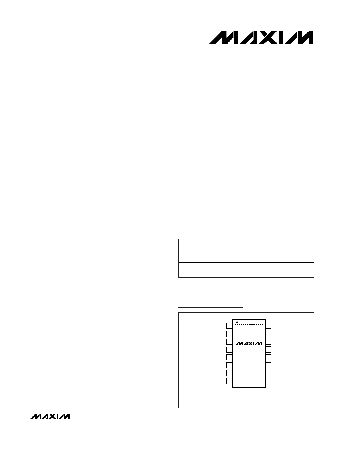
16
15
14
13
12
11
10
9
1
2
3
4
5
6
7
8
RT
REG5
IN
V
CC
NDRVA
NDRVB
PGND
AGND
CS
TOP VIEW
MAX5069
TSSOP-EP
SYNC(HYST*)
SCOMP
FB
DT
UVLO/EN
COMP
FLTINT
*MAX5069B/C.
Pin Configuration
Ordering Information
19-3175; Rev 0; 2/04
For pricing, delivery, and ordering information, please contact Maxim/Dallas Direct! at
1-888-629-4642, or visit Maxim’s website at www.maxim-ic.com.
*Future product—contact factory for availability.
**EP = Exposed pad.
PART TEMP RANGE PIN-PACKAGE
MAX5069AAUE*
16 TSSOP-EP**
MAX5069BAUE
16 TSSOP-EP**
MAX5069CAUE
16 TSSOP-EP**
MAX5069DAUE*
16 TSSOP-EP**
Selector Guide appears at end of data sheet.
-40°C to +125°C
-40°C to +125°C
-40°C to +125°C
-40°C to +125°C
Page 2
MAX5069
High-Frequency, Current-Mode PWM Controller
with Accurate Oscillator and Dual FET Drivers
2 _______________________________________________________________________________________
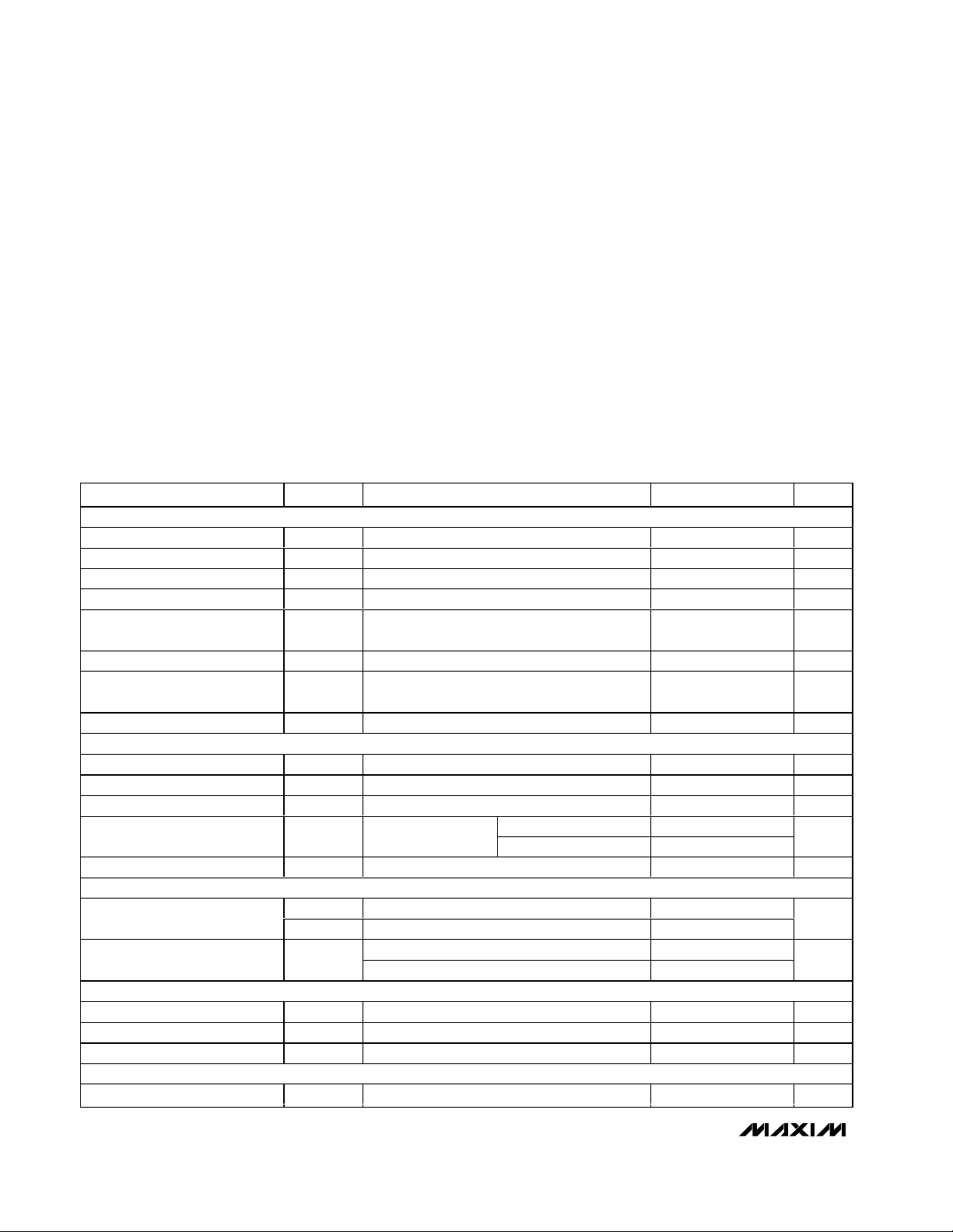
ABSOLUTE MAXIMUM RATINGS
ELECTRICAL CHARACTERISTICS
(V
IN
= +12V for the MAX5069C/D, VIN= +23.6V for the MAX5069A/B at startup, then reduces to +12V, CIN= C
REG5
= 0.1µF,
C
VCC
= 1µF, RRT= 100kΩ, NDRV_ = floating, TA= T
MIN
to T
MAX
, unless otherwise noted. Typical values are at TA= +25°C.) (Note 1)
Stresses beyond those listed under “Absolute Maximum Ratings” may cause permanent damage to the device. These are stress ratings only, and functional
operation of the device at these or any other conditions beyond those indicated in the operational sections of the specifications is not implied. Exposure to
absolute maximum rating conditions for extended periods may affect device reliability.
IN to PGND ............................................................-0.3V to +30V
IN to AGND.............................................................-0.3V to +30V
V
CC
to PGND..........................................................-0.3V to +13V
V
CC
to AGND..........................................................-0.3V to +13V
FB, COMP, CS, HYST, SYNC, REG5 to AGND ........-0.3V to +6V
UVLO/EN, RT, DT, SCOMP, FLTINT to AGND .........-0.3V to +6V
NDRVA, NDRVB to PGND..........................-0.3V to (V
CC
+ 0.3V)
AGND to PGND.....................................................-0.3V to +0.3V
Continuous Power Dissipation (T
A
= +70°C)
16-Pin TSSOP-EP (derate 21.3mW/°C above +70°C)...1702mW
Operating Temperature Range..........................-40°C to +125°C
Maximum Junction Temperature .....................................+150°C
Storage Temperature Range .............................-60°C to +150°C
Lead Temperature (soldering, 10s) .................................+300°C
PARAMETER
CONDITIONS
UNITS
UNDERVOLTAGE LOCKOUT/STARTUP
Bootstrap UVLO Wake-Up Level
V
SUVR
VIN rising, MAX5069A/B
V
Bootstrap UVLO Shutdown Level
V
SUVF
VIN falling, MAX5069A/B
V
UVLO/EN Wake-Up Threshold V
ULR2
UVLO/EN rising
V
UVLO/EN Shutdown Threshold V
ULF2
UVLO/EN falling
V
HYST FET On-Resistance
MAX5069B/C only, sinking 50mA,
V
UVLO/EN
= 0V
Ω
HYST FET Leakage Current I
LEAK_H
V
UVLO/EN
= 2V, V
HYST
= 5V 3 nA
IN Supply Current In
Undervoltage Lockout
I
START
VIN = +19V, V
UVLO/EN
< V
ULF2
90 µA
IN Range V
IN
V
INTERNAL SUPPLIES (VCC and REG5)
VCC Regulator Set Point V
CCSP
V
REG5 Output Voltage V
REG5IREG5
= 0 to 1mA
V
REG5 Short-Circuit Current Limit
mA
f
SW
= 1.25MHz 7
IN Supply Current After Startup I
IN
VIN = +24V
f
SW
= 100kHz 3
mA
Shutdown Supply Current I
VIN_SD
90 µA
GATE DRIVER (NDRVA, NDRVB)
)
NDRVA/NDRVB sinking 100mA 2 4
Driver Output Impedance
)
NDRVA/NDRVB sourcing 25mA 3 6
Ω
Sinking
Driver Peak Output Current I
NDRV
Sourcing
mA
PWM COMPARATOR
Comparator Offset Voltage
V
COMP
> V
CS
V
Comparator Propagation Delay
VCS = 0.1V
ns
Minimum On-Time
)
Includes t
CS_BLANK
ns
CURRENT-LIMIT COMPARATOR
Current-Limit Trip Threshold V
CS
mV
SYMBOL
R
D S ( ON ) _H
I
REG5_SC
Z
OUT(LOW
Z
OUT(HIGH
V
OS_PWM
t
PD_PWM
t
ON(MIN
V
MIN TYP MAX
19.68 21.6 23.60
9.05 9.74 10.43
1.205 1.230 1.255
10.8 24.0
= + 10.8V to + 24V , V
IN
sour ci ng 1µA to 25m A 7.0 10.5
C C
4.85 5.00 5.15
1.30 1.60 2.00
298 314 330
1.18
10
47
18
1000
650
40
110
Page 3
MAX5069
High-Frequency, Current-Mode PWM Controller
with Accurate Oscillator and Dual FET Drivers
_______________________________________________________________________________________ 3
PARAMETER
CONDITIONS
UNITS
CS Input Bias Current I
B_CL
VCS = 0V 0
µA
CS Blanking Time
ns
Propagation Delay from
Comparator Input to NDRV_
t
PD_CL
50mV overdrive
ns
IN CLAMP VOLTAGE
IN Clamp Voltage
IN sinking 2mA (Note 2)
V
ERROR AMPLIFIER (FB, COMP)
Voltage Gain A
V
R
COMP
= 100kΩ to AGND
dB
Unity-Gain Bandwidth BW
R
COMP
= 100kΩ to AGND,
C
LOAD
= 100pF to AGND
5
MHz
Phase Margin PM
R
COMP
= 100kΩ to AGND,
C
LOAD
= 100pF to AGND
D eg r ees
FB Input Offset Voltage V
OS_FB
3mV
High
COMP Clamp Voltage V
COMP
Low
V
Error-Amplifier Output Current I
COMP
Sinking or sourcing
mA
+25°C ≤ TA ≤ +125°C (Note 3)
Reference Voltage V
REF
-40°C ≤ TA ≤ +125°C (Note 3)
V
Input Bias Current I
B_EA
nA
COMP Short-Circuit Current
mA
THERMAL SHUTDOWN
Thermal-Shutdown Temperature
T
SD
°C
Thermal Hysteresis T
HYST
°C
OSCILLATOR SYNC INPUT (MAX5069A/D only)
SYNC High-Level Voltage
V
SYNC Low-Level Voltage
V
SYNC Input Bias Current
nA
Maximum SYNC Frequency f
SYNC
f
OSC
= 2.5MHz (Note 4)
MHz
SYNC High-Level Pulse Width
ns
SYNC Low-Level Pulse Width
ns
DIGITAL SOFT-START
Soft-Start Duration t
SS
(Note 5)
Cycles
Reference-Voltage Step V
STEP
mV
Reference-Voltage Steps During
Soft-Start
Steps
OSCILLATOR
Oscillator Frequency Range f
OSC
f
OSC
= (1011 / RRT)
kHz
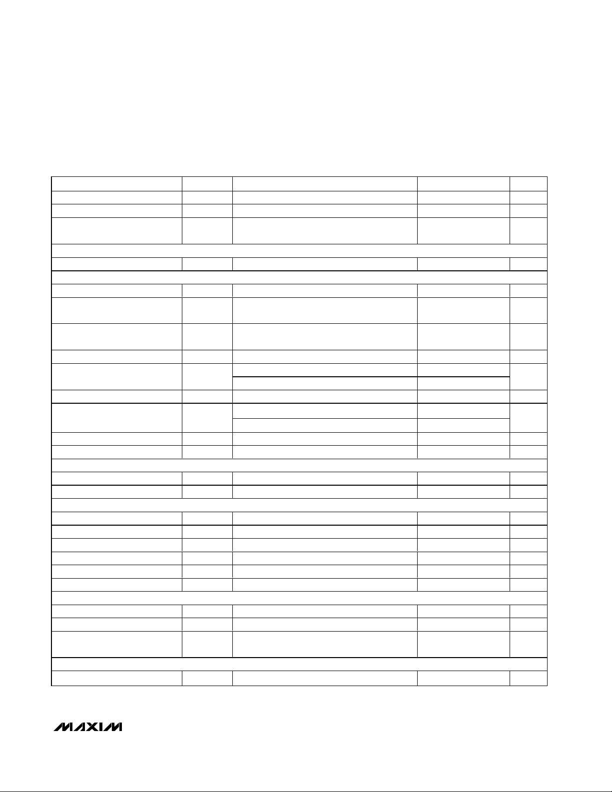
ELECTRICAL CHARACTERISTICS (continued)
(V
IN
= +12V for the MAX5069C/D, VIN= +23.6V for the MAX5069A/B at startup, then reduces to +12V, CIN= C
REG5
= 0.1µF,
C
VCC
= 1µF, RRT= 100kΩ, NDRV_ = floating, TA= T
MIN
to T
MAX
, unless otherwise noted. Typical values are at TA= +25°C.) (Note 1)
SYMBOL
t
CS_BLANK
V
IN_CLAMP
I
COMP_SC
V
V
I
t
SYNC_HI
t
SYNC_LO
IH_SYNC
IL_SYNC
B_SYNC
MIN TYP MAX
24.0 26.0 29.0
2.6 3.8
0.4 1.1
0.5
1.215 1.230 1.245
1.205 1.230 1.242
2.4
3.125
30
30
50 2500
70
40
80
65
100 300
12
+170
25
10
2047
9.7
127
+2
0.4
Page 4
MAX5069
High-Frequency, Current-Mode PWM Controller
with Accurate Oscillator and Dual FET Drivers
4 _______________________________________________________________________________________
Note 1: The MAX5069 is 100% tested at TA= +25°C. All limits over temperature are guaranteed by design.
Note 2: The MAX5069A/B are intended for use in universal-input power supplies. The internal clamp circuit is used to prevent the
bootstrap capacitor (C1 in Figure 1) from charging to a voltage beyond the absolute maximum rating of the device when
UVLO/EN is low. The maximum current to V
IN
(hence to clamp) when UVLO is low (device is in shutdown) must be externally limited to 2mA. Clamp currents higher than 2mA may result in clamp voltages higher than 30V, thus exceeding the
absolute maximum rating for V
IN
. For the MAX5069C/D, do not exceed the 24V maximum operating voltage of the device.
Note 3: Reference voltage (V
REF
) is measured with FB connected to COMP (see the Functional Diagram).
Note 4: The SYNC frequency must be at least 25% higher than the programmed oscillator frequency.
Note 5: The internal oscillator clock cycle.
PARAMETER
CONDITIONS
UNITS
NDRV_ Switching Frequency f
SW
fSW = 1011 / (2 x RRT)25
kHz
RT Voltage V
RT
40kΩ < R
RT
< 500kΩ 2.0 V
TA = +25°C
-4 +4
Oscillator Accuracy
T
A
= -40°C to +125°C
-6 +6
%
Maximum Duty Cycle D
MAX
DT connected to REG5
%
DEAD-TIME CONTROL (DT)
Dead Time t
DT
RDT = 24.9kΩ 60 ns
Dead-Time Disable Voltage
V
REG5
V
Dead-Time Regulation Voltage V
DT
V
INTEGRATING FAULT PROTECTION (FLTINT)
FLTINT Source Current I
FLTINT
V
FLTINT
= 0V 60 µA
FLTINT Shutdown Threshold
V
FLTINT
rising 2.8 V
FLTINT Restart Threshold
V
FLTINT
falling 1.6 V
SLOPE COMPENSATION
Slope Compensation V
SLOPE
C
SLOPE
= 100pf, RT = 110kΩ 15
mV/µs
Slope-Compensation Range
090
mV/µs
Slope-Compensation Voltage
Range
V
SCOMP
0 2.7 V
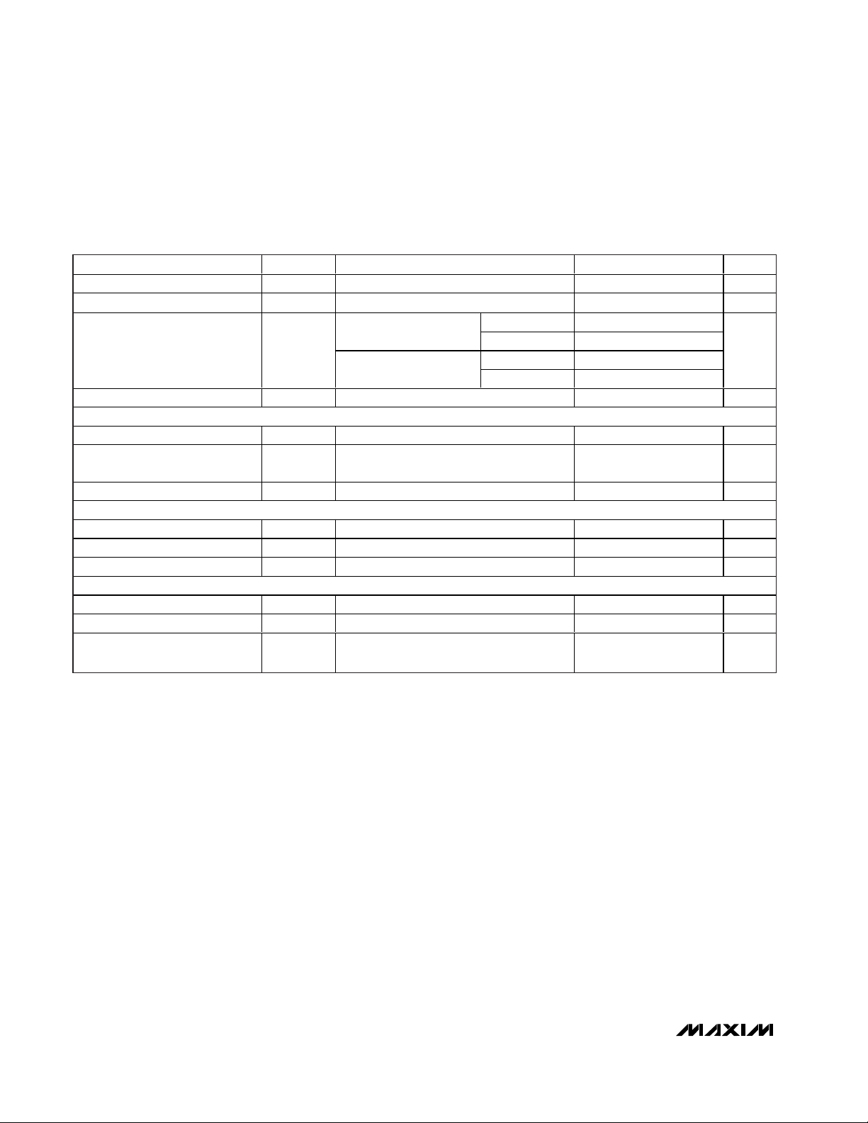
ELECTRICAL CHARACTERISTICS (continued)
(V
IN
= +12V for the MAX5069C/D, VIN= +23.6V for the MAX5069A/B at startup, then reduces to +12V, CIN= C
REG5
= 0.1µF,
C
VCC
= 1µF, RRT= 100kΩ, NDRV_ = floating, TA= T
MIN
to T
MAX
, unless otherwise noted. Typical values are at TA= +25°C.) (Note 1)
SYMBOL
V
DT_DISABLE
V
FLTINT_SD
V
FLTINT_RS
MIN TYP MAX
f
≤ 500kHz -2.5 +2.5
OSC
f
> 500kHz
OSC
f
≤ 500kHz -4.5 +4.5
OSC
f
> 500kHz
OSC
100
0.5V
1.23
1250
V
SLOPER
Page 5
MAX5069
High-Frequency, Current-Mode PWM Controller
with Accurate Oscillator and Dual FET Drivers
_______________________________________________________________________________________ 5
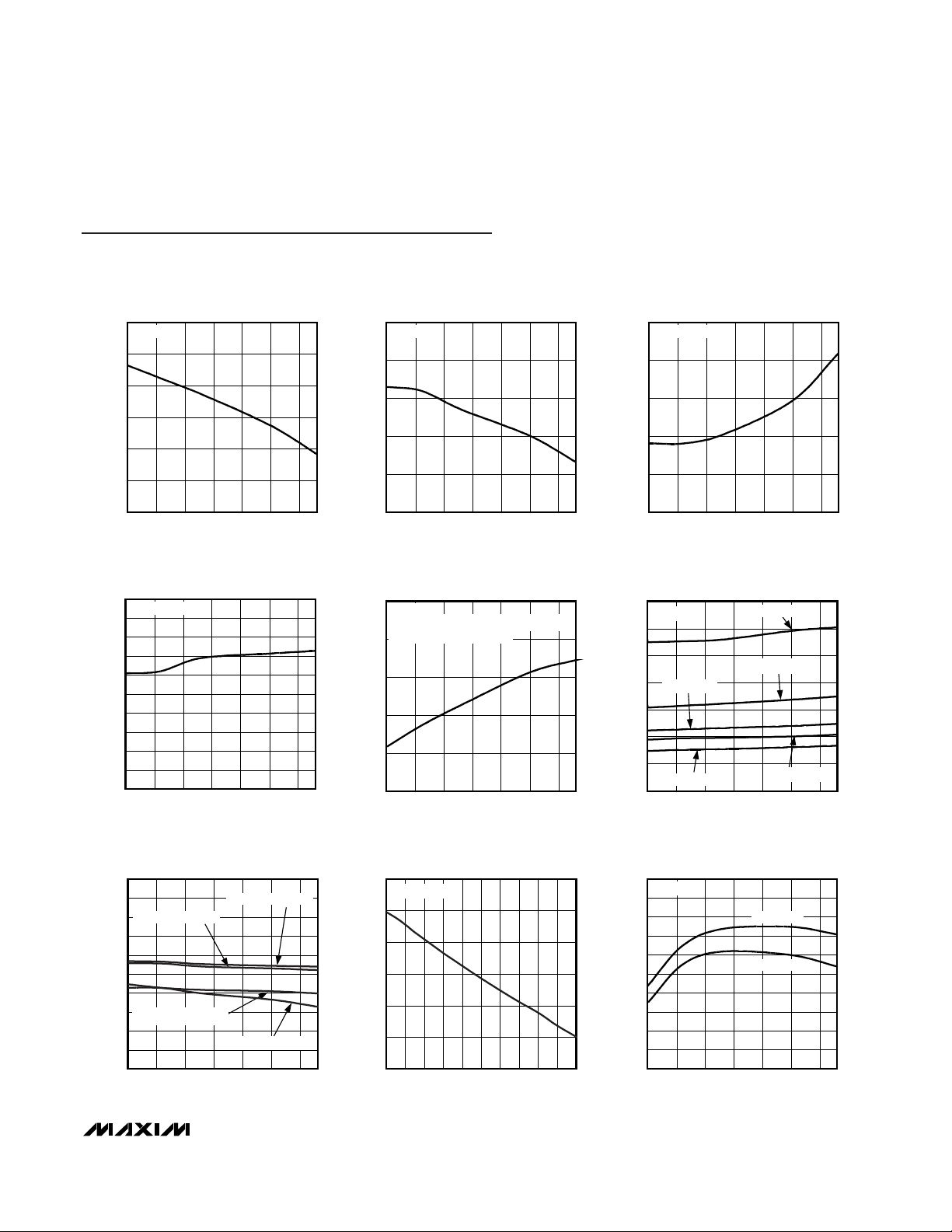
21.0
21.2
21.1
21.4
21.3
21.5
21.6
-40 35 60-15 10 85 110
BOOTSTRAP UVLO WAKE-UP LEVEL
vs. TEMPERATURE
MAX5069 toc01
TEMPERATURE (°C)
V
IN
(V)
MAX5069A/B
9.5
9.6
9.8
9.7
9.9
10.0
-40 35 60-15 10 85 110
BOOTSTRAP UVLO SHUTDOWN LEVEL
vs. TEMPERATURE
MAX5069 toc02
TEMPERATURE (°C)
V
IN
(V)
MAX5069A/B
1.220
1.225
1.235
1.230
1.240
1.245
-40 35 60-15 10 85 110
UVLO/EN WAKE-UP THRESHOLD
vs. TEMPERATURE
MAX5069 toc03
TEMPERATURE (°C)
UVLO/EN
(V)
UVLO/EN RISING
1.10
1.19
1.18
1.17
1.16
1.15
1.14
1.13
1.12
1.11
1.20
-40 35 60-15 10 85 110
UVLO/EN SHUTDOWN THRESHOLD
vs. TEMPERATURE
MAX5069 toc04
TEMPERATURE (°C)
UVLO/EN
(V)
UVLO/EN FALLING
40
44
52
48
56
60
-40 35 60-15 10 85 110
V
IN
SUPPLY CURRENT IN UNDERVOLTAGE
LOCKOUT vs. TEMPERATURE
MAX5069 toc05
TEMPERATURE (°C)
I
START
(µA)
V
IN
= 19V
WHEN IN BOOTSTRAP UVLO (MAX5069A/B)
UVLO/EN (MAX5069C/D) IS LOW
VIN SUPPLY CURRENT AFTER STARTUP
vs. TEMPERATURE
MAX5069 toc06
TEMPERATURE (°C)
I
IN
(mA)
85603510-15
3
2
4
6
5
7
8
1
-40 110
VIN = 24V
fSW = 1.25MHz
fSW = 50kHz
fSW = 500kHz
fSW = 100kHz
fSW = 250kHz
VCC vs. TEMPERATURE
MAX5069 toc07
TEMPERATURE (°C)
V
CC
(V)
85603510-15
7.6
7.3
8.2
7.9
8.8
8.5
9.4
9.1
9.7
10.0
7.0
-40 110
VIN = 19V, IIN = 25mA
VIN = 19V, IIN = 10mA
VIN = 10.8V, IIN = 10mA
VIN = 10.8V, IIN = 25mA
REG5 OUTPUT VOLTAGE
vs. OUTPUT CURRENT
MAX5069 toc08
OUTPUT CURRENT (mA)
REG5 (V)
1.81.61.41.21.00.80.60.40.2
4.955
4.960
4.965
4.970
4.975
4.980
4.950
02.0
RRT = 100kΩ
4.90
4.99
4.98
4.97
4.96
4.95
4.94
4.93
4.92
4.91
5.00
-40 35 60-15 10 85 110
REG5 vs. TEMPERATURE
MAX5069 toc09
TEMPERATURE (°C)
REG5 (V)
V
IN
= 10.8V
100µA LOAD
1mA LOAD
Typical Operating Characteristics
(VIN= +23.6V for MAX5069A/B at startup, then reduces to +12V, V
IN
= +12V for the MAX5069C/D, CIN= C
REG5
= 0.1µF, C
VCC
= 1µF,
RRT= 100kΩ, NDRV_ = floating, VFB= 0V, V
COMP
= floating, VCS= 0V, TA= +25°C, unless otherwise noted.)
Page 6
MAX5069
High-Frequency, Current-Mode PWM Controller
with Accurate Oscillator and Dual FET Drivers
6 _______________________________________________________________________________________
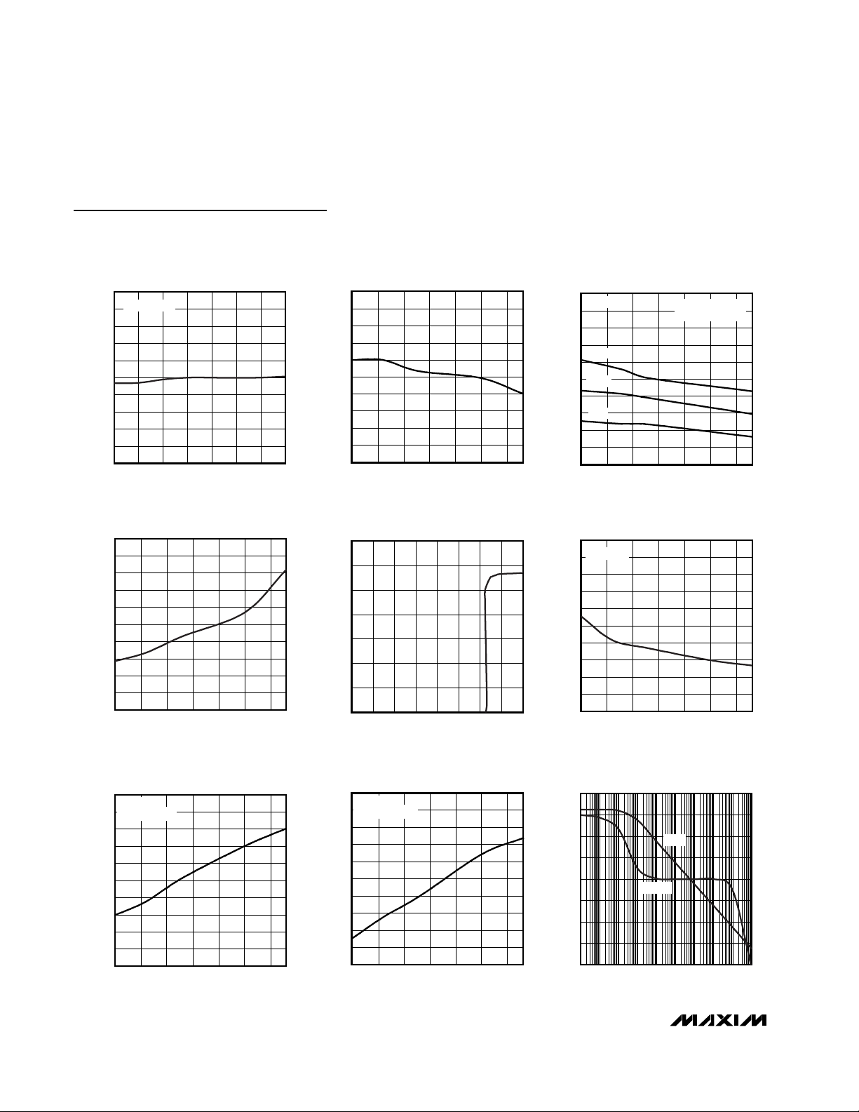
Typical Operating Characteristics (continued)
(VIN= +23.6V for MAX5069A/B at startup, then reduces to +12V, V
IN
= +12V for the MAX5069C/D, CIN= C
REG5
= 0.1µF, C
VCC
= 1µF,
RRT= 100kΩ, NDRV_ = floating, VFB= 0V, V
COMP
= floating, VCS= 0V, TA= +25°C, unless otherwise noted.)
REG5 OUTPUT VOLTAGE vs. V
IN
MAX5069 toc10
VIN (V)
REG5 (V)
222016 18141210 24
4.976
4.977
4.978
4.979
4.980
4.981
4.982
4.983
4.984
4.985
4.975
I
REG5
= 100µA
CS TRIP THRESHOLD
vs. TEMPERATURE
MAX5069 toc11
TEMPERATURE (°C)
CS TRIP THRESHOLD (mV)
110
85603510-15
306
303
309
315
312
321
318
327
324
330
300
-40
SWITCHING FREQUENCY
vs. TEMPERATURE
MAX5069 toc12
TEMPERATURE (°C)
SWITCHING FREQUENCY (kHz)
110
856035-15
10
490
485
495
505
500
515
510
525
520
530
480
-40
fSW = 500kHz
TOTAL NUMBER OF
DEVICES = 200
MEAN
-3σ
+3σ
PROPAGATION DELAY FROM CS COMPARATOR
INPUT TO NDRV vs. TEMPERATURE
MAX5069 toc13
TEMPERATURE (°C)
PROPAGATION DELAY (ns)
1108535 6010-15
32
34
36
38
40
42
44
46
48
50
30
-40
INPUT CURRENT
vs. INPUT CLAMP VOLTAGE
MAX5069 toc14
INPUT CLAMP VOLTAGE (V)
INPUT CURRENT (mA)
27.525.022.520.017.515.012.5
2
4
6
8
10
12
14
0
10.0 30.0
INPUT CLAMP VOLTAGE
vs. TEMPERATURE
MAX5069 toc15
TEMPERATURE (°C)
INPUT CLAMP VOLTAGE (V)
1108535 6010-15
25.2
25.4
25.6
25.8
26.0
26.2
26.4
26.6
26.8
27.0
25.0
-40
I
SINK
= 2mA
1.0
2.8
2.6
2.4
2.2
2.0
1.8
1.6
1.4
1.2
3.0
-40 35 60-15 10 85 110
NDRVA/NDRVB OUTPUT IMPEDANCE
vs. TEMPERATURE
MAX5069 toc16
TEMPERATURE (°C)
R
ON
(Ω)
V
IN
= 24V
SINKING 100mA
2.0
3.8
3.6
3.4
3.2
3.0
2.8
2.6
2.4
2.2
4.0
-40 35 60-15 10 85 110
NDRVA/NDRVB OUTPUT IMPEDANCE
vs. TEMPERATURE
MAX5069 toc17
TEMPERATURE (°C)
R
ON
(Ω)
V
IN
= 24V
SOURCING 25mA
ERROR AMPLIFIER OPEN-LOOP GAIN
AND PHASE vs. FREQUENCY
MAX5069 toc18
FREQUENCY (Hz)
GAIN (dB)
PHASE (DEGREES)
10M10 100k1k
-20
0
20
40
60
80
100
120
-40
-180
-150
-120
-90
-60
-30
0
30
-210
0.1
GAIN
PHASE
Page 7

MAX5069
High-Frequency, Current-Mode PWM Controller
with Accurate Oscillator and Dual FET Drivers
_______________________________________________________________________________________ 7
62.0
62.9
62.8
62.7
62.6
62.5
62.4
62.3
62.2
62.1
63.0
-40 35 60-15 10 85 110
FLTINT CURRENT vs. TEMPERATURE
MAX5069 toc19
TEMPERATURE (°C)
FLTINT CURRENT
(µA)
8.0
12.5
12.0
11.5
11.0
10.5
10.0
9.5
9.0
8.5
13.0
-40 35 60-15 10 85 110
HYST R
ON
vs. TEMPERATURE
MAX5069 toc20
TEMPERATURE (°C)
R
ON
(Ω)
V
IN
= 24V
SINKING 50mA
0.01
0.1
1
2
0.03 0.1 1 2
NDRVA SWITCHING FREQUENCY (f
SW)
vs. R
RT
MAX5069 toc21
R
RT
(MΩ)
f
SW
(MHz)
NDRV SWITCHING FREQUENCY
vs. TEMPERATURE
MAX5069 toc22
TEMPERATURE (°C)
NDRV SWITCHING FREQUENCY (kHz)
1108535 6010-15
48.4
48.8
49.2
49.6
50.0
50.4
50.8
51.2
51.6
52.0
48.0
-40
fSW = 50kHz
NDRV SWITCHING FREQUENCY
vs. TEMPERATURE
MAX5069 toc23
TEMPERATURE (°C)
NDRV SWITCHING FREQUENCY (kHz)
100
125
75
50
250-25
497
496
498
500
499
502
501
504
503
505
495
-50
fSW = 500kHz
fSW = 500kHz
DEAD TIME vs. TEMPERATURE
MAX5069 toc25
TEMPERATURE (°C)
TIME (ns)
11085603510-15
45
50
55
60
65
70
40
-40
VIN = 24V
R
DT
= 24.9kΩ
R
RT
= 100kΩ
NDRV SWITCHING FREQUENCY
vs. TEMPERATURE
MAX5069 toc24
TEMPERATURE (°C)
NDRV SWITCHING FREQUENCY (kHz)
110
85
60
3510-15
1.15
1.20
1.25
1.30
1.35
1.40
1.10
-40
fSW = 1.25MHz
DEAD TIME vs. R
DT
MAX5069 toc26
RDT (kΩ)
TIME (ns)
10
20
40
60
80
100
120
140
160
180
200
0
1100
Typical Operating Characteristics (continued)
(VIN= +23.6V for MAX5069A/B at startup, then reduces to +12V, V
IN
= +12V for the MAX5069C/D, CIN= C
REG5
= 0.1µF, C
VCC
= 1µF,
RRT= 100kΩ, NDRV_ = floating, VFB= 0V, V
COMP
= floating, VCS= 0V, TA= +25°C, unless otherwise noted.)
Page 8

MAX5069
High-Frequency, Current-Mode PWM Controller
with Accurate Oscillator and Dual FET Drivers
8 _______________________________________________________________________________________
Pin Description
PIN
MAX5069A
MAX5069D
NAME FUNCTION
11RT
Oscillator-Timing Resistor. Connect a resistor from RT to AGND to set the internal oscillator
frequency.
2—SYNC External-Clock Sync Input. Connect SYNC to AGND when not using an external clock.
—2HYST Hysteresis Input
33
Slope-Compensation Capacitor Connection
44DT
Dead-Time Resistor Connection. Connect a resistor from DT to AGND to program the
output dead time. Connect to REG5 for NDRVA and NDRVB maximum 50% duty cycle.
55
Externally Programmable Undervoltage Lockout. UVLO/EN programs the input start
voltage. Connect UVLO/EN to AGND to disable the output.
66FB Error-Amplifier Inverting Input
77COMP Error-Amplifier Output
88
Fault-Integration Input. A capacitor connected to FLTINT charges with an internal 60µA
current source during persistent current-limit faults. Switching terminates when V
FLTINT
is
2.8V. An external resistor connected in parallel discharges the capacitor. Switching
resumes when V
FLTINT
drops to 1.6V.
99CS Current-Sense Resistor Connection
10 10 AGND Analog Ground. Connect to PGND.
11 11 PGND Power Ground. Connect to AGND through a ground plane.
12 12
G ate- D r i ver O utp ut B. C onnect N D RV B to the g ate of the exter nal N - channel FE T.
13 13
Gate-Driver Output A. Connect NDRVA to the gate of the external N-channel FET.
14 14 V
CC
9V Linear-Regulator Output. Decouple VCC with a minimum 1µF ceramic capacitor to
AGND; also internally connected to the FET drivers.
15 15 IN
Power-Supply Input. IN provides power for all internal circuitry except the gate driver.
Decouple IN with 0.1µF to AGND (see the Typical Operating Circuit).
16 16 REG5 5V Linear-Regulator Output. Decouple REG5 to AGND with 0.1µF ceramic capacitor.
EP EP PAD Exposed Paddle. Connect to GND.
MAX5069B
MAX5069C
SCOMP
UVLO/EN
FLTINT
NDRVB
NDRVA
Page 9

Detailed Description
The MAX5069 is a current-mode, dual MOSFET driver,
PWM controller designed for isolated and nonisolated
push-pull or half-/full-bridge power-supply applications.
A bootstrap UVLO with a programmable hysteresis,
very low startup, and low operating current result in
high-efficiency universal-input power supplies. In addition to the internal bootstrap UVLO, the device also
offers programmable input startup and turn-off voltages, programmed through the UVLO/EN pin.
The MAX5069 includes a cycle-by-cycle current limit
that turns off the gate drive to the external MOSFET
during an overcurrent condition. The MAX5069 integrating fault protection reduces average power dissipation
during persistent fault conditions (see the Integrating
Fault Protection section).
The MAX5069 features a very accurate, wide-range,
programmable oscillator that simplifies and optimizes
the design of the magnetics. The MAX5069A/B are well
suited for universal-input (rectified 85VAC to 265VAC)
or telecom (-36VDC to -72VDC) power supplies. The
MAX5069C/D are well suited for low-input voltage
(10.8VDC to 24VDC) power supplies.
The MAX5069 high-frequency, universal input,
offline/telecom, current-mode PWM controller integrates
all the building blocks necessary for implementing ACDC and DC-DC fixed-frequency power supplies. Pushpull and half-/full-bridge isolated or nonisolated power
supplies are easily constructed using either primary- or
secondary-side regulation. Current-mode control with
leading-edge blanking simplifies control-loop design
and the programmable slope compensation stabilizes
the current loop when operating both FET drivers at a
combined 100% duty cycle.
An input UVLO programs the input-supply startup voltage and ensures proper operation during brownout conditions. An external voltage-divider programs the supply
startup voltage. The MAX5069B/C feature a programmable UVLO hysteresis. The MAX5069A/B feature an additional internal bootstrap UVLO with large hysteresis that
requires a minimum startup voltage of 23.6V. The
MAX5069A/D start up from a minimum voltage of 10.8V.
Internal digital soft-start reduces output-voltage overshoot at startup.
A single external resistor programs the switching frequency of each MOSFET driver from 25kHz to
1.25MHz. The MAX5069A/D provide a SYNC input for
synchronization to an external clock. The maximum FET
driver duty cycle for each driver is limited to 50%.
Programmable dead time allows additional flexibility in
optimizing magnetic design and overcoming parasitic
effects. Integrating fault protection ignores transient
overcurrent conditions for a set length of time. The
length of time is programmed by an external capacitor.
The internal thermal-shutdown circuit protects the
device should the junction temperature exceed
+170°C.
Power supplies designed with the MAX5069A/B use a
high-value startup resistor, R1, which charges a reservoir capacitor, C1 (Figure 1). During this initial period,
while the voltage is less than the internal bootstrap
UVLO threshold, the device typically consumes only
47µA of quiescent current. This low startup current and
the large bootstrap UVLO hysteresis help to minimize
the power dissipation across R1 even at the high end of
the universal AC input voltage (265VAC).
The MAX5069 includes a cycle-by-cycle current limit
that turns off the gates to both external MOSFETs during an overcurrent condition. When using the
MAX5069A/B in the bootstrap mode (if the power-supply output is shorted), the tertiary winding voltage
drops below the 9.74V threshold, causing the UVLO to
turn off the gate to the external power MOSFETs. This
reinitiates a startup sequence with soft-start.
Current-Mode Control
The MAX5069 offers a current-mode control operation
feature, such as leading-edge blanking with a dual
internal path that only blanks the sensed current signal
applied to the input of the PWM controller. The currentlimit comparator monitors CS at all times and provides
cycle-by-cycle current limit without being blanked. The
leading-edge blanking of the CS signal prevents the
PWM comparator from prematurely terminating the on
cycle. The CS signal contains a leading-edge spike
that results from the MOSFET’s gate charge current,
and the capacitive and diode reverse-recovery current
of the power circuit. Since this leading-edge spike is
normally lower than the current-limit comparator threshold, current limiting is provided under all conditions.
Use the MAX5069 in push-pull and half-/full-bridge applications where a large duty cycle is desired. The large
duty cycle results in much lower operating primary RMS
currents through the MOSFET switches, and in most
cases it results in a smaller inductor and output filter
capacitor. The MAX5069 adjusted slope compensation
allows for easy stabilization of the inner current loop.
MAX5069
High-Frequency, Current-Mode PWM Controller
with Accurate Oscillator and Dual FET Drivers
_______________________________________________________________________________________ 9
Page 10

MAX5069
Undervoltage Lockout
The MAX5069 features an input voltage UVLO/EN function to enable the PWM controller before any operation
can begin. The MAX5069A/D shut down if the voltage
at UVLO/EN falls below its 1.18V threshold. The
MAX5069B/C also incorporate a UVLO hysteresis input
to set the desired turn-off voltage.
MAX5069A/D UVLO Adjustment
The MAX5069A/D have an input voltage UVLO/EN with
a 1.231V threshold. Before any operation can commence, the UVLO/EN voltage must exceed the 1.231V
threshold. The UVLO circuit keeps the PWM comparator, ILIM comparator, oscillator, and output drivers shutdown to reduce current consumption (see the
Functional Diagram).
Calculate R6 in Figure 2 by using the following formula:
where V
ULR2
is the UVLO/EN’s 1.231V rising threshold
and VONis the desired startup voltage. Choose an R7
value in the 20kΩ range.
After a successful startup, the MAX5069A/D shut down
if the voltage at UVLO/EN drops below its 1.18V falling threshold.
MAX5069B/C UVLO with
Programmable Hysteresis
In addition to programmable undervoltage lockout during startup, the MAX5069B/C incorporate a UVLO/EN
R
V
V
R
ON
ULR
617
2
=
×
−
High-Frequency, Current-Mode PWM Controller
with Accurate Oscillator and Dual FET Drivers
10 ______________________________________________________________________________________
MAX5069B
IN
NDRVA
NDRVB
HYST
UVLO/EN
CS
COMP
V
CC
AGND PGND
REG5
RT
FB
DT
FLTINT
R1
C1
Q1
Q2
V
IN
C2
C3
C4
R3
R4
R9
R2
R8
V
OUT
SCOMP
C5
C7
D1
D3
D2
R5
C6
R10
R6
R
HYST
R7
Figure 1. Nonisolated Power Supply with Programmable Input Supply Voltage
Page 11

hysteresis that allows the user to set a voltage (V
OFF
) to
disable the controller (see Figure 3).
At the beginning of the startup sequence, UVLO/EN is
below the 1.23V threshold, and Q1 turns on connecting
R
HYST
to GND (Figure 4). Once the UVLO 1.23V threshold is crossed, Q1 turns off, resulting in the series combination of R6, R
HYST
, and R7, placing the MAX5069 in
normal operating condition.
Calculate the turn-on voltage (VON) by using the fol-
lowing formula:
where V
ULR2
is the UVLO/EN’s 1.23V rising threshold.
Choose an R
HYST
value in the 20kΩ range.
The MAX5069 turns off when the MAX5069 UVLO/EN
falls below the 1.18V falling threshold. The turn-off voltage (V
OFF
) is then defined as:
where V
ULF2
is the 1.18V UVLO/EN falling threshold.
Bootstrap Undervoltage Lockout
(MAX5069A/B)
In addition to the externally programmable UVLO function offered by the MAX5069, the MAX5069A/B feature
an additional internal bootstrap UVLO for use in highvoltage power supplies (see the Functional Diagram).
This allows the device to bootstrap itself during initial
power-up. The MAX5069A/B start when VINexceeds
the bootstrap UVLO threshold of 23.6V.
During startup, the UVLO circuit keeps the PWM comparator, ILIM comparator, oscillator, and output drivers
shut down to reduce current consumption. Once V
IN
reaches 23.6V, the UVLO circuit turns on both the PWM
and ILIM comparators, as well as the oscillator, and
allows the output driver to switch. If V
IN
drops below
9.7V, the UVLO circuit shuts down the PWM comparator, ILIM comparator, oscillator, and output drivers,
returning the MAX5069A/B to the startup mode.
RR
V
V
R
OFF
ULF
HYST
76 1
2
/ =
−−
R
V
V
R
ON
ULR
HYST
61
2
=
×
−
MAX5069
High-Frequency, Current-Mode PWM Controller
with Accurate Oscillator and Dual FET Drivers
______________________________________________________________________________________ 11
MAX5069A/D
1.23V
1.18V
UVLO/EN
R7
R6
V
IN
Figure 2. Setting the MAX5069A/D Undervoltage Lockout
Threshold
V
HYST
= VON - V
OFF
V
OFF
V
ON
Figure 3. MAX5069 Hysteresis
MAX5069B/C
1.23V
1.18V
UVLO/EN
HYST
R
HYST
R6
R7
V
IN
Q1
Figure 4. Setting the MAX5069B/C Turn-On/Turn-Off Voltages
Page 12

MAX5069
MAX5069A/B Startup Operation
Normally, VINis derived from the tertiary winding of the
transformer. However, at startup there is no energy
delivered through the transformer; hence, a special
bootstrap sequence is required. Figure 5 shows the
voltages on VINand VCCduring startup. Initially, both
VINand VCCare 0V. After the input voltage is applied,
C1 charges through the startup resistor, R1, to an intermediate voltage (see Figure 1). At this point, the internal regulator begins charging C3 (see Figure 5). Only
47µA of the current supplied by R1 is used by the
MAX5069A/B. The remaining input current charges C1
and C3. The charging of C3 stops when the VCCvoltage reaches approximately 9.5V. The voltage across
C1 continues rising until it reaches the wake-up level of
23.6V. Once VINexceeds the bootstrap UVLO threshold, NDRVA/NDRVB begin switching the MOSFETs and
energy is transferred to the secondary and tertiary outputs. If the voltage on the tertiary output builds to higher than 9.74V (the bootstrap UVLO lower threshold),
startup ends and sustained operation commences.
If VINdrops below 9.74V before startup is complete, the
device goes back to low-current UVLO. If this occurs,
increase the value of C1 to store enough energy to
allow for the voltage at the tertiary winding to build up.
Startup Time Considerations for
Power Supplies Using the MAX5069A/B
The VINbypass capacitor, C1, supplies current immediately after wakeup (see Figure 1). The size of C1 and
the connection configuration of the tertiary winding
determine the number of cycles available for startup.
Large values of C1 increase the startup time and also
supply extra gate charge for more cycles during initial
startup. If the value of C1 is too small, VINdrops below
9.74V because NDRVA/NDRVB do not have enough
time to switch and build up sufficient voltage across the
tertiary output that powers the device. The device goes
back into UVLO and does not start. Use low-leakage
capacitors for C1 and C3.
Generally, offline power supplies keep typical startup
times to less than 500ms, even in low-line conditions
(85VAC input for universal offline applications or
36VDC for telecom applications). Size the startup resistor, R1, to supply both the maximum startup bias of the
device (90µA) and the charging current for C1 and C3.
The bypass capacitor, C3, must charge to 9.5V, and
C1 must charge to 24V, within the desired time period
of 500ms. Because of the internal soft-start time of the
MAX5069, C1 must store enough charge to deliver current to the device for at least 2047 oscillator clock
cycles. To calculate the approximate amount of capacitance required, use the following formula:
where I
IN
is the MAX5069’s internal supply current after
startup (3.3mA, typ), Q
gtot
is the total gate charge for
Q1 and Q2, fSWis the MAX5069’s programmed output
switching frequency, V
HYST
is the bootstrap UVLO hysteresis (12V), and tssis the internal soft-start time (2047
clock cycles x 1 / f
OSC
).
Example: I
g
= (16nC) (250kHz) ≅ 4mA
f
OSC
= 500kHz
t
SS
= 2047 x (1 / f
OSC
) = 4.1ms
Use a 4.7µF ceramic capacitor for C1.
Assuming C1 > C3, calculate the value of R1 as follows:
where V
SUVR
is the bootstrap UVLO wakeup level
(23.6V max), V
IN(MIN)
is the minimum input supply volt-
age for the application (36V for telecom), and I
START
is
the VINsupply current at startup (90µA, max).
I
VC
ms
R
VxV
II
C
SUVR
IN MIN SUVR
C START
1
1
1
500
1
05
.
()
≅
×
≅
−
+
C
mA mA ms
V
F1
33 4 41
12
25
(. ) (. )
.=
+
=µ
IQxf
C
IIxt
V
g gtot SW
IN g SS
HYST
( )
=
=+1
High-Frequency, Current-Mode PWM Controller
with Accurate Oscillator and Dual FET Drivers
12 ______________________________________________________________________________________
100ms/div
MAX5069
V
IN
PIN
V
CC
2V/div
0V
5V/div
Figure 5. VINand VCCDuring Startup When Using the
MAX5069 in Bootstrapped Mode (See Figure 1)
Page 13

For example: To minimize power loss on this resistor, choose a high-
er value for R1 than the one calculated above (if a
longer startup time can be tolerated).
The above startup method applies to a circuit similar to
the one shown in Figure 1. In this circuit, the tertiary
winding has the same phase as the secondary windings. Thus, the voltage on the tertiary winding at any
given time is proportional to the output voltage. The
minimum discharge time of C1 from 22V to 10V must
be greater than the soft-start time (t
SS
).
I
Vx F
ms
A
R
VV
AA
k
C1
24 4 7
500
225
1
36 12
225 90
76
.
==
≅
+
=
−
µ
µ
µµ
Ω
MAX5069
High-Frequency, Current-Mode PWM Controller
with Accurate Oscillator and Dual FET Drivers
______________________________________________________________________________________ 13
IN
UVLO/EN
NDRVA
NDRVB
V
CC
FB
CS
PGNDAGND
REG5
FLTINT
RT
DT
SCOMP
COMP
HYST
R1
C1
C2
C3
C4
R2
R3
R4
C5
R6
R7
R5
R8
V
OUT
V
IN
Q2
Q1
C6
R
HYST
C7
C8
R9
C10
MAX8515
R13
R14
PS2913
V
CC
R10
R11
R12
MAX5069B
Figure 6. Secondary-Side, Regulated, Isolated Power Supply
Page 14

MAX5069
Oscillator/Switching Frequency
Use an external resistor at RT to program the MAX5069
internal oscillator frequency from 50kHz to 2.5MHz. The
MAX5069 NDRVA/NDRVB switching frequency is one
half of the programmed oscillator frequency with a
maximum 50% duty cycle.
Use the following formula to calculate the internal oscillator frequency:
where f
OSC
is the oscillator frequency and RRTis a
resistor connected from RT to AGND.
Choose the appropriate resistor at RT to calculate the
desired switching frequency (fSW):
For the maximum 50% duty cycle at NDRVA/NDRVB,
connect DT to REG5.
Dual N-Channel MOSFET Switch Driver
The MAX5069 drives two external N-channel MOSFETs
in push-pull isolated power supplies. Each MOSFET
driver operates with a maximum 50% duty cycle. The
NDRV_ outputs are supplied by the internal regulator
(VCC), which is internally set to approximately 9.5V. For
the universal input voltage range, the MOSFETs used
must be able to withstand at least twice the DC level of
the high-line input voltage. Both NDRVA and NDRVB
can source and sink in excess of 650mA and 1000mA
peak current, respectively.
Dead-Time Control
In typical push-pull designs, it is desirable to add some
extra delay between the turning off of one MOSFET and
the turning on of the next MOSFET (Figure 7). The extra
time ensures that the first MOSFET is fully off when the
other MOSFET starts to turn on. This prevents both
MOSFETs from being on simultaneously, thus avoiding
shorting out the transformer’s primary. The MAX5069
allows the dead-time delay required to turn on the
NDRVB FET after the NDRVA FET turns off. The dead
time can be programmed to a minimum of 30ns to 1 / (0.5
x fSW). Connect a resistor between DT and AGND to set
the desired dead time. Calculate the dead time using the
following formula:
where RDTis in kΩ and the dead time is in ns.
External Synchronization (MAX5069A/D)
The MAX5069A/D can be synchronized using an external clock at the SYNC input. For proper frequency synchronization, the SYNC’s input frequency must be at
least 25% higher than the MAX5069A/D programmed
internal oscillator frequency. Connect SYNC to AGND
when not using an external clock.
Integrating Fault Protection
The integrating fault-protection feature allows transient
overcurrent conditions to be ignored for a programmable amount of time, giving the power supply time to
behave like a current source to the load. For example,
this can occur under load-current transients when the
control loop requests maximum current to keep the output voltage from going out of regulation. Program the
fault-integration time by connecting an external suitably
sized capacitor to the FLTINT. Under sustained overcurrent faults, the voltage across this capacitor ramps
up towards the FLTINT shutdown threshold (typically
2.8V). Once the threshold is reached, the power supply
shuts down. A high-value bleed resistor connected in
parallel with the FLTINT capacitor allows it to discharge
towards the restart threshold (typically 1.6V). Once this
threshold is reached, the supply restarts with a new
soft-start cycle.
Dead time R ns
DT
. ()=×
60
29 4
RT
SW
R
f
=
10
2
11
f
R
osc
RT
=
10
11
High-Frequency, Current-Mode PWM Controller
with Accurate Oscillator and Dual FET Drivers
14 ______________________________________________________________________________________
DEAD TIME
NDRVA
PWM
PWM
<50%
<50%
NDRVB
t
DT
Figure 7. MAX5069 Dead-Time Timing Diagram
MAX5069A/D
AGND
RT
SYNC
Figure 8. External Synchronization of the MAX5069A/D
Page 15

Note that cycle-by-cycle current limiting is provided at
all times by CS with a threshold of 314mV (typ). The
fault-integration circuit forces a 60µA current onto
FLTINT each time that the current-limit comparator is
tripped (see the Functional Diagram). Use the following
formula to calculate the value of the capacitor necessary for the desired shutdown time of the circuit:
where I
FLTINT
= 60µA, tSHis the desired fault-integration time during which current-limit events from the current-limit comparator are ignored. For example, a 0.1µF
capacitor gives a fault-integration time of 4.7ms.
This is an approximate formula. Some testing may be
required to fine-tune the actual value of the capacitor. To
calculate the recovery time, use the following formula:
where t
RT
is the desired recovery time.
Choose tRT= 10 x tSH. Typical values for tSHrange from
a few hundred microseconds to a few milliseconds.
Soft-Start
The MAX5069 soft-start feature allows the load voltage
to ramp up in a controlled manner, eliminating outputvoltage overshoot. Soft-start begins after UVLO is
deasserted. The voltage applied to the noninverting
node of the amplifier ramps from 0 to 1.23V in 2047
oscillator clock cycles (soft-start timeout period). Unlike
other devices, the MAX5069 reference voltage to the
internal amplifier is soft-started. This method results in
superior control of the output voltage under heavy- and
light-load conditions.
Internal Regulators
Two internal linear regulators power the MAX5069 internal and external control circuits. V
CC
powers the external N-channel MOSFETs and is internally set to
approximately 9.5V. The REG5 5V regulator has a 1mA
sourcing capability and may be used to provide power
to external circuitry. Bypass V
CC
and REG5 with 1µF
and 0.1µF high quality capacitors, respectively. Use
lower value ceramics in parallel to bypass other
unwanted noise signals. Bootstrapped operation
requires startup through a bleed resistor. Do not excessively load the regulators while the MAX5069 is in the
power-up mode. Overloading the outputs may cause
the MAX5069 to fail upon startup.
Error Amplifier
The MAX5069 includes an internal error amplifier that
can regulate the output voltage in the case of a nonisolated power supply (Figure 1). Calculate the output voltage using the following equation:
where V
REF
= 1.23V. The amplifier’s noninverting input
internally connects to a digital soft-start reference voltage.
This forces the output voltage to come up in an orderly
and well-defined manner under all load conditions.
Slope Compensation
The MAX5069 uses an internal-ramp generator for
slope compensation. The internal-ramp signal resets at
the beginning of each cycle and slews at the rate programmed by the external capacitor connected at
SCOMP and the resistor at RT. Adjust the MAX5069
slew rate up to 90mV/µs using the following equation:
where RRTis the external resistor at RT that sets the oscillator frequency and C
SCOMP
is the capacitor at SCOMP.
PWM Comparator
The PWM comparator uses the instantaneous current,
the error amplifier, and the slope compensation to
determine when to switch NDRVA and NDRVB off. In
normal operation, the N-channel MOSFETs turns off
when:
I
PRIMARY
x RCS> VEA– V
OFFSET
- V
SCOMP
where I
PRIMARY
is the current through the N-channel
MOSFETs, VEAis the output voltage of the internal
amplifier, V
OFFSET
is the 1.6V internal DC offset, and
V
SCOMP
is the ramp function starting at zero and slewing at the programmed slew rate (SR). When using the
MAX5069 in a forward-converter configuration, the following conditions must be met to avoid current-loop
subharmonic oscillations:
where K = 0.75 and NSand NPare the number of turns
on the secondary and primary side of the transformer,
respectively. L is the secondary filter inductor. When
optimally compensated, the current loop responds to
input-voltage transients within one cycle.
S
P
CS OUT
N
N
K
RV
L
SR
×
××
=
SR
RC
mV s
RT SCOMP
(/)=
×
×
−
165 10
6
µ
V
R
R
xV
OUT REF
=+
1
9
10
R
t
C
FLTINT
RT
FLTINT
. ≅×0 595
C
Ixt
V
FLTINT
FLTINT SH
.≅28
MAX5069
High-Frequency, Current-Mode PWM Controller
with Accurate Oscillator and Dual FET Drivers
______________________________________________________________________________________ 15
Page 16

MAX5069
Current Limit
The current-sense resistor (RCS), connected between
the source of the MOSFET and ground, sets the current
limit. The CS input has a voltage trip level (VCS) of
314mV. Use the following equation to calculate the
value of RCS:
where I
PRI
is the peak current in the primary that flows
through the MOSFET at full load.
When the voltage produced by this current (through the
current-sense resistor) exceeds the current-limit comparator threshold, the MOSFET drivers (NDRVA/
NDRVB) quickly terminate the current on-cycle. In most
cases, a small RC filter is required to filter out the leading-edge spike on the sense waveform. Set the corner
frequency to a few MHz above the switching frequency.
Applications Information
Layout Recommendations
Keep all PC board traces carrying switching currents
as short as possible, and minimize current loops.
For universal AC input design, follow all applicable safety regulations. Offline power supplies may require UL,
VDE, and other similar agency approvals. Contact these
agencies for the latest layout and component rules.
Typically, there are two sources of noise emission in a
switching power supply: high di/dt loops and high dV/dt
surfaces. For example, traces that carry the drain current often form high di/dt loops. Similarly, the heatsink of
the MOSFET presents a dV/dt source, thus minimize the
surface area of the heatsink as much as possible.
To achieve best performance and to avoid ground
loops, use a solid ground-plane connection.
R
V
I
CS
CS
PRI
=
High-Frequency, Current-Mode PWM Controller
with Accurate Oscillator and Dual FET Drivers
16 ______________________________________________________________________________________
Selector Guide
PART
BOOTSTRAP
UVLO
STARTUP
VOLTAGE (V)
PROGRAMMABLE
UVLO
HYSTERESIS
OSCILLATOR SYNC
MAX5069A Yes 23.6 No Yes
MAX5069B Yes 23.6 Yes No
MAX5069C No 10.8 Yes No
MAX5069D No 10.8 No Yes
Page 17

MAX5069
High-Frequency, Current-Mode PWM Controller
with Accurate Oscillator and Dual FET Drivers
______________________________________________________________________________________ 17
MAX5069B
MAX8515AEZK-T
R19
R5
R3
R4
R8
C8
C10
C11
R10
PGND
RT
UVLO/EN
SCOMP
DT
HYSTFBCOMP
FLTINT
REG5
C1
PGND
PGND
PGND PGND PGND
R20
C12 C13
C14
R14
R15
R13
R12
R11
C2 C3 C4
Q1
Si7450DP
Q2
Si7450DP
6T
6T
3T
3T
D3
D2
N4148
N4148
D5
D4
N4148
N4148
L2
1mH
PGND
D1
25CTQ45
C5
C6
C7
L1
10µH
PS2911
C15
R17
C16
C17
PGND
GND
OUT
FB
IN
R1
R2
V
OUT
12V UP TO 15A
V
CC
R21R16
R17
REG5
IN
V
CC
NDRVA
NDRVB
PGND
AGND
CS
T1
Typical Operating Circuit
Page 18

MAX5069
High-Frequency, Current-Mode PWM Controller
with Accurate Oscillator and Dual FET Drivers
18 ______________________________________________________________________________________
MAX5069
Σ
NDRVA
NDRVB
S
Q
R
OSC
OUT
OUT
DEAD
TIME
THERMAL
SHUTDOWN
PGND
DTRT
ERROR
AMP
PWM
COMPARATOR
CURRENT-LIMIT
COMPARATOR
2.8V/
1.6V
5kΩ
70ns
BLANKING
COMP
FB
CS
AGND
R
Q
S
60µA
FLTINT
DIGITAL
SOFT-START
314mV
1.23V
REGULATOR
V
CC
IN
REG_OK
IN
V
CC
1.23V
REFERENCE
UVLO
1.23V/
1.18V
UVLO/EN
21.6V/
9.74V
V
IN
CLAMP
26V
BOOTSTRAP
UVLO
HYST**
REG5
1.6V
5V
OUT
SYNC*
SLOPE
COMPENSATION
SCOMP
+
+
*
*MAX5069A/D
**MAX5069B/C
Functional Diagram
Chip Information
TRANSISTOR COUNT: 4266
PROCESS: BiCMOS
Page 19

MAX5069
High-Frequency, Current-Mode PWM Controller
with Accurate Oscillator and Dual FET Drivers
Maxim cannot assume responsibility for use of any circuitry other than circuitry entirely embodied in a Maxim product. No circuit patent licenses are
implied. Maxim reserves the right to change the circuitry and specifications without notice at any time.
Maxim Integrated Products, 120 San Gabriel Drive, Sunnyvale, CA 94086 408-737-7600 ____________________ 19
© 2004 Maxim Integrated Products Printed USA is a registered trademark of Maxim Integrated Products.
Package Information
(The package drawing(s) in this data sheet may not reflect the most current specifications. For the latest package outline information,
go to www.maxim-ic.com/packages
.)
TSSOP 4.4mm BODY.EPS
PACKAGE OUTLINE, TSSOP, 4.40 MM BODY
EXPOSED PAD
21-0108
1
D
1
 Loading...