

Page 1
19-5859; Rev 0; 10/11
Ambient and Infrared Proximity Sensor
General Description
The MAX44000 combines a wide-dynamic range ambient
light sensor with an integrated infrared proximity sensor. The
IC is a perfect solution for touch-screen portable devices.
The IC can consume as low as 11µA (time averaged) in
ambient light sensing plus proximity sensing, including
external IR LED current.
The on-chip ambient sensor has the ability to make wide
dynamic range 0.03 lux to 65,535 lux measurements. An
on-chip IR proximity detector is matched with an integrated IR LED driver. All readings are available on an
I2C communication bus. A programmable interrupt pin
minimizes the need to poll the device for data, freeing
up microcontroller resources, reducing system software
overhead, and ultimately, reducing power consumption.
The IC is designed to drive an external IR LED and can
operate from a VDD of 1.7V to 3.6V. It consumes just 5µA
operating current when only the ambient light sensor is
enabled and 7µA when the proximity receiver and driver
are enabled.
Applications
Smartphones
Accessories
Industrial Sensors
Presence Detection
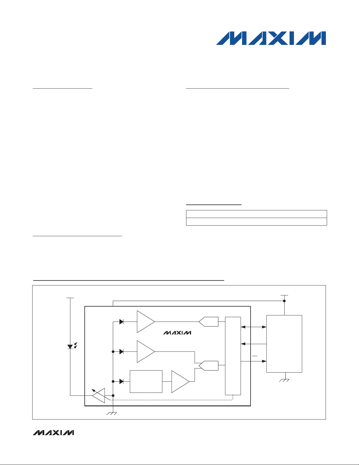
Simplified Block Diagram
Features
S Tiny, 2mm x 2mm x 0.6mm UTDFN-Opto Package
S VDD = 1.7V to 3.6V
S Low-Power Operation
5µA in Ambient Mode
7µA in Ambient Plus Proximity Mode
70µA in Ambient Plus Proximity Mode,
Including 100mA LED Current
S Excellent Light Source Matching
Programmable Green and IR Channel Gains
S Integrated Single-Pulse IR LED Driver
10mA to 110mA Programmable Range
Internal Ambient Cancellation
S -40NC to +105NC Temperature Range
Ordering Information
PART TEMP RANGE PIN-PACKAGE
MAX44000GDT+
+Denotes a lead(Pb)-free/RoHS-compliant package.
*EP = Exposed pad.
Typical Application Circuit appears at end of data sheet.
-40NC to +105NC
6 OTDFN-EP*
MAX44000
V
DD
MICROCONTROLLER
GND
IR LED
V
LED
V
DD
VIS + IR
(ALS)
IR (ALS)
IR (PRX)
DRV
GND
_______________________________________________________________ Maxim Integrated Products 1
ALS
PGA
ALS
PGA
AMBIENT
CANCELLATION
MAX44000
PRX
PGA
14-BIT
14-/8-BIT
I2C
SDA
SCL
INT
For pricing, delivery, and ordering information, please contact Maxim Direct at 1-888-629-4642,
or visit Maxim’s website at www.maxim-ic.com.
Page 2

Ambient and Infrared Proximity Sensor
ABSOLUTE MAXIMUM RATINGS
All Pins to GND ....................................................-0.3V to +4.0V
Output Short-Circuit Current Duration .......................Continuous
Continuous Input Current into Any Terminal ................... Q20mA
Stresses beyond those listed under “Absolute Maximum Ratings” may cause permanent damage to the device. These are stress ratings only, and functional
operation of the device at these or any other conditions beyond those indicated in the operational sections of the specifications is not implied. Exposure to absolute
maximum rating conditions for extended periods may affect device reliability.
Continuous Power Dissipation (TA = +70NC)
6-Pin OTDFN (derate 11.9mW/NC above +70NC) ............ 953mW
Operating Temperature Range ........................ -40NC to +105NC
Soldering Temperature (reflow) ......................................+260NC
MAX44000
ELECTRICAL CHARACTERISTICS
VDD = 1.8V, T
(
AMBIENT LIGHT RECEIVER CHARACTERISTICS
Maximum Ambient Light
Sensitivity
Ambient Light Saturation Level 65,535 Lux
Gain Error
Light Source Matching Fluorescent/incandescent light 10 %
Infrared Transmittance
Ultraviolet Transmittance
Dark Current Level
ADC Conversion Time
ADC Conversion Time Accuracy
INFRARED PROXIMITY RECEIVER CHARACTERISTICS
Maximum Proximity Detection
Sensitivity
Sunlight Rejection Offset No reflector 0 to 100k lux 0 Counts
Sunlight Rejection Gain Error With reflector 0 to 100k lux 0.1
– T
MIN
PARAMETER SYMBOL CONDITIONS MIN TYP MAX UNITS
= -40°C to +105°C, TA = +25°C, unless otherwise noted.) (Note 2)
MAX
Fluorescent light (Note 3) 0.03 Lux/LSB
Green LED 538nm response, TA = +25NC
(Note 3)
850nm vs. 538nm, TA = +25NC
363nm vs. 538nm, TA = +25NC
100ms conversion time, 0 lux, TA = +25NC
14-bit resolution, has 50Hz/60Hz rejection 100
12-bit resolution 25
10-bit resolution 6.25
8-bit resolution 1.56
TA = -40NC to +105NC
TA = +25NC
850nm IR LED, 60µW/cm
2
15 %
0.5 %
2 %
0 Count
6
0.7
1.5
mW/cm2/
ms
%
LSB
Counts/
klux
2 ______________________________________________________________________________________
Page 3

Ambient and Infrared Proximity Sensor
ELECTRICAL CHARACTERISTICS (continued)
VDD = 1.8V, T
(
IR LED TRANSMITTER
Minimum IR LED Drive Current
Sink
Maximum IR LED Drive Current
Sink
Current Control Step 10 mA
Current Control Accuracy
DRV Leakage Current I
Voltage Compliance of DRV Pin
Internal Transmit Pulse Width 100
POWER SUPPLY
Power-Supply Voltage V
Quiescent Current
(Ambient Mode)
Software Shutdown Current I
Quiescent Current Proximity During IR LED pulsed operation 375 600
Quiescent Current (ALS +
Proximity, Time Average)
Power-Up Time t
DIGITAL CHARACTERISTICS (SDA, SCL, INT)
Output Low Voltage (SDA, INT)
INT Leakage Current
SDA, SCL Input Current 0.01 1000 nA
I2C Input Low Voltage V
I2C Input High Voltage V
Input Capacitance 3 pF
– T
MIN
PARAMETER SYMBOL CONDITIONS MIN TYP MAX UNITS
= -40°C to +105°C, TA = +25°C, unless otherwise noted.) (Note 2)
MAX
I
= 110mA, V
OUT
= 50mA, V
OUT
I
= 10mA, V
OUT
= 0mA, V
OUT
I
= 110mA, DI
DRV
I
= 100mA, DI
DRV
DD
Is 5 10
SHDN
ON
V
IL_I2C
IH_I2C
TA = +25NC
TA = -40NC to +105NC
With proximity and ALS sensing on 6.8
I
OL
= 6mA 0.06 0.4 V
SINK
SDA, SCL 0.4 V
SDA, SCL 1.6 V
= 1.5V 12
DRV
= 1.5V 10
DRV
= 1.5V 12
DRV
= 3.6V 0.1
DRV
= 10%; V
OUT
OUT
= 2%, V
DRV
DRV
= 3.6V
= 3.6V
10 mA
110 mA
0.5
0.6
1.7 3.6 V
0.1 0.3
0.6
100 ms
0.01 1000 nA
MAX44000
%I
FA
V
Fs
FA
FA
FA
FA
_______________________________________________________________________________________ 3
Page 4
Ambient and Infrared Proximity Sensor
ELECTRICAL CHARACTERISTICS (continued)
VDD = 1.8V, T
(
PARAMETER SYMBOL CONDITIONS MIN TYP MAX UNITS
I2C TIMING CHARACTERISTICS
Serial-Clock Frequency f
Bus Free Time Between STOP
and START
Hold Time (Repeated) START
MAX44000
Condition
Low Period of the SCL Clock t
High Period of the SCL Clock t
Setup Time for a REPEATED
START
Data Hold Time t
Data Setup Time t
SDA Transmitting Fall Time t
Setup Time for STOP Condition t
Pulse Width of Suppressed Spike t
Note 2: All devices are 100% production tested at TA = +25NC. Temperature limits are guaranteed by design.
Note 3: Guaranteed by design. Green 538nm LED chosen for production so that the IC responds to 100 lux flourescent light with
100 lux.
MIN
– T
= -40°C to +105°C, TA = +25°C, unless otherwise noted.) (Note 2)
MAX
SCL
t
BUF
t
HD,STA
LOW
HIGH
t
SU.STA
HD,DAT
SU,DAT
I
P 6mA, tR and tF between 0.3 x VDD
F
SU,STO
SP
SINK
and 0.7 x V
DD
400 kHz
1.3
0.6
1.3
0.6
0.6
0 0.9
100 ns
100 ns
0.6
0 50 ns
Fs
Fs
Fs
Fs
Fs
Fs
Fs
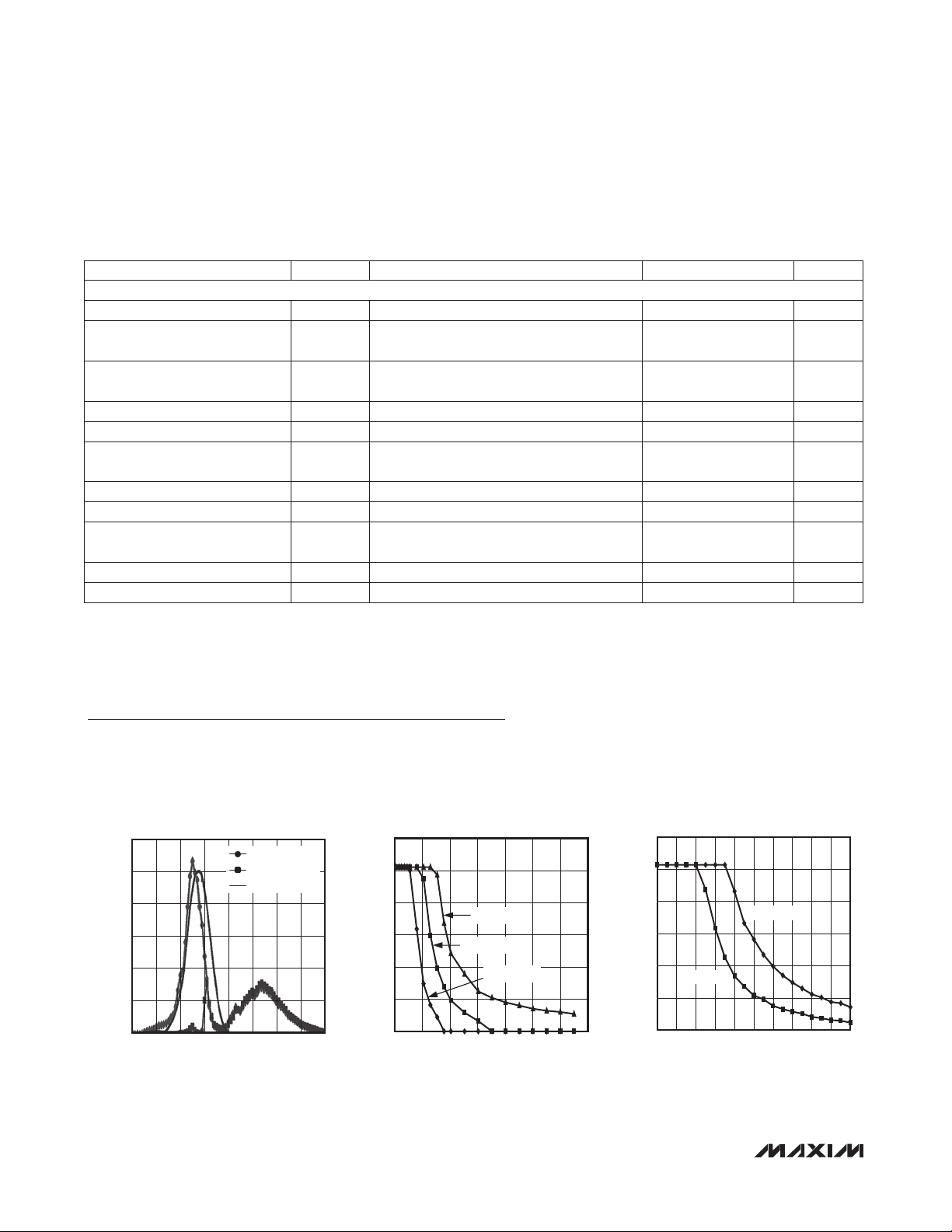
Typical Operating Characteristics
(VDD = 1.8V, T
Temperature limits are guaranteed by design.)
120
100
80
60
40
NORMALIZED OUTPUT
20
0
270 1070
4 ______________________________________________________________________________________
MIN
– T
= -40°C to +85°C, unless otherwise noted. All devices are 100% production tested at T
MAX
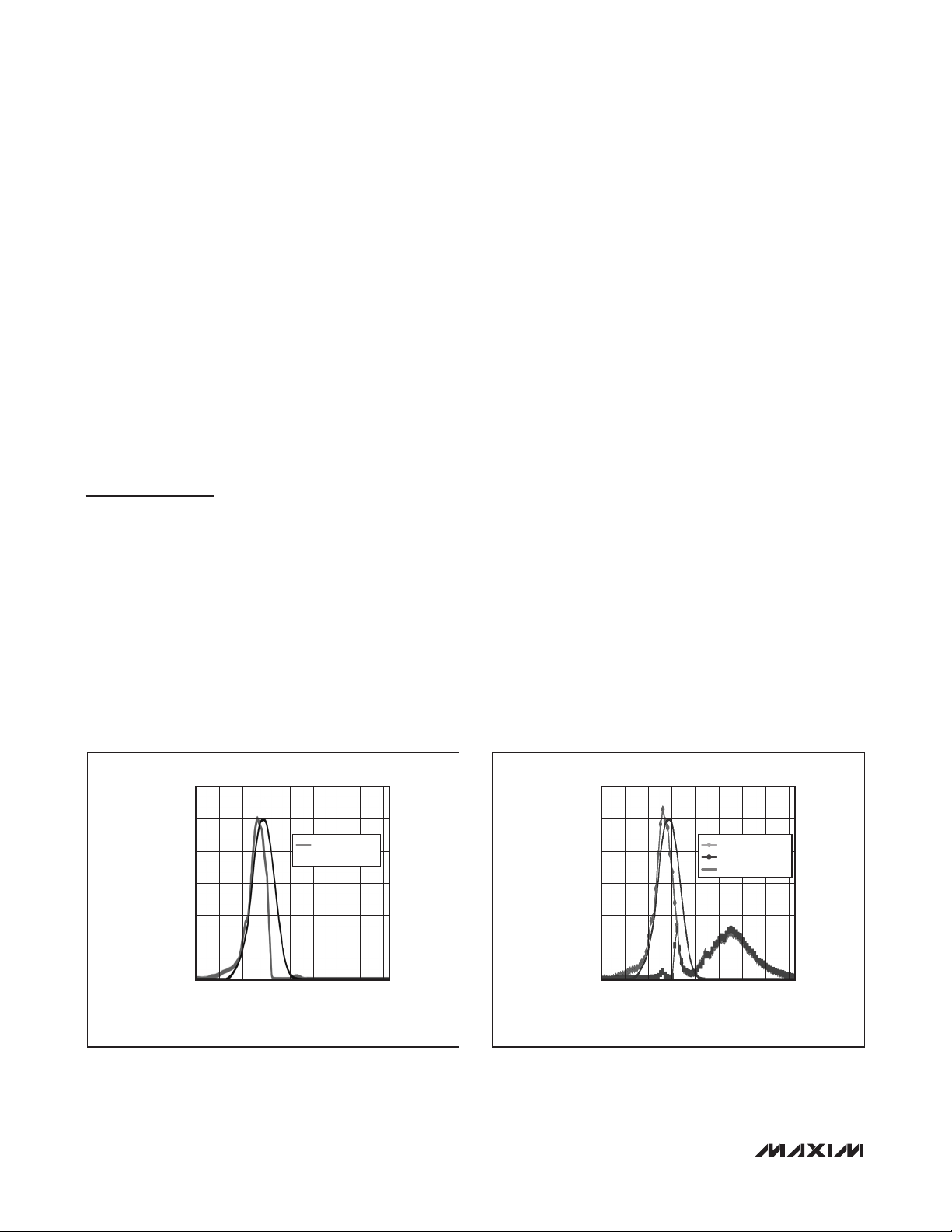
SPECTRUM RESPONSE
GREEN CHANNEL
RED CHANNEL
CIE CURVE
WAVE LENGTH (nm)
= +25°C.
A
ADC COUNT vs. DISTANCE
300
vs. LED DRIVE CURRENT
250
MAX44000 toc01
200
150
ADC COUNT
100
50
0
970870770670570470370
0 140
I
= 110mA
OUT
I
= 50mA
OUT
I
= 20mA
OUT
DISTANCE (mm)
MAX44000 toc02a
12010080604020
ADC COUNT vs. DISTANCE vs. OBJECT
300
250
200
150
ADC COUNT
100
50
0
GREY CARD
WHITE CARD
DISTANCE (mm)
9080706050403020100 100
MAX44000 toc02b
Page 5
Ambient and Infrared Proximity Sensor
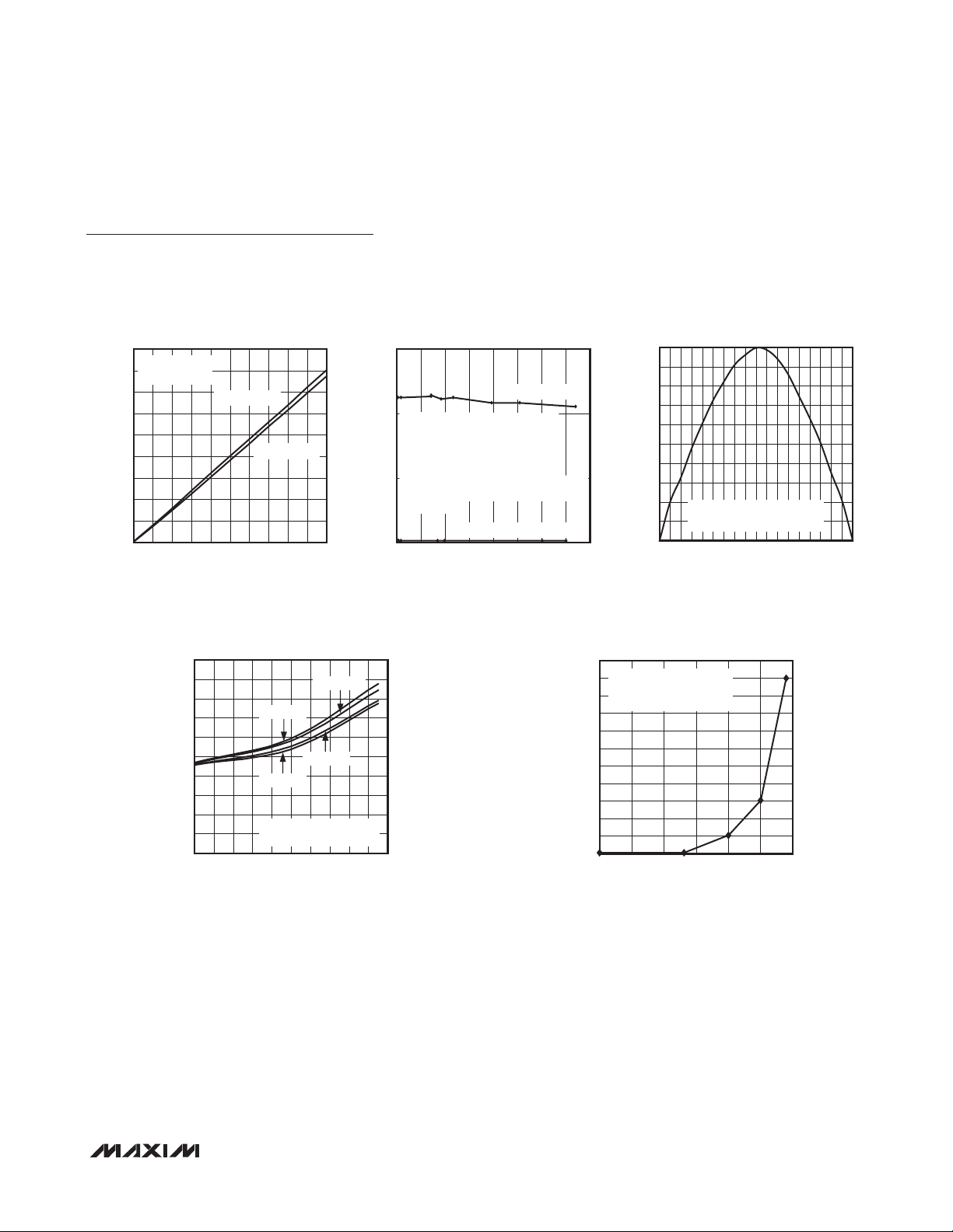
Typical Operating Characteristics (continued)
(VDD = 1.8V, T
Temperature limits are guaranteed by design.)
MIN
– T
= -40°C to +85°C, unless otherwise noted. All devices are 100% production tested at T
MAX
= +25°C.
A
MAX44000
LIGHT SENSITIVITY vs. LUX LEVEL
1800
ALSTIM[1:0] = 00
1600
ALSPGA[1:0] = 10
1400
1200
1000
800
ADC COUNT
600
400
200
0
0 1000
REFERENCE METER READING (LUX)
FLUORESCENT
INCANDESCENT
SUPPLY CURRENT vs. SUPPLY VOLTAGE
vs. TEMPERATURE
10
9
8
7
6
5
4
3
SUPPLY CURRENT (µA)
2
1
0
1.7 3.7
TA = +105°C
TA = -40°C
SUPPLY VOLTAGE (V)
MAX44000 toc03
ADC COUNT
900800600 700200 300 400 500100
TA = +85°C
TA = +25°C
STANDARD AMBIENT MODE
DARKROOM CONDITION
3.53.32.9 3.12.1 2.3 2.5 2.71.9
150
SUNLIGHT REJECTION
NO REFLECTOR
100
PRXTIM, PRXPGA : 0x02 = 1111 xxxx
LED CURRENT: 0x03 = xxxx 1110 for 100mA
WITH NO REFLECTOR, PROX COUNT STAYED
AT 0 AT ALL lux LEVEL
WITH A BLACK GLASS AS REFLECTOR AND
lux LEVEL CHANGED FROM 50 TO 75000 lux
50
PROX COUNTS DROPPED BY 7% AT MID-ADC RANGE
PROX COUNT DROPPED BY 35% AT QUARTER
ADC RANGE
0
0 80k
MAX44000 toc05
BLACK GLASS REFLECTOR
SUNLIGHT (LUX)
100
90
80
MAX44000 toc03b
70
60
50
40
30
20
RELATIVE SENSITIVITY (% FROM 0°)
10
70k60k50k40k30k20k10k
0
ROTATED WITH AXIS BETWEEN
PIN 1/2/3 AND 4/5/6
-50
-30
-70
-90 50 70 90
-40
LUMINOSITY ANGLE (°)
OUTPUT ERROR vs. TEMPERATURE
11
STANDARD AMBIENT MODE
10
DARKROOM CONDITION
9
V
= 1.7 V TO 3.6V
DD
8
7
6
5
4
COUNTS (UNITS)
3
2
1
0
-40 110
TEMPERATURE (°C)
RADIATION PATTERN
-20
-10
MAX44000 toc04
3010
40 60 80
20-60
0-80
MAX44000 toc06
85603510-15
_______________________________________________________________________________________ 5
Page 6
Ambient and Infrared Proximity Sensor
51
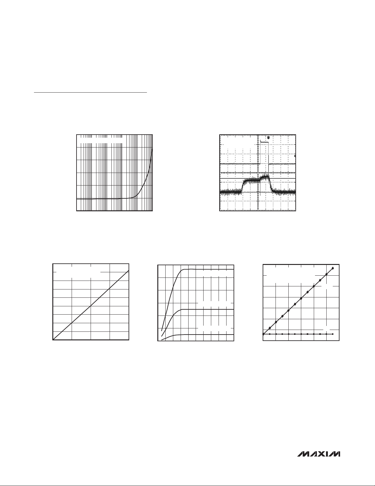
Typical Operating Characteristics (continued)
(VDD = 1.8V, T
Temperature limits are guaranteed by design.)
MIN
– T
= -40°C to +85°C, unless otherwise noted. All devices are 100% production tested at T
MAX
= +25°C.
A
30
STANDARD AMBIENT MODE
MAX44000
25
20
15
10
SUPPLY CURRENT (µA)
5
0
1 100k
OUTPUT LOW VOLTAGE
vs. SINK CURRENT
180
THE DATA WAS TAKEN ON
160
THE INTERRUPT PIN
140
120
100
80
60
OUTPUT LOW VOLTAGE (V)
40
20
0
SINK CURRENT (mA)
SUPPLY CURRENT vs. LUX
10k100010010
LUX
MAX44000 toc09
2010
5
MAX44000 toc07
IR LED CURRENT vs. OUTPUT DRIVE
120
VOLTAGE, I
100
80
(mA)
60
DRV
I
40
20
0 1.0
vs. V
DRV
110mA I
50mA I
10mA I
V
(V)
DRV
DRV
DRV
DRV
DRV
SETTING
SETTING
SETTING
SUPPLY CURRENT vs. TIME
AMBIENT +
PROXIMITY MODE
100µs/div
70
60
MAX44000 toc10
50
40
30
TOTAL CURRENT (uA)
20
10
0.90.80.70.60.50.40.30.20.1
0
MAX44000 toc08
I
DRV
50mA/div
I
DD
200µA/div
TOTAL CURRENT CONSUMPTION
INCLUDING IR LED CURRENT
vs. IR LED CURRENT LEVEL
I
= IDD + I
TOTAL
AMBIENT + PROXIMITY MODE
100ms INTEGRATION TIME
IR_LED
I
IR LED LEVEL (mA)
TOTAL
I
DD
10080604020
MAX44000 toc11
120
6 ______________________________________________________________________________________
Page 7
Ambient and Infrared Proximity Sensor
Pin Configuration
TOP VIEW
MAX44000
+
1
V
DD
2
GND SCL
3
DRV
*EP = EXPOSED PAD, CONNECT TO GND.
MAX44000
EP*
6
SDA
5
4
INT
Pin Description
PIN NAME FUNCTION
1 V
2 GND Ground
3 DRV IR LED Current Driver
4
5 SCL I2C Clock
6 SDA I2C Data
EP — Exposed Pad. EP is internally connected to GND. EP must be connected to GND.
DD
INT
Power Supply
Interrupt. Active-low output.
Detailed Description
The MAX44000 combines a wide-dynamic range ambient light sensor with an integrated infrared proximity
sensor. The die is placed inside an optically transparent
(UTDFN-Opto) package. A photodiode array inside the
IC converts the light to a current, which is then processed by low-power circuitry into a digital value. The
data is then stored in an output register that is read by
an I2C interface.
The IC contains three types of photodiodes: a green photodiode and two types of infrared photodiodes. Ambient
light sensing (ALS) is accomplished by subtracting the
infrared ALS photodiode signal from the green ALS
photodiode signals after applying respective gains. The
_______________________________________________________________________________________ 7
infrared proximity photodiodes are optimized for better
sensitivity for near infrared signals, specifically 850nm,
and can be used for proximity sensor measurements.
In the ALS mode, the ALS photodiodes are connected to
two ADCs. The user can choose to view either just the
green ALS signal, or just the infrared ALS signal, or the
difference of the green and infrared ALS photodiodes.
In the proximity detect mode, the infrared proximity photodiodes are connected to the proximity receiver circuit
and then to an 8-bit ADC.
Three key features of the IC’s analog design are its lowpower design, single-pulse proximity receive operation,
and interrupt pin operation.
Page 8
Ambient and Infrared Proximity Sensor
The IC operates from a VDD of 1.7V to 3.6V and consumes just 5FA current in ALS mode and 7FA time-averaged in proximity mode. The on-chip IR proximity detector DC ambient rejection circuitry is synchronized with
pulsing of an integrated IR LED transmitter to improve
noise immunity from external fluctuating IR sources.
This scheme also reduces IR LED power consumption
compared to alternate methods and eliminates red-glow
problems with the use of 850nm IR LEDs; power con-
MAX44000
sumption is reduced to 11FA (time averaged), including the current consumption of an external IR LED. An
on-chip programmable interrupt function eliminates the
need to continually poll the device for data, resulting in a
significant power saving.
Ambient Light Sensing
The ambient light sensors are designed to detect brightness in the same way as human eyes do. To achieve this,
the light sensor needs to have a spectral sensitivity that
is identical to the photopic curve of the human eye (see
Figure 1). Small deviations from the photopic curve can
affect perceived brightness by ambient light sensors to
be wildly different. However, there are practical difficulties in trying to reproduce the ideal photopic curve in a
small cost-efficient package. The IC instead uses two
different types of photodiodes (a green and an infrared)
that have different spectral sensitivities—each of which
is amplified and subtracted on-chip with suitable gain
coefficients so that the most extreme light sources (fluorescent and incandescent) are well matched to a commercial illuminance lux meter.
The photopic curve represents a typical human eye’s
sensitivity to wavelength. As can be seen in Figure 1
and Figure 2, its peak sensitivity is at 555nm (green).
The human eye is insensitive to infrared (> 700nm) and
ultraviolet (< 400nm) radiation.
Variation between light sources can extend beyond the
visible spectral range. For example, fluorescent and
incandescent light sources with similar visible brightness
(lux) can have substantially different IR radiation content
(since the human eye is blind to it). Since this infrared
radiation can be picked up by silicon photodiodes, differences in light spectra can affect brightness measurement of light sensors. For example, light sources with
high IR content, such as an incandescent bulb or sunlight, would suggest a much brighter environment than
our eyes would perceive them to be. Other light sources
such as fluorescent and LED-based systems have very
little infrared content. The IC incorporates on-chip compensation techniques to minimize these effects and still
output an accurate lux response in a variety of lighting
conditions.
On-chip user-programmable green channel and IR channel gain trim registers allow the light sensor response to
be tailored to the application, such as when the light sensor is placed under dark or colored glass.
120
100
80
60
40
NORMALIZED RESPONSE
20
0
270 1070
WAVELENGTH (nm)
Figure 1. Spectral Response Compared to Ideal Photopic
Curve
8 ______________________________________________________________________________________
STANDARD ALS
(GREEN-RED)
970870770670570470370
Figure 2. Green Channel and IR Channel Response at
Identical Gains on a Typical MAX44000
120
100
80
60
40
NORMALIZED OUTPUT
20
0
270 1070
WAVELENGTH (nm)
GREEN CHANNEL
RED CHANNEL
CIE CURVE
970870770670570470370
Page 9

Ambient and Infrared Proximity Sensor
Proximity Light Sensing
The proximity sensing uses an external, pulsed infrared
LED source to emit controlled amounts of infrared radiation. When an external object reflects back some of this
infrared radiation back to the IC, it is detected by the
integrated light detector. The amount of reflected light
detected is then used to determine the object’s proximity
to the sensor.
It is important to take account for the fact that different
objects at the same distance from the sensor can reflect
different amounts of infrared radiation depending on
their texture and color.
The IC includes on-chip ambient cancellation circuitry
in the receive path of the infrared proximity sensor. This
scheme allows the part to operate in the presence of
large amounts of DC IR radiation. Due to the use of a
single-pulse technique in pulsing the external infrared
LED, the chip is also immune to fixed-frequency external
infrared radiation such as from remote controls, electronic ballasts, etc., leading to more reliable infrared
proximity sensor operation.
LED Driver
The IC features a LED driver that delivers a pulsed current at the output. The pulse amplitude is programmable
through the I2C interface from 0 to 110mA in steps of
10mA. A low-voltage compliance of DRV pin allows IR
LEDs to be powered from lower voltage rails, possibly
even a 1.8V rail. High-current drive accuracy improves
performance by eliminating part-to-part variation.
Register Description
REGISTER B7 B6 B5 B4 B3 B2 B1 B0
STATUS
Interrupt Status PWRON PRXINTS ALSINTS 0x00 0x04 R
CONFIGURATION
Main Configuration TRIM MODE[2:0] PRXINTE ALSINTE 0x01 0x24 R/W
Receive Configuration
Transmit Configuration DRV[3:0] 0x03 0x00 R/W
ADC DATA
ADC High Byte (ALS
ADC Low Byte (ALS
ADC Byte (PROX) PRXDATA[7:0] 0x16 0x00 R
THRESHOLD SET
ALS Upper Threshold
(High Byte
ALS Upper Threshold
(Low Byte)
ALS Lower Threshold
(High Byte)
ALS Lower Threshold
(Low Byte)
)
)
1 1 1 1 ALSTIM[1:0] ALSPGA[1:0] 0x02 0x00 R/W
)
OFL ALSDATA[13:8] 0x04 0x00 R
ALSDATA[7:0] 0x05 0x00 R
UPTHR[13:8] 0x06 0x00 R/W
UPTHR[7:0] 0x07 0x00 R/W
LOTHR[13:8] 0x08 0x00 R/W
LOTHR[7:0] 0x09 0x00 R/W
REGISTER
ADDRESS
POWER-ON
RESET
STATE
R/W
MAX44000
_______________________________________________________________________________________ 9
Page 10

Ambient and Infrared Proximity Sensor
Register Description (continued)
REGISTER B7 B6 B5 B4 B3 B2 B1 B0
Threshold Persist Timer PRXPST[1:0] ALSPST[1:0] 0x0A 0x00 R/W
PROX Threshold
Indicator
MAX44000
PROX Threshold PRXTHR[7:0] 0x0C 0x00 R/W
Digital Gain Trim of
Green Channel
Digital Gain Trim of
Infrared Channel
ABOVE 0x0B 0x00 R/W
TRIM_
TRIM_GAIN_GREEN[6:0]
TRIM_GAIN_IR[8:1] 0x10 0x80 R/W
GREEN_
IR[0]
REGISTER
ADDRESS
0x0F 0x80 R/W
POWER-ON
RESET
STATE
The individual register bits are explained below. Default power-up bit states are highlighted in bold.
Interrupt Status Register (0x00)
REGISTER B7 B6 B5 B4 B3 B2 B1 B0
Interrupt Status PWRON PRXINTS ALSINTS 0x00 0x04 R
REGISTER
ADDRESS
POWER-ON
RESET
STATE
The PWRON bit in the Interrupt Status register 0x00, if set, indicates that a power-on-reset (POR) condition has
occurred, and any user-programmed thresholds cannot be valid anymore. The ALSINTS bit in the Interrupt Status register 0x00 indicates that an ambient light interrupt condition has occurred. The PRXINTS bit in the Interrupt Status register 0x00 indicates that a proximity receive interrupt condition has occurred. If any of these bits is set to 1, the INT pin
is pulled low and asserted. Note: On Rev-1 of the device, the PWRON bit does not pull the INT pin low, even if set to 1.
Reading the Interrupt Status register clears the PWRON, ALSINTS, and PRXINTS bits, if set, and deasserts the INT
pin. INT is pulled high by the off-chip pullup resistor. The ALSINTS and PRXINTS bits are disabled and set to 0 if the
respective interrupt enable bits in Main Configuration register 0x01 are set to 0.
R/W
R/W
Ambient Interrupt Status (ALSINTS)
BIT 0 OPERATION
0 No interrupt trigger event has occurred.
The ambient light intensity has traversed outside the designated window limits defined by
1
10 _____________________________________________________________________________________
Threshold registers for greater than persist timer count ALSPST[1:0], or an overflow condition in the ambient light
readings has occurred. This bit also causes the INT pin to be pulled low. Once set, the only way to clear this bit is
to read this register or to set the ALSINTE bit in register 0x01 to 0.
Page 11

Ambient and Infrared Proximity Sensor
Proximity Interrupt Status (PRXINTS)
BIT 1 OPERATION
0 No interrupt trigger event has occurred.
The IR proximity receive intensity has exceeded the threshold limit for greater than persist
1
timer count PRXPST[1:0]. This bit also causes the INT pin to be pulled low. Once set, the only way to clear this bit is
to read this register or to set PRXINTE bit to 0.
Power-On Reset Status (PWRON)
BIT 2 OPERATION
0 No interrupt trigger event has occurred.
The part went through a power-up event, either because the part was turned on or because there was a power-
1
supply voltage glitch. All interrupt threshold settings in the registers have been reset to a default state and should
be examined. A 1 on this bit also causes the INT pin to be pulled low. Note: INT is not pulled low on Rev-1 of the
IC. Once this bit is set, the only way to clear this bit is to read this register.
Main Configuration Register (0x01)
REGISTER B7 B6 B5 B4 B3 B2 B1 B0
Main Configuration TRIM MODE[2:0] PRXINTE ALSINTE 0x01 0x24 R/W
REGISTER
ADDRESS
POWER-ON
RESET
STATE
R/W
This register is used to set the operating mode of the IC (ALS and/or proximity) and enable interrupt operation of the
device.
MAX44000
BIT 5 OPERATION
0
1
Use bytes written to TRIM_GAIN_GREEN[7:0] and TRIM_GAIN_IR[7:0] registers to set the fine-trim gain of the
green and IR gain channels.
Use factory-programmed gains for green and IR channels. Ignore bytes written to TRIM_GAIN_GREEN[7:0] and
TRIM_GAIN_IR[7:0] registers.
The 3-bit MODE[2:0] defines eight operating modes for the IC, as shown below.
MODE[2:0]
000 Shutdown Analog circuits are shut down, but the digital register retains values.
001 ALS G-IR
010 ALS G ALS green channel only. Proximity channel operation and updates are disabled.
011 ALS IR Infrared channel only. Proximity channel operation and updates are disabled.
100 ALS/PROX ALS and PROX are interleaved continuously.
101 PROX Only PROX only continuously. ALS channel operation and updates are disabled.
110 Reserved Do not use.
111 Reserved Do not use.
OPERATING
MODE
Standard ALS mode stores the difference between green and infrared channel readings.
Proximity channel operation and updates are disabled.
______________________________________________________________________________________ 11
OPERATION
TRIM
MODE[2:0]
Page 12

Ambient and Infrared Proximity Sensor
Proximity Interrupt Enable (PRXINTE)
BIT 1 OPERATION
0 The PRXINTS bit remains unasserted, and proximity channel readings are not compared with interrupt thresholds.
Detection of a proximity interrupt event triggers a hardware interrupt (INT pin is pulled low) and sets the PRXINTS
1
bit (register 0x00, B1). Proximity channel readings are compared with proximity interrupt threshold settings and
proximity persist timer.
MAX44000
BIT 0 OPERATION
0 The ALSINTS bit remains unasserted, and ALS channel readings are not compared with interrupt thresholds.
Detection of an ambient light interrupt event triggers a hardware interrupt (INT pin is pulled low) and sets the
1
ALSINTS bit (register 0x00, B0). ALS channel readings are compared with ALS interrupt threshold settings and
ALS persist timer.
Ambient Interrupt Enable (ALSINTE)
Receive Configuration Register (0x02)
REGISTER B7 B6 B5 B4 B3 B2 B1 B0
Receive Configuration 1 1 1 1 ALSTIM[1:0] ALSPGA[1:0] 0x02 0x00 R/W
REGISTER
ADDRESS
POWER-ON
RESET
STATE
This register sets the ADC integration time and front-end photodiode circuitry sensitivity (gain) for the ALS channel.
The ADC integration time also controls the bit resolution of measurements. ADC conversions are made of MSB first
(the IC needs longer conversion times for higher resolution measurements). Use of lower PGA gains helps expand the
full-scale range of the ADC at the expense of per-LSB sensitivity.
R/W
12 _____________________________________________________________________________________
Page 13

Ambient and Infrared Proximity Sensor
Ambient ADC Conversion Time (ALSTIM)
The 2-bit ALSTIM[1:0] sets the integration time for ALS ADC conversion, as shown in Table 1.
Table 1. Ambient ADC Conversion Time
ALSTIM[1:0] INTEGRATION TIME (ms)
00 100 16,384 14 1x
01 25 4096 12 4x
10 6.25 1024 10 16x
11 1.5625 256 8 64x
The 2-bit ALSPGA[1:0] sets the gain of the ambient light sensing measurement according to Table 2.
FULL-SCALE ADC
COUNTS
BIT RESOLUTION RELATIVE LSB SIZE
Ambient Light Measurement Gain (ALSPGA)
Table 2. Ambient Light Measurement Gain
ALSPGA[1:0] LUX/LSB RELATIVE LSB SIZE
00 0.03125 1x
01 0.125 4x
10 0.5 16x
11 4 128x
MAX44000
Transmit Configuration Register (0x03)
This register controls the driver current setting and is used when the Proximity channel is enabled.
REGISTER B7 B6 B5 B4 B3 B2 B1 B0
Transmit Configuration DRV[3:0] 0x03 0x00 R/W
REGISTER
ADDRESS
POWER-ON
RESET
STATE
R/W
LED Drive Current Setting (DRV)
The 4 bits of DRV set the LED drive current according to Table 3.
Table 3. LED Drive Current Settings
DRV[3:0] LED CURRENT (mA) DRV[3:0] LED CURRENT (mA)
0000 LED driver disabled 1000 40
0001 10 1001 50
0010 20 1010 60
0011 30 1011 70
0100 40 1100 80
0101 50 1101 90
0110 60 1110 100
0111 70 1111 110
______________________________________________________________________________________ 13
Page 14

Ambient and Infrared Proximity Sensor
ALS Data Register (0x04, 0x05)
REGISTER B7 B6 B5 B4 B3 B2 B1 B0
ADC High Byte (ALS) OFL ALSDATA[13:8] 0x04 0x00 R
ADC Low Byte (ALS) ALSDATA[7:0] 0x05 0x00 R
The 2 bytes here (ALSDATA[13:0]) hold the results of the ALS signal conversion. The resolution and bit length of the
MAX44000
result is controlled by the value of ALSTIM[1:0] and ALSPGA[1:0] bits. The result is always right justified in the two
registers, and the unused high bits are zero.
OFL indicates an overflow condition on the ALS channel. If this occurs, set the ALS range (ALSPGA[1:0]) to a higher
range. If the OFL bit is set to 1 (there is an overflow condition), and the ALSINTE bit is set to 1 (enabled), then the
ALSINTS bit is set to 1 and the INT pin is pulled low.
The data in this register could be the green channel, infrared channel, or ALS readings (green channel, infrared channel readings), depending on the mode selected by the user.
Internal update of these two registers is disabled during I2C read operations to ensure proper data handoff between
the ADC and the I2C registers. Update of the I2C registers is resumed once the master sends a STOP (P) command.
Therefore, when reading the 2 bytes of this register, the master should not send a STOP command between the 2-byte
reads. Instead, a Repeated START (Sr) command should be used. The exact read sequence using the Repeated
START command is shown in the I2C Serial Interface section.
REGISTER
ADDRESS
POWER-ON
RESET
STATE
PROX Data Registers (0x15, 0x16)
REGISTER B7 B6 B5 B4 B3 B2 B1 B0
ADC Byte (PROX) PRXDATA[7:0] 0x16 0x00 R
The byte here (PRXDATA[7:0]) hold the results of the proximity receive signal conversion. Internal update of the register
is disabled during I2C read operations to ensure proper data handoff between the ADC and the I2C registers. Update
of the I2C registers is resumed once the master sends a STOP command.
REGISTER
ADDRESS
POWER-ON
RESET
STATE
R/W
R/W
14 _____________________________________________________________________________________
Page 15

Ambient and Infrared Proximity Sensor
ALS Interrupt Threshold Registers (0x06–0x09)
POWER-ON
RESET
STATE
R/W
REGISTER B7 B6 B5 B4 B3 B2 B1 B0
ALS Upper Threshold
(High Byte)
ALS Upper Threshold
(Low Byte)
ALS Lower Threshold
(High Byte)
ALS Lower Threshold
(Low Byte)
UPTHR[7:0] 0x07 0x00 R/W
LOTHR[7:0] 0x09 0x00 R/W
UPTHR[13:8] 0x06 0x00 R/W
LOTHR[13:8] 0x08 0x00 R/W
REGISTER
ADDRESS
The ALS upper threshold and ALS lower threshold (UPTHR[13:0] and LOTHR[13:0]) set the window limits that are used
to trigger an ALS interrupt. It is important to set these values according to the selected bit resolution/integration time
chosen for the ALS measurement based on the ALSTIM[1:0] and ALSPGA[1:0] settings. The upper 2 bits are always
ignored. If the INTE bit is set, and the lux level is greater or lower than the respective thresholds for a period greater
than that defined by the ALSPST persist time, the INTS bit in the Status register is set and the INT pin is pulled low.
ALS/PROX Threshold Persist Timer Register (0x0A)
REGISTER B7 B6 B5 B4 B3 B2 B1 B0
Threshold Persist Timer PRXPST[1:0] ALSPST[1:0] 0x0A 0x00 R/W
REGISTER
ADDRESS
POWER-ON
RESET
STATE
R/W
MAX44000
The MAX44000 incorporates a persist function that allows the users to set the number of consecutive triggers before
interrupt. PRXPST[1:0] and ALSPST[1:0] set one of four persist values that control how readily the interrupt logic reacts
to a detected event. This feature is added to reduce false or nuisance interrupts.
PRXPST[1:0] OR ALSPST[1:0] NO. OF CONSECUTIVE TRIGGERS BEFORE INTERRUPT
00 1
01 2
10 4
11 16
When ALSPST[1:0] is set to 00, and the ALSINTE bit is set to 1, the first time an ALS interrupt event is detected, the
ALSINTE interrupt bit is set and the INT pin goes low. If ALSPST[1:0] is set to 01, then four consecutive interrupt events
must be detected on four consecutive measurement cycles. Similarly, if ALSPST[1:0] is set to 10, or 11, then 8 or 16
consecutive interrupts must be detected. If there is an intervening measurement cycle where no interrupt is detected,
then the count is reset to zero. The proximity interrupt function is managed in the same way with PRXPST[1:0].
______________________________________________________________________________________ 15
Page 16

Ambient and Infrared Proximity Sensor
Proximity Threshold Registers (0x0B, 0x0C)
REGISTER B7 B6 B5 B4 B3 B2 B1 B0
PROX Threshold Indicator ABOVE 0x0B 0x00 R/W
PROX Threshold PRXTHR[7:0] 0x0C 0x00 R/W
REGISTER
ADDRESS
POWER-ON
RESET
STATE
The value set by PRXTHR[7:0] in combination with the ABOVE bit controls the operation of the proximity interrupt function. If the ABOVE bit is set to 1, the proximity interrupt has been enabled (PRXINTE = 1), and the result of a proximity
MAX44000
measurement is greater than the value stored in PRXTHR[7:0], then a proximity interrupt event is recorded. The interrupt bit is set subject to count conditions set by PRXPST[1:0]. Similarly, if the ABOVE bit is set to 0, then an interrupt
event is recorded if the result of a proximity measurement is less than value stored in PRXTHR[7:0].
Digital Gain Trim Registers (0x0F, 0x10)
REGISTER B7 B6 B5 B4 B3 B2 B1 B0
Digital Gain Trim of
Green Channel
Digital Gain Trim of
Infrared Channel
Note: Values read from TRIM_GAIN_ registers are the complements of the written value. This is true for reading both the factoryprogrammed values and the customer-programmed values.
TRIM_GAIN_GREEN[6:0]
TRIM_GAIN_IR[8:1] 0x10 0x80 R/TW
TRIM_
GAIN_
REGISTER
ADDRESS
0x0F 0x80 R/TW
IR[0]
POWER-ON
RESET
STATE
R/W
R/W
TRIM_GAIN_GREEN[6:0] is used to modify the gain of the green channel.
TRIM_GAIN_IR[8:0] is used to modify the gain of the IR channel.
To tell the part to use the values written to this register, set the TRIM bit to 0 in the Main Configuration register after
writing new values to these registers.
16 _____________________________________________________________________________________
Page 17

Ambient and Infrared Proximity Sensor
Applications Information
Ambient Sensing Applications
Typical applications involve placing the IC behind a
glass with a small semitransparent window placed above
it. Use the photodiode sensitive area as shown in Figure
3 to properly position the window above the part.
The part comes equipped with internal gain trim registers for the green and IR ALS photodiodes. By suitably
choosing the gains for these channels, accurate ambient
light readings can be generated in all lighting conditions
irrespective of the type of glass the part is used under.
This is especially useful for black-glass applications,
where for cosmetic reasons, the part is placed behind
a black film to hide its presence, and this film has the
peculiar property of attenuating most ambient light, but
passing through infrared radiation.
In standard ALS mode, the green channel and infrared
channel readings are internally subtracted. Since one is
observing only the difference in two separate ADC measurements, wrong readings can be obtained if one of the
channels becomes saturated, while the other channel
continues to rise. Since both the green photodiode also
picks up a lot of the infrared signal, this saturation can
occur much before the maximum expected full-scale
range in certain lighting conditions. For example, under
incandescent light, there is a lot more infrared optical
power than in the visible spectral range. In these situations, the green channel can saturate much earlier than
511 lux in the most sensitive range. To assist the user in
detecting these conditions, an OFL bit is provided that
alerts the user of an overrange condition. This bit also
triggers an ALS interrupt if it has been enabled.
Proximity Sensing Applications
The IC integrates a novel proximity sensor interface
circuit with a robust built-in ambient IR cancellation
scheme. The internal DC IR rejection circuit eliminates
problems of ADC saturation in the presence of strong
ambient infrared radiation, such as bright sunlight.
Further, the proximity sensor uses a single-pulse scheme
for the IR transmitter that eliminates red-glow problems
seen in competing solutions to drive 850nm IR LEDs,
while also reducing average IR LED power consumption
to less than 0.1% of the IR LED peak current.
2mm
V
CC
1
1.226mm
GND
0.39mm
DRV
Figure 3. Photodiode Location
0.753mm
2
3
MAX44000
TOP VIEW
PHOTO-
DIODE
0.492mm
6 SDA
5SCL
4
INT
2mm
Interrupt Operation
Ambient interrupt is enabled by setting bit 0 of register
0x01 to 1 and proximity interrupt is enabled by setting
bit 1 of register 0x01 to 1 (see Table 1 and Table 2). The
interrupt pin, INT, is an open-drain output and pulls low
when an interrupt condition occurs (e.g., when ambient
lux readings exceed threshold limits for a period greater
than that set by the Time register). The interrupt status bit
is cleared automatically if register 0x00 is read or if the
interrupts are disabled.
A PWRON interrupt bit is set to alert the master of a chip
reset operation in case of a power-supply glitch that can
happen on smartphones that place the light sensor on a
flex with a small connector.
It is best to utilize the interrupt pin on the IC to alert the
master to come and read measurements from the IC. This
eliminates the need for the microcontroller (I2C master)
to continually poll the device for information. Due to the
use of pullup resistors on the I2C bus, minimizing I2C bus
activity can reduce power consumption substantially. In
addition, this frees up the microcontroller resources to
service other background processes to improve device
performance. The wide variety of smarts available on the
chip, such as the ability to set the threshold levels and to
count persist timer limits, allow the part to operate in an
autonomous mode most of the time.
MAX44000
______________________________________________________________________________________ 17
Page 18

Ambient and Infrared Proximity Sensor
Interrupt Pin Voltage Compliance
The interrupt pin can withstand external voltages up
to 4V when in high-impedance mode per the absolute
maximum ratings of the IC. However, when the voltage
on the INT pin is higher than the VDD of the part (such as
when external pullup voltage is greater than VDD of part),
there is a small leakage current of 25µA sink into INT. This
additional current drawn through the INT pin should also
be accounted for in power-sensitive applications.
MAX44000
The typical operating sequence for the master to communicate to the IC is shown below:
1) Read the Interrupt Status register (0x00) to confirm
only the PWRON bit is set. This also clears a hardware interrupt. Note: For Rev-1 devices, a PWRON
interrupt does not trigger a hardware interrupt.
2) Set the Threshold and Threshold Persist Timer
registers for ambient and proximity sensor measurements (Registers 0x06–0x0C). Note: For Rev-1
devices, leave the Threshold Persist Timer register
(Register 0x0A) set to 0.
3) Write F0 to the Receive Configuration register
(Register 0x02) to set the ALS sensor in the highest gain setting and ALS ADCs in 14-bit modes of
operation.
4) Set the IR LED current to a suitable level by writing
to the Transmit Configuration register (0x03).
5) Write 0x13 to Main Configuration register (register
0x01) to set the part in ALS + proximity mode, and
to enable ALS and proximity interrupts.
6) Set the new green channel gains and infrared
channel gains, if necessary, to customize ALS
operation for application conditions. Ensure the
TRIM bit is set to 0 when not using default factorytrim settings.
7) Wait for interrupt.
8) Read the Interrupt Status register (0x00) to confirm
the IC to be the source of interrupt, and to check
for the type of interrupt. If set, this should clear the
hardware interrupt on the part.
Typical Operating Sequence
9) If an ALS interrupt has occurred, read the ADC
High Byte (ALS) and ADC Low Byte (ALS) registers
(registers 0x04, 0x05) to confirm if data is valid (i.e.,
OFL = 0), and take appropriate action (e.g., sets
new backlight strength). Set new ALS thresholds, if
necessary.
10) If a PROX interrupt has occurred, read the PROX
ADC registers (register 0x15) and take appropriate
action (typically, turn off or turn on touch screen
and backlight). Set new proximity thresholds, if
necessary.
11) Return to step 7.
I2C Serial Interface
The IC features an I2C/SMBus-compatible, 2-wire serial
interface consisting of a serial-data line (SDA) and a
serial-clock line (SCL). SDA and SCL facilitate communication between the IC and the master at clock rates
up to 400kHz. Figure 4 shows the 2-wire interface timing diagram. The master generates SCL and initiates
data transfer on the bus. A master device writes data
to the IC by transmitting the proper slave address followed by the register address and then the data word.
Each transmit sequence is framed by a START (S) or
Repeated START condition and a STOP condition. Each
word transmitted to the IC is 8 bits long and is followed
by an acknowledge clock pulse. A master reading data
from the IC transmits the proper slave address followed
by a series of nine SCL pulses. The IC transmits data
on SDA in sync with the master-generated SCL pulses.
The master acknowledges receipt of each byte of data.
Each read sequence is framed by a START or Repeated
START condition, a not acknowledge, and a STOP condition. SDA operates as both an input and an open-drain
output. A pullup resistor, typically greater than 500I, is
required on the SDA bus. SCL operates as only an input.
A pullup resistor, typically greater than 500I, is required
on SCL if there are multiple masters on the bus, or if the
master in a single-master system has an open-drain SCL
output. Series resistors in line with SDA and SCL are
optional. Series resistors protect the digital inputs of the
IC from high-voltage spikes on the bus lines, and minimize crosstalk and undershoot of the bus signal.
Table 4. Slave Address
SLAVE ADDRESS FOR WRITING SLAVE ADDRESS FOR READING
1001 0100 1001 0101
18 _____________________________________________________________________________________
Page 19

Ambient and Infrared Proximity Sensor
rP
SDA
t
SU,DAT
t
LOW
SCL
t
t
HD,STA
START
CONDITION
Figure 4. 2-Wire Interface Timing Diagram
HIGH
t
R
MAX44000
t
STOP
BUF
START
CONDITION
t
SU,STA
t
HD,DAT
t
F
REPEATED
START CONDITION
t
HD,STA
t
SP
t
SU,STO
CONDITION
Bit Transfer
One data bit is transferred during each SCL cycle. The
data on SDA must remain stable during the high period
of the SCL pulse. Changes in SDA while SCL is high are
control signals. See the START and STOP Conditions section. SDA and SCL idle high when the I2C bus is not busy.
START and STOP Conditions
SDA and SCL idle high when the bus is not in use. A
master initiates communication by issuing a START condition. A START condition is a high-to-low transition on
SDA with SCL high. A STOP condition is a low-to-high
transition on SDA while SCL is high (Figure 5). A START
condition from the master signals the beginning of a
transmission to the IC. The master terminates transmission, and frees the bus by issuing a STOP condition. The
bus remains active if a Repeated START condition is
generated instead of a STOP condition.
Early STOP Conditions
The IC recognizes a STOP condition at any point during
data transmission except if the STOP condition occurs in
SS
SCL
the same high pulse as a START condition. For proper
operation, do not send a STOP condition during the
same SCL high pulse as the START condition.
Acknowledge
The acknowledge bit (ACK) is a clocked 9th bit that the
IC uses to handshake receipt of each byte of data when
in write mode (Figure 6). The IC pulls down SDA during the entire master-generated ninth clock pulse if the
previous byte is successfully received. Monitoring ACK
allows for detection of unsuccessful data transfers. An
unsuccessful data transfer occurs if a receiving device
is busy or if a system fault has occurred. In the event of
an unsuccessful data transfer, the bus master can retry
communication. The master pulls down SDA during the
ninth clock cycle to acknowledge receipt of data when
the IC is in read mode. An acknowledge is sent by the
master after each read byte to allow data transfer to
continue. A not acknowledge is sent when the master
reads the final byte of data from the IC, followed by a
STOP condition.
CLOCK PULSE FOR
ACKNOWLEDGMENT
CONDITION
SCL
START
1
289
SDA
SDA
Figure 5. START, STOP, and Repeated START Conditions Figure 6. Acknowledge
______________________________________________________________________________________ 19
NOT ACKNOWLEDGE
ACKNOWLEDGE
Page 20

Ambient and Infrared Proximity Sensor
Write Data Format
A write to the IC includes transmission of a START condition, the slave address with the R/W bit set to 0, 1 byte
of data to configure the internal register address pointer,
one or more bytes of data, and a STOP condition. Figure
7 illustrates the proper frame format for writing 1 byte of
data to the IC.
The slave address with the R/W bit set to 0 indicates
that the master intends to write data to the IC. The IC
MAX44000
acknowledges receipt of the address byte during the
master-generated ninth SCL pulse.
The second byte transmitted from the master configures
the IC’s internal register address pointer. The pointer
tells the IC where to write the next byte of data. An
acknowledge pulse is sent by the IC upon receipt of the
address pointer data.
The third byte sent to the IC contains the data that is
written to the chosen register. An acknowledge pulse
from the IC signals receipt of the data byte. Figure 8 illustrates how to write to multiple registers with one frame.
The master signals the end of transmission by issuing a
STOP condition.
Read Data Format
Send the slave address with the R/W bit set to 1 to initiate a read operation. The IC acknowledges receipt of
its slave address by pulling SDA low during the ninth
SCL clock pulse. A START command followed by a read
command resets the address pointer to register 0x00.
The first byte transmitted from the IC is the contents of
register 0x00. Transmitted data is valid on the rising edge
of the master-generated serial clock (SCL). The address
pointer autoincrements after each read data byte. This
autoincrement feature allows all registers to be read
sequentially within one continuous frame. A STOP condition can be issued after any number of read data bytes.
If a STOP condition is issued followed by another read
operation, the first data byte to be read is from register
0x00 and subsequent reads autoincrement the address
pointer until the next STOP condition. The address
pointer can be preset to a specific register before a read
command is issued. The master presets the address
pointer by first sending the IC’s slave address with the
R/W bit set to 0 followed by the register address. A
Repeated START condition is then sent, followed by the
slave address with the R/W bit set to 1. The IC transmits the contents of the specified register. The address
pointer autoincrements after transmitting the first byte.
Attempting to read from register addresses higher than
0xFF results in repeated reads of 0xFF. Note that 0xF6
to 0xFF are reserved registers. The master acknowledges receipt of each read byte during the acknowledge
clock pulse. The master must acknowledge all correctly
received bytes except the last byte. The final byte must
be followed by a not acknowledge from the master and
then a STOP condition. Figure 8 illustrates the frame
format for reading 1 byte from the IC. Figure 9 illustrates
the frame format for reading two registers consecutively
without a STOP condition in between reads.
ACKNOWLEDGE FROM MAX44000
ACKNOWLEDGE FROM MAX44000
S AA
Figure 7. Writing 1 Byte of Data to the IC
20 _____________________________________________________________________________________
0SLAVE ADDRESS REGISTER ADDRESS DATA BYTE
R/W
ACKNOWLEDGE FROM MAX44000
1 BYTE
B1 B0B3 B2B5 B4B7 B6
A
P
Page 21

Ambient and Infrared Proximity Sensor
MAX44000
ACKNOWLEDGE FROM MAX44000
SA
R/W
ACKNOWLEDGE FROM MAX44000
0
Figure 8. Reading 1 Indexed Byte of Data from the IC
ACKNOWLEDGE FROM MAX44000
SA
R/W
ACKNOWLEDGE FROM MAX44000
ACKNOWLEDGE FROM MAX44000
0
ACKNOWLEDGE FROM MAX44000
0
AS
R/W
ACKNOWLEDGE FROM MAX44000
Sr 1SLAVE ADDRESS REGISTER ADDRESS SLAVE ADDRESS DATA BYTE
ACKNOWLEDGE FROM MAX44000
Sr 1SLAVE ADDRESS REGISTER ADDRESS 1 SLAVE ADDRESS DATA BYTE 1
ACKNOWLEDGE FROM MAX44000
Sr 1SLAVE ADDRESS REGISTER ADDRESS 2 SLAVE ADDRESS
NOT ACKNOWLEDGE FROM MASTER
AA
R/WREPEATED START
NOT ACKNOWLEDGE FROM MASTER
AA
R/WREPEATED START
NOT ACKNOWLEDGE FROM MASTER
AA
R/WREPEATED START
1 BYTE
1 BYTE
DATA BYTE 2
1 BYTE
A
P
A
Sr
AP
Figure 9. Reading Two Registers Consecutively Without a STOP Condition Between Reads
______________________________________________________________________________________ 21
Page 22

Ambient and Infrared Proximity Sensor
Typical Applications Circuit
V
=
LED
1.7V TO 3.6V
1.7V TO 3.6V
1.7V TO 3.6V
MAX44000
IR LED
1µF
V
DD
GND
MAX44000
DRV
SDA
SCL
INT
10kI 10kI 10kI
SDA
SCL
2
I
C SLAVE_1
2
I
C SLAVE_1
SDA
SCL
SDA
SCL
INT
(I
µC
2
C MASTER)
22 _____________________________________________________________________________________
Page 23

Ambient and Infrared Proximity Sensor
Package Information
For the latest package outline information and land patterns (footprints), go to www.maxim-ic.com/packages. Note that a “+”, “#”,
or “-” in the package code indicates RoHS status only. Package drawings may show a different suffix character, but the drawing
pertains to the package regardless of RoHS status.
PACKAGE TYPE PACKAGE CODE OUTLINE NO. LAND PATTERN NO.
6 OTDFN-EP D622N+2
21-0490 90-0344
MAX44000
______________________________________________________________________________________ 23
Page 24

Ambient and Infrared Proximity Sensor
Revision History
REVISION
NUMBER
0 10/11 Initial release —
REVISION
DATE
MAX44000
DESCRIPTION
PAGES
CHANGED
Maxim cannot assume responsibility for use of any circuitry other than circuitry entirely embodied in a Maxim product. No circuit patent licenses are implied.
Maxim reserves the right to change the circuitry and specifications without notice at any time.
24 Maxim Integrated Products, 120 San Gabriel Drive, Sunnyvale, CA 94086 408-737-7600
©
2011 Maxim Integrated Products Maxim is a registered trademark of Maxim Integrated Products, Inc.
 Loading...