

Page 1

19-5488; Rev 0; 8/10
PMBus 5-Channel Power-Supply Manager
and Intelligent Fan Controller
General Description
The MAX34441 is a complex system monitor that can manage up to five power supplies and a fan. The power-supply
manager monitors the power-supply output voltage and
constantly checks for user-programmable overvoltage and
undervoltage thresholds. It can also margin the powersupply output voltage up or down to a user-programmable level. The margining is performed in a closed-loop
arrangement whereby the device automatically adjusts
a pulse-width-modulated (PWM) output and then measures the resultant output voltage. The power-supply
manager can also sequence the supplies in any order
at both power-up and power-down. With the addition of
an external current-sense amplifier, the device can also
monitor currents.
The device also contains closed-loop fan-speed control.
Based on user-programmable settings for fan-control
PWM duty cycles or RPM speeds at particular temperature breakpoints, the device automatically adjusts the fan
speed in a manner to reduce audible noise and power
consumption.
Applications
Network Switches/Routers
Base Stations
Servers
Smart Grid Network Systems
Industrial Controls
MAX34441
Features
S 5 Channels of Power-Supply Management
Voltage Measurement/Monitoring
Differential 12-Bit 1% Accurate ADC
Min/Max Threshold Excursion Detection
Supports Current Monitoring with External
Current-Sense Amplifier
Automatic Closed-Loop Margining
Programmable Up and Down Sequencing
Power-Good Output
S 1 Channel of Fan Control
Supports 3-Wire and 4-Wire Fans
Automatic Closed-Loop Fan-Speed Control
Support for Dual Tachometer Fans
Fan-Fault Detection
S Supports Up to Six Temperature Sensors
External Thermal Diode Interface with
Automatic Series Resistance Cancellation
One Internal Temperature Sensor
Support for Up to Four Additional I2C Digital
Temp Sensor ICs
Fault Detection on All Temp Sensors
S PMBus™-Compliant Command Interface
S I2C/SMBus™-Compatible Serial Bus with Bus
Timeout Function
S On-Board Nonvolatile Fault Logging and Default
Configuration Setting
S No External Clocking Required
S +3.3V Supply Voltage
Ordering Information
PART TEMP RANGE PIN-PACKAGE
MAX34441ETL+
MAX34441ETL+T
+Denotes a lead(Pb)-free/RoHS-compliant package.
T = Tape and reel.
*EP = Exposed pad.
PMBus is a trademark of SMIF, Inc.
SMBus is a trademark of Intel Corp.
Note: Some revisions of this device may incorporate deviations from published specifications known as errata. Multiple revisions of any device
may be simultaneously available through various sales channels. For information about device errata, go to: www.maxim-ic.com/errata.
_______________________________________________________________ Maxim Integrated Products 1
-40NC to +85NC
-40NC to +85NC
For pricing, delivery, and ordering information, please contact Maxim Direct at 1-888-629-4642,
or visit Maxim’s website at www.maxim-ic.com.
40 TQFN-EP*
40 TQFN-EP*
Page 2

PMBus 5-Channel Power-Supply Manager
and Intelligent Fan Controller
TABLE OF CONTENTS
Absolute Maximum Ratings . . . . . . . . . . . . . . . . . . . . . . . . . . . . . . . . . . . . . . . . . . . . . . . . . . . . . . . . . . . . . . . . . . . . . . 6
Recommended Operating Conditions . . . . . . . . . . . . . . . . . . . . . . . . . . . . . . . . . . . . . . . . . . . . . . . . . . . . . . . . . . . . . . 6
DC Electrical Characteristics . . . . . . . . . . . . . . . . . . . . . . . . . . . . . . . . . . . . . . . . . . . . . . . . . . . . . . . . . . . . . . . . . . . . . 6
Electrical Specifications: I2C/SMBus Interface . . . . . . . . . . . . . . . . . . . . . . . . . . . . . . . . . . . . . . . . . . . . . . . . . . . . . . . 8
I2C/SMBus Timing . . . . . . . . . . . . . . . . . . . . . . . . . . . . . . . . . . . . . . . . . . . . . . . . . . . . . . . . . . . . . . . . . . . . . . . . . . . . . 8
Typical Operating Characteristics . . . . . . . . . . . . . . . . . . . . . . . . . . . . . . . . . . . . . . . . . . . . . . . . . . . . . . . . . . . . . . . . . 9
MAX34441
Pin Configuration . . . . . . . . . . . . . . . . . . . . . . . . . . . . . . . . . . . . . . . . . . . . . . . . . . . . . . . . . . . . . . . . . . . . . . . . . . . . . 10
Pin Description . . . . . . . . . . . . . . . . . . . . . . . . . . . . . . . . . . . . . . . . . . . . . . . . . . . . . . . . . . . . . . . . . . . . . . . . . . . . . . . 10
Block Diagram . . . . . . . . . . . . . . . . . . . . . . . . . . . . . . . . . . . . . . . . . . . . . . . . . . . . . . . . . . . . . . . . . . . . . . . . . . . . . . . 12
Multiple Device Connection Diagram. . . . . . . . . . . . . . . . . . . . . . . . . . . . . . . . . . . . . . . . . . . . . . . . . . . . . . . . . . . . . . 13
Detailed Description . . . . . . . . . . . . . . . . . . . . . . . . . . . . . . . . . . . . . . . . . . . . . . . . . . . . . . . . . . . . . . . . . . . . . . . . . . . 14
Address Select . . . . . . . . . . . . . . . . . . . . . . . . . . . . . . . . . . . . . . . . . . . . . . . . . . . . . . . . . . . . . . . . . . . . . . . . . . . . . 16
SMBus/PMBus Operation . . . . . . . . . . . . . . . . . . . . . . . . . . . . . . . . . . . . . . . . . . . . . . . . . . . . . . . . . . . . . . . . . . . . . 16
SMBus/PMBus Communication Examples . . . . . . . . . . . . . . . . . . . . . . . . . . . . . . . . . . . . . . . . . . . . . . . . . . . . . 16
Group Command . . . . . . . . . . . . . . . . . . . . . . . . . . . . . . . . . . . . . . . . . . . . . . . . . . . . . . . . . . . . . . . . . . . . . . . . . . . 17
Group Command Write Format . . . . . . . . . . . . . . . . . . . . . . . . . . . . . . . . . . . . . . . . . . . . . . . . . . . . . . . . . . . . . . 17
Addressing . . . . . . . . . . . . . . . . . . . . . . . . . . . . . . . . . . . . . . . . . . . . . . . . . . . . . . . . . . . . . . . . . . . . . . . . . . . . . . . . 17
ALERT and Alert Response Address (ARA) . . . . . . . . . . . . . . . . . . . . . . . . . . . . . . . . . . . . . . . . . . . . . . . . . . . . . . . 17
Alert Response Address (ARA) Byte Format. . . . . . . . . . . . . . . . . . . . . . . . . . . . . . . . . . . . . . . . . . . . . . . . . . . . 18
Host Sends or Reads Too Few Bits . . . . . . . . . . . . . . . . . . . . . . . . . . . . . . . . . . . . . . . . . . . . . . . . . . . . . . . . . . . . . 18
Host Sends or Reads Too Few Bytes . . . . . . . . . . . . . . . . . . . . . . . . . . . . . . . . . . . . . . . . . . . . . . . . . . . . . . . . . . . . 18
Host Sends Too Many Bytes or Bits . . . . . . . . . . . . . . . . . . . . . . . . . . . . . . . . . . . . . . . . . . . . . . . . . . . . . . . . . . . . . 18
Host Reads Too Many Bytes or Bits . . . . . . . . . . . . . . . . . . . . . . . . . . . . . . . . . . . . . . . . . . . . . . . . . . . . . . . . . . . . . 18
Host Sends Improperly Set Read Bit in the Slave Address Byte . . . . . . . . . . . . . . . . . . . . . . . . . . . . . . . . . . . . . . . 18
Unsupported Command Code Received . . . . . . . . . . . . . . . . . . . . . . . . . . . . . . . . . . . . . . . . . . . . . . . . . . . . . . . . . 18
Invalid Data Received . . . . . . . . . . . . . . . . . . . . . . . . . . . . . . . . . . . . . . . . . . . . . . . . . . . . . . . . . . . . . . . . . . . . . . . . 18
Host Reads from a Write-Only Command . . . . . . . . . . . . . . . . . . . . . . . . . . . . . . . . . . . . . . . . . . . . . . . . . . . . . . . . 19
Host Writes to a Read-Only Command. . . . . . . . . . . . . . . . . . . . . . . . . . . . . . . . . . . . . . . . . . . . . . . . . . . . . . . . . . . 19
SMBus Timeout. . . . . . . . . . . . . . . . . . . . . . . . . . . . . . . . . . . . . . . . . . . . . . . . . . . . . . . . . . . . . . . . . . . . . . . . . . . . . 19
PMBus Operation . . . . . . . . . . . . . . . . . . . . . . . . . . . . . . . . . . . . . . . . . . . . . . . . . . . . . . . . . . . . . . . . . . . . . . . . . . . 19
PMBus Protocol Support. . . . . . . . . . . . . . . . . . . . . . . . . . . . . . . . . . . . . . . . . . . . . . . . . . . . . . . . . . . . . . . . . . . . . . 19
Data Format. . . . . . . . . . . . . . . . . . . . . . . . . . . . . . . . . . . . . . . . . . . . . . . . . . . . . . . . . . . . . . . . . . . . . . . . . . . . . . . . 19
Interpreting Received DIRECT Format Values . . . . . . . . . . . . . . . . . . . . . . . . . . . . . . . . . . . . . . . . . . . . . . . . . . . . . 20
Sending a DIRECT Format Value . . . . . . . . . . . . . . . . . . . . . . . . . . . . . . . . . . . . . . . . . . . . . . . . . . . . . . . . . . . . . . . 20
Fault Management and Reporting . . . . . . . . . . . . . . . . . . . . . . . . . . . . . . . . . . . . . . . . . . . . . . . . . . . . . . . . . . . . . . 21
System Watchdog Timer . . . . . . . . . . . . . . . . . . . . . . . . . . . . . . . . . . . . . . . . . . . . . . . . . . . . . . . . . . . . . . . . . . . . . . 22
Temperature Sensor Operation . . . . . . . . . . . . . . . . . . . . . . . . . . . . . . . . . . . . . . . . . . . . . . . . . . . . . . . . . . . . . . . . . 22
2
Page 3

PMBus 5-Channel Power-Supply Manager
and Intelligent Fan Controller
TABLE OF CONTENTS (continued)
Fan Control Operation . . . . . . . . . . . . . . . . . . . . . . . . . . . . . . . . . . . . . . . . . . . . . . . . . . . . . . . . . . . . . . . . . . . . . . . . . 22
Dual Fan Applications . . . . . . . . . . . . . . . . . . . . . . . . . . . . . . . . . . . . . . . . . . . . . . . . . . . . . . . . . . . . . . . . . . . . . . . . 22
Automatic Fan Control Operation . . . . . . . . . . . . . . . . . . . . . . . . . . . . . . . . . . . . . . . . . . . . . . . . . . . . . . . . . . . . . . . 22
Pulse Stretching . . . . . . . . . . . . . . . . . . . . . . . . . . . . . . . . . . . . . . . . . . . . . . . . . . . . . . . . . . . . . . . . . . . . . . . . . . 24
Fan Spin-Up . . . . . . . . . . . . . . . . . . . . . . . . . . . . . . . . . . . . . . . . . . . . . . . . . . . . . . . . . . . . . . . . . . . . . . . . . . . . . . . 25
PMBus Commands . . . . . . . . . . . . . . . . . . . . . . . . . . . . . . . . . . . . . . . . . . . . . . . . . . . . . . . . . . . . . . . . . . . . . . . . . . . 26
PAGE (00h) . . . . . . . . . . . . . . . . . . . . . . . . . . . . . . . . . . . . . . . . . . . . . . . . . . . . . . . . . . . . . . . . . . . . . . . . . . . . . . . . 26
OPERATION (01h) . . . . . . . . . . . . . . . . . . . . . . . . . . . . . . . . . . . . . . . . . . . . . . . . . . . . . . . . . . . . . . . . . . . . . . . . . . . 27
ON_OFF_CONFIG (02h) . . . . . . . . . . . . . . . . . . . . . . . . . . . . . . . . . . . . . . . . . . . . . . . . . . . . . . . . . . . . . . . . . . . . . . 28
CLEAR_FAULTS (03h) . . . . . . . . . . . . . . . . . . . . . . . . . . . . . . . . . . . . . . . . . . . . . . . . . . . . . . . . . . . . . . . . . . . . . . . 28
WRITE_PROTECT (10h) . . . . . . . . . . . . . . . . . . . . . . . . . . . . . . . . . . . . . . . . . . . . . . . . . . . . . . . . . . . . . . . . . . . . . . 28
STORE_DEFAULT_ALL (11h) . . . . . . . . . . . . . . . . . . . . . . . . . . . . . . . . . . . . . . . . . . . . . . . . . . . . . . . . . . . . . . . . . . 29
RESTORE_DEFAULT_ALL (12h) . . . . . . . . . . . . . . . . . . . . . . . . . . . . . . . . . . . . . . . . . . . . . . . . . . . . . . . . . . . . . . . .29
CAPABILITY (19h) . . . . . . . . . . . . . . . . . . . . . . . . . . . . . . . . . . . . . . . . . . . . . . . . . . . . . . . . . . . . . . . . . . . . . . . . . . . 29
VOUT_MODE (20h). . . . . . . . . . . . . . . . . . . . . . . . . . . . . . . . . . . . . . . . . . . . . . . . . . . . . . . . . . . . . . . . . . . . . . . . . . 29
VOUT_MARGIN_HIGH (25h) . . . . . . . . . . . . . . . . . . . . . . . . . . . . . . . . . . . . . . . . . . . . . . . . . . . . . . . . . . . . . . . . . . 29
VOUT_MARGIN_LOW (26h) . . . . . . . . . . . . . . . . . . . . . . . . . . . . . . . . . . . . . . . . . . . . . . . . . . . . . . . . . . . . . . . . . . . 30
VOUT_SCALE_MONITOR (2Ah) . . . . . . . . . . . . . . . . . . . . . . . . . . . . . . . . . . . . . . . . . . . . . . . . . . . . . . . . . . . . . . . . 30
IOUT_CAL_GAIN (38h). . . . . . . . . . . . . . . . . . . . . . . . . . . . . . . . . . . . . . . . . . . . . . . . . . . . . . . . . . . . . . . . . . . . . . . 30
FAN_CONFIG_1_2 (3Ah) . . . . . . . . . . . . . . . . . . . . . . . . . . . . . . . . . . . . . . . . . . . . . . . . . . . . . . . . . . . . . . . . . . . . . 31
FAN_COMMAND_1 (3Bh). . . . . . . . . . . . . . . . . . . . . . . . . . . . . . . . . . . . . . . . . . . . . . . . . . . . . . . . . . . . . . . . . . . . . 31
VOUT_OV_FAULT_LIMIT (40h) . . . . . . . . . . . . . . . . . . . . . . . . . . . . . . . . . . . . . . . . . . . . . . . . . . . . . . . . . . . . . . . . . 32
VOUT_OV_WARN_LIMIT (42h) . . . . . . . . . . . . . . . . . . . . . . . . . . . . . . . . . . . . . . . . . . . . . . . . . . . . . . . . . . . . . . . . . 32
VOUT_UV_WARN_LIMIT (43h) . . . . . . . . . . . . . . . . . . . . . . . . . . . . . . . . . . . . . . . . . . . . . . . . . . . . . . . . . . . . . . . . . 32
VOUT_UV_FAULT_LIMIT (44h) . . . . . . . . . . . . . . . . . . . . . . . . . . . . . . . . . . . . . . . . . . . . . . . . . . . . . . . . . . . . . . . . . 32
IOUT_OC_WARN_LIMIT (46h) . . . . . . . . . . . . . . . . . . . . . . . . . . . . . . . . . . . . . . . . . . . . . . . . . . . . . . . . . . . . . . . . . 33
IOUT_OC_FAULT_LIMIT (4Ah) . . . . . . . . . . . . . . . . . . . . . . . . . . . . . . . . . . . . . . . . . . . . . . . . . . . . . . . . . . . . . . . . .33
OT_FAULT_LIMIT (4Fh) . . . . . . . . . . . . . . . . . . . . . . . . . . . . . . . . . . . . . . . . . . . . . . . . . . . . . . . . . . . . . . . . . . . . . . . 33
OT_WARN_LIMIT (51h) . . . . . . . . . . . . . . . . . . . . . . . . . . . . . . . . . . . . . . . . . . . . . . . . . . . . . . . . . . . . . . . . . . . . . . . 34
POWER_GOOD_ON (5Eh) . . . . . . . . . . . . . . . . . . . . . . . . . . . . . . . . . . . . . . . . . . . . . . . . . . . . . . . . . . . . . . . . . . . . 34
POWER_GOOD_OFF (5Fh) . . . . . . . . . . . . . . . . . . . . . . . . . . . . . . . . . . . . . . . . . . . . . . . . . . . . . . . . . . . . . . . . . . . 34
TON_DELAY (60h) . . . . . . . . . . . . . . . . . . . . . . . . . . . . . . . . . . . . . . . . . . . . . . . . . . . . . . . . . . . . . . . . . . . . . . . . . . 35
TON_MAX_FAULT_LIMIT (62h) . . . . . . . . . . . . . . . . . . . . . . . . . . . . . . . . . . . . . . . . . . . . . . . . . . . . . . . . . . . . . . . . 35
TOFF_DELAY (64h) . . . . . . . . . . . . . . . . . . . . . . . . . . . . . . . . . . . . . . . . . . . . . . . . . . . . . . . . . . . . . . . . . . . . . . . . . . 35
STATUS_BYTE (78h) . . . . . . . . . . . . . . . . . . . . . . . . . . . . . . . . . . . . . . . . . . . . . . . . . . . . . . . . . . . . . . . . . . . . . . . . . 35
STATUS_WORD (79h). . . . . . . . . . . . . . . . . . . . . . . . . . . . . . . . . . . . . . . . . . . . . . . . . . . . . . . . . . . . . . . . . . . . . . . . 36
STATUS_VOUT (7Ah). . . . . . . . . . . . . . . . . . . . . . . . . . . . . . . . . . . . . . . . . . . . . . . . . . . . . . . . . . . . . . . . . . . . . . . . . 36
STATUS_CML (7Eh) . . . . . . . . . . . . . . . . . . . . . . . . . . . . . . . . . . . . . . . . . . . . . . . . . . . . . . . . . . . . . . . . . . . . . . . . . 36
MAX34441
3
Page 4

PMBus 5-Channel Power-Supply Manager
and Intelligent Fan Controller
TABLE OF CONTENTS (continued)
STATUS_MFR_SPECIFIC (80h) . . . . . . . . . . . . . . . . . . . . . . . . . . . . . . . . . . . . . . . . . . . . . . . . . . . . . . . . . . . . . . . . 37
STATUS_FANS_1_2 (81h) . . . . . . . . . . . . . . . . . . . . . . . . . . . . . . . . . . . . . . . . . . . . . . . . . . . . . . . . . . . . . . . . . . . . . 37
READ_VOUT (8Bh) . . . . . . . . . . . . . . . . . . . . . . . . . . . . . . . . . . . . . . . . . . . . . . . . . . . . . . . . . . . . . . . . . . . . . . . . . . 37
READ_IOUT (8Ch) . . . . . . . . . . . . . . . . . . . . . . . . . . . . . . . . . . . . . . . . . . . . . . . . . . . . . . . . . . . . . . . . . . . . . . . . . . 37
READ_TEMPERATURE_1 (8Dh) . . . . . . . . . . . . . . . . . . . . . . . . . . . . . . . . . . . . . . . . . . . . . . . . . . . . . . . . . . . . . . . . 37
READ_FAN_SPEED_1 (90h). . . . . . . . . . . . . . . . . . . . . . . . . . . . . . . . . . . . . . . . . . . . . . . . . . . . . . . . . . . . . . . . . . . 38
MAX34441
PMBUS_REVISION (98h) . . . . . . . . . . . . . . . . . . . . . . . . . . . . . . . . . . . . . . . . . . . . . . . . . . . . . . . . . . . . . . . . . . . . . 38
MFR_ID (99h) . . . . . . . . . . . . . . . . . . . . . . . . . . . . . . . . . . . . . . . . . . . . . . . . . . . . . . . . . . . . . . . . . . . . . . . . . . . . . . 38
MFR_MODEL (9Ah) . . . . . . . . . . . . . . . . . . . . . . . . . . . . . . . . . . . . . . . . . . . . . . . . . . . . . . . . . . . . . . . . . . . . . . . . . 38
MFR_REVISION (9Bh) . . . . . . . . . . . . . . . . . . . . . . . . . . . . . . . . . . . . . . . . . . . . . . . . . . . . . . . . . . . . . . . . . . . . . . . 38
MFR_LOCATION (9Ch) . . . . . . . . . . . . . . . . . . . . . . . . . . . . . . . . . . . . . . . . . . . . . . . . . . . . . . . . . . . . . . . . . . . . . . .38
MFR_DATE (9Dh) . . . . . . . . . . . . . . . . . . . . . . . . . . . . . . . . . . . . . . . . . . . . . . . . . . . . . . . . . . . . . . . . . . . . . . . . . . .38
MFR_SERIAL (9Eh) . . . . . . . . . . . . . . . . . . . . . . . . . . . . . . . . . . . . . . . . . . . . . . . . . . . . . . . . . . . . . . . . . . . . . . . . . . 38
MFR_MODE (D1h). . . . . . . . . . . . . . . . . . . . . . . . . . . . . . . . . . . . . . . . . . . . . . . . . . . . . . . . . . . . . . . . . . . . . . . . . . . 39
MFR_VOUT_PEAK (D4h) . . . . . . . . . . . . . . . . . . . . . . . . . . . . . . . . . . . . . . . . . . . . . . . . . . . . . . . . . . . . . . . . . . . . .40
MFR_IOUT_PEAK (D5h) . . . . . . . . . . . . . . . . . . . . . . . . . . . . . . . . . . . . . . . . . . . . . . . . . . . . . . . . . . . . . . . . . . . . . . 40
MFR_TEMPERATURE_PEAK (D6h) . . . . . . . . . . . . . . . . . . . . . . . . . . . . . . . . . . . . . . . . . . . . . . . . . . . . . . . . . . . . . 40
MFR_VOUT_MIN (D7h) . . . . . . . . . . . . . . . . . . . . . . . . . . . . . . . . . . . . . . . . . . . . . . . . . . . . . . . . . . . . . . . . . . . . . . . 40
MFR_FAULT_RESPONSE (D9h) . . . . . . . . . . . . . . . . . . . . . . . . . . . . . . . . . . . . . . . . . . . . . . . . . . . . . . . . . . . . . . . . 40
MFR_FAULT_RETRY (DAh). . . . . . . . . . . . . . . . . . . . . . . . . . . . . . . . . . . . . . . . . . . . . . . . . . . . . . . . . . . . . . . . . . . . 41
MFR_NV_FAULT_LOG (DCh) . . . . . . . . . . . . . . . . . . . . . . . . . . . . . . . . . . . . . . . . . . . . . . . . . . . . . . . . . . . . . . . . . . 41
MFR_TIME_COUNT (DDh) . . . . . . . . . . . . . . . . . . . . . . . . . . . . . . . . . . . . . . . . . . . . . . . . . . . . . . . . . . . . . . . . . . . .44
MFR_MARGIN_CONFIG (E0h) . . . . . . . . . . . . . . . . . . . . . . . . . . . . . . . . . . . . . . . . . . . . . . . . . . . . . . . . . . . . . . . . . 44
MFR_TEMP_SENSOR_CONFIG (F0h) . . . . . . . . . . . . . . . . . . . . . . . . . . . . . . . . . . . . . . . . . . . . . . . . . . . . . . . . . . .45
MFR_FAN_CONFIG (F1h). . . . . . . . . . . . . . . . . . . . . . . . . . . . . . . . . . . . . . . . . . . . . . . . . . . . . . . . . . . . . . . . . . . . . 46
MFR_FAN_LUT (F2h) . . . . . . . . . . . . . . . . . . . . . . . . . . . . . . . . . . . . . . . . . . . . . . . . . . . . . . . . . . . . . . . . . . . . . . . . 48
TEMPERATURE STEP: Temperature Level Setting . . . . . . . . . . . . . . . . . . . . . . . . . . . . . . . . . . . . . . . . . . . . . . . . . . 48
FAN SPEED STEP: Fan PWM Duty Cycle or Fan Speed Setting . . . . . . . . . . . . . . . . . . . . . . . . . . . . . . . . . . . . . . . 49
MFR_READ_FAN_PWM (F3h) . . . . . . . . . . . . . . . . . . . . . . . . . . . . . . . . . . . . . . . . . . . . . . . . . . . . . . . . . . . . . . . . . 50
MFR_FAN_FAULT_LIMIT (F5h). . . . . . . . . . . . . . . . . . . . . . . . . . . . . . . . . . . . . . . . . . . . . . . . . . . . . . . . . . . . . . . . . 50
MFR_FAN_WARN_LIMIT (F6h). . . . . . . . . . . . . . . . . . . . . . . . . . . . . . . . . . . . . . . . . . . . . . . . . . . . . . . . . . . . . . . . . 50
Applications Information. . . . . . . . . . . . . . . . . . . . . . . . . . . . . . . . . . . . . . . . . . . . . . . . . . . . . . . . . . . . . . . . . . . . . . . . 51
Power-Supply Decoupling. . . . . . . . . . . . . . . . . . . . . . . . . . . . . . . . . . . . . . . . . . . . . . . . . . . . . . . . . . . . . . . . . . . . . 51
Open-Drain Pins . . . . . . . . . . . . . . . . . . . . . . . . . . . . . . . . . . . . . . . . . . . . . . . . . . . . . . . . . . . . . . . . . . . . . . . . . . . . 51
Typical Operating Circuit . . . . . . . . . . . . . . . . . . . . . . . . . . . . . . . . . . . . . . . . . . . . . . . . . . . . . . . . . . . . . . . . . . . . . . . 52
Package Information. . . . . . . . . . . . . . . . . . . . . . . . . . . . . . . . . . . . . . . . . . . . . . . . . . . . . . . . . . . . . . . . . . . . . . . . . . . 52
Revision History . . . . . . . . . . . . . . . . . . . . . . . . . . . . . . . . . . . . . . . . . . . . . . . . . . . . . . . . . . . . . . . . . . . . . . . . . . . . . . 53
4
Page 5

PMBus 5-Channel Power-Supply Manager
and Intelligent Fan Controller
LIST OF FIGURES
Figure 1. Automatic Fan Control. . . . . . . . . . . . . . . . . . . . . . . . . . . . . . . . . . . . . . . . . . . . . . . . . . . . . . . . . . . . . . . . . . 23
Figure 2. Fan Speed Example . . . . . . . . . . . . . . . . . . . . . . . . . . . . . . . . . . . . . . . . . . . . . . . . . . . . . . . . . . . . . . . . . . . 24
Figure 3. Fan Spin-Up . . . . . . . . . . . . . . . . . . . . . . . . . . . . . . . . . . . . . . . . . . . . . . . . . . . . . . . . . . . . . . . . . . . . . . . . . 25
Figure 4. Power-Supply Sequencing . . . . . . . . . . . . . . . . . . . . . . . . . . . . . . . . . . . . . . . . . . . . . . . . . . . . . . . . . . . . . . 34
Figure 5. MFR_NV_FAULT_LOG . . . . . . . . . . . . . . . . . . . . . . . . . . . . . . . . . . . . . . . . . . . . . . . . . . . . . . . . . . . . . . . . . 42
Figure 6. Fan Lookup Table (LUT) Format . . . . . . . . . . . . . . . . . . . . . . . . . . . . . . . . . . . . . . . . . . . . . . . . . . . . . . . . . . 49
LIST OF TABLES
Table 1. PMBus Command Codes. . . . . . . . . . . . . . . . . . . . . . . . . . . . . . . . . . . . . . . . . . . . . . . . . . . . . . . . . . . . . . . . 14
Table 2. PMBus/SMBus Serial-Port Address . . . . . . . . . . . . . . . . . . . . . . . . . . . . . . . . . . . . . . . . . . . . . . . . . . . . . . . . 16
Table 3. PMBus Command Code Coefficients . . . . . . . . . . . . . . . . . . . . . . . . . . . . . . . . . . . . . . . . . . . . . . . . . . . . . . 20
Table 4. Coefficients for DIRECT Format Value . . . . . . . . . . . . . . . . . . . . . . . . . . . . . . . . . . . . . . . . . . . . . . . . . . . . . . 21
Table 5. Device Parametric Monitoring States . . . . . . . . . . . . . . . . . . . . . . . . . . . . . . . . . . . . . . . . . . . . . . . . . . . . . . . 21
Table 6. DS75LV Address Pin Configurations . . . . . . . . . . . . . . . . . . . . . . . . . . . . . . . . . . . . . . . . . . . . . . . . . . . . . . . 22
Table 7. Fan Control Operation Modes . . . . . . . . . . . . . . . . . . . . . . . . . . . . . . . . . . . . . . . . . . . . . . . . . . . . . . . . . . . . 23
Table 8. Page Commands . . . . . . . . . . . . . . . . . . . . . . . . . . . . . . . . . . . . . . . . . . . . . . . . . . . . . . . . . . . . . . . . . . . . . . 26
Table 9. OPERATION Command Byte (When Bit 3 of ON_OFF_CONFIG = 1). . . . . . . . . . . . . . . . . . . . . . . . . . . . . . 27
Table 10. OPERATION Command Byte (When Bit 3 of ON_OFF_CONFIG = 0). . . . . . . . . . . . . . . . . . . . . . . . . . . . . 27
Table 11. ON_OFF_CONFIG (02h) Command Byte . . . . . . . . . . . . . . . . . . . . . . . . . . . . . . . . . . . . . . . . . . . . . . . . . . . 28
Table 12. WRITE_PROTECT Command Byte. . . . . . . . . . . . . . . . . . . . . . . . . . . . . . . . . . . . . . . . . . . . . . . . . . . . . . . . 28
Table 13. CAPABILITY Command Byte . . . . . . . . . . . . . . . . . . . . . . . . . . . . . . . . . . . . . . . . . . . . . . . . . . . . . . . . . . . . 29
Table 14. VOUT_SCALE_MONITOR . . . . . . . . . . . . . . . . . . . . . . . . . . . . . . . . . . . . . . . . . . . . . . . . . . . . . . . . . . . . . . 30
Table 15. FAN_CONFIG_1_2 Command Byte . . . . . . . . . . . . . . . . . . . . . . . . . . . . . . . . . . . . . . . . . . . . . . . . . . . . . . . 31
Table 16. PWM Fan Mode (FAN_CONFIG_1_2 Bit 6 = 0) . . . . . . . . . . . . . . . . . . . . . . . . . . . . . . . . . . . . . . . . . . . . . . 31
Table 17. RPM Fan Mode (FAN_CONFIG_1_2 Bit 6 = 1). . . . . . . . . . . . . . . . . . . . . . . . . . . . . . . . . . . . . . . . . . . . . . . 31
Table 18. IOUT_OC_FAULT_LIMIT. . . . . . . . . . . . . . . . . . . . . . . . . . . . . . . . . . . . . . . . . . . . . . . . . . . . . . . . . . . . . . . . 33
Table 19. TON_MAX_FAULT_LIMIT . . . . . . . . . . . . . . . . . . . . . . . . . . . . . . . . . . . . . . . . . . . . . . . . . . . . . . . . . . . . . . . 35
Table 20. STATUS_BYTE . . . . . . . . . . . . . . . . . . . . . . . . . . . . . . . . . . . . . . . . . . . . . . . . . . . . . . . . . . . . . . . . . . . . . . . 35
Table 21. STATUS_WORD . . . . . . . . . . . . . . . . . . . . . . . . . . . . . . . . . . . . . . . . . . . . . . . . . . . . . . . . . . . . . . . . . . . . . . 36
Table 22. STATUS_VOUT . . . . . . . . . . . . . . . . . . . . . . . . . . . . . . . . . . . . . . . . . . . . . . . . . . . . . . . . . . . . . . . . . . . . . . . 36
Table 23. STATUS_CML. . . . . . . . . . . . . . . . . . . . . . . . . . . . . . . . . . . . . . . . . . . . . . . . . . . . . . . . . . . . . . . . . . . . . . . . 36
Table 24. STATUS_MFR_SPECIFIC . . . . . . . . . . . . . . . . . . . . . . . . . . . . . . . . . . . . . . . . . . . . . . . . . . . . . . . . . . . . . . . 37
Table 25. STATUS_FANS_1_2 . . . . . . . . . . . . . . . . . . . . . . . . . . . . . . . . . . . . . . . . . . . . . . . . . . . . . . . . . . . . . . . . . . . 37
Table 26. MFR_MODE . . . . . . . . . . . . . . . . . . . . . . . . . . . . . . . . . . . . . . . . . . . . . . . . . . . . . . . . . . . . . . . . . . . . . . . . . 39
Table 27. MFR_FAULT_RESPONSE . . . . . . . . . . . . . . . . . . . . . . . . . . . . . . . . . . . . . . . . . . . . . . . . . . . . . . . . . . . . . . . 40
Table 28. MFR_FAULT_RESPONSE Codes . . . . . . . . . . . . . . . . . . . . . . . . . . . . . . . . . . . . . . . . . . . . . . . . . . . . . . . . . 41
Table 29. MFR_NV_FAULT_LOG . . . . . . . . . . . . . . . . . . . . . . . . . . . . . . . . . . . . . . . . . . . . . . . . . . . . . . . . . . . . . . . . . 42
Table 30. MFR_MARGIN_CONFIG . . . . . . . . . . . . . . . . . . . . . . . . . . . . . . . . . . . . . . . . . . . . . . . . . . . . . . . . . . . . . . . 44
Table 31. MFR_TEMP_SENSOR_CONFIG . . . . . . . . . . . . . . . . . . . . . . . . . . . . . . . . . . . . . . . . . . . . . . . . . . . . . . . . . . 45
Table 32. MFR_FAN_CONFIG . . . . . . . . . . . . . . . . . . . . . . . . . . . . . . . . . . . . . . . . . . . . . . . . . . . . . . . . . . . . . . . . . . . 46
Table 33. MFR_FAN_LUT . . . . . . . . . . . . . . . . . . . . . . . . . . . . . . . . . . . . . . . . . . . . . . . . . . . . . . . . . . . . . . . . . . . . . . 48
Table 34. Valid Temperature Range . . . . . . . . . . . . . . . . . . . . . . . . . . . . . . . . . . . . . . . . . . . . . . . . . . . . . . . . . . . . . . . 48
Table 35. Monitored Fan Fault and Warning Parameters. . . . . . . . . . . . . . . . . . . . . . . . . . . . . . . . . . . . . . . . . . . . . . . 50
MAX34441
5
Page 6

PMBus 5-Channel Power-Supply Manager
and Intelligent Fan Controller
ABSOLUTE MAXIMUM RATINGS
VDD to VSS ...........................................................-0.3V to +5.5V
RS- to VSS ............................................................-0.3V to +0.3V
All Other Pins Except REG18 and
REG25 Relative to VSS ........................ -0.3V to (VDD + 0.3V)*
Continuous Power Dissipation (TA = +70NC)
40-Pin TQFN
(derate 35.7mW/NC above +70NC) .........................2857.1mW
*Subject to not exceeding +5.5V.
MAX34441
Stresses beyond those listed under “Absolute Maximum Ratings” may cause permanent damage to the device. These are stress ratings only, and functional
operation of the device at these or any other conditions beyond those indicated in the operational sections of the specifications is not implied. Exposure to absolute
maximum rating conditions for extended periods may affect device reliability.
RECOMMENDED OPERATING CONDITIONS
(TA = -40NC to +85NC.)
PARAMETER SYMBOL CONDITIONS MIN TYP MAX UNITS
VDD Operating Voltage Range V
Input Logic 1 V
Input Logic 0 V
Input Logic-High: SCL, SDA,
MSCL, MSDA
Input Logic-Low: SCL, SDA,
MSCL, MSDA
V
I2C_IH
V
I2C_IL
DD
(Note 1) 2.7 5.5 V
IH
IL
2.7V P VDD P 3.6V (Note 1)
2.7V P VDD P 3.6V (Note 1)
Operating Temperature Range .......................... -40NC to +85NC
Storage Temperature Range ............................ -55NC to +125NC
Lead Temperature (soldering, 10s) ................................+260NC
Soldering Temperature (reflow) ......................................+260NC
0.7 x
V
DD
-0.3
2.1
-0.3 +0.8 V
VDD +
0.3
0.3 x
V
DD
VDD +
0.3
V
V
V
DC ELECTRICAL CHARACTERISTICS
(VDD = 2.7V to 5.5V, TA = -40NC to +85NC, unless otherwise noted. Typical values are at VDD = 3.3V, TA = +25NC, unless otherwise noted.)
PARAMETER SYMBOL CONDITIONS MIN TYP MAX UNITS
I
Supply Current
Brownout Voltage V
Brownout Hysteresis V
Internal System Clock f
System Clock Error (Note 3) f
Output Logic-Low V
Output Logic-High V
PWM, PSEN Pullup Current I
ADC Internal Reference 1.225 V
ADC Voltage Measurement Error V
ADC Internal Reference
Temperature Drift
6
CPU
I
PROGRAM
BO
BOH
MOSC
ERR:MOSC
OL1
OH1
PU
ERR
(Note 2) 2.5
8
Monitors VDD (Note 1) 2.40 2.46 2.55 V
Monitors VDD (Note 1) 30 mV
4.0 MHz
+25NC P TA P +85NC
-40NC P TA P +25NC
IOL = 4mA (Note 1) 0.4 V
IOH = -2mA (Note 1)
V
= VSS, VDD = 3.3V 38 55 107
PIN
-3 +2
-6.5 +1.6
VDD -
0.5
-1 +1 %
-0.5 +0.5 %
mA
%
V
FA
Page 7

PMBus 5-Channel Power-Supply Manager
and Intelligent Fan Controller
DC ELECTRICAL CHARACTERISTICS (continued)
(VDD = 2.7V to 5.5V, TA = -40NC to +85NC, unless otherwise noted. Typical values are at VDD = 3.3V, TA = +25NC, unless otherwise noted.)
PARAMETER SYMBOL CONDITIONS MIN TYP MAX UNITS
ADC Internal Reference Initial
Accuracy (+25NC)
ADC Full-Scale Input Voltage V
ADC Measurement Resolution V
ADC Bit Resolution 12 Bits
RS+ Input Resistance R
ADC Integral Nonlinearity INL
ADC Differential Nonlinearity DNL
ADC Offset V
Internal Temperature
Measurement Error
Remote Temperature
Measurement Error
(MAX34441 Error Only)
Store Default All Time 37 ms
Nonvolatile Log Write Time 12 ms
Nonvolatile Log Delete Time 200 ms
Flash Endurance N
Data Retention
Voltage Sample Rate 5 ms
Current Sample Rate 200 ms
RPM Sample Rate 1000 ms
Temperature Sample Rate 1000 ms
Device Startup Time
PWM Frequency
PWM Resolution
FS
LSB
IN
OFFSET
FLASH
TA = -40NC to +85NC
TA = 0NC to +60NC,
T
= +60NC to +120NC
DIODE
TA = 0NC to +60NC,
T
= -45NC to +120NC
DIODE
TA = -40NC to +85NC,
T
= +60NC to +120NC
DIODE
TA = -40NC to +85NC,
T
= -45NC to +120NC
DIODE
TA = +50NC
TA = +50NC
Measured from POR until monitoring
begins
Power supply 62.5 kHz
Fan 30 25,000 Hz
Power supply 6
Fan 7
-1 +1 mV
1.213 1.225 1.237 V
300
15
Q4
Q1
Q2
-3 +3
-1.5 +1.5
-1.75 +1.75
-2.75 +2.75
-3.0 +3.0
20,000
100 Years
12 ms
Write
Cycles
FV
MI
LSB
LSB
LSB
NC
NC
Bits
MAX34441
7
Page 8
PMBus 5-Channel Power-Supply Manager
and Intelligent Fan Controller
I2C/SMBus INTERFACE ELECTRICAL SPECIFICATIONS
(VDD = 2.7V to 5.5V, TA = -40NC to +85NC, unless otherwise noted. Typical values are at VDD = 3.3V, TA = +25NC, unless otherwise noted.)
PARAMETER SYMBOL CONDITIONS MIN TYP MAX UNITS
SCL Clock Frequency f
Bus Free Time Between STOP
and START Conditions
Hold Time (Repeated) START
Condition
MAX34441
Low Period of SCL t
High Period of SCL t
Data Hold Time t
Data Setup Time t
START Setup Time t
SDA and SCL Rise Time t
SDA and SCL Fall Time t
STOP Setup Time t
Clock Low Timeout t
SCL
t
BUF
t
HD:STA
LOW
HIGH
HD:DAT
SU:DAT
SU:STA
R
F
SU:STO
TO
Receive 0
Transmit 300
Note 1: All voltages are referenced to ground (VSS). Currents entering the IC are specified as positive, and currents exiting the IC
are negative.
Note 2: This does not include pin input/output currents.
Note 3: Guaranteed by design.
10 100 kHz
4.7
4.0
4.7
4.0
100 ns
4.7
300 ns
300 ns
4.0
25 35 ms
Fs
Fs
Fs
Fs
ns
Fs
Fs
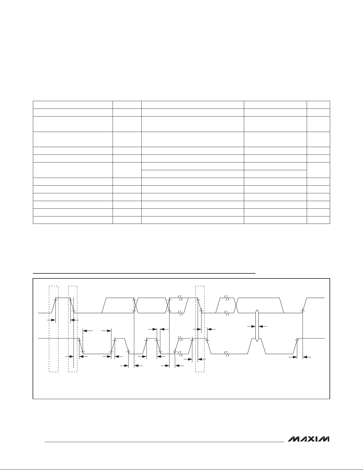
I2C/SMBus Timing
SDA
t
BUF
t
LOW
SCL
t
HD:STA
STOP START REPEATED
NOTE: TIMING IS REFERENCED TO V
IL(MAX)
AND V
t
R
IH(MIN)
t
HD:DAT
.
8
t
HIGH
t
F
t
SU:DAT
START
t
SU:STA
t
HD:STA
t
SP
t
SU:STO
Page 9
PMBus 5-Channel Power-Supply Manager
and Intelligent Fan Controller
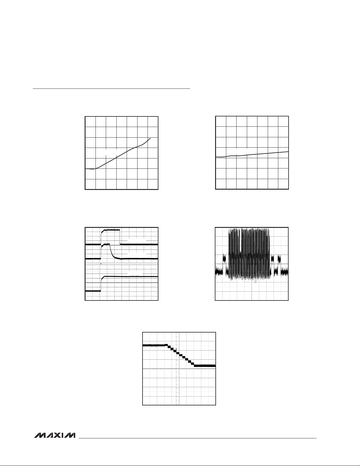
Typical Operating Characteristics
(T
= +25°C, unless otherwise noted.)
A
MAX34441
SUPPLY CURRENT vs. TEMPERATURE
2.7
2.6
2.5
2.4
(mA)
DD
I
2.3
2.2
2.1
2.0
-40 100
VDD = 3.3V
TEMPERATURE (°C)
WEAK PULLUP VOLTAGE vs. TIME AT POR
(UNLOADED PINS, V
0V
0V
1V/div
= 3.3V)
DD
C1 = PSEN0
C3 = PWM0
C2 = V
MAX34441 toc03
DD
SUPPLY CURRENT vs. SUPPLY VOLTAGE
2.7
MAX34441 toc01
806040200-20
2.6
2.5
2.4
(mA)
DD
I
2.3
2.2
2.1
2.0
2.7 5.5
TA = +25°C
VDD (V)
MAX34441 toc02
5.14.74.33.93.53.1
IDD vs. TIME DURING A FLASH WRITE
= +25°C, VDD = 3.3V)
(T
A
1mA/div
MAX34441 toc04
0V
1ms/div
0A
2ms/div
FILTERED MARGINING VOLTAGE
vs. TIME DURING MARGIN UP
200mV/div
0V
100ms/div
MAX34441 toc05
9
Page 10
PMBus 5-Channel Power-Supply Manager
and Intelligent Fan Controller
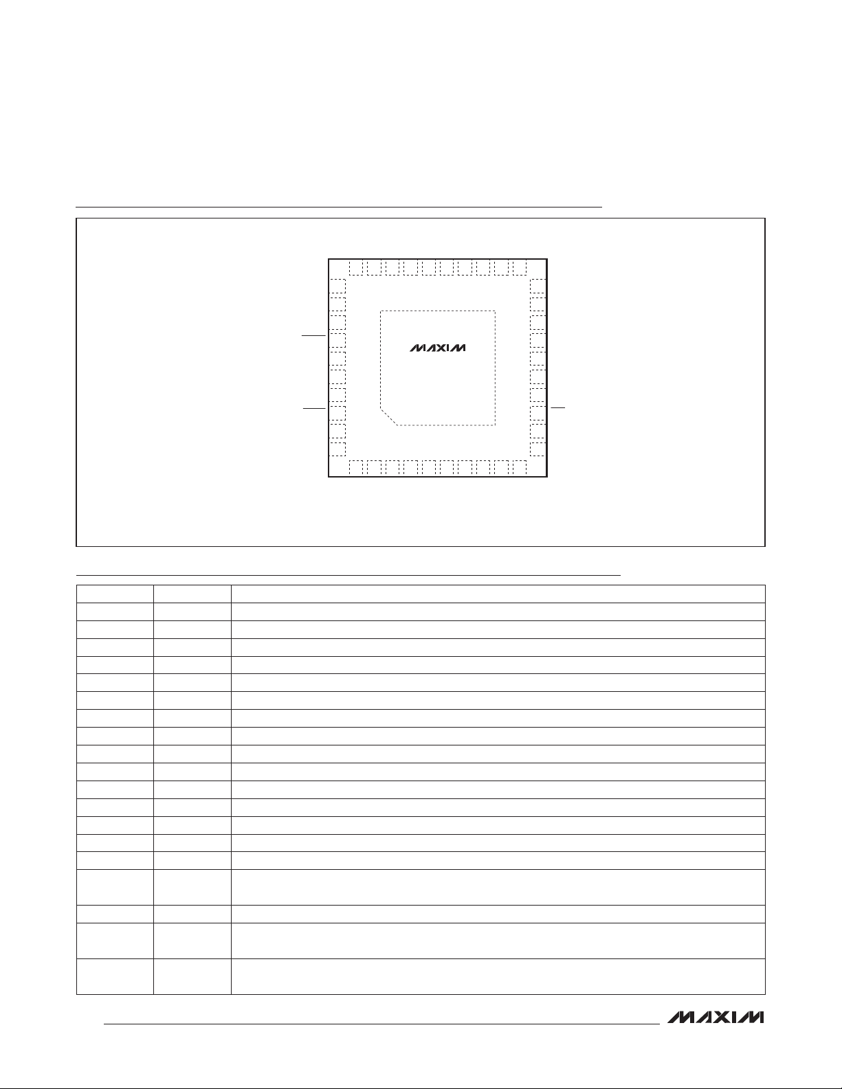
Pin Configuration
PSEN3
RS+1
REG18
21
DD
V
SS
V
RS-1
20
PWM3
19
PSEN4
18
PWM4
17
TACH5
16
PWM5
MSCL
15
14
MSDA
RST
13
12
RS-2
11
RS+2
MAX34441
TOP VIEW
SDA
SCL
A0/MUXSEL
FAULT
CONTROL
V
A1/PG/TACHSEL
ALERT
RS-5
RS+5
REG25
PSEN0
31
32
33
34
35
36
SS
37
38
39
40
+
1 2 4 5 6 7
SS
V
RS-4
PWM1
PSEN1
MAX34441
RS-3
RS+3
PSEN2
25
RS+0
PWM0
27282930 26 24 23 22
3
RS+4
PWM2
EP
8 9 10
RS-0
TQFN
(6mm × 6mm × 0.75mm)
Pin Description
PIN NAME FUNCTION
1 RS-4 Ground Reference for ADC4 Voltage Measurement
2, 21, 36 V
SS
3 RS+4 Power-Supply ADC Voltage-Sense Input, Measurement Relative to RS-4
4 RS-3 Ground Reference for ADC3 Voltage Measurement
5 RS+3 Power-Supply ADC Voltage-Sense Input, Measurement Relative to RS-3
6 RS+0 Power-Supply ADC Voltage-Sense Input, Measurement Relative to RS-0
7 RS-0 Ground Reference for ADC0 Voltage Measurement
8 RS+1 Power-Supply ADC Voltage-Sense Input, Measurement Relative to RS-1
9 V
DD
10 RS-1 Ground Reference for ADC1 Voltage Measurement
11 RS+2 Power-Supply ADC Voltage-Sense Input, Measurement Relative to RS-2
12 RS-2 Ground Reference for ADC2 Voltage Measurement
13
RST
14 MSDA Master I2C Data Input/Output. Open-drain output.
15 MSCL Master I2C Clock Output. Open-drain output.
16 PWM5
17 TACH5 Fan Tachometer Input
18 PWM4
19 PSEN4
Digital-Supply Return Node (Ground)
Supply Voltage. Bypass VDD to VSS with a 0.1FF capacitor.
Reset Active-Low Input
Fan PWM Output #5. CMOS push-pull output. Low when the fan is disabled. A 100% duty cycle
implies this pin is continuously high.
PWM Margin Output #4. High impedance when the margining is disabled. A 100% duty cycle implies
this pin is continuously high.
Power-Supply Enable Output #4. Programmable through MFR_MODE for either active high or active
low and either open drain or CMOS push-pull.
10
Page 11

PMBus 5-Channel Power-Supply Manager
and Intelligent Fan Controller
Pin Description (continued)
PIN NAME FUNCTION
20 PWM3
22 REG18
23 PSEN3
24 PWM2
25 PSEN2
26 PWM1
27 PSEN1
28 PWM0
29 REG25
30 PSEN0
31 SDA I2C/SMBus-Compatible Input/Output
32 SCL I2C/SMBus-Compatible Clock Input
33 A0/MUXSEL
34
35 CONTROL
37
38
39 RS-5 Thermal Diode ADC Voltage Negative-Sense Input, Measurement Relative to RS+5
40 RS+5 Thermal Diode ADC Voltage Positive-Sense Input, Measurement Relative to RS-5
— EP Exposed Pad (Bottom Side of Package). Connect EP to VSS.
Note: All pins except VDD, VSS, REG18, REG25, ADC, and the EP are high impedance with a 50µA pullup during device power-up
and reset. After device reset, the weak pullup is removed, and the pin is configured as input or output.
FAULT
A1/PG/
TACHSEL
ALERT
PWM Margin Output #3. High impedance when the margining is disabled. A 100% duty cycle implies
this pin is continuously high.
Regulator for Low-Voltage Digital Circuitry. Bypass REG18 to VSS with 1FF and 10nF capacitors. Do
not connect other circuitry to this pin.
Power-Supply Enable Output #3. Programmable through MFR_MODE for either active high or active
low and either open drain or CMOS push-pull.
PWM Margin Output #2. High impedance when the margining is disabled. A 100% duty cycle implies
this pin is continuously high.
Power-Supply Enable Output #2. Programmable through MFR_MODE for either active high or active
low and either open drain or CMOS push-pull.
PWM Margin Output #1. High impedance when the margining is disabled. A 100% duty cycle implies
this pin is continuously high.
Power-Supply Enable Output #1. Programmable through MFR_MODE for either active high or active
low and either open drain or CMOS push-pull.
PWM Margin Output #0. High impedance when the margining is disabled. A 100% duty cycle implies
this pin is continuously high.
Regulator for Analog Circuitry. Bypass REG25 to VSS with 1FF and 10nF capacitors. Do not connect
other circuitry to this pin.
Power-Supply Enable Output #0. Programmable through MFR_MODE for either active high or active
low and either open drain or CMOS push-pull.
SMBus Address 0 Input/Multiplexer Control Output. This dual-function pin is sampled on device
power-up to determine the SMBus address; connect a 100kI resistor from this pin to either VSS or
VDD to set the address. After device power-up, this pin becomes an output that acts as voltage/
current selector for an external analog multiplexer. MUXSEL is low for voltage measurements and
high for current measurements.
Active-Low, Open-Drain Fault Input/Output. This pin is asserted when one or more of the power supplies
in a global group are shut down due to a fault condition. Also, this pin is monitored and, when it is
asserted, all power supplies in a global group are shut down. This pin is used to provide hardware
control for power supplies in a global group across multiple devices. This output is unconditionally
deasserted when RST is asserted or the device is power cycled. This pin has a 50Fs deglitch filter.
Device Enable. Option through ON_OFF_CONFIG for active-low or active-high power-supply control.
This pin has a 50Fs deglitch filter.
SMBus Address 1 Input/Power-Good Output. This triple-function pin is sampled on device powerup to determine the SMBus address; connect a 100kI resistor from this pin to either VSS or VDD to
set the address. After device power-up, this pin becomes an output that transitions high when all
the enabled power supplies are above their associated POWER_GOOD_ON thresholds. Alternately,
this pin can be programmed through MFR_MODE to select between two tachometers in dual-fan
applications.
Active-Low, Open-Drain Alert Output
MAX34441
11
Page 12
PMBus 5-Channel Power-Supply Manager
and Intelligent Fan Controller
Block Diagram
MAX34441
V
V
REG25
V
REG18
V
MSDA
MSCL
SDA
SCL
RST
ALERT
FAULT
CONTROL
A0/MUXSEL
A1/PG/TACHSEL
DD
SS
SS
SS
POWER
CONTROL
2.5V
VREG
1.8V
VREG
4MHz
OSCILLATOR
SMBus
MASTER
INTERFACE
SMBus
SLAVE
INTERFACE
SYSTEM
CONTROL
SIGNALS
MAX34441
16-BIT
MAXQ
RISC CORE
PULSE-
WIDTH
MODULATOR
POWERSUPPLY
OUTPUT
ENABLES
FAN
TACHOMETER
INPUT
ADC
MUX
FLASHRAM
TEMP
SENSOR
PWM0
PWM1
PWM2
PWM3
PWM4
PWM5
PSEN0
PSEN1
PSEN2
PSEN3
PSEN4
TACH5
RS+0
RS-0
RS+1
RS-1
RS+2
RS-2
RS+3
RS-3
RS+4
RS-4
RS+5
RS-5
12
Page 13
PMBus 5-Channel Power-Supply Manager
and Intelligent Fan Controller
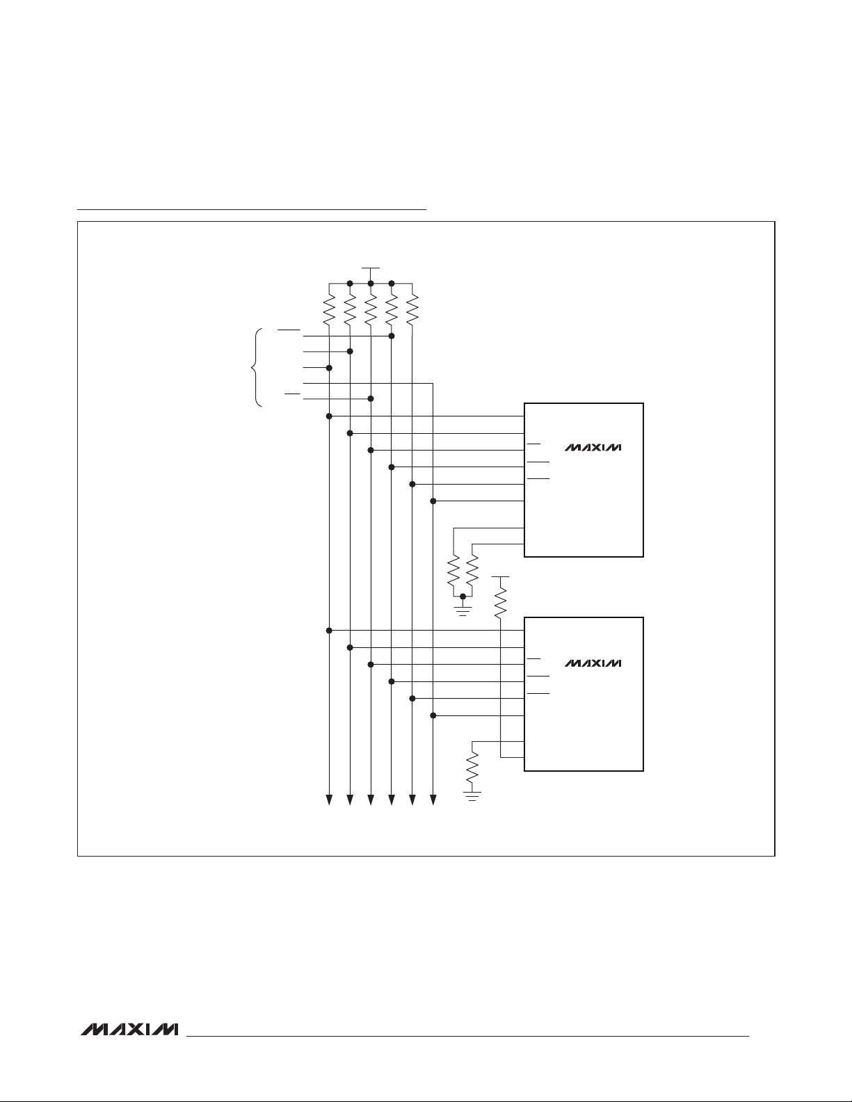
Multiple Device Connection Diagram
+3.3V
ALERT
HOST
INTERFACE
CLOCK
DATA
CONTROL
RST
SDA
SCL
RST
ALERT
FAULT
CONTROL
A1/PG/TACHSEL
A0/MUXSEL
MAX34441
#0
MAX34441
ADDITIONAL DEVICES
+3.3V
SDA
SCL
RST
ALERT
FAULT
CONTROL
A1/PG/TACHSEL
A0/MUXSEL
MAX34441
#1
13
Page 14
PMBus 5-Channel Power-Supply Manager
and Intelligent Fan Controller
Detailed Description
The MAX34441 is a highly integrated system monitor
based upon a 4MHz, 16-bit, MAXQM microcontroller with
factory-programmed functionality to monitor up to five
power supplies and a system cooling fan. The device
provides power-supply closed-loop control, fan-speed
monitoring, and local/remote thermal-sensing facilities.
The power-supply manager monitors the power-supply
output voltage and constantly checks for user-pro-
MAX34441
grammable overvoltage and undervoltage thresholds. It
also can margin the power-supply output voltage up or
down by a user-programmable level. The margining is
performed in a closed-loop arrangement, whereby the
device automatically adjusts a pulse-width-modulated
(PWM) output and then measures the resultant output
voltage. The power-supply manager can also sequence
the supplies in any order at both power-up and powerdown. With the addition of an external current-sense
Thermal monitoring can be accomplished using up to six
temperature sensors, including an on-chip thermal sensor, four DS75LV digital thermometers, and a remote thermal diode. Temperature offset can be added to individual
sensors to compensate for thermal differences in a system. Communication with the DS75LV temperature sensor
is conducted through a dedicated I2C/SMBus interface.
The device also contains closed-loop fan-speed control.
Based on user-programmable settings for fan-control
PWM duty cycles or for fan RPM speeds at particular temperature breakpoints, the device automatically
adjusts the fan speed in a manner to reduce audible
noise and power consumption.
The device provides ALERT and FAULT output signals.
Host communications are conducted through a PMBuscompatible communications port. Address input connections are also provided to allow up to four MAX34441
devices to reside on the system’s I/O bus.
amplifier, the device can also monitor currents.
Table 1. PMBus Command Codes
PAGE
CODE COMMAND NAME TYPE
00h PAGE R/W Byte R/W R/W R/W R/W 1 N 00h
01h OPERATION R/W Byte R/W — — W 1 N 00h
02h ON_OFF_CONFIG R/W Byte R/W R/W R/W R/W 1 Y 1Ah
03h CLEAR_FAULTS Send Byte W W W W 0 N —
10h WRITE_PROTECT R/W Byte R/W R/W R/W R/W 1 N 00h
11h STORE_DEFAULT_ALL Send Byte W W W W 0 N —
12h RESTORE_DEFAULT_ALL Send Byte W W W W 0 N —
19h CAPABILITY Read Byte R R R R 1 N 00h/10h
20h VOUT_MODE Read Byte R R R R 1 FIXED 40h
25h VOUT_MARGIN_HIGH R/W Word R/W — — — 2 Y 0000h
26h VOUT_MARGIN_LOW R/W Word R/W — — — 2 Y 0000h
2Ah VOUT_SCALE_MONITOR R/W Word R/W — — — 2 Y 7FFFh
38h IOUT_CAL_GAIN R/W Word R/W — — — 2 Y 0000h
3Ah FAN_CONFIG_1_2 R/W Byte — R/W — — 1 Y 00h
3Bh FAN_COMMAND_1 R/W Word — R/W — — 2 Y FFFFh
40h VOUT_OV_FAULT_LIMIT R/W Word R/W — — — 2 Y 7FFFh
42h VOUT_OV_WARN_LIMIT R/W Word R/W — — — 2 Y 7FFFh
43h VOUT_UV_WARN_LIMIT R/W Word R/W — — — 2 Y 0000h
44h VOUT_UV_FAULT_LIMIT R/W Word R/W — — — 2 Y 0000h
46h IOUT_OC_WARN_LIMIT R/W Word R/W — — — 2 Y 7FFFh
4Ah IOUT_OC_FAULT_LIMIT R/W Word R/W — — — 2 Y 0000h
4Fh OT_FAULT_LIMIT R/W Word — — R/W — 2 Y 7FFFh
0–4
PAGE5PAGE
6–11
(NOTE 1)
PAGE
255
NO. OF
BYTES
FLASH
STORED
(NOTE 2)
DEFAULT
VALUE
(NOTE 2)
MAXQ is a registered trademark of Maxim Integrated
Products, Inc.
14
Page 15

PMBus 5-Channel Power-Supply Manager
and Intelligent Fan Controller
Table 1. PMBus Command Codes (continued)
PAGE
CODE COMMAND NAME TYPE
51h OT_WARN_LIMIT R/W Word — — R/W — 2 Y 7FFFh
5Eh POWER_GOOD_ON R/W Word R/W — — — 2 Y 0000h
5Fh POWER_GOOD_OFF R/W Word R/W — — — 2 Y 0000h
60h TON_DELAY R/W Word R/W — — — 2 Y 0000h
62h TON_MAX_FAULT_LIMIT R/W Word R/W — — — 2 Y 0000h
64h TOFF_DELAY R/W Word R/W — — — 2 Y 0000h
78h STATUS_BYTE Read Byte R R R R 1 N 00h
79h STATUS_WORD Read Word R R R R 2 N 0000h
7Ah STATUS_VOUT Read Byte R — — — 1 N 00h
7Eh STATUS_CML Read Byte R R R R 1 N 00h
80h STATUS_MFR_SPECIFIC Read Byte R — R — 1 N 00h
81h STATUS_FANS_1_2 Read Byte — R — — 1 N 00h
8Bh READ_VOUT Read Word R — — — 2 N 0000h
8Ch READ_IOUT Read Word R — — — 2 N 0000h
8Dh READ_TEMPERATURE_1 Read Word — — R — 2 N 0000h
90h READ_FAN_SPEED_1 Read Word — R — — 2 N 0000h
98h PMBUS_REVISION Read Byte R R R R 1 FIXED 11h
99h MFR_ID Read Byte R R R R 1 FIXED 4Dh
9Ah MFR_MODEL Read Byte R R R R 1 FIXED 52h
9Bh MFR_REVISION Read Word R R R R 2 FIXED 3030h
9Ch MFR_LOCATION Block R/W R/W R/W R/W R/W 8 Y (Note 3)
9Dh MFR_DATE Block R/W R/W R/W R/W R/W 8 Y (Note 3)
9Eh MFR_SERIAL Block R/W R/W R/W R/W R/W 8 Y (Note 3)
D1h MFR_MODE R/W Word R/W R/W R/W R/W 2 Y 0000h
D4h MFR_VOUT_PEAK R/W Word R/W — — — 2 N 0000h
D5h MFR_IOUT_PEAK R/W Word R/W — — — 2 N 0000h
D6h MFR_TEMPERATURE_PEAK R/W Word — — R/W — 2 N 8000h
D7h MFR_VOUT_MIN R/W Word R/W — — — 2 N 7FFFh
D9h MFR_FAULT_RESPONSE R/W Word R/W — — — 2 Y 0000h
DAh MFR_FAULT_RETRY R/W Word R/W R/W R/W R/W 2 Y 0000h
DCh MFR_NV_FAULT_LOG Block Read R R R R 255 Y (Note 4)
DDh MFR_TIME_COUNT Block Read R R R R 4 N (Note 5)
E0h MFR_MARGIN_CONFIG R/W Word R/W — — — 2 Y 0000h
F0h MFR_TEMP_SENSOR_CONFIG R/W Word — — R/W — 2 Y 0000h
F1h MFR_FAN_CONFIG R/W Word — R/W — — 2 Y 0000h
F2h MFR_FAN_LUT Block R/W — R/W — — 32 Y (Note 6)
F3h MFR_READ_FAN_PWM Read Word — R — — 2 N 0000h
F5h MFR_FAN_FAULT_LIMIT R/W Word — R/W — — 2 Y 0000h
F6h MFR_FAN_WARN_LIMIT R/W Word — R/W — — 2 Y 0000h
Note 1: Common commands are shaded. Access through any page results in the same device response.
Note 2: In the Flash Stored column, an “N” indicates that this parameter is not stored in flash memory when the STORE_
DEFAULT_ALL command is executed and the value shown in the Default Value column is automatically loaded upon
power-on reset or when the RST pin is asserted. A “Y” in the Flash Stored column indicates that the currently loaded value
in this parameter is stored in flash memory when the STORE_DEFAULT_ALL command is executed and is automatically
0–4
PAGE5PAGE
6–11
(NOTE 1)
PAGE
255
NO. OF
BYTES
FLASH
STORED
(NOTE 2)
DEFAULT
VALUE
(NOTE 2)
MAX34441
15
Page 16
PMBus 5-Channel Power-Supply Manager
and Intelligent Fan Controller
Table 1. PMBus Command Codes (continued)
loaded upon power-on reset or when the RST pin is asserted and the value shown in the Default Value column is the
value when shipped from the factory. “FIXED” in the Flash Stored column means this value is fixed at the factory and
cannot be changed.
Note 3: The factory-set default value for this 8-byte block is 3130313031303130h.
Note 4: The factory-set default value for the complete block of the MFR_NV_FAULT_LOG is FFh.
Note 5: The power-on reset value for this 4-byte block is 00000000h.
Note 6: The factory-set default value for the complete block of the MFR_FAN_LUT is 00h.
MAX34441
Table 2. PMBus/SMBus Serial-Port
Address
A1 A0
100kI to V
100kI to V
SS
DD
100kI to V
100kI to V
100kI to V
100kI to V
READ WORD FORMAT
1 7 1 1 8 1 1 7 1 1 8 1 8 1 1
SLAVE
S
ADDRESS
W A
READ BYTE FORMAT
1 7 1 1 8 1 1 7 1 1 8 1 1
SLAVE
S
ADDRESS
W A
SS
DD
SS
DD
COMMAND
CODE
COMMAND
CODE
7-BIT SLAVE
ADDRESS
1101 010 (D4h)
1101 011 (D6h)
1101 100 (D8h)
1101 101 (DAh)
A Sr
A Sr
Address Select
On device power-up, the device samples the A0 and A1
pins to determine the PMBus/SMBus serial-port address.
SMBus/PMBus Operation
The device implements the PMBus command structure
using the SMBus format. The structure of the data flow
between the host and the slave is shown below for several different types of transactions. All transactions begin
with a host sending a command code that is immediately
preceded with a 7-bit slave address (R/W = 0). Data is
sent most significant bit (MSB) first.
SMBus/PMBus Communication Examples
SLAVE
ADDRESS
SLAVE
ADDRESS
R A
R A DATA BYTE NA P
DATA BYTE
LOW
A
DATA BYTE
HIGH
NA P
WRITE WORD FORMAT
1 7 1 1 8 1 8 1 8 1 1
S
SLAVE
ADDRESS
W A
COMMAND
CODE
DATA BYTE
A
LOW
A
DATA BYTE
HIGH
WRITE BYTE FORMAT
1 7 1 1 8 1 8 1 1
S
SLAVE
ADDRESS
W A
COMMAND
CODE
A DATA BYTE A P
SEND BYTE FORMAT
1 7 1 1 8 1 1
16
S
SLAVE
ADDRESS
W A
COMMAND
CODE
A P
A P
KEY:
S = START
Sr = REPEATED START
P = STOP
W = WRITE BIT (0)
R = READ BIT (1)
A = ACKNOWLEDGE (0)
NA = NOT ACKNOWLEDGE (1)
SHADED BLOCK = SLAVE TRANSACTION
Page 17

PMBus 5-Channel Power-Supply Manager
and Intelligent Fan Controller
Group Command
The device supports the group command. With the
group command, a host can write different data to
multiple devices on the same serial bus with one long
SLAVE ADDRESS, COMMAND BYTE, AND DATA WORD FOR DEVICE 1
1 7 1 1 8 1 8 1 8 1
S
SLAVE
ADDRESS
W A
COMMAND
CODE
DATA BYTE
A
LOW
SLAVE ADDRESS, COMMAND BYTE, AND DATA BYTE FOR DEVICE 2
1 7 1 1 8 1 8 1
Sr
SLAVE
ADDRESS
W A
COMMAND
CODE
A DATA BYTE A U U U
SLAVE ADDRESS AND SEND BYTE FOR DEVICE 3
1 7 1 1 8 1
Sr
U U U
SLAVE
ADDRESS
W A
COMMAND
CODE
A U U U
continuous data stream. All the devices addressed during this transaction wait for the host to issue a STOP
before beginning to respond to the command.
DATA BYTE
A
HIGH
MAX34441
Group Command Write Format
A U U U
KEY:
S = START
Sr = REPEATED START
P = STOP
W = WRITE BIT (0)
A = ACKNOWLEDGE (0)
SHADED BLOCK = SLAVE TRANSACTION
SLAVE ADDRESS, COMMAND BYTE, AND DATA WORD FOR DEVICE N
1 7 1 1 8 1 8 1 8 1 1
SLAVE
Sr
ADDRESS
W A
The device responds to receiving its fixed slave address
by asserting an acknowledge (ACK) on the bus. The
device does not respond to a general call address; it
only responds when it receives its fixed slave address.
The only exception to this operation is if the ALERT
output is enabled (ALERT bit = 1 in MFR_MODE) and
ALERT has been asserted. When this condition occurs,
the device only recognizes the alert response address
(0001 100, 18h). See the ALERT and Alert Response
Address (ARA) section for more details.
ALERT and Alert Response Address (ARA)
If the ALERT output is enabled (ALERT bit = 1 in
MFR_MODE), when a fault occurs the device asserts the
COMMAND
CODE
Addressing
DATA BYTE
A
LOW
DATA BYTE
A
HIGH
response address (ARA) as shown in the Alert Response
Address (ARA) Byte Format section. While waiting for
the ARA, the device does not respond to its fixed
slave address.
When the ARA is received and the device is asserting
ALERT, the device ACKs it and then attempts to place
its fixed slave address on the bus by arbitrating the
bus, since another device could also try to respond to
the ARA. The rules of arbitration state that the lowest
address device wins. If the device wins the arbitration,
it deasserts ALERT and begins to respond to its fixed
slave address. If the device loses arbitration, it keeps
ALERT asserted and waits for the host to once again
send the ARA.
ALERT signal and then waits for the host to send the alert
A P
17
Page 18

PMBus 5-Channel Power-Supply Manager
and Intelligent Fan Controller
Alert Response Address (ARA) Byte Format
1 7 1 1 8 1 1
S
ARA
0001100
R A
DEVICE SLAVE ADDRESS
WITH LSB = 0
NA P
MAX34441
If for any reason the host does not complete writing a full
byte or reading a full byte from the device before a START
or STOP is received, the device does the following:
1) Ignores the command.
2) Sets the CML bit in STATUS_BYTE.
3) Sets the CML bit in STATUS_WORD.
4) Sets the DATA_FAULT bit in STATUS_CML.
5) Notifies the host through ALERT assertion (if enabled).
Host Sends or Reads Too Few Bytes
Host Sends or Reads Too Few Bits
For each supported command, the device expects a
fixed number of bytes to be written or read from the
device. If for any reason fewer than the expected number
of bytes is written to or read from the device, the device
completely ignores the command and takes no action.
Host Sends Too Many Bytes or Bits
For each supported command, the device expects a
fixed number of bytes to be written to the device. If for
any reason more than the expected number of bytes or
bits is written to the device, the device does the following:
1) Ignores the command.
2) Sets the CML bit in STATUS_BYTE.
3) Sets the CML bit in STATUS_WORD.
4) Sets the DATA_FAULT bit in STATUS_CML.
5) Notifies the host through ALERT assertion (if enabled).
Host Reads Too Many Bytes or Bits
For each supported command, the device expects a fixed
number of bytes to be read from the device. If for any
reason more than the expected number of bytes or bits is
read from the device, the device does the following:
1) Sends all ones (FFh) as long as the host keeps
acknowledging.
2) Sets the CML bit in STATUS_BYTE.
3) Sets the CML bit in STATUS_WORD.
4) Sets the DATA_FAULT bit in STATUS_CML.
5) Notifies the host through ALERT assertion (if enabled).
Host Sends Improperly Set Read Bit
in the Slave Address Byte
If the device receives the R/W bit in the slave address
set to one immediately preceding the command code,
the device does the following (note this does not apply
to ARA):
1) ACKs the address byte.
2) Sends all ones (FFh) as long as the host keeps
acknowledging.
3) Sets the CML bit in STATUS_BYTE.
4) Sets the CML bit in STATUS_WORD.
5) Sets the DATA_FAULT bit in STATUS_CML.
6) Notifies the host through ALERT assertion (if enabled).
Unsupported Command Code Received
If the host sends the device a command code that it
does not support, or if the host sends a command code
that is not supported by the current PAGE setting, the
device does the following:
1) Ignores the command.
2) Sets the CML bit in STATUS_BYTE.
3) Sets the CML bit in STATUS_WORD.
4) Sets the COMM_FAULT bit in STATUS_CML.
5) Notifies the host through ALERT assertion (if enabled).
Invalid Data Received
The device checks the PAGE, OPERATION, and
WRITE_PROTECT command codes for valid data. If the
host writes a data value that is invalid, the device does
the following:
1) Ignores the command.
2) Sets the CML bit in STATUS_BYTE.
3) Sets the CML bit in STATUS_WORD.
4) Sets the DATA_FAULT bit in STATUS_CML.
5) Notifies the host through ALERT assertion (if enabled).
18
Page 19

PMBus 5-Channel Power-Supply Manager
and Intelligent Fan Controller
Host Reads from a Write-Only Command
When a read request is issued to a write-only
command (CLEAR_FAULTS, STORE_DEFAULT_ALL,
RESTORE_DEFAULT_ALL), the device does the following:
1) ACKs the address byte.
2) Ignores the command.
3) Sends all ones (FFh) as long as the host keeps
acknowledging.
4) Sets the CML bit in STATUS_BYTE.
5) Sets the CML bit in STATUS_WORD.
6) Sets the DATA_FAULT bit in STATUS_CML.
7) Notifies the host through ALERT assertion (if enabled).
Host Writes to a Read-Only Command
When a write request is issued to a read-only command,
the device does the following:
1) Ignores the command.
2) Sets the CML bit in STATUS_BYTE.
3) Sets the CML bit in STATUS_WORD.
4) Sets the COMM_FAULT bit in STATUS_CML.
5) Notifies the host through ALERT assertion (if enabled).
SMBus Timeout
If during an active SMBus communication sequence
the SCL signal is held low for greater than the timeout
duration (nominally 30ms), the device terminates the
sequence and resets the serial bus. It takes no other
action. No status bits are set.
PMBus Operation
From a software perspective, the device appears as a
PMBus device capable of executing a subset of PMBus
commands. A PMBus 1.1-compliant device uses the
SMBus version 1.1 for transport protocol and responds
to the SMBus slave address. In this data sheet, the term
SMBus is used to refer to the electrical characteristics
of the PMBus communication using the SMBus physical layer. The term PMBus is used to refer to the PMBus
command protocol. The device employs a number of
standard SMBus protocols such as Write Word, Read
Word, Write Byte, Read Byte, Send Byte, and so on to
program output voltage and warning/faults thresholds,
read monitored data, and provide access to all manufacturer-specific commands.
The device supports the group command. The group
MAX34441
command is used to send commands to more than one
PMBus device. It is not required that all the devices
receive the same command. However, no more than
one command can be sent to any one device in one
group command packet. The group command must not
be used with commands that require receiving devices
to respond with data, such as the STATUS_BYTE command. When the device receives a command through
this protocol, it immediately begins execution of the
received command after detecting the STOP condition.
The device supports the PAGE command and uses it to
select which individual channel to access. When a data
word is transmitted, the lower order byte is sent first and
the higher order byte is sent last. Within any byte, the
most significant bit (MSB) is sent first and the least significant bit (LSB) is sent last.
PMBus Protocol Support
The device supports a subset of the commands defined
in the PMBus™ Power System Management Protocol
Specification Part II - Command Language, Revision 1.1.
For detailed specifications and the complete list of
PMBus commands, refer to Part II of the PMBus specification available at www.PMBus.org. The supported
PMBus commands and the corresponding device behavior are described in this document. All data values are
represented in DIRECT format, unless otherwise stated.
Whenever the PMBus specification refers to the PMBus
device, it is referring to the MAX34441 operating in conjunction with a power supply or fan. While the command
can call for turning on or turning off the PMBus device,
the MAX34441 always remains on to continue communicating with the PMBus master, and the MAX34441
transfers the command to the power supply accordingly.
Data Format
Voltage data for commanding or reading the output
voltage or related parameters (such as the overvoltage threshold) is presented in DIRECT format. DIRECT
format data is a 2-byte, two’s complement binary value.
DIRECT format data can be used with any command that
sends or reads a parametric value. The DIRECT format
uses an equation and defined coefficients to calculate
the desired values. Table 3 shows the coefficients used
by the device.
19
Page 20

PMBus 5-Channel Power-Supply Manager
and Intelligent Fan Controller
Table 3. PMBus Command Code Coefficients
PARAMETER COMMANDS UNITS RESOLUTION MAX m b R
VOUT_MARGIN_HIGH
VOUT_MARGIN_LOW
VOUT_OV_FAULT_LIMIT
VOUT_OV_WARN_LIMIT
VOUT_UV_WARN_LIMIT
Voltage
MAX34441
Voltage Scaling VOUT_SCALE_MONITOR — 1/32,767 1 32,767 0 0
Current
Current Scaling IOUT_CAL_GAIN
Temperature
Fan Speed
Timing
VOUT_UV_FAULT_LIMIT
POWER_GOOD_ON
POWER_GOOD_OFF
READ_VOUT
MFR_VOUT_PEAK
MFR_VOUT_MIN
IOUT_OC_WARN_LIMIT
IOUT_OC_FAULT_LIMIT
READ_IOUT
MFR_IOUT_PEAK
OT_FAULT_LIMIT
OT_WARN_LIMIT
READ_TEMPERATURE_1
MFR_TEMPERATURE_PEAK
READ_FAN_SPEED_1
FAN_COMMAND_1
MFR_FAN_FAULT_LIMIT
MFR_FAN_WARN_LIMIT
FAN_COMMAND_1
MFR_READ_FAN_PWM
MFR_FAN_FAULT_LIMIT
MFR_FAN_WARN_LIMIT
TON_DELAY
TON_MAX_FAULT_LIMIT
TOFF_DELAY
MFR_FAULT_RETRY
mV 1 32,767 1 0 0
mA 1 32,767 1 0 0
mI
NC
RPM 1 32,767 1 0 0
% 0.01 327.67 1 0 2
ms 1 32,767 1 0 0
0.1 3276.7 1 0 1
0.01 327.67 1 0 2
Interpreting Received
DIRECT Format Values
The host system uses the following equation to convert
the value received from the PMBus device—in this case,
the MAX34441—into a reading of volts, degrees Celsius,
or other units as appropriate:
X = (1/m) x (Y x 10-R - b)
where X is the calculated, real world value in the appropriate units (V, NC, etc.); m is the slope coefficient; Y is
the 2-byte, two’s complement integer received from the
PMBus device; b is the offset; and R is the exponent.
20
Sending a DIRECT Format Value
To send a value, the host must use the below equation
to solve for Y:
Y = (mX + b) x 10
R
where Y is the 2-byte, two’s complement integer to be
sent to the unit; m is the slope coefficient; X is the real
world value, in units such as volts, to be converted for
transmission; b is the offset; and R is the exponent.
Page 21

PMBus 5-Channel Power-Supply Manager
and Intelligent Fan Controller
The following example demonstrates how the host can
send and retrieve values from the device. Table 4 shows
the coefficients used in the following parameters.
Table 4. Coefficients for DIRECT Format
Value
COMMAND
CODE
25h VOUT_MARGIN_HIGH 1 0 0
8Bh READ_VOUT 1 0 0
If a host wants to set the device to change the powersupply output voltage to 3.465V (or 3465mV), the corresponding VOUT_MARGIN_HIGH value is:
Y = (1 x 3465 + 0) x 100 = 3465 (decimal) = 0D89h (hex)
Conversely, if the host received a value of 0D89h on a
READ_VOUT command, this is equivalent to:
X = (1/1) x (0D89h x 10
Power supplies and power converters generally have
no way of knowing how their outputs are connected to
ground. Within the power supply, all output voltages are
most commonly treated as positive. Accordingly, all output voltages and output voltage-related parameters of
PMBus devices are commanded and reported as positive values. It is up to the system to know that a particular
output is negative if that is of interest to the system. All
output-voltage-related commands use 2 data bytes.
For reporting faults/warnings to the host on a real-time
basis, the device asserts the open-drain ALERT pin (if
enabled in MFR_MODE) and sets the appropriate bit in
the various status registers. On recognition of the ALERT
assertion, the host or system manager is expected to poll
the I2C bus to determine the device asserting ALERT.
COMMAND NAME m b R
-(-0)
- 0) = 3465mV = 3.465V
Fault Management and Reporting
The host sends the SMBus ARA (0001 100). The device
MAX34441
ACKs the SMBus ARA, transmits its slave address, and
deasserts ALERT. The system controller then communicates with PMBus commands to retrieve the fault/warning status information from the device.
See the individual command sections for more details.
Faults and warnings that are latched in the status registers are cleared when any one of the following conditions
occurs:
• ACLEAR_FAULTScommandisreceived.
• TheRST pin is toggled.
• Biaspowertothedeviceisremovedandthenreapplied.
One or more latched-off power supplies is only restarted
when one of the following occurs:
• The output is commanded through the CONTROL
pin, the OPERATION command, to turn off and then
turn back on.
• TheRST pin is toggled.
• Biaspowertothedeviceisremovedandthenreapplied.
A power supply is not allowed to turn on if any faults the
supply responds to are detected. Only after the faults
clear is the power supply allowed to turn on. When global
supplies are being sequenced on, a fault on any of the
supplies keeps all supplies from being turned on.
A system-wide power-up (OPERATION command is
received to turn the supplies on when PAGE is 255 or the
CONTROL pin is toggled to turn on the supplies) allows
all enabled power supplies to power-up. If any faults are
detected once the supplies start to turn on, the response
of MFR_FAULT_RESPONSE is performed.
The device responds to fault conditions according to the manufacturer fault response command
(MFR_FA ULT_RESPONSE). This command byte
determines how the device should respond to each
Table 5. Device Parametric Monitoring States
PARAMETER REQUIRED CONDITIONS FOR ACTIVE MONITORING ACTION DURING A FAULT
Overvoltage
Undervoltage
Overcurrent
Power-Up Time
Overtemperature Temp Sensor Enabled (ENABLE in MFR_TEMP_SENSOR_CONFIG = 1) Continue Monitoring
Fan Speed Fan Enabled (Bit 7 in FAN_CONFIG_1_2 = 1) Continue Monitoring
Power Supply Enabled (TON_MAX_FAULT_LIMIT ≠ 0000h)
• Power Supply Enabled (TON_MAX_FAULT_LIMIT ≠ 0000h)
• PSEN Output is Active
• Channel’s VOUT > POWER_GOOD_ON
• Power Supply Enabled (TON_MAX_FAULT_LIMIT ≠ 0000h)
• Current Monitoring Enabled (IOUT_OC_FAULT_LIMIT ≠ 0000h)
Power Supply Enabled (TON_MAX_FAULT_LIMIT ≠ 0000h)
Continue Monitoring
Stop Monitoring While the
Power Supply is Off
Continue Monitoring
Monitor Only During Power-On
21
Page 22

PMBus 5-Channel Power-Supply Manager
and Intelligent Fan Controller
particular fault. Table 5 illustrates the required conditions and fault actions for specific parameters.
System Watchdog Timer
The device uses an internal watchdog timer that is internally reset every 5ms. In the event that the device is
locked up and this watchdog reset does not occur after
500ms, the device automatically resets. After the reset
occurs, the device reloads all configuration values that
were stored to flash and begins normal operation. After
MAX34441
the reset, the device also does the following:
1) Sets the NONE OF THE ABOVE bit in STATUS_BYTE.
2) Sets the NONE OF THE ABOVE and MFR bits in
STATUS_WORD.
3) Sets the WATCHDOG bit in STATUS_MFR_SPECIFIC.
4) Notifies the host through ALERT assertion (if enabled
in MFR_MODE).
Temperature Sensor Operation
The device can monitor up to six different temperature
sensors. It can monitor up to four remote I2C-based temperature sensors plus a remote diode and its own internal
temperature sensor. Each of the enabled temperature
sensors is measured once a second. The remote diode
and internal temperature sensors are averaged four
times to reduce the affect of noise. Each time the device
attempts to read a temperature sensor it checks for
faults. For the remote diode, a fault is defined as reading
greater than +160NC or less than -60NC. For the internal
temperature sensor, a fault is defined as reading greater
than +130NC or less than -60NC. For the I2C temperature
sensors, a fault is defined as a communication access
failure. Temperature sensor faults are reported by setting the temperature reading to 7FFFh. A temperature
sensor fault results in the setting of the TEMPERATURE
bit in STATUS_BYTE and STATUS_WORD and ALERT is
asserted (if enabled in MFR_MODE). No bits are set in
STATUS_MFR_SPECIFIC.
The temperatures do not have to be used to control the
fan speed. They can be enabled and used for temperature monitoring only. Reading disabled temperature sensors returns a fixed value of 0000h.
The remote diode temperature sensor can support either
npn or pnp transistors. The device automatically cancels
the series resistance that can affect remote diodes that
are located far from the device.
The device can control up to four DS75LV digital temperature sensors. The A0, A1, and A2 pins on the DS75LV
Table 6. DS75LV Address Pin
Configurations
PAGE
7 TEMP SENSOR I2C 0 0 0 0
8 TEMP SENSOR I2C 1 0 0 1
9 TEMP SENSOR I2C 2 0 1 0
10 TEMP SENSOR I2C 3 0 1 1
should be configured as shown in Table 6. The thermostat function on the DS75LV is not used and thus the O.S.
output should be left open circuit.
MAX34441 I2C
TEMP SENSOR
DS75LV ADDRESS PIN
CONFIGURATION
A2 A1 A0
Fan Control Operation
Fan control has four operational modes. The mode is
determined by the combination of FAN_COMMAND_1
and bit 6 of FAN_CONFIG_1_2 (see Table 7). Fan control
can be disabled by setting bit 7 in FAN_CONFIG_1_2 to
zero.
Dual Fan Applications
In dual fan applications operating in RPM mode, the
tachometer selected when TACHSEL = 0 is closeloop-controlled to the target RPM. Once PWM ramping is complete, TACHSEL toggles between the two
tachometers every 500ms for monitoring purposes. The
slower of the two tachometer signals is reported by
READ_FAN_SPEED_1 and is used as a comparison for
fan faults and warning. In dual fan applications operating
in PWM mode, TACHSEL always switches every 500ms.
If one of the two tachometer signals operate at a slower
speed, it is recommended that the slower tachometer be
presented to the TACH input when TACHSEL = 0.
Automatic Fan Control Operation
In the automatic mode, the fan is controlled in a closed
loop based on the controlling temperature (the highest
postnormalized temperature reading) and the associated fan control PWM duty cycle (in %) or fan speed
(in RPM). These parameters are assigned in the fan
lookup table (LUT). See the MFR_FAN_LUT description
for configuration details. When a controlling temperature
exceeds the temperature level programmed in the LUT,
the device outputs a PWM duty cycle or adjusts the fan
speed, associated with that temperature. See Figure 1
for an example.
22
Page 23

PMBus 5-Channel Power-Supply Manager
and Intelligent Fan Controller
Table 7. Fan Control Operation Modes
FAN CONTROL
MODE
Manual PWM
External host controls the fan speed by directly setting the fan
PWM duty cycle values.
External host controls the fan speed by setting target fan speed
Manual RPM
values. The device reads the actual fan speed, and close loop
adjusts the output fan PWM to match the target fan speed.
The device sets the output PWM based on the fan LUT that
Automatic PWM
maps the temperature sensor readings to the required fan PWM
duty-cycle values.
The device reads the actual fan speed and close loop adjusts
Automatic RPM
the output fan PWM to match the target fan speed based on
the fan LUT that maps the temperature sensor readings to the
required fan speed.
Note: The RPM modes should only be used with fans that provide a tachometer output.
FAN OPERATIONAL DETAILS
OFFSET ADJUSTMENT
ALLOWS TEMPERATURE
ZONE NORMALIZATION
BIT 6 OF
FAN_CONFIG_1_2
0 0000h to 7FFFh
1 0000h to 7FFFh
0 8000h to FFFFh
1 8000h to FFFFh
MAX34441
VALUE IN
FAN_COMMAND_1
PAGE 7
PAGE 8
PAGE 9
PAGE 10
PAGE 11
PAGE 6
I2C REMOTE
TEMP SENSOR 0
I2C REMOTE
TEMP SENSOR 1
I2C REMOTE
TEMP SENSOR 2
I2C REMOTE
TEMP SENSOR 3
REMOTE DIODE
TEMP SENSOR
INTERNAL
TEMP SENSOR
Figure 1. Automatic Fan Control
+15°C
+10°C
0°C
0°C
+5°C
+5°C
FAN 8 LEVEL
LOOKUP TABLE
FAN
HIGHEST TEMPERATURE
CONTROLS THE FAN
23
Page 24

PMBus 5-Channel Power-Supply Manager
and Intelligent Fan Controller
One or all of the six available temperature sensors can
be used to control the fan speed. Each temperature
sensor has an offset adjustment that allows monitoring specific temperature zones with different thermal
characteristics. In Figure 1, I2C temperature sensor 0 is
monitoring a zone that is 15NC more sensitive than the
zone that the I2C temperature sensor 3 is measuring.
To keep the audible noise and fan power consumption
as low as possible, the device allows each temperature
MAX34441
sensor to have a temperature offset added. This allows
temperature zones with different thermal profiles to control the fan at the lowest possible speed to maintain the
required temperature.
If no temperature sensors are assigned to control the fan,
the output fan PWM signal is ramped to 100% duty cycle.
In Figure 2, at temperature sample 1, the required fan
speed is at the level associated with temperature level
2 and since temperature sample 1 is above temperature
level 3, the fan PWM duty cycle needs to be increased
to increase the fan speed. The device increases the fan
PWM duty cycle at a rate controlled by the RAMP bits in
the MFR_FAN_CONFIG command code. If the PWM duty
cycle has not reached the target value before the temperature sample detects that a new PWM target value is
needed, the device stops moving toward the old target
and starts moving to the new target according to the
programmed ramp rate.
At temperature sample 2, the temperature has increased
to greater than temperature level 4 so again the PWM
duty cycle must be increased. At temperature sample
3, the temperature has dropped but not below the thermal hysteresis level (which is set by the HYS bits in the
MFR_FAN_CONFIG command code), so the fan speed
remains at level 4. At temperature sample 4, the temperature has dropped below the hysteresis point so the
PWM duty cycle is decreased.
Pulse Stretching
In some 3-wire fan applications, when the supply power
is interrupted to control fan speed, the tachometer signal is not available. Some fan controllers periodically
stretch the PWM signal to allow the tachometer to be
accurately detected. Pulse stretching can create audible
noise. This device does not implement pulse stretch-
ing. Hence, the RPM fan modes that require a reliable
tachometer signal to be available at all times should
not be used in applications that switch power to the fan
to control the speed of the fan. For example, low-side
switching of a 3-wire fan should not use either of the RPM
fan modes.
Figure 2. Fan Speed Example
24
THERMAL
HYSTERESIS
SENSOR
TEMPERATURE
T7
T6
T5
T4
T3
T2
T1
T0
ELAPSED TIME
SAMPLE 2
SAMPLE 1
SAMPLED TEMPERATURES
SAMPLE 3
SAMPLE 4
TEMPERATURE SAMPLE RATE
(ONCE PER SECOND)
FAN SPEED
S7
S6
S5
S4
S3
S2
S1
S0
Page 25

PMBus 5-Channel Power-Supply Manager
and Intelligent Fan Controller
Fan Spin-Up
Figure 3 shows the fan spin-up process. When the fan is
spinning up, the number of revolutions is checked every
200ms for up to 2s. When the number of cumulated revolutions is greater than or equal to the spin-up relaxation
criteria, the fan passes spin-up. If the fan has a locked
rotor output, fan spin-up passes when the locked rotor
signal is no longer asserted.
When spin-up passes, the device forces the fan PWM
MAX34441
with a 40% duty cycle. The 40% duty cycle is maintained
until the next temperature conversion is completed,
which occurs once a second. After the temperature conversion, the device enters either manual mode operation
or automatic operation using MFR_FAN_LUT.
100%
90%
80%
70%
60%
50%
40%
30%
20%
10%
0 0.2 0.4 0.6 0.8
Figure 3. Fan Spin-Up
AUTOMATIC
SPIN-UP
ENABLED
AUTOMATIC
SPIN-UP
DISABLED
SPIN-UP
CRITERIA MET
ALWAYS RETURN TO 40% DUTY
CYCLE AFTER AUTOMATIC SPIN-UP
BEFORE BEGINNING PWM RAMP
(EVEN IF BEYOND 1 SECOND)
TIME (SECONDS)
RAMP PWM TO TARGET PWM OR RPM
(CONSTRAINED BY THE RAMP BITS)
INITIAL TARGET PWM OR
RPM DETERMINED AFTER
TEMPERATURE CONVERSION
1.0 1.2 1.4
25
Page 26

PMBus 5-Channel Power-Supply Manager
and Intelligent Fan Controller
PMBus Commands
A summary of the PMBus commands supported by the device are described in the following sections.
PAGE (00h)
The device can control up to five power supplies, up to six temperature sensors, and a fan using one PMBus (I2C)
address. Send the PAGE command with data 0 to 11 to select which power supply or which temperature sensor or
fan is affected by all the PMBus commands shown in Table 1. Not all commands are supported within each page. If
an unsupported command is received, the CML status bit is set. Some commands are common, meaning that any
selected page has the same effect on and the same response from the device.
MAX34441
Set the PAGE to 255 when it is desired that the following PMBus commands should apply to all pages at the same time.
There are only a few commands (OPERATION, CLEAR_FAULTS) where this function has a real application.
Table 8. Page Commands
PAGE (DEC) ASSOCIATED CONTROL
0 Power Supply Connected to ADC 0
1 Power Supply Connected to ADC 1
2 Power Supply Connected to ADC 2
3 Power Supply Connected to ADC 3
4 Power Supply Connected to ADC 4
5 Fan Connected to PWM 5
6 Internal Temperature Sensor
7 Remote I2C Temperature Sensor with Address 0
8 Remote I2C Temperature Sensor with Address 1
9 Remote I2C Temperature Sensor with Address 2
10 Remote I2C Temperature Sensor with Address 3
11 Remote Thermal-Diode Sensor
12 to 254 Reserved
255 Applies to All Pages
26
Page 27

PMBus 5-Channel Power-Supply Manager
and Intelligent Fan Controller
OPERATION (01h)
The OPERATION command is used to turn the power supply on and off in conjunction with the CONTROL input pin. The
OPERATION command is also used to cause the power supply to set the output voltage to the upper or lower margin
voltages. The power supply stays in the commanded operating mode until a subsequent OPERATION command or
until a change in the state of the CONTROL pin (if enabled) instructs the power supply to change to another state. The
valid OPERATION command byte values are shown in Tables 9 and 10. The OPERATION command controls how the
device responds when commanded to change the output. When the command byte is 00h, the device immediately
turns the power supply off and ignores any programmed turn-off delay. When the command byte is set to 40h, the
device powers down according to the programmed turn-off delay. In Tables 9 and 10, “act on any fault” means that if
any warning or fault on the selected power supply is detected when the output is margined, the device treats this as
a warning or fault and responds as programmed. “Ignore all faults” means that all warnings and faults on the selected
power supply are ignored. Any command value not shown in Tables 9 and 10 is an invalid command. If the device
receives a data byte that is not listed in Tables 9 and 10, then it treats this as invalid data, declares a data fault (set
CML bit and assert ALERT), and responds as described in the Fault Management and Reporting section.
USER NOTE: All power supplies tagged as GLOBAL supplies (see MFR_FAULT_RESPONSE) should be turned
on and off at the same time.
Table 9. OPERATION Command Byte (When Bit 3 of ON_OFF_CONFIG = 1)
COMMAND BYTE POWER SUPPLY ON OR OFF MARGIN STATE
00h Immediate Off (No Sequencing) N/A
40h Soft Off (with Sequencing) N/A
80h On Margin Off
94h On Margin Low (Ignore All Faults)
98h On Margin Low (Act On Any Fault)
A4h On Margin High (Ignore All Faults)
A8h On Margin High (Act On Any Fault)
Note: The device only takes action if the supply is enabled. The VOUT of all enabled channels must exceed POWER_GOOD_ON
for margining to begin.
MAX34441
Table 10. OPERATION Command Byte (When Bit 3 of ON_OFF_CONFIG = 0)
COMMAND BYTE POWER SUPPLY ON OR OFF MARGIN STATE
00h Command Has No Effect N/A
40h Command Has No Effect N/A
80h Command Has No Effect Margin Off
94h Command Has No Effect Margin Low (Ignore All Faults)
98h Command Has No Effect Margin Low (Act On Any Fault)
A4h Command Has No Effect Margin High (Ignore All Faults)
A8h Command Has No Effect Margin High (Act On Any Fault)
Note: The device only takes action if the supply is enabled. The VOUT of all enabled channels must exceed POWER_GOOD_ON
for margining to begin.
27
Page 28

PMBus 5-Channel Power-Supply Manager
and Intelligent Fan Controller
ON_OFF_CONFIG (02h)
The ON_OFF_CONFIG command configures the combination of CONTROL input and PMBus OPERATION commands
needed to turn the power supply on and off. This indicates how the power supply is commanded when power is
applied. Table 11 describes the ON_OFF_CONFIG message content. The host should not modify ON_OFF_CONFIG
while the power supplies are active.
Table 11. ON_OFF_CONFIG (02h) Command Byte
BIT PURPOSE BIT VALUE MEANING
MAX34441
7:5 Reserved N/A Always returns 000.
Turn on supplies when bias is
4
present or use the CONTROL pin
and/or OPERATION command
3 OPERATION Command Enable
2 CONTROL Pin Enable
1 CONTROL Pin Polarity
0 CONTROL Pin Turn-Off Action
0
1
0 Ignore the on/off portion of the OPERATION command.
1 OPERATION command enabled and required for action.
0 Ignore the CONTROL pin.
1 CONTROL pin enabled and required for action.
0 Active low (drive low to turn on the power supplies).
1 Active high (drive high to turn on the power supplies).
0 Use the programmed turn-off delay (soft off).
1 Turn off the power supplies immediately.
Turn on the supplies (with sequencing, if so configured) as soon
as bias is supplied to the device regardless of the CONTROL pin.
Operate the supplies as instructed by the CONTROL pin and/or
the OPERATION command.
CLEAR_FAULTS (03h)
The CLEAR_FAULTS command is used to clear any fault or warning bits in the status registers that have been set.
This command clears all bits simultaneously. The CLEAR_FAULTS command does not cause a power supply that has
latched off for a fault condition to restart. The status of PSEN under fault conditions is not affected by this command
and changes only if commanded through the OPERATION command or CONTROL pin. If a fault is still present after the
CLEAR_FAULTS command is executed, the fault status bit is set again and the host is also notified by asserting ALERT
(if enabled in MFR_MODE). This command is write-only. There is no data byte for this command.
WRITE_PROTECT (10h)
The WRITE_PROTECT command is used to provide protection against accidental changes to the device operating
memory. All supported commands can have their parameters read, regardless of the WRITE_PROTECT settings. The
WRITE_PROTECT message content is described in Table 12.
Table 12. WRITE_PROTECT Command Byte
COMMAND BYTE MEANING
80h Disable all writes except the WRITE_PROTECT command.
40h Disable all writes except the WRITE_PROTECT, OPERATION, and PAGE commands.
20h Disable all writes except the WRITE_PROTECT, OPERATION, PAGE, and ON_OFF_CONFIG commands.
00h Enable writes for all commands (default).
Note: No fault or error is generated if the host attempts to write to a protected area.
28
Page 29

PMBus 5-Channel Power-Supply Manager
and Intelligent Fan Controller
STORE_DEFAULT_ALL (11h)
The STORE_DEFAULT_ALL command instructs the device to transfer the device configuration information to the
internal flash memory array. Not all information is stored. Only configuration data is stored, not any status, or operational data. If an error occurs during the transfer, ALERT asserts if enabled and the CML bit in STATUS_BYTE and
STATUS_WORD is set to 1. No bits are set in STATUS_CML. It is NOT recommended to use the STORE_DEFAULT_ALL
command while the device is operating power supplies or fans. The device is unresponsive to PMBus commands
and does not monitor power supplies while transferring the configuration. This command is write-only. There is no data
byte for this command.
USER NOTE: VDD must be above 2.9V for the device to perform the STORE_DEFAULT_ALL command.
RESTORE_DEFAULT_ALL (12h)
The RESTORE_DEFAULT_ALL command transfers the default configuration information from the internal flash memory
array to the user memory registers in the device. The RESTORE_DEFAULT_ALL command should only be executed
when the device is not operating the power supplies or fans. Upon a device reset, this command is automatically
executed by the device without PMBus action required. This command is write-only. There is no data byte for this
command.
CAPABILITY (19h)
The CAPABILITY command is used to determine some key capabilities of the device. The CAPABILITY command is
read-only. The message content is described in Table 13.
Table 13. CAPABILITY Command Byte
BIT DESCRIPTION MEANING
7 Packet-Error Checking 0 = PEC not supported.
6:5 PMBus Speed 00 = Maximum supported bus speed is 100kHz.
4 ALERT
3:0 Reserved Always returns 0000.
1 = Device supports an ALERT output (if ALERT is enabled in MFR_MODE).
0 = Device does not support ALERT output (ALERT is disabled in MFR_MODE).
MAX34441
VOUT_MODE (20h)
The VOUT_MODE command is used to report the data format of the device. The device uses the DIRECT format for all
the voltage-related commands. The value returned is 40h, indicating DIRECT data format. This command is read-only.
If a host attempts to write this command, the CML status bit is asserted. See Table 3 for the m, b, and R values for the
various commands.
VOUT_MARGIN_HIGH (25h)
The VOUT_MARGIN_HIGH command loads the device with the voltage to which the power-supply output is to be
changed when the OPERATION command is set to margin high. If the power supply is already operating at margin
high, changing VOUT_MARGIN_HIGH has no effect on the output voltage. The device only adjusts the power supply to
the new VOUT_MARGIN_HIGH voltage after receiving a new margin high OPERATION command. The 2 data bytes are
in DIRECT format. If the device cannot successfully close-loop margin the power supply, the device keeps attempting
to margin the supply and does the following:
1) Sets the NONE OF THE ABOVE bit in STATUS_BYTE.
2) Sets the NONE OF THE ABOVE and MFR bits in STATUS_WORD.
3) Sets the MARGIN_FAULT bit in STATUS_MFR_SPECIFIC.
4) Notifies the host through ALERT assertion (if enabled in MFR_MODE).
29
Page 30

PMBus 5-Channel Power-Supply Manager
and Intelligent Fan Controller
VOUT_MARGIN_LOW (26h)
The VOUT_MARGIN_LOW command loads the device with the voltage to which the power-supply output is to be
changed when the OPERATION command is set to margin low. If the power supply is already operating at margin low,
changing VOUT_MARGIN_LOW has no effect on the output voltage. The device only adjusts the power supply to the
new VOUT_MARGIN_LOW voltage after receiving a new margin low OPERATION command. The 2 data bytes are in
DIRECT format. If the device cannot successfully close-loop margin the power supply, the device keeps attempting to
margin the supply and does the following:
1) Sets the NONE OF THE ABOVE bit in STATUS_BYTE.
2) Sets the NONE OF THE ABOVE and MFR bits in STATUS_WORD.
MAX34441
3) Sets the MARGIN_FAULT bit in STATUS_MFR_SPECIFIC.
4) Notifies the host through ALERT assertion (if enabled in MFR_MODE).
VOUT_SCALE_MONITOR (2Ah)
VOUT_SCALE_MONITOR is used in applications where the measured power-supply voltage is not equal to the voltage
at the ADC input. For example, if the ADC input expects a 1.0V input for a 12V output, VOUT_SCALE_MONITOR =
1.0V/12V = 0.0833. In applications where the power-supply output voltage is greater than the device input range, the
output voltage of the power supply is sensed through a resistive voltage-divider. The resistive voltage-divider reduces
or scales the output voltage. The PMBus commands specify the actual power-supply output voltages and not the input
voltage to the ADC. To allow the device to map between the power-supply voltage (such as 12V) and the voltage at
the ADC input, the VOUT_SCALE_MONITOR command is used. The 2 data bytes are in DIRECT format. This value is
dimensionless. For example, if the required scaling factor is 0.0833, then VOUT_SCALE_MONITOR should be set to
0AABh (2731/32,767 = 0.0833).
Table 14. VOUT_SCALE_MONITOR
NOMINAL VOLTAGE LEVEL
MONITORED (V)
1.2 1.0 0.833 6AAAh
1.5 1.0 0.667 5555h
1.8 1.0 0.555 470Ah
2.5 1.0 0.4 3333h
3.3 1.0 0.303 26C8h
5 1.0 0.2 1999h
12 1.0 0.0833 0AABh
Note: On the device, the full-scale ADC voltage is 1.225V. A scaling factor where a 1.0V ADC input represents a nominal 100%
voltage level is recommended.
The IOUT_CAL_GAIN command is used to set the ratio of the voltage at the ADC input to the sensed current. The units
of the IOUT_CAL_GAIN factor are 0.1mI. The 2 data bytes are in DIRECT format. For example, if a 10mI sense resistor is used with a 50V/V current-sense amplifier, the IOUT_CAL_GAIN should be set to 500mI or 1388h.
USER NOTE: On the device, the full-scale ADC voltage is 1.225V. The value of the sense resistor and currentsense amplifier gain must be scaled appropriately.
NOMINAL ADC INPUT VOLTAGE
LEVEL (V) (SEE NOTE)
RESISTIVE VOLTAGE-
DIVIDER RATIO
VOUT_SCALE_MONITOR
VALUE (HEX)
IOUT_CAL_GAIN (38h)
30
Page 31

PMBus 5-Channel Power-Supply Manager
and Intelligent Fan Controller
FAN_CONFIG_1_2 (3Ah)
The FAN_CONFIG_1_2 command is used in conjunction with MFR_FAN_CONFIG to configure the fan. See the
MFR_FAN_CONFIG (F1h) section for more details on this command. The FAN_CONFIG_1_2 command is described
in Table 15.
Table 15. FAN_CONFIG_1_2 Command Byte
BIT NAME MEANING
7 FAN ENABLE
6 RPM/PWM
5:4 PULSE
3:0 0 These bits always return a 0.
The FAN_COMMAND_1 command is used to override the device’s automatic fan-control function and force the fan
to either a fixed PWM duty-cycle value or a target fan speed (in RPM). The units of the FAN_COMMAND_1 are either
percent duty cycle (if bit 6 of FAN_CONFIG_1_2 is zero) or RPM (if bit 6 of FAN_CONFIG_1_2 is one). Any value less
than 0% duty cycle or 0 RPM causes the device to ignore this command and use the automatic fan-control function.
Any value greater than or equal to 0% duty cycle or 0 RPM causes the device to ignore the automatic fan-control function and force the fan to the PWM value or RPM value provided by the FAN_COMMAND_1 command. The 2 data bytes
are in DIRECT format.
0 = Fan disabled (PWM5 forced low).
1 = Fan enabled.
0 = PWM duty cycle is the fan-controlling
parameter.
1 = RPM is the fan-controlling parameter.
00 = 1 Tach pulse per fan revolution.
01 = 2 Tach pulses per fan revolution.
10 = 3 Tach pulses per fan revolution.
11 = 4 Tach pulses per fan revolution.
FAN_COMMAND_1 (3Bh)
MAX34441
Table 16. PWM Fan Mode (FAN_CONFIG_1_2 Bit 6 = 0)
FAN_COMMAND_1 VALUE DEVICE RESPONSE
8000h to FFFFh Ignore FAN_COMMAND_1 and use automatic fan-control function
0000h to 2710Fh 0 to 100% fan PWM duty cycle
2711h to 7FFFh 100% fan PWM duty cycle
Table 17. RPM Fan Mode (FAN_CONFIG_1_2 Bit 6 = 1)
FAN_COMMAND_1 VALUE DEVICE RESPONSE
8000h to FFFFh Ignore FAN_COMMAND_1 and use automatic fan-control function
0000h to 7FFFh 0 to 32,767 RPM
31
Page 32

PMBus 5-Channel Power-Supply Manager
and Intelligent Fan Controller
VOUT_OV_FAULT_LIMIT (40h)
The VOUT_OV_FAULT_LIMIT command sets the value of the output voltage that causes an output overvoltage fault.
The 2 data bytes are in DIRECT format. In response to the VOUT_OV_FAULT_LIMIT being exceeded, the device does
the following:
1) Sets the VOUT_OV bit in STATUS_BYTE.
2) Sets the VOUT_OV and VOUT bits in STATUS_WORD.
3) Sets the VOUT_OV_FAULT bit in STATUS_VOUT.
4) Responds as specified in the MFR_FAULT_RESPONSE.
MAX34441
5) Notifies the host through ALERT assertion (if enabled in MFR_MODE).
VOUT_OV_WARN_LIMIT (42h)
The VOUT_OV_WARN_LIMIT command sets the value of the output voltage that causes an output-voltage high warning. This value is typically less than the output overvoltage threshold in VOUT_OV_FAULT_LIMIT. The 2 data bytes are
in DIRECT format. In response to the VOUT_OV_WARN_LIMIT being exceeded, the device does the following:
1) Sets the NONE OF THE ABOVE bit in STATUS_BYTE.
2) Sets the NONE OF THE ABOVE and VOUT bits in STATUS_WORD.
3) Sets the VOUT_OV_WARN bit in STATUS_VOUT.
4) Notifies the host using ALERT assertion (if enabled in MFR_MODE).
VOUT_UV_WARN_LIMIT (43h)
The VOUT_UV_WARN_LIMIT command sets the value of the output voltage that causes an output-voltage low warning.
This value is typically greater than the output undervoltage fault threshold in VOUT_UV_FAULT_LIMIT. This warning
is masked until the output voltage reaches the programmed POWER_GOOD_ON voltage at startup, and also during
turn-off when the power supply is disabled. The 2 data bytes are in DIRECT format. In response to violation of the
VOUT_UV_WARN_LIMIT, the device does the following:
1) Sets the NONE OF THE ABOVE bit in STATUS_BYTE.
2) Sets the NONE OF THE ABOVE and VOUT bits in STATUS_WORD.
3) Sets the VOUT_UV_WARN bit in STATUS_VOUT.
4) Notifies the host using ALERT assertion (if enabled in MFR_MODE).
VOUT_UV_FAULT_LIMIT (44h)
The VOUT_UV_FAULT_LIMIT command sets the value of the output voltage that causes an output undervoltage fault.
This fault is masked until the output voltage reaches the programmed POWER_GOOD_ON voltage at startup, and
also during turn-off when the power supply is disabled. The VOUT_UV_FAULT_LIMIT threshold is also used to determine if TON_MAX_FAULT_LIMIT is exceeded. The 2 data bytes are in DIRECT format. In response to violation of the
VOUT_UV_FAULT_LIMIT, the device does the following:
1) Sets the NONE OF THE ABOVE bit in STATUS_BYTE.
2) Sets the NONE OF THE ABOVE and VOUT bits in STATUS_WORD.
3) Sets the VOUT_UV_FAULT bit in STATUS_VOUT.
4) Responds as specified in MFR_FAULT_RESPONSE.
5) Notifies the host using ALERT assertion (if enabled in MFR_MODE).
32
Page 33

PMBus 5-Channel Power-Supply Manager
and Intelligent Fan Controller
IOUT_OC_WARN_LIMIT (46h)
The IOUT_OC_WARN_LIMIT command sets the value of the current that causes an overcurrent warning. This value is
typically less than the overcurrent fault threshold in IOUT_OC_FAULT_LIMIT. The 2 data bytes are in DIRECT format.
In response to violation of the IOUT_OC_WARN_LIMIT, the device does the following:
1) Sets the NONE OF THE ABOVE bit in STATUS_BYTE.
2) Sets the NONE OF THE ABOVE, IOUT, and MFR bits in STATUS_WORD.
3) Sets the OC_WARN bit in STATUS_MFR_SPECIFIC.
4) Notifies the host using ALERT assertion (if enabled in MFR_MODE).
IOUT_OC_FAULT_LIMIT (4Ah)
The IOUT_OC_FAULT_LIMIT command sets the value of the current that causes an overcurrent fault. The factory
default value for IOUT_OC_FAULT_LIMIT is 0000h. This value disables the device from measuring current. Any nonzero
positive value written to IOUT_OC_FAULT_LIMIT causes the device to enable current measurement. The 2 data bytes
are in DIRECT format. In response to violation of the IOUT_OC_FAULT_LIMIT, the device does the following:
1) Sets the IOUT_OC bit in STATUS_BYTE.
2) Sets the IOUT, IOUT_OC, and MFR bits in STATUS_WORD.
3) Sets the OC_FAULT bit in STATUS_MFR_SPECIFIC.
4) Responds as specified in the MFR_FAULT_RESPONSE.
5) Notifies the host using ALERT assertion (if enabled in MFR_MODE).
MAX34441
Table 18. IOUT_OC_FAULT_LIMIT
IOUT_OC_FAULT_LIMIT VALUE DEVICE RESPONSE (ON THE ASSOCIATED PAGE)
8000h to FFFFh Negative values are invalid.
0000h Current measurement disabled.
0001h to 7FFFh Current measurement enabled.
OT_FAULT_LIMIT (4Fh)
The OT_FAULT_LIMIT command sets the temperature, in degrees Celsius, of the selected temperature sensor at which
an overtemperature fault is detected. The 2 data bytes are in DIRECT format. In response to the OT_FAULT_LIMIT being
exceeded, the device does the following:
1) Sets the TEMPERATURE bit in STATUS_BYTE.
2) Sets the TEMPERATURE and MFR bits in STATUS_WORD.
3) Sets the OT_FAULT bit in STATUS_MFR_SPECIFIC.
4) Responds as specified in MFR_FAULT_RESPONSE.
5) Notifies the host using ALERT assertion (if enabled in MFR_MODE).
33
Page 34

PMBus 5-Channel Power-Supply Manager
and Intelligent Fan Controller
OT_WARN_LIMIT (51h)
The OT_WARN_LIMIT command sets the temperature, in degrees Celsius, of the selected temperature sensor at which
an overtemperature warning is detected. The 2 data bytes are in DIRECT format. In response to the OT_WARN_LIMIT
being exceeded, the device does the following:
1) Sets the TEMPERATURE bit in STATUS_BYTE.
2) Sets the TEMPERATURE and MFR bits in STATUS_WORD.
3) Sets the OT_WARN bit in STATUS_MFR_SPECIFIC.
4) Notifies the host through ALERT assertion (if enabled in MFR_MODE).
MAX34441
POWER_GOOD_ON (5Eh)
The POWER_GOOD_ON command sets the value of the output voltage that causes the PG output (if enabled in
MFR_MODE) to assert. All enabled power supplies must be above their associated POWER_GOOD_ON thresholds
before the PG output is asserted. All the enabled power supplies must also be above POWER_GOOD_ON for powersupply margining to begin. The POWER_GOOD_ON level is normally set higher than the POWER_GOOD_OFF level
and VOUT_UV_FAULT_LIMIT. The 2 data bytes are in DIRECT format.
POWER_GOOD_OFF (5Fh)
The POWER_GOOD_OFF command sets the value of the output voltage that causes the PG output (if enabled in
MFR_MODE) to deassert after it has been asserted. Any enabled power supply that falls below the associated
POWER_GOOD_OFF threshold causes the PG output to be deasserted. The POWER_GOOD_OFF level is normally set
lower than the POWER_GOOD_ON level. The 2 data bytes are in DIRECT format.
The POWER_GOOD# bits in STATUS_WORD and STATUS_MFR_SPECIFIC are set when the VOUT level of a power
supply falls from greater than POWER_GOOD_ON to less than POWER_GOOD_OFF.
OPERATION
COMMAND CODE OR
CONTROL PIN
PSEN PIN
(ACTIVE HIGH OR LOW/
OPEN DRAIN OR PUSH-PULL)
POWER_GOOD_ON
VOUT_UV_FAULT_LIMIT
ADC INPUT
POWER_GOOD# BIT IN
STATUS_MFR_SPECIFIC
Figure 4. Power-Supply Sequencing
34
TON_DELAY
TON_MAX_FAULT_LIMIT
TOFF_DELAY
POWER_GOOD_OFF
Page 35

PMBus 5-Channel Power-Supply Manager
and Intelligent Fan Controller
TON_DELAY (60h)
TON_DELAY sets the time, in milliseconds, from when a START condition is received (a valid OPERATION command
or through the CONTROL pin when enabled) until the PSEN output is asserted. The undervoltage fault and warning are
masked off during TON_DELAY. The 2 data bytes are in DIRECT format.
TON_MAX_FAULT_LIMIT (62h)
The TON_MAX_FAULT_LIMIT sets an upper time limit, in milliseconds, from when the TON_DELAY and the PSEN
output are asserted until the output voltage crosses the VOUT_UV_FAULT_LIMIT threshold. The 2 data bytes are in
DIRECT format. If the value is 0, the power supply is not sequenced by the device and the associated PSEN output
remains deasserted; voltage and current monitoring is disabled. In response to the TON_MAX_FAULT_LIMIT being
exceeded, the device does the following:
1) Sets the NONE OF THE ABOVE bit in STATUS_BYTE.
2) Sets the NONE OF THE ABOVE and VOUT bits in STATUS_WORD.
3) Sets the TON_MAX_FAULT bit in STATUS_VOUT.
4) Responds as specified in the MFR_FAULT_RESPONSE.
5) Notifies the host using ALERT assertion (if enabled in MFR_MODE).
Table 19. TON_MAX_FAULT_LIMIT
TON_MAX_FAULT_LIMIT VALUE DEVICE RESPONSE (FOR THE ASSOCIATED PAGE)
8000h to FFFFh Negative values are invalid.
0000h Channel off (PSEN remains deasserted with no monitoring).
0001h to 7FFFh Channel on and sequencing enabled.
MAX34441
TOFF_DELAY (64h)
The TOFF_DELAY sets the time, in milliseconds, from when a STOP condition is received (a soft-off OPERATION command or through the CONTROL pin when enabled) until the PSEN output is deasserted. When commanded to turn off
immediately (either through the OPERATION command or the CONTROL pin), the TOFF_DELAY value is ignored. The
2 data bytes are in DIRECT format.
STATUS_BYTE (78h)
The STATUS_BYTE command returns 1 byte of information with a summary of the most critical faults. A value of 1 indicates that a fault or warning event has occurred and a 0 indicates otherwise. Bits for unsupported features are reported
as 0. The STATUS_BYTE cannot be restored by the RESTORE_DEFAULT_ALL command. The STATUS_BYTE message
content is described in Table 20. This command is read-only.
Table 20. STATUS_BYTE
BIT BIT NAME MEANING
7:6 0 These bits always return a 0.
5 VOUT_OV An overvoltage fault has occurred.
4 IOUT_OC An overcurrent fault has occurred.
3 0 This bit always returns a 0.
2 TEMPERATURE A temperature fault or warning has occurred.
1 CML A communication, memory, or logic fault has occurred.
0 NONE OF THE ABOVE A fault or warning not listed in bits [7:1] has occurred.
35
Page 36

PMBus 5-Channel Power-Supply Manager
and Intelligent Fan Controller
STATUS_WORD (79h)
The STATUS_WORD command returns 2 bytes of information with a summary of the reason for a fault. The low byte of
the STATUS_WORD is the same data as the STATUS_BYTE. Table 21 describes the STATUS_WORD message content.
Table 21. STATUS_WORD
BIT BIT NAME MEANING
15 VOUT An output voltage fault or warning or TON_MAX_FAULT has occurred.
MAX34441
14 IOUT An overcurrent fault or warning has occurred.
13 0 This bit always returns a 0.
12 MFR A bit in STATUS_MFR_SPECIFIC has been set.
11 POWER_GOOD# A power-supply voltage has fallen from POWER_GOOD_ON to less than POWER_GOOD_OFF.
10 FANS A fan fault has occurred.
9:6 0 These bits always return a 0.
5 VOUT_OV An overvoltage fault has occurred.
4 IOUT_OC An overcurrent fault has occurred.
3 0 This bit always returns a 0.
2 TEMPERATURE A temperature fault or warning has occurred.
1 CML A communication, memory, or logic fault has occurred.
0 NONE OF THE ABOVE A fault or warning not listed in bits [7:1] has occurred.
STATUS_VOUT (7Ah)
The STATUS_VOUT command returns 1 byte of information with contents as described in Table 22.
Table 22. STATUS_VOUT
BIT BIT NAME MEANING
7 VOUT_OV_FAULT VOUT overvoltage fault.
6 VOUT_OV_WARN VOUT overvoltage warning.
5 VOUT_UV_WARN VOUT undervoltage warning.
4 VOUT_UV_FAULT VOUT undervoltage fault.
3 0 This bit always returns a 0.
2 TON_MAX_FAULT TON maximum fault.
1:0 0 These bits always return a 0.
STATUS_CML (7Eh)
The STATUS_CML command returns 1 byte of information with contents as described in Table 23.
Table 23. STATUS_CML
BIT BIT NAME MEANING
7 COMM_FAULT An invalid or unsupported command has been received.
6 DATA_FAULT An invalid or unsupported data has been received.
5:1 0 These bits always return a 0.
0 FAULT_LOG_FULL MFR_NV_FAULT_LOG is full and needs to be cleared.
36
Page 37

PMBus 5-Channel Power-Supply Manager
and Intelligent Fan Controller
STATUS_MFR_SPECIFIC (80h)
The STATUS_MFR_SPECIFIC command returns 1 byte of information with a summary of the reason for a fault. The
STATUS_MFR_SPECIFIC message content is described in Table 24.
Table 24. STATUS_MFR_SPECIFIC
BIT BIT NAME MEANING
7 OFF
6 OT_WARN Overtemperature warning.
5 OT_FAULT Overtemperature fault.
4 WATCHDOG A watchdog reset has occurred.
3 MARGIN_FAULT This bit is set if the device cannot properly close-loop margin the power supply.
2 POWER_GOOD# Power-supply voltage has fallen from POWER_GOOD_ON to less than POWER_GOOD_OFF.
1 OC_FAULT IOUT overcurrent fault.
0 OC_WARN IOUT overcurrent warning.
Note: The settings of the OFF and POWER_GOOD# bits do not assert the ALERT signal.
The STATUS_FANS_1_2 command returns 1 byte of information with the status of the fan. The STATUS_FANS_1_2
command is described in Table 25.
This bit is set if the power supply is off (due to either a fault or sequencing delay; this bit is
not set if the power supply is disabled).
STATUS_FANS_1_2 (81h)
MAX34441
Table 25. STATUS_FANS_1_2
BIT BIT NAME MEANING
7 FAN_1_FAULT Fan 1 fault.
6 0 This bit always returns a 0.
5 FAN_1_WARN Fan 1 warning.
4:0 0 These bits always return a 0.
READ_VOUT (8Bh)
The READ_VOUT command returns the actual measured (not commanded) output voltage. READ_VOUT is measured
and updated every 5ms. The 2 data bytes are in DIRECT format.
READ_IOUT (8Ch)
The READ_IOUT command returns the latest measured current value. READ_IOUT is measured and updated every
200ms. The 2 data bytes are in DIRECT format.
READ_TEMPERATURE_1 (8Dh)
The READ_TEMPERATURE_1 command returns the temperature returned from the temperature sensor. The value of
READ_TEMPERATURE_1 does not have offset from MFR_TEMP_SENSOR_CONFIG added. READ_TEMPERATURE_1
returns 7FFFh if the sensor is faulty and 0000h if the sensor is disabled. READ_TEMPERATURE_1 is measured and
updated once a second. The 2 data bytes are in DIRECT format.
37
Page 38

PMBus 5-Channel Power-Supply Manager
and Intelligent Fan Controller
READ_FAN_SPEED_1 (90h)
The READ_FAN_SPEED_1 command returns the fan speed in RPM. READ_FAN_SPEED_1 is updated once a second,
even if the fan is disabled. The PULSE bits in FAN_CONFIG_1_2 must be properly configured to receive the correct
fan speed. Fan speeds below 60 RPM (360 RPM for dual mode fans) are reported as 0 RPM. The 2 data bytes are in
DIRECT format.
PMBUS_REVISION (98h)
The PMBUS_REVISION command returns the revision of the PMBus specification to which the device is compliant. The
command has 1 data byte. Bits [7:4] indicate the revision of PMBus specification Part I to which the device is compliant. Bits [3:0] indicate the revision of PMBus specification Part II to which the device is compliant. This command is
MAX34441
read-only. The PMBUS_REVISION value returned is always 11h, which indicates that it is compliant with Part I Rev 1.1
and Part II Rev 1.1.
MFR_ID (99h)
The MFR_ID command returns the text (ISO/IEC 8859-1) character of the manufacturer’s (Maxim) identification. The
default MFR_ID value is 4Dh (M). This command is read-only.
MFR_MODEL (9Ah)
The MFR_MODEL command returns the text (ISO/IEC 8859-1) character of the device model number. The default
MFR_MODEL value is 52h (R). This command is read-only.
MFR_REVISION (9Bh)
The MFR_REVISION command returns two text (ISO/IEC 8859-1) characters that contain the device revision numbers
for hardware (upper byte) and firmware (lower byte). The default MFR_REVISION value is 3030h (00). This command
is read-only.
MFR_LOCATION (9Ch)
The MFR_LOCATION command loads the device with text (ISO/IEC 8859-1) characters that identify the facility that
manufactures the power supply. The maximum number of characters is 8. This data is written to internal flash using the
STORE_DEFAULT_ALL command. The factory default text string value is 3130313031303130h.
MFR_DATE (9Dh)
The MFR_DATE command loads the device with text (ISO/IEC 8859-1) characters that identify the date of manufacture of the power supply. The maximum number of characters is 8. This data is written to internal flash using the
STORE_DEFAULT_ALL command. The factory default text string value is 3130313031303130h.
MFR_SERIAL (9Eh)
The MFR_SERIAL command loads the device with text (ISO/IEC 8859-1) characters that uniquely identify the device.
The maximum number of characters is 8. This data is written to internal flash using the STORE_DEFAULT_ALL command. The factory default text string value is 3130313031303130h.
38
Page 39

PMBus 5-Channel Power-Supply Manager
and Intelligent Fan Controller
MFR_MODE (D1h)
The MFR_MODE command is used to configure the device to support manufacturer specific commands. The MFR_
MODE command is described in Table 26.
Table 26. MFR_MODE
BIT BIT NAME MEANING
Setting this bit to 1 forces the device to log data into the nonvolatile fault log. Once set, the
15 FORCE_NV_FAULT_LOG
14 CLEAR_NV_FAULT_LOG
13 ALERT
12 0 This bit always returns a 0.
11 SOFT_RESET This bit must be set, then cleared and set again within 8ms for a soft reset to occur.
10:9 PGTIME[1:0]
8 PG_SELECT
7 PSEN_PP_OD
6 PSEN_HI_LO
5:0 0 These bits always return a 0.
Note: If a dual tachometer fan is used, it is recommended that the slower tachometer signal be presented to the TACH pin when
TACHSEL = 0.
device clears this bit when the action is completed. The host must set again for subsequent
action. If an error occurs during this action, the device sets the CML bit in STATUS_BYTE
and STATUS_WORD; no bits are set in STATUS_CML.
Setting this bit to 1 forces the device to clear the nonvolatile fault log by writing FFh to all
byte locations. Once set, the device clears this bit when the action is completed. The host
must set again for subsequent action. If an error occurs during this action, the device sets
the CML bit in STATUS_BYTE and STATUS_WORD; no bits are set in STATUS_CML.
0 = ALERT disabled (device does not respond to ARA).
1 = ALERT enabled (device responds to ARA and ARA must be used).
PGTIME1 PGTIME0
0 0 Immediately
0 1 100
1 0 500
1 1 1000
0 = PG/TACHSEL output is power-good indication.
1 = PG/TACHSEL output is TACHSEL (for dual tachometer fans). For dual tachometer fans,
this output is toggled every 500ms.
Applies to all PSEN outputs.
0 = PSEN push-pull output.
1 = PSEN open-drain output.
Applies to all PSEN outputs.
0 = PSEN active low.
1 = PSEN active high.
TIME FROM POWER GOOD DETERMINED
UNTIL PG OUTPUT IS ASSERTED (ms)
MAX34441
39
Page 40

PMBus 5-Channel Power-Supply Manager
and Intelligent Fan Controller
MFR_VOUT_PEAK (D4h)
The MFR_VOUT_PEAK command returns the maximum actual measured output voltage. To reset this value to 0, write to this
command with a data value of 0. Any values written to this command are used as a comparison for future peak updates. The
2 data bytes are in DIRECT format.
MFR_IOUT_PEAK (D5h)
The MFR_IOUT_PEAK command returns the maximum measured current. To reset this value to 0, write to this command with a data value of 0. Any values written to this command are used as a comparison for future peak updates.
The 2 data bytes are in DIRECT format.
MAX34441
The MFR_TEMPERATURE_PEAK command returns the maximum measured temperature. To reset this value to its lowest value, write to this command with a data value of 8000h. Any other values written by this command are used as a
comparison for future peak updates. The 2 data bytes are in DIRECT format.
The MFR_VOUT_MIN command returns the minimum actual measured output voltage. To reset this value, write to this command with a data value of 7FFFh. Any values written to this command are used as a comparison for future minimum updates.
The 2 data bytes are in DIRECT format.
The MFR_FAULT_RESPONSE command specifies the response to each fault condition supported by the device. In
response to a fault, the device always report the fault in the appropriate status register and asserts the ALERT output
(if enabled in MFR_MODE). A CML fault cannot cause any device action other than setting the status bit and asserting
the ALERT output. The MFR_FAULT_RESPONSE command is described in Table 27.
MFR_TEMPERATURE_PEAK (D6h)
MFR_VOUT_MIN (D7h)
MFR_FAULT_RESPONSE (D9h)
Table 27. MFR_FAULT_RESPONSE
BIT BIT NAME MEANING
15 NV_LOG
14 GLOBAL
13:12 0 These bits always return a 0.
11:10 MFR_FAN_FAULT_LIMIT_RESPONSE[1:0] See Table 26.
9:8 IOUT_OC_FAULT_LIMIT_RESPONSE[1:0] See Table 26.
7:6 OT_FAULT_LIMIT_RESPONSE[1:0] See Table 26 (see Note 1).
5:4 TON_MAX_FAULT_LIMIT_RESPONSE[1:0] See Table 26.
3:2 VOUT_UV_FAULT_LIMIT_RESPONSE[1:0] See Table 26.
1:0 VOUT_OV_FAULT_LIMIT_RESPONSE[1:0] See Table 26.
Note 1: All enabled temperature sensor faults are logically ORed together.
Note 2: Temperature and fan faults affect all enabled power supplies. Supplies that are designated as global all respond in the
same manner. This response is the worst-case response of the global channels for the given fault. Supplies that are not
global respond to a temperature or fan fault based upon the programmed response for the particular supply.
Note 3: The fault response for a power-supply fault is determined by the programmed fault response for the faulting channel. If
this channel is part of a global group, this fault response is performed for all the global channels.
0 = Do not log the fault into MFR_NV_FAULT_LOG.
1 = Log the fault into MFR_NV_FAULT_LOG.
0 = Affect only the selected page power supply.
1 = Affect all supplies with GLOBAL = 1.
40
Page 41

PMBus 5-Channel Power-Supply Manager
and Intelligent Fan Controller
Table 28. MFR_FAULT_RESPONSE Codes
RESPONSE
[1:0]
11
10
01
00
Note: ALERT is asserted if enabled when a new status bit is set. A status bit is latched the first time a particular fault or warning
occurs.
• Set the corresponding fault bit in the appropriate status register.
• Log fault into MFR_NV_FAULT_LOG if NV_LOG = 1.
• Continue power-supply operation.
• Shut down the power supply by deasserting the PSEN output. Wait for the time configured in
MFR_FAULT_RETRY and restart the supply. If GLOBAL = 1, all enabled power supplies with GLOBAL = 1
are shut down in sequence as configured with TOFF_DELAY, or they are all shut down immediately as
configured by bit 0 in ON_OFF_CONFIG. Wait for the time configured in MFR_FAULT_RETRY and restart
supplies in sequence as configured with TON_DELAY.
• If GLOBAL = 1, assert the FAULT output until faults on all GLOBAL supplies clear and MFR_FAULT_RETRY
expires.
• Set the corresponding fault bit in the appropriate status register.
• Log fault into MFR_NV_FAULT_LOG if NV_LOG = 1.
• Latch-off the power supply by deasserting the PSEN output. If GLOBAL = 1, all enabled power supplies
with GLOBAL = 1 are either shut down in sequence as configured with TOFF_DELAY, or they are all shut
down immediately as configured by bit 0 in ON_OFF_CONFIG.
• Assert the FAULT output if GLOBAL = 1 until power supplies are restarted by the user.
• Set the corresponding fault bit in the appropriate status register.
• Log fault into MFR_NV_FAULT_LOG if NV_LOG = 1.
• Set the corresponding fault bit in the appropriate status register.
• Continue power-supply operation.
FAULT RESPONSE
MAX34441
MFR_FAULT_RETRY (DAh)
The MFR_FAULT_RETRY command sets the delay time between a power supply being shut down by a fault response
and the power supply restarting. This command sets the retry time delay in multiples of 1ms. This command value is
used for all fault responses that require delay retry. If global supplies are being sequenced off, the retry delay time does
not begin until the last global channel is turned off. The 2 data bytes are in DIRECT format. When MFR_FAULT_RETRY
= 0000h, the device restarts the power supply at the next available time period.
MFR_NV_FAULT_LOG (DCh)
Each time the MFR_NV_FAULT_LOG command is executed, the device returns a block of 255 bytes containing one of
the 15 nonvolatile fault logs. The MFR_NV_FAULT_LOG command must be executed 15 times to dump the complete
nonvolatile fault log. If the returned fault log is all FFs, this indicates that this fault log has not been written by the device.
As the device is operating, it is reading the latest operating conditions for voltage, current, temperature, and fan speed,
and it is updating the status registers. All this information is stored in on-board RAM. When a fault is detected (if so
enabled in MFR_FAULT_RESPONSE), the device automatically logs this information to one of the 15 nonvolatile fault
logs. After 15 faults have been written, bit 0 of STATUS_CML is set and the host must clear the fault log by setting the
CLEAR_NV_FAULT_LOG bit in MFR_MODE before any additional faults are logged. All the latest status information is
logged as well as eight readings of voltage from the last 800ms in 100ms increments and four readings of current from
the last 800ms of operation. If a power supply is not enabled to measure either current or voltage or if a temperature
sensor is disabled, the associated fault log position returns 0000h.
There is a FAULT_LOG_COUNT (16-bit counter) at the beginning of each fault log that indicates which fault log is
the latest. This counter rolls over should more than 65,535 faults be logged. This counter is not cleared when the
CLEAR_NV_FAULT_LOG bit in MFR_MODE is toggled. The 255 bytes returned by the MFR_NV_FAULT_LOG command are described in Table 29.
41
Page 42

PMBus 5-Channel Power-Supply Manager
and Intelligent Fan Controller
RAM
STATUS VOLTAGE
MAX34441
Figure 5. MFR_NV_FAULT_LOG
CURRENT
TEMPERATURE
FAN SPEED
THE NEXT FAULT LOG
FAULT OCCURENCE
FLASHEACH FAULT IS WRITTEN INTO
FAULT LOG INDEX 0
(255 BYTES)
FAULT LOG INDEX 1
(255 BYTES)
FAULT LOG INDEX 2
(255 BYTES)
FAULT LOG INDEX 14
(255 BYTES)
EACH COMMAND READ
ACCESSES THE NEXT FAULT LOG
MFR_NV_FAULT_LOG
If an error occurs while the device is attempting to write or clear the NV_FAULT_LOG, the device sets the CML bit in
STATUS_BYTE and STATUS_WORD; no bits are set in STATUS_CML. ALERT is asserted (if enabled in MFR_MODE).
See Figure 5.
USER NOTE: VDD must be above 2.9V for the device to clear or log data into MFR_NV_FAULT_LOG.
Table 29. MFR_NV_FAULT_LOG
BYTE PARAMETER BYTE PARAMETER
0 00h/FAULT_LOG_INDEX 128 READ_VOUT Index = 3, Page 2
2 FAULT_LOG_COUNT 130 READ_VOUT Index = 3, Page 3
4 MFR_TIME_COUNT (LSW) 132 READ_VOUT Index = 3, Page 4
6 MFR_TIME_COUNT (MSW) 134 RESERVED (0000h)
8 STATUS_BYTE/STATUS_CML 136 READ_VOUT Index = 4, Page 0
10 STATUS_WORD 138 READ_VOUT Index = 4, Page 1
12 STATUS_VOUT Pages 0/1 140 READ_VOUT Index = 4, Page 2
14 STATUS_VOUT Pages 2/3 142 READ_VOUT Index = 4, Page 3
16 STATUS_VOUT Page 4/00h 144 READ_VOUT Index = 4, Page 4
18 STATUS_MFR_SPECIFIC Pages 0/1 146 RESERVED (0000h)
20 STATUS_MFR_SPECIFIC Pages 2/3 148 READ_VOUT Index = 5, Page 0
22 STATUS_MFR_SPECIFIC Pages 4/00h 150 READ_VOUT Index = 5, Page 1
24 STATUS_MFR_SPECIFIC Pages 6/7 152 READ_VOUT Index = 5, Page 2
26 STATUS_MFR_SPECIFIC Pages 8/9 154 READ_VOUT Index = 5, Page 3
28 STATUS_MFR_SPECIFIC Pages 10/11 156 READ_VOUT Index = 5, Page 4
30 RESERVED (0000h) 158 RESERVED (0000h)
32 STATUS_FANS_1_2/00h 160 READ_VOUT Index = 6, Page 0
34 MFR_VOUT_PEAK Page 0 162 READ_VOUT Index = 6, Page 1
36 MFR_VOUT_PEAK Page 1 164 READ_VOUT Index = 6, Page 2
38 MFR_VOUT_PEAK Page 2 166 READ_VOUT Index = 6, Page 3
40 MFR_VOUT_PEAK Page 3 168 READ_VOUT Index = 6, Page 4
42
Page 43

PMBus 5-Channel Power-Supply Manager
and Intelligent Fan Controller
Table 29. MFR_NV_FAULT_LOG (continued)
BYTE PARAMETER BYTE PARAMETER
42 MFR_VOUT_PEAK Page 4 170 RESERVED (0000h)
44 RESERVED (0000h) 172 READ_VOUT Index = 7, Page 0
46 MFR_IOUT_PEAK Page 0 174 READ_VOUT Index = 7, Page 1
48 MFR_IOUT_PEAK Page 1 176 READ_VOUT Index = 7, Page 2
50 MFR_IOUT_PEAK Page 2 178 READ_VOUT Index = 7, Page 3
52 MFR_IOUT_PEAK Page 3 180 READ_VOUT Index = 7, Page 4
54 MFR_IOUT_PEAK Page 4 182 RESERVED (0000h)
56 RESERVED (0000h) 184 RESERVED (0000h)
58 MFR_TEMPERATURE_PEAK Page 6 186 CURRENT_INDEX/00h
60 MFR_TEMPERATURE_PEAK Page 7 188 READ_IOUT Index = 0, Page 0
62 MFR_TEMPERATURE_PEAK Page 8 190 READ_IOUT Index = 0, Page 1
64 MFR_TEMPERATURE_PEAK Page 9 192 READ_IOUT Index = 0, Page 2
66 MFR_TEMPERATURE_PEAK Page 10 194 READ_IOUT Index = 0, Page 3
68 MFR_TEMPERATURE_PEAK Page 11 196 READ_IOUT Index = 0, Page 4
70 MFR_VOUT_MIN Page 0 198 RESERVED (0000h)
72 MFR_VOUT_MIN Page 1 200 READ_IOUT Index = 1, Page 0
74 MFR_VOUT_MIN Page 2 202 READ_IOUT Index = 1, Page 1
76 MFR_VOUT_MIN Page 3 204 READ_IOUT Index = 1, Page 2
78 MFR_VOUT_MIN Page 4 206 READ_IOUT Index = 1, Page 3
80 RESERVED (0000h) 208 READ_IOUT Index = 1, Page 4
82 RESERVED (0000h) 210 RESERVED (0000h)
84 RESERVED (0000h) 212 READ_IOUT Index = 2, Page 0
86 VOLTAGE_INDEX/00h 214 READ_IOUT Index = 2, Page 1
88 READ_VOUT Index = 0, Page 0 216 READ_IOUT Index = 2, Page 2
90 READ_VOUT Index = 0, Page 1 218 READ_IOUT Index = 2, Page 3
92 READ_VOUT Index = 0, Page 2 220 READ_IOUT Index = 2, Page 4
94 READ_VOUT Index = 0, Page 3 222 RESERVED (0000h)
96 READ_VOUT Index = 0, Page 4 224 READ_IOUT Index = 3, Page 0
98 RESERVED (0000h) 226 READ_IOUT Index = 3, Page 1
100 READ_VOUT Index = 1, Page 0 228 READ_IOUT Index = 3, Page 2
102 READ_VOUT Index = 1, Page 1 230 READ_IOUT Index = 3, Page 3
104 READ_VOUT Index = 1, Page 2 232 READ_IOUT Index = 3, Page 4
106 READ_VOUT Index = 1, Page 3 234 RESERVED (0000h)
108 READ_VOUT Index = 1, Page 4 236 RESERVED (0000h)
110 RESERVED (0000h) 238 READ_TEMPERATURE_1 Page 6
112 READ_VOUT Index = 2, Page 0 240 READ_TEMPERATURE_1 Page 7
114 READ_VOUT Index = 2, Page 1 242 READ_TEMPERATURE_1 Page 8
116 READ_VOUT Index = 2, Page 2 244 READ_TEMPERATURE_1 Page 9
118 READ_VOUT Index = 2, Page 3 246 READ_TEMPERATURE_1 Page 10
120 READ_VOUT Index = 2, Page 4 248 READ_TEMPERATURE_1 Page 11
122 RESERVED (0000h) 250 READ_FAN_SPEED_1
124 READ_VOUT Index = 3, Page 0 252 MFR_READ_FAN_PWM
126 READ_VOUT Index = 3, Page 1 254 LOG_VALID (see note)
Note: LOG_VALID is set to DDh if the fault log contains valid data.
MAX34441
43
Page 44

PMBus 5-Channel Power-Supply Manager
and Intelligent Fan Controller
MFR_TIME_COUNT (DDh)
The MFR_TIME_COUNT command returns the number of seconds the device has been operating since the last time
power was applied to the device, RST was toggled, or a soft reset occurred. The counter is a 32-bit value and cannot
be reset by the user.
MFR_MARGIN_CONFIG (E0h)
The MFR_MARGIN_CONFIG command configures the digital PWM outputs to margin the power supplies. The
MFR_MARGIN_CONFIG command is described in Table 30.
Power-supply margining is implemented using the PWM outputs. The PWM frequency is 62.5kHz. The device close-loop
controls the duty cycle to margin the power supply. The device provides 6 bits of duty-cycle resolution.
MAX34441
The device margins the power supplies when OPERATION is set to one of the margin states. Margining of the supplies
does not begin until all enabled power supplies have exceeded their programmed POWER_GOOD_ON levels. When
this happens, the PWM output is enabled and the seed value from MFR_MARGIN_CONFIG is loaded as the initial
PWM duty cycle. The device then averages eight samples of VOUT for a total time of 40ms. If the measured VOUT and
the target (set by either VOUT_MARGIN_HIGH or VOUT_MARGIN_LOW) differ by more than 1%, the PWM duty cycle is
adjusted by one step. The direction of the duty cycle adjustment is determined by the SLOPE bit in MFR_MARGIN_CONFIG.
All changes to the PWM are made after averaging eight samples of VOUT over a 40ms period.
The device is unable to successfully margin a power supply to the programmed target when the PWM duty cycle
reaches 0% or 100% and the target voltage has not been achieved. If this occurs, the device continues attempting to
margin the power supply and does the following:
1) Sets the NONE OF THE ABOVE bit in STATUS_BYTE.
2) Sets the NONE OF THE ABOVE and MFR bits in STATUS_WORD.
3) Sets the MARGIN_FAULT bit in STATUS_MFR_SPECIFIC.
4) Notifies the host through ALERT assertion (if enabled in MFR_MODE).
Also, the averaged VOUT after the PWM has initially been enabled with the seed value is compared to the target value.
If the programmed seed value causes VOUT to exceed the target, a MARGIN_FAULT is declared. For example, if the
target is VOUT_MARGIN_LOW and VOUT is less than VOUT_MARGIN_LOW after seeding, MARGIN_FAULT is set. In
response to this fault, the device continues margining the power supply and does the following:
1) Sets the NONE OF THE ABOVE bit in STATUS_BYTE.
2) Sets the NONE OF THE ABOVE and MFR bits in STATUS_WORD.
3) Sets the MARGIN_FAULT bit in STATUS_MFR_SPECIFIC.
4) Notifies the host through ALERT assertion (if enabled in MFR_MODE).
Table 30. MFR_MARGIN_CONFIG
BIT BIT NAME MEANING
PWM duty cycle to resulting voltage relationship.
15 SLOPE
14:6 0 These bits always return a 0.
5:0 SEED
44
0 = Negative slope (increasing duty cycle results in a lower voltage).
1 = Positive slope (increasing duty cycle results in a higher voltage).
This 6-bit value is used as the initial PWM duty cycle (i.e., seed value) when the device
begins to margin a power supply either up or down.
Page 45

PMBus 5-Channel Power-Supply Manager
and Intelligent Fan Controller
MFR_TEMP_SENSOR_CONFIG (F0h)
The MFR_TEMP_SENSOR_CONFIG command is used to configure the temperature sensors. Table 31 describes the
MFR_TEMP_SENSOR_CONFIG command.
Table 31. MFR_TEMP_SENSOR_CONFIG
BIT BIT NAME MEANING
15 ENABLE
14:10 OFFSET
9:1 0 These bits always return a 0.
0 FAN
0 = Temperature sensor disabled.
1 = Temperature sensor enabled.
The OFFSET setting is used to allow the temperature reading to be normalized among multiple
temperature sensors. Values from 00h to 1Eh select the offset value. The valid range is 0NC to
+30NC in 1NC steps. If OFFSET is 1Fh, the device automatically uses the value written to the
OT_WARN_LIMIT command code for the LUT instead of the digitized measured temperature.
OFFSET VALUE CONFIGURATION
00h Offset = 0NC
01h Offset = +1NC
02h Offset = +2NC
1Dh Offset = +29NC
1Eh Offset = +30NC
1Fh Test Mode
0 = Temperature sensor is not used to control fan speed.
1 = Temperature sensor is used to control fan speed.
MAX34441
45
Page 46

PMBus 5-Channel Power-Supply Manager
and Intelligent Fan Controller
MFR_FAN_CONFIG (F1h)
The MFR_FAN_CONFIG command is used with FAN_CONFIG_1_2 to configure the fan. See the FAN_CONFIG_1_2
description for more details on this command. Table 32 described the MFR_FAN_CONFIG command.
Table 32. MFR_FAN_CONFIG
BIT BIT NAME MEANING
The FREQ bits set the PWM frequency. Note: The device does not support pulse stretching.
MAX34441
15:13 FREQ[2:0]
12 0 This bit always returns a 0.
11:10
9 TSFO
HYS[1:0]
FREQ2 FREQ1 FREQ0 PWM FREQUENCY
0 0 0 30Hz
0 0 1 50Hz
0 1 0 100Hz
0 1 1 150Hz
1 0 0 Reserved
1 0 1 Reserved
1 1 0 Reserved
1 1 1 25kHz
The HYS bits determine the amount of hysteresis the device uses to determine how far the temperature must fall below the temperature level threshold programmed in the LUT before switching to the lower PWM/RPM value. The hysteresis should be set lower than the minimum difference between two adjacent temperature steps. These bits are ignored if automatic fan control is
disabled.
HSY1 HSY0
0 0 2
0 1 4
1 0 6
1 1 8
0 = Ramp to 100% PWM duty cycle if temp sensor faults (automatic fan mode) or if no
FAN_COMMAND_1 update occurs (manual fan mode) in any 10s period.
1 = Temp sensor fault or update rate to FAN_COMMAND_1 is ignored. Operate at the last
updated PWM/RPM value.
Note 1: A temp sensor fault is a faulty temperature sensor reading, not an overtemperature fault.
Note 2: In automatic fan mode, if the TSFO bit is set to 1, the device ignores a sensor fault and
uses the remaining assigned temperature sensors (if any) to control the fan PWM duty cycle; or,
if the fan has no available temperature sensors to use, it maintains the last updated PWM/RPM
fan value before the fault occurred.
THERMAL HYSTERESIS (NC)
8 TACHO
46
0 = Ramp fan to 100% PWM duty cycle if fan fault is detected.
1 = Do not ramp fan to 100% PWM duty cycle if fan fault is detected.
Note: If the fan fault is removed after ramping the PWM to 100% duty cycle, normal fan operation is resumed.
Page 47

PMBus 5-Channel Power-Supply Manager
and Intelligent Fan Controller
Table 32. MFR_FAN_CONFIG (continued)
BIT BIT NAME MEANING
The RAMP bits select how fast the device ramps the PWM from one duty cycle to another (either up
or down). In PWM mode, the following table always applies. In RPM mode, the fan speed is read
either every 200ms or 1000ms and when the reported fan speed is within 20% of the target speed,
the maximum allowed PWM duty cycle change is set to 1%. In RPM mode, the PWM duty cycle is
not changed as long as the fan is within Q5% of the target speed.
PWM DUTY
RAMP2 RAMP1 RAMP0
7:5 RAMP[2:0]
4 0 This bit always returns a 0.
3 ROTOR_HI_LO
2 ROTOR
1:0 SPIN[1:0]
Note: It is recommended that the fan be disabled prior to changing MFR_FAN_CONFIG.
0 0 0 1000 1 60
0 0 1 1000 2 30
0 1 0 1000 3 20
0 1 1 200 1 12
1 0 0 200 2 6
1 0 1 200 3 4
1 1 0 200 4 3
1 1 1 200 5 2.4
Determines if a locked rotor indication is active low or active high. This bit is ignored if
ROTOR = 0.
0 = ROTOR is active low (TACH input is low if the rotor stops).
1 = ROTOR is active high (TACH input is high if the rotor stops).
The ROTOR bit selects if the fan does not have a tachometer but rather a stalled (or locked)
rotor output.
ROTOR FAN OUTPUT MAX34441 CONFIGURATION
0 Tachometer TACH input expects fan RPM
1
The SPIN bits determine how the device spins up (or starts) the fan from a dead stop. To overcome the initial mechanical fan inertia, the device can be programmed to drive the fan at 100%
duty cycle until a programmable number of fan revolutions (cumulative count) is detected or a
locked rotor signal is negated. The device allows a 2s startup period during which the fan speed
monitors are disabled. If after 2s the fan does not respond, the PWM output remains at 100%
duty cycle (if TACHO = 0) or goes to 0% duty cycle (if TACHO = 1).
SPIN1 SPIN0 SPIN-UP RELAXATION CRITERIA
0 0 Automatic spin-up disabled
0 1 Two revolutions or locked rotor negated
1 0 Four revolutions or locked rotor negated
1 1 Eight revolutions or locked rotor negated
Stalled/locked rotor
detect
CYCLE UPDATE
RATE (ms)
TACH input expects locked rotor signal. The polarity is
selected with the ROTOR_HI_LO bit (also set
MFR_FAN_FAULT_LIMIT = 0001h).
MAX PWM DUTY
CYCLE CHANGE
ALLOWED (%)
MAX34441
TIME TO RAMP
FROM 40% TO
100% PWM DUTY
CYCLE (seconds)
47
Page 48

PMBus 5-Channel Power-Supply Manager
and Intelligent Fan Controller
MFR_FAN_LUT (F2h)
The MFR_FAN_LUT command is used to configure the LUT that controls the fan. The fan has an LUT that maps eight
programmable temperature levels to eight programmable fan PWM duty-cycle levels (bit 6 in FAN_CONFIG_1_2 is
zero) or eight programmable target fan speeds (bit 6 in FAN_CONFIG_1_2 is one). The LUT allows a wide variety of
profiles to be used.
USER NOTE: The programmable configuration of MFR_FAN_LUT must be monotonic.
Table 33. MFR_FAN_LUT
MAX34441
BYTE NUMBER WORD NAME MEANING
0-1 TEMP STEP 0 Temperature for step 0.
2-3 SPEED STEP 0 Fan PWM duty cycle or fan speed for step 0.
4-5 TEMP STEP 1 Temperature for step 1.
6-7 SPEED STEP 1 Fan PWM duty cycle or fan speed for step 1.
8-9 TEMP STEP 2 Temperature for step 2.
10-11 SPEED STEP 2 Fan PWM duty cycle or fan speed for step 2.
12-13 TEMP STEP 3 Temperature for step 3.
14-15 SPEED STEP 3 Fan PWM duty cycle or fan speed for step 3.
16-17 TEMP STEP 4 Temperature for step 4.
18-19 SPEED STEP 4 Fan PWM duty cycle or fan speed for step 4.
20-21 TEMP STEP 5 Temperature for step 5.
22-23 SPEED STEP 5 Fan PWM duty cycle or fan speed for step 5.
24-25 TEMP STEP 6 Temperature for step 6.
26-27 SPEED STEP 6 Fan PWM duty cycle or fan speed for step 6.
28-29 TEMP STEP 7 Temperature for step 7.
30-31 SPEED STEP 7 Fan PWM duty cycle or fan speed for step 7.
TEMPERATURE STEP: Temperature Level Setting
The TEMPERATURE STEP sets the temperature in degrees Celsius and represents a threshold level at which the
device updates the fan PWM duty cycle setting. The 2 data bytes are in DIRECT format. The valid temperature range
depends on the temperature sensor.
Table 34. Valid Temperature Range
TEMPERATURE SENSOR VALID RANGE
Page 6: Internal Temp Sensor
Pages 7 to 10: I2C Remote Temp Sensor
Page 11: Remote Thermal Diode Temp Sensor
48
-40NC to +85NC
-55NC to +125NC
-40NC to +120NC
Page 49

PMBus 5-Channel Power-Supply Manager
and Intelligent Fan Controller
FAN SPEED STEP: Fan PWM Duty Cycle or Fan Speed Setting
If bit 6 in FAN_CONFIG_1_2 is set to zero, the FAN SPEED STEP sets the fan PWM duty cycle at each temperature step
breakpoint. The valid duty cycle range is 0 to 100 (inclusive). Any values greater than 100 (decimal) result in 100% PWM
duty cycle being generated, and any values less than 0 (decimal) result in 0% PWM duty cycle.
If bit 6 in FAN_CONFIG_1_2 is set to 1, the FAN SPEED STEP sets the fan target speed (in RPM) at each temperature
step breakpoint. The valid fan speed range is 0 to 32,767 (inclusive).
THERMAL
HYSTERESIS
MAXIMUM
DESIRED FAN
DUTY CYCLE
OR SPEED
S7
S6
S5
MAX34441
FAN PWM DUTY CYCLE
FAN SPEED (IN RPM)
PWM = 0% DUTY CYCLE
Figure 6. Fan Lookup Table (LUT) Format
S4
OR
S3
S2
S1
S0
T0 T1 T2 T3 T4 T5 T6 T7
NORMALIZED TEMPERATURE
(FROM ONE OR MORE TEMP SENSORS)
49
Page 50

PMBus 5-Channel Power-Supply Manager
and Intelligent Fan Controller
MFR_READ_FAN_PWM (F3h)
The MFR_READ_FAN_PWM command returns the latest real-time value for the fan PWM in % duty cycle.
MFR_READ_FAN_PWM is updated whenever the PWM duty cycle is updated. This is determined by the RATE bits in
MFR_FAN_CONFIG. The 2 data bytes are in DIRECT format.
MFR_FAN_FAULT_LIMIT (F5h)
The MFR_FAN_FAULT_LIMIT command sets the value of the fan speed (in RPM) or percentage of target fan speed that
causes a fan fault. Fans operating below these limits for over 10s continuous trip the fault. When the fan is operating in
RPM mode, the 10s checking period starts after the device has completed a PWM ramp of the fan speed.
The slowest tachometer signal the device can measure for a fan is 60 RPM. In dual tachometer applications, the slow-
MAX34441
est RPM is 360. Tachometer signals slower than these minimums are reported as 0 RPM. Fault and warning limits
should be set to RPM values greater than these minimum RPM limits.
The 2 data bytes are in DIRECT format. Set to 0000h to disable the limit checking. Set to 0001h to only alarm when the
tachometer input is locked for greater than 10s (this mode should be used when the fan only has a locked rotor output). In
response to violation of the MFR_FAN_FAULT_LIMIT or if a stalled/locked rotor is detected, the device does the following:
1) Sets the NONE OF THE ABOVE bit in STATUS_BYTE.
2) Sets the NONE OF THE ABOVE and FANS bits in STATUS_WORD.
3) Sets the FAN_1_FAULT bit in STATUS_FANS_1_2.
4) Responds as specified in the MFR_FAULT_RESPONSE.
5) Notifies the host using ALERT assertion (if enabled in MFR_MODE).
USER NOTE: For proper fan operation, MFR_FAN_FAULT_LIMIT must be configured.
MFR_FAN_WARN_LIMIT (F6h)
The MFR_FAN_WARN_LIMIT command sets the value of the fan speed (in RPM) or percentage of target fan speed that
causes a fan speed warning. Fans operating below these limits for over 10s continuous trip the warning. When the fan is
operating in RPM mode, the 10s checking period starts after the device has completed a PWM ramp of the fan speed.
Normally, the MFR_FAN_WARN_LIMIT is set higher than the MFR_FAN_FAULT_LIMIT. The 2 data bytes are in DIRECT
format. Set to 0000h to disable the limit checking. Set to 0001h to generate a warning when using a locked rotor fan.
In response to violation of the MFR_FAN_WARN_LIMIT, the device does the following:
1) Sets the NONE OF THE ABOVE bit in STATUS_BYTE.
2) Sets the NONE OF THE ABOVE bit in STATUS_WORD.
3) Sets the FAN_1_WARN bit in STATUS_FANS_1_2.
4) Notifies the host using ALERT assertion (if enabled in MFR_MODE).
Table 35. Monitored Fan Fault and Warning Parameters
FAN CONTROL MODE LIMIT PARAMETER COMPARISON INTERVAL
Manual PWM Fan speed (in RPM) Checked once a second
Manual RPM Percentage of programmed target fan speed Checked once a second
Automatic PWM Fan speed (in RPM) Checked once a second
Automatic RPM Percentage of LUT target fan speed Checked once a second
50
Page 51

PMBus 5-Channel Power-Supply Manager
and Intelligent Fan Controller
Applications Information
Power-Supply Decoupling
To achieve the best results when using the device,
decouple the VDD power supply with a 0.1FF capacitor.
Use a high-quality, ceramic, surface-mount capacitor
if possible. Surface-mount components minimize lead
inductance, which improves performance, and ceramic capacitors tend to have adequate high-frequency
response for decoupling applications.
Decouple the REG25 and REG18 regulator outputs using
1FF and 10nF capacitors (one each per output).
Open-Drain Pins
MAX34441
MSDA, MSCL, SCL, SDA, FAULT, and ALERT are opendrain pins and require external pullup resistors connected to VDD to realize high logic levels.
PSEN0 to PSEN4 can be user-configured as either
CMOS push-pull or open-drain outputs. When configured as open-drain, external pullup resistors connected
to VDD are required to realize high logic levels (see the
MFR_MODE settings).
51
Page 52

PMBus 5-Channel Power-Supply Manager
and Intelligent Fan Controller
Typical Operating Circuit
OUTININPUT VOLTAGE
POWER
SUPPLY
TRIM
MAX9938
CURRENT-SENSE
AMPLIFIER
MAX34441
DS75LV
I2C TEMP
SENSOR
+3.3V
HOST
INTERFACE
UP TO 4
CHANNELS
MSDA
MSCL
V
DD
V
SS
MAX34441
SDA
SCL
RST
ALERT
FAULT
A0/MUXSEL
A1/PG/TACHSEL
REG25
REG18
PSEN0
PWM0
RS-0
RS+0
PSEN1
PWM1
RS-1
RS+1
PSEN2
PWM2
RS-2
RS+2
PSEN3
PWM3
RS-3
RS+3
PSEN4
PWM4
RS-4
RS+4
RS+5
RS-5
PWM5
TACH5
EN
5 CHANNELS
OPTIONAL
SUPPORT FOR
DUAL FANS
LOAD
REMOTE
TEMPERATURE
DIODE
SPDT
MUX
FROM
MUXSEL
OPTIONAL
SUPPORT
FOR CURRENT
MONITORING
SPDT
MUX
FROM
TACHSEL
Package Information
For the latest package outline information and land patterns, go to www.maxim-ic.com/packages. Note that a “+”, “#”, or “-” in the
package code indicates RoHS status only. Package drawings may show a different suffix character, but the drawing pertains to the
package regardless of RoHS status.
PACKAGE TYPE PACKAGE CODE OUTLINE NO. LAND PATTERN NO.
40 TQFN-EP T4066+2
52
21-0141 90-0053
Page 53

PMBus 5-Channel Power-Supply Manager
and Intelligent Fan Controller
Revision History
MAX34441
REVISION
NUMBER
0 8/10 Initial release —
REVISION
DATE
DESCRIPTION
PAGES
CHANGED
Maxim cannot assume responsibility for use of any circuitry other than circuitry entirely embodied in a Maxim product. No circuit patent licenses are implied.
Maxim reserves the right to change the circuitry and specifications without notice at any time.
Maxim Integrated Products, 120 San Gabriel Drive, Sunnyvale, CA 94086 408-737-7600 53
©
2010 Maxim Integrated Products Maxim is a registered trademark of Maxim Integrated Products, Inc.
 Loading...