

Page 1
For free samples & the latest literature: http://www.maxim-ic.com, or phone 1-800-998-8800.
For small orders, phone 1-800-835-8769.
General Description
The MAX2640/MAX2641 are low-cost, ultra-low-noise
amplifiers designed for applications in the cellular, PCS,
GPS, and 2.4GHz ISM frequency bands. Operating from
a single +2.7V to +5.5V supply, these devices consume
only 3.5mA of current while providing a low noise figure, high gain, high input IP3, and an operating frequency range that extends from 400MHz to 2500MHz.
The MAX2640 is optimized for 400MHz to 1500MHz
applications, with a typical performance of 15.1dB gain,
input IP3 of -10dBm, and a noise figure of 0.9dB at
900MHz. The MAX2641 is optimized for 1400MHz to
2500MHz applications, with a typical performance of
14.4dB gain, an input IP3 of -4dBm, and a noise figure
of 1.3dB at 1900MHz.
These devices are internally biased, eliminating the
need for external bias resistors and chokes. In a typical
application, the only external components needed are a
two-element input match, input and output blocking
capacitors, and a VCCbypass capacitor.
The MAX2640/MAX2641 are designed on a high-frequency, low-noise, advanced silicon-germanium
process and are offered in the space-saving 6-pin
SOT23 package.
Applications
400MHz/900MHz/2.4GHz ISM Radios
Cellular/PCS Handsets
GPS Receivers
Cordless Phones
Wireless LANs
Wireless Data
Features
♦ Wide Operating Frequency Range
MAX2640: 400MHz to 1500MHz
MAX2641: 1400MHz to 2500MHz
♦ Low Noise Figure
MAX2640: 0.9dB at 900MHz
MAX2641: 1.2dB at 1575MHz
1.3dB at 1900MHz
1.5dB at 2450MHz
♦ High Gain
MAX2640: 15.1dB at 900MHz
MAX2641: 15.7dB at 1575MHz
14.4dB at 1900MHz
13.5dB at 2450MHz
♦ High Reverse Isolation
MAX2640: 40dB at 900MHz
MAX2641: 31dB at 1575MHz
30dB at 1900MHz
24dB at 2450MHz
♦ +2.7V to +5.5V Single-Supply Operation
♦ Low 3.5mA Supply Current
♦ Ultra-Small SOT23-6 Package
MAX2640/MAX2641
400MHz to 2500MHz SiGe
Ultra-Low-Noise Amplifiers
________________________________________________________________
Maxim Integrated Products
1
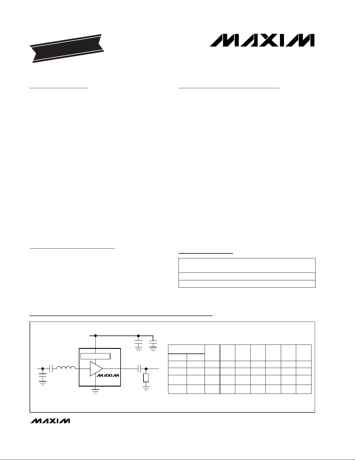
C3
C4
Z1
RFIN
C1
V
CC
V
CC
RFIN
C2
ZM1
BIAS GENERATOR
GND
LNA
RF OUT
RF OUT
MAX2640/1
ZM2
*The series inductor Z1 can be replaced by a transmission line of appropriate impedance
and electrical length.
FREQUENCY (MHz)
C1
VALUE
(pF)
C2
VALUE
(pF)
C3
VALUE
(pF)
C4
VALUE
(pF)
Z1*
VALUE
(nH)
ZM1
VALUE
(pF)
ZM2
VALUE
MAX2640 MAX2641
900
—
—
—
—
1575
1900
2450
470
100
470
470
3
100
100
100
470
470
470
470
—
—
—
100
9.85
5.6
2.55
1.65
2
1
1
1
—
6.8nH
1pF
1pF
Typical Operating Circuits
19-1384; Rev 1; 2/99
PART
MAX2640EUT-T
MAX2641EUT-T
-40°C to +85°C
-40°C to +85°C
TEMP.
RANGE
PIN-
PACKAGE
6 SOT23-6
6 SOT23-6
EVALUATION KIT
FOLLOWS DATA SHEET
Ordering Information
SOT
TOP MARK
AAAV
AAAW
Pin Configuration appears at end of data sheet.
Page 2
MAX2640/MAX2641
400MHz to 2500MHz SiGe
Ultra-Low-Noise Amplifiers
2 _______________________________________________________________________________________
ABSOLUTE MAXIMUM RATINGS
DC ELECTRICAL CHARACTERISTICS
(VCC= +2.7V to +5.5V, TA= T
MIN
to T
MAX,
unless otherwise noted. Typical values are at VCC= +3.0V, TA= +25°C.)
Stresses beyond those listed under “Absolute Maximum Ratings” may cause permanent damage to the device. These are stress ratings only, and functional
operation of the device at these or any other conditions beyond those indicated in the operational sections of the specifications is not implied. Exposure to
absolute maximum rating conditions for extended periods may affect device reliability.
VCCto GND .............................................................-0.3V to +6V
RFIN Power (50Ω source) (Note 1) ..................................+5dBm
Continuous Power Dissipation (T
A
= +70°C)
SOT23-6 (derate 8.7mW/°C above +70°C)..................696mW
Operating Temperature Range ...........................-40°C to +85°C
Maximum Junction Temperature .....................................+150°C
Storage Temperature Range.............................-65°C to +160°C
Lead Temperature (soldering, 10sec).............................+300°C
T
A
= +25°C
CONDITIONS
mA
3.5 4.7
V2.7 5.5Operating Supply Voltage
Operating Supply Current
UNITSMIN TYP MAXPARAMETER
(Note 6)
(Note 5)
(Note 4)
TA= T
MIN
to T
MAX
TA= T
MIN
to T
MAX
(Note 4)
CONDITIONS
dBm-4Input Third-Order Intercept Point
dBm-21Input 1dB Gain Compression Point
dB30Reverse Isolation
dB-12Output Return Loss
dB-12Input Return Loss
dB1.3 1.5Noise Figure
dB0.9 2.4Gain Variation Over Temperature
dB12.4 14.4Gain
MHz1400 2500RFIN Frequency Range
dB12.8 15.1Gain
MHz400 1500RFIN Frequency Range
dBm-10Input Third-Order Intercept Point
dBm-22Input 1dB Gain Compression Point
dB40Reverse Isolation
dB0.6 1.7Gain Variation Over Temperature
dB0.9 1.1Noise Figure
dB-11Input Return Loss
dB-14Output Return Loss
UNITSMIN TYP MAXPARAMETER
RF ELECTRICAL CHARACTERISTICS
(VCC= +3.0V, P
RFIN
= -34dBm, ZO= 50Ω, TA= +25°C, unless otherwise noted.) (Notes 2 and 3)
MAX2640 (f
RFIN
= 900MHz)
MAX2641 (f
RFIN
= 1900MHz)
Note 1: Pin must be AC-coupled with a DC blocking capacitor.
TA= -40°C to +85°C 6.4
Page 3
MAX2640/MAX2641
400MHz to 2500MHz SiGe
Ultra-Low-Noise Amplifiers
_______________________________________________________________________________________ 3
Note 2: Guaranteed by design and characterization.
Note 3: Measured using typical operating circuit. Input and output impedance matching networks were optimized for best simulta-
neous gain and noise-figure performance.
Note 4: External component and circuit losses degrade noise-figure performance. Specification excludes external component and
circuit board losses.
Note 5: Measured with two input tones, f
1
= 899MHz, f2= 901MHz, both at -34dBm per tone.
Note 6: Measured with two input tones, f
1
= 1899MHz, f2= 1901MHz, both at -34dBm per tone.
Note 7: Measured with two input tones, f
1
= 1574MHz, f2= 1576MHz, both at -34dBm per tone.
Note 8: Measured with two input tones, f
1
= 2449MHz, f2= 2451MHz, both at -34dBm per tone.
RF ELECTRICAL CHARACTERISTICS (continued)
(VCC= +3.0V, P
RFIN
= -34dBm, ZO= 50Ω, TA= +25°C, unless otherwise noted.) (Notes 2 and 3)
(Note 7)
(Note 4)
CONDITIONS
dBm+1.4Input Third-Order Intercept Point
dBm-21Input 1dB Gain Compression Point
dB-31Reverse Isolation
dB15.7Gain
dB1.2Noise Figure
dB-8Input Return Loss
dB-15Output Return Loss
UNITSMIN TYP MAXPARAMETER
(Note 8)
(Note 4)
dBm-2.5Input Third-Order Intercept Point
dBm-19Input 1dB Gain Compression Point
dB-24Reverse Isolation
dB13.5Gain
dB1.5Noise Figure
dB-10Input Return Loss
dB-11Output Return Loss
MAX2641 (f
RFIN
= 1575MHz)
MAX2641 (f
RFIN
= 2450MHz)
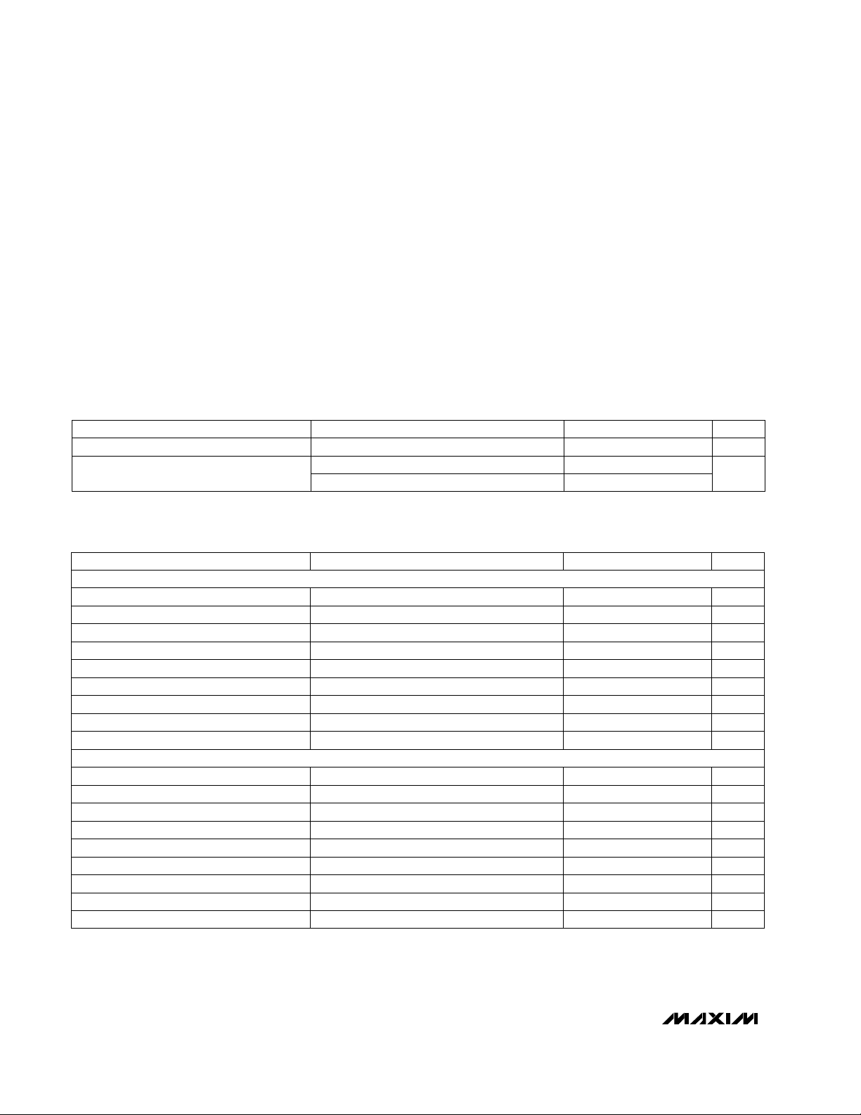
0
2
1
4
3
5
6
24356
MAX2640
SUPPLY CURRENT vs. SUPPLY VOLTAGE
MAX2640-01
VCC (V)
I
CC
(mA)
TA = +85°C
TA = +25°C
TA = -40°C
12
13
15
14
16
800 840 880 920 960 1000
MAX2640 MATCHED AT 900MHz
GAIN vs. FREQUENCY
MAX2640-01
FREQUENCY (MHz)
GAIN (dB)
TA = -40°C
TA = +25°C
TA = +85°C
0
1
2
3
800 880840 920 960 1000
MAX2640 MATCHED AT 900MHz
NOISE FIGURE vs. FREQUENCY
MAX2640-03
FREQUENCY (MHz)
NOISE FIGURE (dB)
TA = +85°C
TA = +25°C
TA = -40°C
Typical Operating Characteristics
(VCC= +3V, P
RFIN
= -34dBm, Typical Operating Circuits, TA = +25°C, unless otherwise noted.)
Page 4

MAX2640/MAX2641
400MHz to 2500MHz SiGe
Ultra-Low-Noise Amplifiers
4 _______________________________________________________________________________________
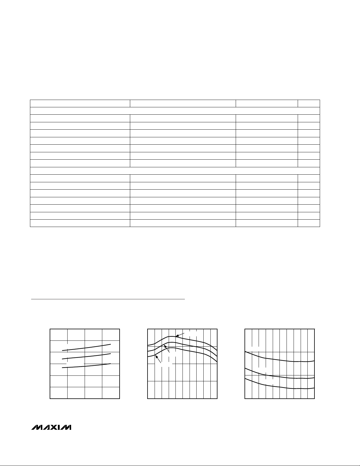
Typical Operating Characteristics (continued)
(VCC= +3V, P
RFIN
= -34dBm, Typical Operating Circuits, TA = +25°C, unless otherwise noted.)
-60
-30
-40
-50
-20
-10
0
1800 18801840 1920 1960 2000
MAX2641 MATCHED AT 1900MHz
REVERSE ISOLATION vs. FREQUENCY
MAX2640-10
FREQUENCY (MHz)
REVERSE ISOLATION (dB)
-16
-13
-14
-15
-12
-11
-10
-9
-8
-7
-6
1800 1850 1900 1950 2000
MAX2641 MATCHED AT 1900MHz
INPUT RETURN LOSS AND
OUTPUT RETURN LOSS vs. FREQUENCY
MAX2640-09
FREQUENCY (MHz)
RETURN LOSS (dB)
INPUT RETURN LOSS
OUTPUT RETURN LOSS
-16
-13
-14
-15
-12
-11
-10
-9
-8
-7
-6
800 850 900 950 1000
MAX2640 MATCHED AT 900MHz
INPUT RETURN LOSS AND
OUTPUT RETURN LOSS vs. FREQUENCY
MAX2640-04
FREQUENCY (MHz)
RETURN LOSS (dB)
INPUT RETURN LOSS
OUTPUT RETURN LOSS
12
13
15
14
16
1800 1840 1880 1920 1960 2000
MAX2641 MATCHED AT 1900MHz
GAIN vs. FREQUENCY
MAX2640-07
FREQUENCY (MHz)
GAIN (dB)
TA = -40°C
TA = +25°C
TA = +85°C
-60
-30
-40
-50
-20
-10
0
800 880840 920 960 1000
MAX2640 MATCHED AT 900MHz
REVERSE ISOLATION vs. FREQUENCY
MAX2640-05
FREQUENCY (MHz)
REVERSE ISOLATION (dB)
0
2
1
4
3
5
6
24356
MAX2641
SUPPLY CURRENT vs. SUPPLY VOLTAGE
MAX2640-06
VCC (V)
I
CC
(mA)
TA = +85°C
TA = +25°C
TA = -40°C
0
1
2
3
1800 18801840 1920 1960 2000
MAX2641 MATCHED AT 1900MHz
NOISE FIGURE vs. FREQUENCY
MAX2640-08
FREQUENCY (MHz)
NOISE FIGURE (dB)
TA = +85°C
TA = +25°C
TA = -40°C
Page 5

MAX2640/MAX2641
400MHz to 2500MHz SiGe
Ultra-Low-Noise Amplifiers
_______________________________________________________________________________________ 5
Detailed Description
The MAX2640 and MAX2641 are ultra-low-noise amplifiers that operate with RF input frequency ranges of
400MHz to 1500MHz (MAX2640) or 1400MHz to
2500MHz (MAX2641). These devices are available in
SOT23-6 packages and contain internal bias circuitry to
minimize the number of required external components.
Their small size and low external component count
make them ideal for applications where board space is
limited.
Applications Information
External Matching Components
The MAX2640/MAX2641 are easy to use, generally
requiring only five external components as shown in the
Typical Operating Circuit
. To reduce external component count further, replace external inductors with
microstrip transmission lines. The high reverse isolation
allows the tuning of the input matching network without
affecting the output match, and vice versa. Select input
and output matching networks to obtain the desired
combination of gain, noise figure, and return loss performance. The
Typical Operating Circuits
show the recommended input and output matching networks for
the MAX2640/MAX2641 at 900MHz and 1900MHz,
respectively. These values are optimized for best
simultaneous gain, noise figure, and return loss performance. To aid in the design of matching networks for
other frequencies, Tables 1 and 2 list typical device Sparameters and Tables 3 and 4 list typical device noise
parameters.
NAME FUNCTION
1 RFIN
Amplifier Input. AC-couple to this pin with a DC blocking capacitor. Use recommended input matching
network (see
Typical Operating Circuit
).
2, 3, 5 GND Ground. For optimum performance, provide a low inductance connection to the ground plane.
PIN
4 RFOUT
Amplifier Output. Use the recommended series blocking or matching capacitor (see
Typical Operating
Circuit
).
6 V
CC
Supply Voltage. Bypass to ground directly at the supply pin. The value of the bypass capacitor is determined by the lowest operating frequency. Additional bypassing may be necessary for long VCClines (see
Typical Operating Circuit
).
Pin Description
Page 6

MAX2640/MAX2641
400MHz to 2500MHz SiGe
Ultra-Low-Noise Amplifiers
6 _______________________________________________________________________________________
Table 2. MAX2641 Typical Scattering Parameters at VCC= +3V, TA= +25°C
-104.90.6881500
-98.80.7021400
-93.40.7201300
-88.00.7351200
-82.30.7491100
-76.60.7711000
-71.00.788900
-64.90.810800
-58.10.832700
-50.80.858600
-43.10.882500
-35.10.907400
PHASE
S11
MAG
FREQUENCY
(MHz)
-117.53.81
-94.94.17
-75.94.24
-53.44.48
-32.44.55
-12.04.74
9.24.77
29.54.85
50.64.80
70.74.76
90.44.70
109.14.62
PHASE
S21
MAG
-20.20.489
-9.90.482
-0.20.469
-59.80.024
10.70.455
21.90.436
33.50.412
-42.90.021
44.70.396
56.80.384
69.40.365
-28.20.015
81.50.352
93.60.33
108.40.302
-10.60.013
PHASE
S22
MAG
12.30.010
28.00.007
36.30.005
64.20.004
39.40.002
55.20.001
64.70.001
13.50.001
PHASE
S12
MAG
64.72.118
82.92.430
105.32.781
123.62.981
146.43.302
-128.40.6032500
166.93.456
-173.53.801
-150.03.876
-124.60.6042400
-131.64.193
-109.84.209
-90.54.397
-119.40.6102300
PHASE
S21
MAG
-98.30.316
-114.00.6202200
-86.20.338
-69.40.374
-108.80.6322100
-56.10.403
-43.40.431
95.70.030
-102.60.6462000 -32.00.470
-21.60.493
-10.60.510
-96.60.6611900
111.20.032
-0.50.513
8.60.514
-90.60.6781800
17.70.535
132.20.033
PHASE
S22
MAG
-85.30.6951700
150.70.029
171.70.028
-166.60.026
-80.30.7171600
-150.60.023
-128.70.021
-116.50.018
-75.50.7341500
-91.90.016
-80.30.013
PHASE
S12
MAG
PHASE
S11
MAG
FREQUENCY
(MHz)
Table 1. MAX2640 Typical Scattering Parameters at VCC= +3V, TA= +25°C
Page 7

MAX2640/MAX2641
400MHz to 2500MHz SiGe
Ultra-Low-Noise Amplifiers
_______________________________________________________________________________________ 7
Layout and Power-Supply Bypassing
A properly designed PC board is essential to any
RF/microwave circuit. Be sure to use controlled impedance lines on all high-frequency inputs and outputs.
The power supply should be bypassed with decoupling
capacitors located close to the device VCCpins. For
long VCClines, it may be necessary to add additional
decoupling capacitors. These additional capacitors
can be located further away from the device package.
Proper grounding of the GND pins is essential. If the
PC board uses a topside RF ground, connect it directly
to all GND pins. For a board where the ground plane is
not on the component side, the best technique is to
connect the GND pin to the board with a plated
through-hole close to the package.
FREQUENCY (MHz) f
MIN
(dB)
Γ
opt
Γ
opt
ANGLE
RN(Ω)
1500 1.02 0.43 44 12.4
1600 1.05 0.40 47 11.8
1700 1.08 0.38 50 11.3
1800 1.10 0.36 54 10.8
1900 1.14 0.32 58 10.3
2000 1.17 0.30 62 9.9
2100 1.20 0.28 66 9.4
2200 1.23 0.25 71 9.0
2300 1.27 0.22 77 8.6
2400 1.30 0.19 82 8.3
2500 1.34 0.17 91 8.0
Table 3. MAX2640 Typical Noise Parameters at VCC= +3V, TA= +25°C
Table 4. MAX2641 Typical Noise Parameters at VCC= +3V, TA= +25°C
7.0840.261.061500
7.4770.291.011400
7.9680.320.971300
8.3620.350.931200
8.8560.370.891100
9.3500.400.851000
9.7450.430.82900
10.2400.460.78800
10.8350.480.75700
11.3300.510.72600
11.9250.540.69500
12.5210.560.66400
RN(Ω)
Γ
opt
ANGLE
Γ
opt
f
MIN
(dB)FREQUENCY (MHz)
Page 8

MAX2640/MAX2641
400MHz to 2500MHz SiGe
Ultra-Low-Noise Amplifiers
8 _______________________________________________________________________________________
GND
RFOUTGND
16V
CC
5 GND
RFIN
MAX2640
MAX2641
SOT23-6
TOP VIEW
2
34
Pin Configuration
Package Information
6LSOT.EPS
 Loading...