

Page 1
General Description
The MAX2036 8-channel variable-gain amplifier (VGA)
and programmable octal mixer array is designed for
high linearity, high dynamic range, and low-noise performance targeting ultrasound imaging and Doppler
applications. Each amplifier features differential inputs
and outputs and a total gain range of 50dB (typ). In
addition, the VGAs offer very low output-referred noise
performance suitable for interfacing with 10-bit ADCs.
The MAX2036 VGA is optimized for less than ±0.5dB
absolute gain error to ensure minimal channel-to-channel
ultrasound beamforming focus error. The device’s differential outputs are designed to directly drive ultrasound
ADCs through an external passive anti-aliasing filter. A
switchable clamp is also provided at each amplifier’s
output to limit the output signals, thereby preventing
ADC overdrive or saturation.
Dynamic performance of the device is optimized to
reduce distortion to support second-harmonic imaging.
The device achieves a second-harmonic distortion
specification of -62dBc at V
OUT
= 1.5V
P-P
and fIN=
5MHz, and an ultrasound-specific* two-tone third-order
intermodulation distortion specification of -52dBc at
V
OUT
= 1.5V
P-P
and fIN= 5MHz.
The MAX2036 also integrates an octal quadrature mixer
array and programmable LO phase generators for a
complete CW beamforming solution. The LO phase
selection for each channel can be programmed using a
digital serial interface and a single high-frequency
clock or the LOs for each complex mixer pair can be
directly driven using separate 4 x LO clocks. The serial
interface is designed to allow multiple devices to be
easily daisy-chained in order to minimize program interface wiring. The LO phase dividers can be programmed to allow 4, 8, or 16 quadrature phases. The
input path of each CW mixer consists of a selectable
lowpass filter for optimal CWD noise performance. The
outputs of the mixers are summed into I and Q differential current outputs. The mixers and LO generators are
designed to have exceptionally low noise performance
of -155dBc/Hz at 1kHz offset from a 1.25MHz carrier.
The MAX2036 operates from a +5.0V power supply,
consuming only 120mW/channel in VGA mode and
269mW/channel in normal power CW mode. A lowpower CW mode is also available and consumes only
226mW/channel. The device is available in a lead-free
100-pin TQFP package (14mm x 14mm) with an
exposed pad. Electrical performance is guaranteed
over a 0°C to +70°C temperature range.
Applications
Ultrasound Imaging Sonar
Features
♦ 8-Channel Configuration
♦ High Integration for Ultrasound Imaging
Applications
♦ Pin Compatible with the MAX2035 Ultrasound
VGA
VGA Features
♦ Maximum Gain, Gain Range, and Output-Referred
Noise Optimized for Interfacing with 10-Bit ADCs
Maximum Gain of 39.5dB
Total Gain Range of 50dB
-60nV/√√Hz Ultra-Low Output-Referred Noise at
5MHz
♦ ±0.5dB Absolute Gain Error
♦ 120mW Consumption per Channel
♦ Switchable Output VGA Clamp Eliminating ADC
Overdrive
♦ Fully Differential VGA Outputs for Direct ADC
Drive
♦ Variable Gain Range Achieves 50dB Dynamic
Range
♦ -62dBc HD2 at V
OUT
= 1.5V
P-P
and fIN= 5MHz
♦ Two-Tone Ultrasound-Specific* IMD3 of -52dBc at
V
OUT
= 1.5V
P-P
and fIN= 5MHz
CWD Mixer Features
♦ Low Mixer Noise of -155dBc/Hz at 1kHz Offset
from 1.25MHz Carrier
♦ Serial-Programmable LO Phase Generator for 4, 8,
16 LO Quadrature Phase Resolution
♦ Optional Individual Channel 4 x fLOLO Input
Drive Capability
♦ 269mW Power Consumption per Channel (Normal
Power Mode) and 226mW Power Consumption
per Channel (Low-Power Mode)
♦ CWD Implementation Is Fully Compliant with All
Patents Related to Ultrasound Imaging
Techniques
MAX2036
Ultrasound VGA Integrated
with CW Octal Mixer
________________________________________________________________
Maxim Integrated Products
1
Ordering Information
19-4420; Rev 0; 1/09
For pricing, delivery, and ordering information, please contact Maxim Direct at 1-888-629-4642,
or visit Maxim’s website at www.maxim-ic.com.
+
Denotes a lead(Pb)-free/RoHS-compliant package.
T = Tape-and-reel package.
D = Dry packing.
†
EP = Exposed pad.
PART TEMP RANGE PIN-PACKAGE
MAX2036CCQ+D 0°C to +70°C 100 TQFP-EP
†
MAX2036CCQ+TD 0°C to +70°C 100 TQFP-EP
†
Pin Configuration appears at end of data sheet.
*
See the Ultrasound-Specific IMD3 Specification in the
Applications Information section.
Page 2
MAX2036
Ultrasound VGA Integrated
with CW Octal Mixer
2 _______________________________________________________________________________________
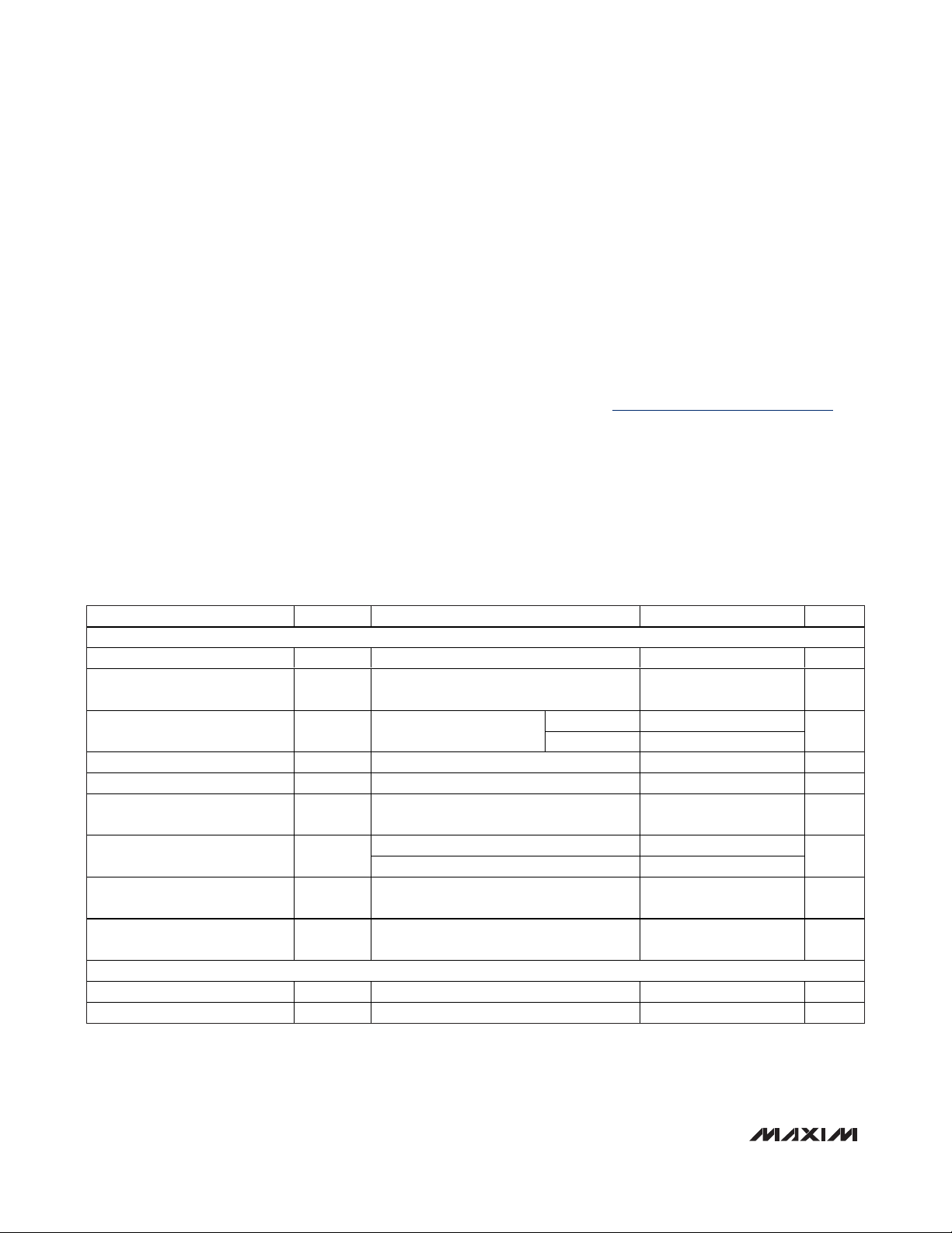
ABSOLUTE MAXIMUM RATINGS
DC ELECTRICAL CHARACTERISTICS—VGA MODE
(Figure 7, V
CC
= V
REF =
4.75V to 5.25V, VCM= (3/5)V
REF
, T
A =
0°C to +70°C, V
GND
= 0, LOW_PWR = 0, M4_EN = 0, CW_FILTER = 0
or 1, TMODE = 0, PD = 0, CW_VG = 1, CW_M1 = 0, CW_M2 = 0, no RF signals applied, capacitance to GND at each of the VGA
differential outputs is 60pF, differential capacitance across the VGA outputs is 10pF, R
L =
1kΩ, CW mixer outputs pulled up to +11V
through four separate ±0.1% 115Ω resistors, all CW channels programmed off. Typical values are at V
CC
= V
REF
=5V, TA= +25°C,
unless otherwise noted.) (Note 2)
Stresses beyond those listed under “Absolute Maximum Ratings” may cause permanent damage to the device. These are stress ratings only, and functional
operation of the device at these or any other conditions beyond those indicated in the operational sections of the specifications is not implied. Exposure to
absolute maximum rating conditions for extended periods may affect device reliability.
VCC, V
REF
to GND .................................................-0.3V to +5.5V
Any Other Pins to GND...............................-0.3V to (V
CC
+ 0.3V)
CW Mixer Output Voltage to GND (CW_IOUT+, CW_IOUT-,
CW_QOUT+, CW_QOUT-) ................................................13V
VGA Differential Input Voltage (VGIN_+, VGIN_-)............8.0V
P-P
Analog Gain Control Differential Input Voltage
(VG_CTL+, VG_CTL-) ..................................................8.0V
P-P
CW Mixer Differential Input Voltage
(CWIN_+, CWIN_-).......................................................8.0V
P-P
CW Mixer LVDS LO Differential Input Voltage..................8.0V
P-P
Continuous Power Dissipation (TA= +70°C)
100-Pin TQFP (derated 45.5mW/°C above +70°C)..3636.4mW
Operating Temperature Range...............................0°C to +70°C
Junction Temperature......................................................+150°C
θ
JC
(Note 1) .....................................................................+2°C/W
θ
JA
(Note 1)....................................................................+22°C/W
Storage Temperature Range .............................-40°C to +150°C
Lead Temperature (soldering, 10s) .................................+300°C
PARAMETER
CONDITIONS
VGA MODE
Supply Voltage Range V
CC
5
V
VCC External Reference Voltage
Range
V
REF
(Note 3)
5
V
PD = 0
231
Total Power-Supply Current
Refers to V
CC
supply
current plus V
REF
current
PD =1 27 33
mA
VCC Supply Current I
VCC
216 mA
V
REF
Current I
REF
12 15 mA
Current Consumption per
Amplifier Channel
Refers to V
CC
supply current 24 27 mA
Minimum gain +2
Differential Analog Control
Voltage Range
Maximum gain -2
V
P-P
Differential Analog Control
Common-Mode Voltage
V
CM
3
V
Analog Control Input Source/Sink
Current
4.5 5 mA
LOGIC INPUTS
CMOS Input High Voltage V
IH
2.3 V
CMOS Input Low Voltage V
IL
0.8 V
Note 1: Package thermal resistances were obtained using the method described in JEDEC specification JESD51-7, using a four-
layer board. For detailed information on package thermal considerations, refer to www.maxim-ic.com/thermal-tutorial
.
SYMBOL
MIN TYP MAX UNITS
4.75
4.75
204
192
2.85
5.25
5.25
3.15
Page 3
MAX2036
Ultrasound VGA Integrated
with CW Octal Mixer
_______________________________________________________________________________________ 3
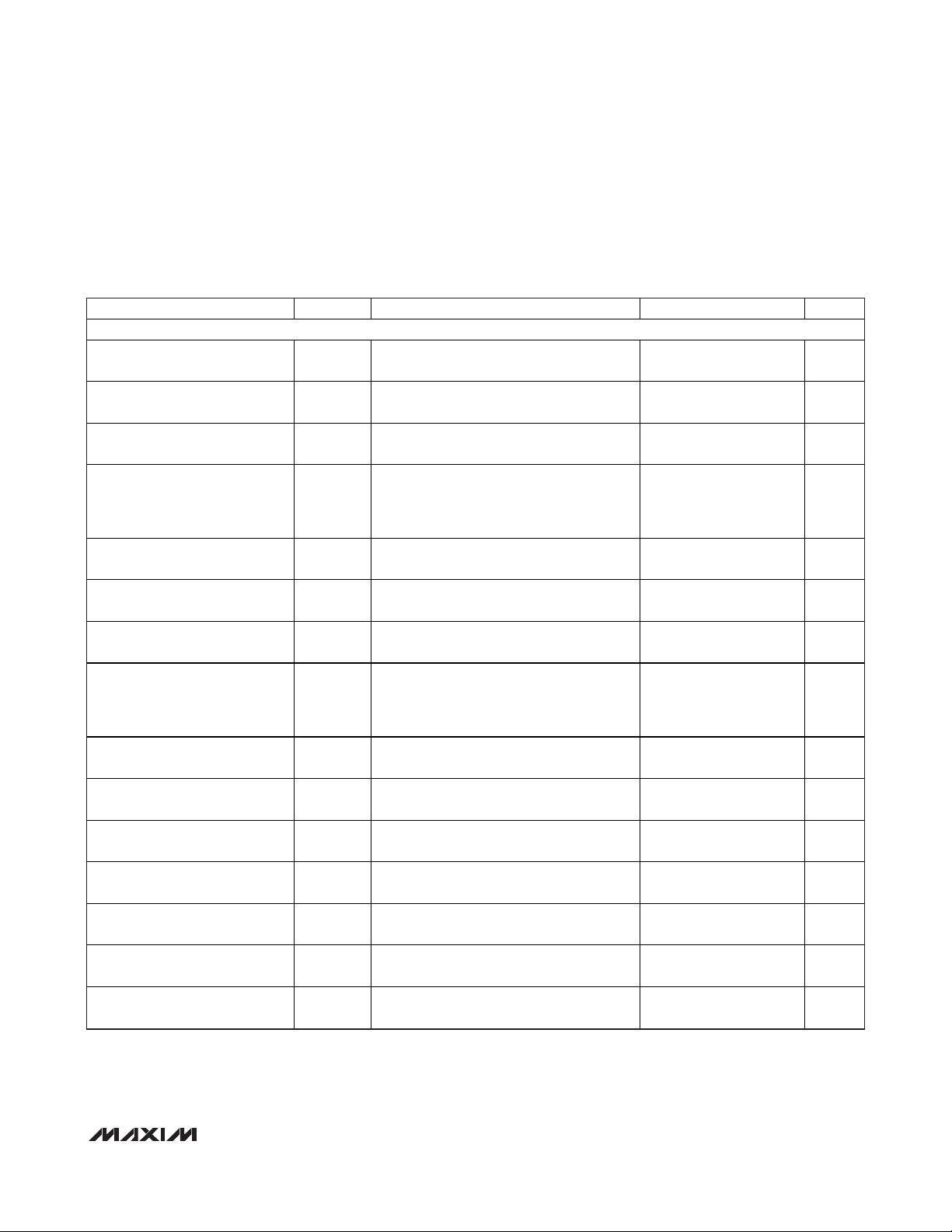
DC ELECTRICAL CHARACTERISTICS—CM MIXER MODE
(Figure 7, V
CC
= V
REF =
4.75V to 5.25V, T
A =
0°C to +70°C, V
GND
= 0, LOW_PWR = 0, M4_EN = 0, CW_FILTER = 0 or 1, TMODE = 0,
PD = 0, CW_VG = 0, CW_M1 = 0, CW_M2 = 0, no RF signals applied, capacitance to GND at each of the VGA differential outputs is
60pF, differential capacitance across the VGA outputs is 10pF, R
L =
1kΩ, CW mixer outputs pulled up to +11V through four separate
±0.1% 115Ω resistors. Typical values are at V
CC
= V
REF
=5V, TA= +25°C, unless otherwise noted.) (Note 2)
PARAMETER
CONDITIONS
CW MIXER MODE
Current in Full-Power Mode
5V V
CC
Supply
I
CC_FP
265 mA
Current in Full-Power Mode
11V V
MIX
Supply
I
MIX_FP
120 mA
Current in Full-Power Mode
5V V
REF
Supply
I
REF_FP
17 21 mA
Power Dissipation in Full-Power
Mode
Total power dissipation (all 8 channels
including both 5V (V
CC
and V
REF
) and 11V
mixer pullup supply power dissipation in the
device) (Note 4)
W
Current in Low-Power Mode
5V V
CC
Supply
I
CC_LP
LOW_PWR = 1; refers to VCC supply
current (all 8 channels)
265 mA
Current in Low-Power Mode
11V V
MIX
Supply
I
MIX_LP
LOW_PWR = 1; refers to V
MIX
supply
current (all 8 channels)
53 60 mA
Current in Low-Power Mode
5V V
REF
Supply
I
REF_LP
LOW_PWR = 1; refers to V
REF
supply
current (all 8 channels)
17 21 mA
Power Dissipation in Low-Power
Mode
LOW_PWR = 1; total power dissipation (all 8
channels including both 5V (V
CC
and V
REF
)
and 11V mixer pullup supply power
dissipation in the device) (Note 4)
W
Mixer LVDS LO Input CommonMode Voltage
Modes 1 and 2 (Note 5)
V
LVDS LO Differential Input
Voltage
Modes 1 and 2
LVDS LO Input Common-Mode
Current
Per pin
200 µA
LVDS LO Differential Input
Resistance
Modes 1 and 2 (Note 6) 30 kΩ
Mixer IF Common-Mode Output
Current
Common-mode current in each of the
differential mixer outputs (Note 7)
mA
DATA Output High Voltage
DOUT voltage when terminated in DIN
(daisy chain) (Note 8)
4.5 V
DATA Output Low Voltage
DOUT voltage when terminated in DIN
(daisy chain) (Note 8)
0.5 V
SYMBOL
P
DISS_FP
P
DISS_LP
Refer s to V
Refer s to V
Refer s to V
sup p l y cur r ent ( al l 8 channel s) 245
C C
sup p l y cur r ent ( al l 8 channel s) 106
M IX
sup p l y cur r ent ( al l 8 channel s)
R E F
MIN TYP MAX UNITS
2.15 2.41
245
1.81 2.06
1.25
±0.2
200 700 mV
150
3.25 3.75
P-P
Page 4
MAX2036
Ultrasound VGA Integrated
with CW Octal Mixer
4 _______________________________________________________________________________________
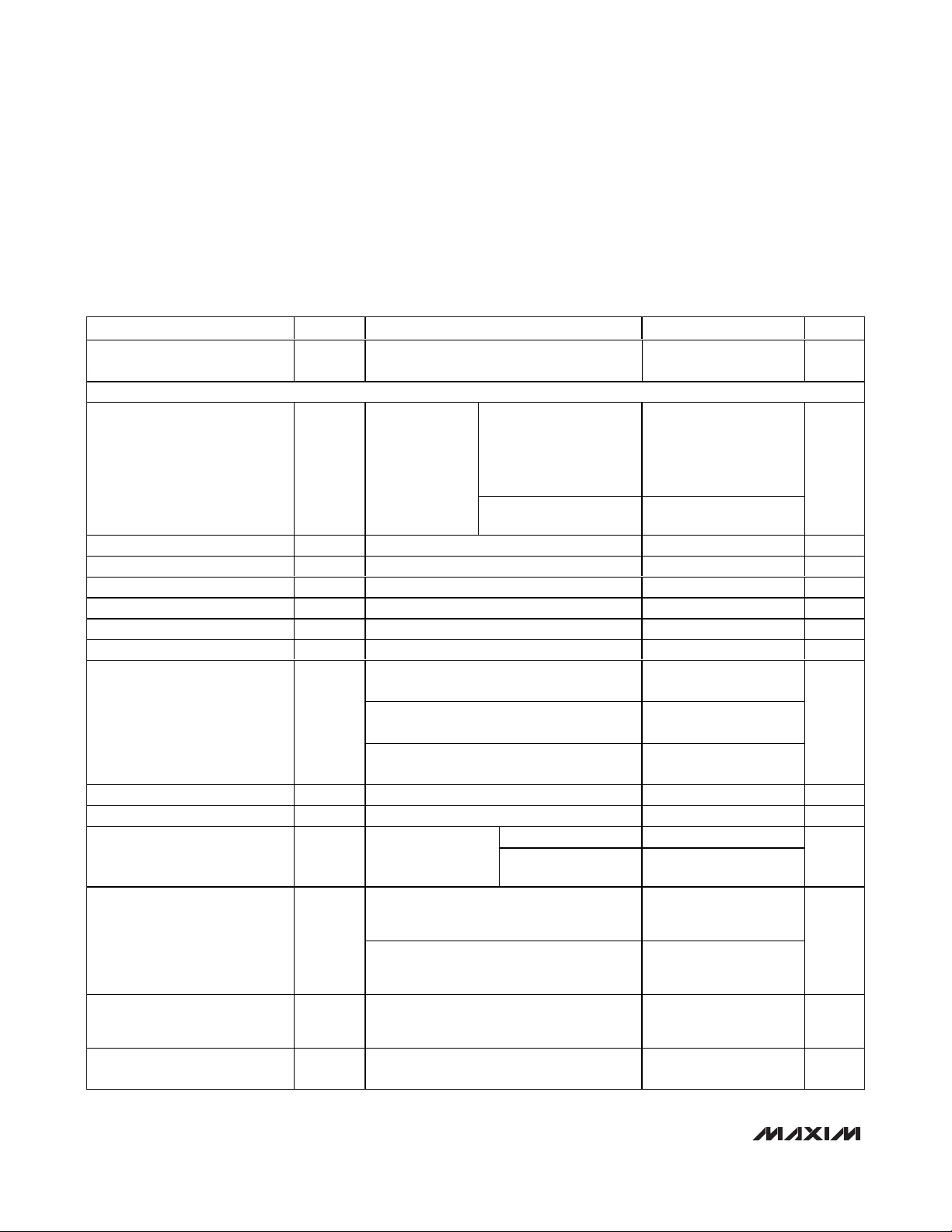
AC ELECTRICAL CHARACTERISTICS—VGA MODE
(Figure 7, VCC= V
REF
= 4.75V to 5.25V, VCM= (3/5)V
REF
, TA= 0°C to +70°C, V
GND
= 0, LOW_PWR = 0, M4_EN = 0, CW_FILTER = 1,
TMODE = 0, PD = 0, CW_VG = 1, CW_M1 = 0, CW_M2 = 0, VG_CLAMP_MODE = 1, f
RF
= fLO/16 = 5MHz, capacitance to GND at
each of the VGA differential outputs is 60pF, differential capacitance across the VGA outputs is 10pF, R
L
= 1kΩ, CW mixer outputs
pulled up to +11V through four separate ±0.1% 115Ω resistors, differential mixer inputs are driven from a low-impedance source.
Typical values are at V
CC
= V
REF
= 5V, TA= +25°C, unless otherwise noted.) (Note 2)
PARAMETER
CONDITIONS
UNITS
Mode Select Response Time
CW_VG set from logic 1 to 0 or from 0 to 1
(Note 9)
2µs
VGA MODE
Differential output
capacitance is 10pF,
capacitance to GND at
each single-ended output
is 60pF, R
L
= 1kΩ
17
Large-Signal Bandwidth f
-3dB
gain = 20dB
No capacitive load,
RL = 1kΩ
22
MHz
Differential Input Resistance R
IN
Ω
Input Effective Capacitance C
IN
fRF = 10MHz, each input to ground 15 pF
Differential Output Resistance R
OUT
Ω
Maximum Gain
dB
Minimum Gain
dB
Gain Range 50 dB
TA = +25°C, -2.0V < VG_CTL < -1.8V,
V
REF
= 5V
TA = +25°C, -1.8V < VG_CTL < +1.2V,
V
REF
= 5V
Absolute Gain Error
T
A
= +25°C, +1.2V < VG_CTL < +2.0V,
V
REF
= 5V
dB
VGA Gain Response Time 50dB gain change to within 1dB final value 1 µs
Input-Referred Noise V G_C TL set for m axi m um g ai n, no i np ut si g nal 2
nV/√Hz
No input signal 60
Output-Referred Noise
VG_CTL set for
+20dB of gain
V
OUT
= 1.5V
P-P
,
1kHz offset
nV/√Hz
VG_CLAMP_MODE = 1,
VG_CTL set for +20dB of gain,
f
RF
= 5MHz, V
OUT
= 1.5V
P-P
-55 -62
Second Harmonic HD2
VG_CLAMP_MODE = 1,
VG_CTL set for +20dB of gain,
f
RF
= 10MHz, V
OUT
= 1.5V
P-P
-62
dBc
Third-Order Intermodulation
Distortion
IMD3
VG_CTL set for +20dB of gain,
f
RF1
= 5MHz, f
RF2
= 5.01MHz,
V
OUT
= 1.5V
P-P
, V
REF
= 5V (Note 3)
-40 -52 dBc
Channel-to-Channel Crosstalk
V
OUT
= 1V
P-P
differential, fRF = 10MHz,
VG_CTL set for +20dB of gain
-80 dB
SYMBOL
MIN TYP MAX
V
= 1.5V
OUT
3dB bandwidth,
,
P-P
170 200 230
100
39.5
-10.5
±0.6
±0.5
±1.2
120
Page 5
MAX2036
Ultrasound VGA Integrated
with CW Octal Mixer
_______________________________________________________________________________________ 5
AC ELECTRICAL CHARACTERISTICS—CW MIXER MODE (continued)
(Figure 7, VCC= V
REF
= 4.75V to 5.25V, TA= 0°C to +70°C, V
GND
= 0, LOW_PWR = 0, M4_EN = 0, CW_FILTER = 1, TMODE = 0,
PD = 0, CW_VG = 0, CW_M1 = 0, CW_M2 = 0, VG_CLAMP_MODE = 1, f
RF
= fLO/16 = 5MHz, capacitance to GND at each of the
VGA differential outputs is 60pF, differential capacitance across the VGA outputs is 10pF, R
L
= 1kΩ, CW mixer outputs pulled up to
+11V through four separate ±0.1% 115Ω resistors, differential mixer inputs are driven from a low-impedance source. Typical values
are at V
CC
= V
REF
= 5V, TA= +25°C, unless otherwise noted.) (Note 2)
PARAMETER
CONDITIONS
Maximum Output Voltage at
Clamp ON
VG_CLAMP_MODE = 0,
VG_CTL set for +20dB of gain,
350mV
P-P
differential input
2.2
V
P-P
Maximum Output Voltage at
Clamp OFF
VG_CLAMP_MODE = 1,
VG_CTL set for +20dB of gain,
350mV
P-P
differential input
3.4
V
P-P
CW MIXER MODE
Mixer RF Frequency Range 0.9 7.6 MHz
Mixer LO Frequency Range 1 7.5 MHz
Mixer IF Frequency Range
kHz
Maximum Input Voltage Range 1.8
V
P-P
CW_FILTER = 0
Differential Input Resistance
CW_FILTER = 1
Ω
M od e 3, fRF = fLO/4 = 1.25M H z, m easur ed at a
1kH z offset fr eq uency; cl utter tone at 0.9V
P - P
d i ffer enti al m easur ed at the m i xer i np ut
6
Input-Referred Noise Voltage
Mode 3, RF terminated into 50Ω;
f
LO
/4 = 1.25MHz, measured at 1kHz offset
4.6
Third-Order Intermodulation
Distortion
IMD3
Mode 1, f
RF1
= 5MHz at 0.9V
P-P
differential
input, Doppler tone f
RF2
= 5.01MHz at 25dBc
from clutter tone, f
LO
/16 = 5MHz (Note 10)
-50 dBc
M i xer O utp ut V ol tag e C om p l i ance
(Note 11)
V
Channel-to-Channel Phase
Matching
Measured under zero beat conditions,
f
RF
= 5MHz, fLO/16 = 5MHz (Note 12)
±3
Channel-to-Channel Gain
Matching
Measured under zero beat conditions,
f
RF
= 5MHz, fLO/16 = 5MHz (Note 12)
±2 dB
CW_FILTER = 1
f
RF
= 1.1MHz at 1V
P - P
d i ffer enti al ,
f
LO
/16 = 1MHz
2.8
Transconductance
(Note 13)
CW_FILTER = 0
(low LPF cutoff
frequency)
f
RF
= 1.1MHz at 1V
P - P
d i ffer enti al ,
f
LO
/16 = 1MHz
2.8
mS
SYMBOL
MIN TYP MAX UNITS
4.75 12.00
633
1440
d i ffer enti al
d i ffer enti al
100
d i ffer enti al
nV/√Hz
Degrees
Page 6
MAX2036
Ultrasound VGA Integrated
with CW Octal Mixer
6 _______________________________________________________________________________________
AC ELECTRICAL CHARACTERISTICS—CW MIXER MODE (continued)
(Figure 7, VCC= V
REF
= 4.75V to 5.25V, TA= 0°C to +70°C, V
GND
= 0, LOW_PWR = 0, M4_EN = 0, CW_FILTER = 1, TMODE = 0,
PD = 0, CW_VG = 0, CW_M1 = 0, CW_M2 = 0, VG_CLAMP_MODE = 1, f
RF
= fLO/16 = 5MHz, capacitance to GND at each of the VGA
differential outputs is 60pF, differential capacitance across the VGA outputs is 10pF, R
L
= 1kΩ, CW mixer outputs pulled up to +11V
through four separate ±0.1% 115Ω resistors, differential mixer inputs are driven from a low-impedance source. Typical values are at
V
CC
= V
REF
= 5V, TA= +25°C, unless otherwise noted.) (Note 2)
PARAMETER
CONDITIONS
UNITS
SERIAL SHIFT REGISTER
Serial Shift Register Programming
Rate
10 MHz
Minimum Data Set-Up Time t
DSU
30 ns
Minimum Data Hold Time t
HLD
2ns
Minimum Data Clock Time t
DCLK
ns
Minimum Data Clock Pulse Width
High
30 ns
Minimum Data Clock Pulse Width
Low
30 ns
Minimum Load Line t
LD
30 ns
Minimum Load Line High to Mixer
Clock On
30 ns
Minimum Data Clock to Load
Line High
t
CLH
30 ns
Note 2: Specifications at TA= +25°C and TA= +70°C are guaranteed by production. Specifications at TA= 0°C are guaranteed by
design and characterization.
Note 3: Noise performance of the device is dependent on the noise contribution from the supply to V
REF
. Use a low-noise supply
for V
REF
. VCCand V
REF
can be connected together to share the same supply voltage if the supply for VCCexhibits low
noise.
Note 4: Total on-chip power dissipation is calculated as P
DISS
= VCCx ICC+ V
REF
x I
REF
+ [11V - (I
MIX
/4) x 115] x I
MIX
.
Note 5: Note that the LVDS CWD LO clocks are DC-coupled. This is to ensure immediate synchronization when the clock is first
turned on. An AC-coupled LO is problematic in that the RC time constant associated with the coupling capacitors and the
input impedance of the pin causes there to be a period of time (related to the RC time constant) when the DC level on the
chip side of the capacitor is outside the acceptable common-mode range and the LO swing does not exceed both the
logic thresholds required for proper operation. This problem associated with AC-coupling would cause an inability to
ensure synchronization among beamforming channels. The LVDS signal is terminated differentially with an external 100Ω
resistor on the board.
Note 6: External 100Ω resistor terminates the LVDS differential signal path.
Note 7: The mixer common-mode current (3.25mA/channel) is specified as the common-mode current in each of the differential
mixer outputs (CW_QOUT+, CW_QOUT-, CW_IOUT+, CW_IOUT-).
Note 8: Specification guaranteed only for DOUT driving DIN of the next device in a daisy-chain fashion.
Note 9: This response time does not include the CW output highpass filter. When switching to VGA mode, the CW outputs stop
drawing current and the output voltage goes to the rail. If a highpass filter is used, the recovery time can be excessive and
a switching network is recommended as shown in the
Applications Information
section.
Note 10: See the
Ultrasound-Specific IMD3 Specification
in the
Applications Information
section.
Note 11: Mixer output-voltage compliance is the range of acceptable voltages allowed on the CW mixer outputs.
Note 12: Channel-to-channel gain-and-phase matching measured on 30 pieces during engineering characterization at room temper-
ature. Each mixer is used as a phase detector and produces a DC voltage in the IQ plane. The phase is given by the angle
of the vector drawn on that plane. Multiple channels from multiple parts are compared to each other to produce the phase
variation.
Note 13: Transconductance is defined as the quadrature summing of the CW differential output current at baseband divided by the
mixer’s input voltage.
SYMBOL
MIN TYP MAX
100
t
DCLKPWH
t
DCLKPWL
t
MIXCLK
Page 7
MAX2036
Ultrasound VGA Integrated
with CW Octal Mixer
_______________________________________________________________________________________ 7
Typical Operating Characteristics
(Figure 7, VCC= V
REF
= 4.75V to 5.25V, V
GND
= 0, PD = 0, VG_CLAMP_MODE = 1, fRF= 5MHz, capacitance to GND at each of the
VGA differential outputs is 60pF, differential capacitance across the VGA outputs is 10pF, R
L
= 1kΩ, TA= 0°C to +70°C. Typical val-
ues are at V
CC
= V
REF
= 5V, VCM= 3.0V, TA= +25°C, unless otherwise noted.)
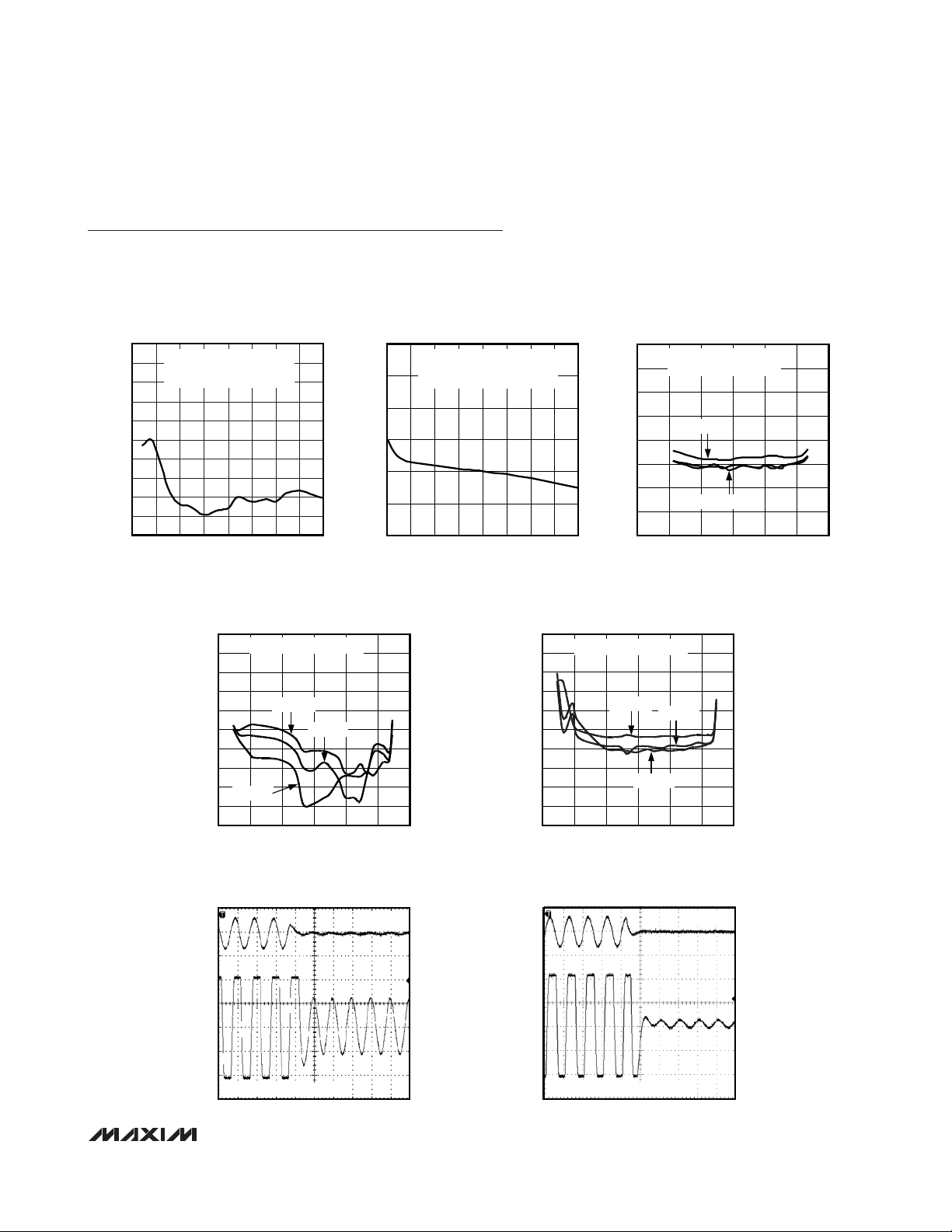
OVERDRIVE PHASE DELAY
vs. FREQUENCY
MAX2036 toc01
V
IN1
= 35mV
P-P
DIFFERENTIAL
V
IN2
= 87.5mV
P-P
DIFFERENTIAL
GAIN = 20dB
5.0
4.5
4.0
3.5
3.0
2.5
2.0
1.5
1.0
0.5
0
0 2.5 5.0 7.5 10.0 12.5 15.0
OVERDRIVE PHASE DELAY (ns)
FREQUENCY (MHz)
17.5 20.0
POWER-SUPPLY MODULATION RATIO
MAX2036 toc02
V
OUT
= 1.5V
P-P
DIFFERENTIAL
V
MOD
= 50mV
P-P
, f
CARRIER
= 5MHz,
GAIN = 20dB
-30
-40
-50
-60
-70
-80
-90
0 25 50 75 100 125 150
PSMR (dBc)
FREQUENCY (kHz)
175 200
TWO-TONE ULTRASOUND-SPECIFIC
IMD3 vs. GAIN
MAX2036 toc03
-30
-40
-50
-60
-70
-80
-20
-10
0
-15 -5 5 15 25 35 45
IMD3 (dBc)
GAIN (dB)
V
OUT
= 1V
P-P
DIFFERENTIAL
GAIN = 20dB
f = 2MHz, 5MHz
f = 10MHz
OVERLOAD RECOVERY TIME
MAX2036 toc07
OUTPUT OVERLOAD TO 100mV
P-P
f = 5MHz
DIFFERENTIAL
INPUT
200mV/div
DIFFERENTIAL
OUTPUT
500mV/div
SECOND-HARMONIC DISTORTION
vs. GAIN
MAX2036 toc04
-30
-40
-50
-60
-70
-100
-90
-80
-20
-10
0
-15 -5 5 15 25 35 45
HD2 (dBc)
GAIN (dB)
f = 2MHz
V
OUT
= 1V
P-P
DIFFERENTIAL
f = 5MHz
f = 12MHz
THIRD-HARMONIC DISTORTION
vs. GAIN
MAX2036 toc05
-30
-40
-50
-60
-70
-100
-90
-80
-20
-10
0
-15 -5 5 15 25 35 45
HD3 (dBc)
GAIN (dB)
V
OUT
= 1V
P-P
DIFFERENTIAL
f = 12MHz
f = 5MHz
f = 2MHz
OVERLOAD RECOVERY TIME
MAX2036 toc06
OUTPUT OVERLOAD TO 1V
P-P
f = 5MHz
DIFFERENTIAL
INPUT
200mV/div
DIFFERENTIAL
OUTPUT
500mV/div
Page 8

MAX2036
Ultrasound VGA Integrated
with CW Octal Mixer
8 _______________________________________________________________________________________
LARGE-SIGNAL BANDWIDTH
vs. FREQUENCY
MAX2036 toc14
30
25
20
15
10
5
0
-5
-10
0.1 10 1001 1000
FREQUENCY (MHz)
GAIN (dB)
V
OUT
= 1.5V
P-P
DIFFERENTIAL
VG_CTL = +0.2V
P-P
DIFFERENTIAL
LARGE-SIGNAL BANDWIDTH
vs. FREQUENCY
MAX2036 toc15
20
15
10
5
0
-5
-10
-15
-20
0.1 10 1001 1000
GAIN (dB)
V
OUT
= 1.5V
P-P
DIFFERENTIAL
VG_CTL = +1.2V
P-P
DIFFERENTIAL
FREQUENCY (MHz)
LARGE-SIGNAL BANDWIDTH
vs. FREQUENCY
MAX2036 toc16
10
5
0
-5
-10
-15
-20
-25
-30
0.1 10 1001 1000
GAIN (dB)
V
OUT
= 1.5V
P-P
DIFFERENTIAL
VG_CTL = +1.7V
P-P
DIFFERENTIAL
FREQUENCY (MHz)
GAIN vs. DIFFERENTIAL ANALOG
CONTROL VOLTAGE (VG_CTL)
MAX2036 toc11
-15
5
-5
25
15
35
45
-2.5 2.5
VG_CTL (V
P-P
DIFFERENTIAL)
GAIN (dB)
-0.5-1.5 0.5 1.5
f = 5MHz
50
45
40
35
30
25
20
15
10
0.1 10 1001 1000
FREQUENCY (MHz)
GAIN (dB)
LARGE-SIGNAL BANDWIDTH
vs. FREQUENCY
MAX2036 toc12
V
OUT
= 1.5V
P-P
DIFFERENTIAL
VG_CTL = -2V
P-P
DIFFERENTIAL
LARGE-SIGNAL BANDWIDTH
vs. FREQUENCY
MAX2036 toc13
40
35
30
25
20
15
10
5
0
0.1 10 1001 1000
FREQUENCY (MHz)
GAIN (dB)
V
OUT
= 1.5V
P-P
DIFFERENTIAL
VG_CTL = -0.8V
P-P
DIFFERENTIAL
CHANNEL-TO-CHANNEL CROSSTALK
vs. GAIN
MAX2036 toc08
-65
-70
-75
-80
-85
-100
-95
-90
-60
-15 -5 5 15 25 35 45
CROSSTALK (dB)
GAIN (dB)
V
OUT
= 1.5V
P-P
DIFFERENTIAL
f = 10MHz, ADJACENT CHANNELS
-30
-110
1 10 100
CHANNEL-TO-CHANNEL CROSSTALK
vs. FREQUENCY
-90
-100
MAX2036 toc09
FREQUENCY (MHz)
CROSSTALK (dB)
-70
-80
-60
-50
-40
V
OUT
= 1V
P-P
DIFFERENTIAL
GAIN = 20dB, ADJACENT CHANNELS
OUTPUT-REFERRED NOISE VOLTAGE
vs. GAIN
MAX2036 toc10
80
70
60
50
40
30
-15 -5 5 15 25 35 45
OUTPUT-REFERRED NOISE VOLTAGE (nV/√Hz)
GAIN (dB)
f = 5MHz
Typical Operating Characteristics (continued)
(Figure 7, VCC= V
REF
= 4.75V to 5.25V, V
GND
= 0, PD = 0, VG_CLAMP_MODE = 1, fRF= 5MHz, capacitance to GND at each of the
VGA differential outputs is 60pF, differential capacitance across the VGA outputs is 10pF, R
L
= 1kΩ, TA= 0°C to +70°C. Typical val-
ues are at V
CC
= V
REF
= 5V, VCM= 3.0V, TA= +25°C, unless otherwise noted.)
Page 9

MAX2036
Ultrasound VGA Integrated
with CW Octal Mixer
_______________________________________________________________________________________ 9
LARGE-SIGNAL BANDWIDTH
vs. FREQUENCY
MAX2036 toc17
0
-5
-10
-15
-20
-25
-30
-35
-40
0.1 10 1001 1000
GAIN (dB)
V
OUT
= 1V
P-P
DIFFERENTIAL
VG_CTL = +2V
P-P
DIFFERENTIAL
FREQUENCY (MHz)
HARMONIC DISTORTION
vs. DIFFERENTIAL OUTPUT VOLTAGE
MAX2036 toc18
-100
-70
-80
-90
-60
-50
-40
-30
-20
-10
0
01.00.5 1.5 2.0 2.5 3.0
DIFFERENTIAL OUTPUT VOLTAGE (V
P-P
)
HARMONIC DISTORTION (dBc)
f = 5MHz, GAIN = 20dB
THIRD HARMONIC
SECOND HARMONIC
HARMONIC DISTORTION
vs. DIFFERENTIAL OUTPUT LOAD RESISTANCE
MAX2036 toc19
-100
-75
-80
-85
-90
-95
-70
-65
-60
-55
-50
-45
-40
200 800500 1100 1400 1700 2000
DIFFERENTIAL OUTPUT LOAD (Ω)
HARMONIC DISTORTION (dBc)
V
OUT
= 1V
P-P
DIFFERENTIAL
f = 5MHz, GAIN = 20dB
THIRD HARMONIC
SECOND HARMONIC
Typical Operating Characteristics (continued)
(Figure 7, VCC= V
REF
= 4.75V to 5.25V, V
GND
= 0, PD = 0, VG_CLAMP_MODE = 1, fRF= 5MHz, capacitance to GND at each of the
VGA differential outputs is 60pF, differential capacitance across the VGA outputs is 10pF, R
L
= 1kΩ, TA= 0°C to +70°C. Typical val-
ues are at V
CC
= V
REF
= 5V, VCM= 3.0V, TA= +25°C, unless otherwise noted.)
HARMONIC DISTORTION
vs. DIFFERENTIAL OUTPUT LOAD CAPACITANCE
MAX2036 toc20
-100
-75
-80
-85
-90
-95
-70
-65
-60
-55
-50
-45
-40
54525 65 85 105
DIFFERENTIAL OUTPUT LOAD (pF)
HARMONIC DISTORTION (dBc)
V
OUT
= 1V
P-P
DIFFERENTIAL
f = 5MHz, GAIN = 20dB
THIRD HARMONIC
SECOND HARMONIC
HARMONIC DISTORTION
vs. FREQUENCY
MAX2036 toc21
-100
-50
-60
-70
-80
-90
-40
-30
-20
-10
0
02010 30 40 50
FREQUENCY (MHz)
HARMONIC DISTORTION (dBc)
V
OUT
= 1V
P-P
DIFFERENTIAL
GAIN = 20dB
THIRD HARMONIC
SECOND HARMONIC
TWO-TONE ULTRASOUND-SPECIFIC IMD3
vs. FREQUENCY
MAX2036 toc22
-70
-20
-30
-40
-50
-60
-10
0
0105152025
FREQUENCY (MHz)
IMD3 (dBc)
V
OUT
= 1V
P-P
DIFFERENTIAL
GAIN = 20dB
0
10
5
25
20
15
30
35
45
40
50
-4.50 -3.00
-2.25-3.75
-1.50
-0.75
0.75
1.50
2.25
3.00
3.75
4.50
GAIN ERROR (dB)
% OF UNITS
GAIN ERROR HISTOGRAM
MAX2036 toc23
SAMPLE SIZE = 188 UNITS
f
IN_
= 5MHz, GAIN = 20dB
-100
-75
-50
-25
0
25
50
75
100
-15 5-5 15 25 35 45
GAIN (dB)
OFFSET VOLTAGE (mV)
OUTPUT COMMON-MODE OFFSET VOLTAGE
vs. GAIN
MAX2036 toc24
DIFFERENTIAL OUTPUT IMPEDANCE
MAGNITUDE vs. FREQUENCY
MAX2036 toc25
0.1 10 100
FREQUENCY (MHz)
Z
OUT
(Ω)
1
200
60
80
100
120
140
180
160
Page 10

MAX2036
Ultrasound VGA Integrated
with CW Octal Mixer
10 ______________________________________________________________________________________
Typical Operating Characteristics (continued)
(Figure 7, VCC= V
REF
= 4.75V to 5.25V, V
GND
= 0, LOW_PWR = 0, M4_EN = 0, CW_FILTER = 1, TMODE = 0, PD = 0, CW_VG = 0,
CW_M1 = 0, CW_M2 = 0, CW mixer outputs pulled up to +11V through four separate ±0.1% 115Ω resistors, differential mixer inputs
are driven from a low impedance source.)
CW FILTER RESPONSE
(CW_FILTER = 1)
MAX2036 toc26
FREQUENCY (MHz)
LOSS (dB)
15105
-12
-10
-8
-6
-4
-2
0
2
4
-14
020
CW FILTER RESPONSE
(CW_FILTER = 0)
MAX2036 toc27
FREQUENCY (MHz)
LOSS (dB)
15105
-25
-20
-15
-10
-5
0
5
-30
020
CW IMD3 vs. FREQUENCY
(MODE 1, V
RF
= 900mV
P-P
DIFFERENTIAL
V
CC
= V
REF
)
MAX2036 toc28
FRF (MHz)
IMD3 (dBc)
642
-53
-52
-50
-51
-49
-48
-47
-46
-54
0 8
4.75
5.00
5.25
INPUT-REFERRED NOISE vs. CLUTTER
VOLTAGE (MODE 4, F_CLUTTER = 1.25MHz
AT 1kHz OFFSET)
MAX2036 toc29
CLUTTER VOLTAGE (V
)
INPUT-REFERRED NOISE (nV√Hz)
1.51.00.5
2
4
8
6
10
12
14
0
0
2.0
Page 11

MAX2036
Ultrasound VGA Integrated
with CW Octal Mixer
______________________________________________________________________________________ 11
Pin Description
PIN NAME FUNCTION
1 CWIN2- CW Mixer Channel 2 Inverting Differential Input
2 CWIN2+ CW Mixer Channel 2 Noninverting Differential Input
3 VGIN3- VGA Channel 3 Inverting Differential Input
4 VGIN3+ VGA Channel 3 Noninverting Differential Input
5, 10, 19, 24,
29, 34, 58,
79, 81, 96
GND Ground
6 CWIN3- CW Mixer Channel 3 Inverting Differential Input
7 CWIN3+ CW Mixer Channel 3 Noninverting Differential Input
8 VGIN4- VGA Channel 4 Inverting Differential Input
9 VGIN4+ VGA Channel 4 Noninverting Differential Input
11 CWIN4- CW Mixer Channel 4 Inverting Differential Input
12 CWIN4+ CW Mixer Channel 4 Noninverting Differential Input
13 EXT_C1
External Compensation. Connect a 4.7μF capacitor to ground as close as possible to the p in to
bypass the internal biasing circuitry.
14 EXT_C2
External Compensation. Connect a 4.7μF capacitor to ground as close as possible to the p in to
bypass the internal biasing circuitry.
15 EXT_C3
External Compensation. Connect a 4.7μF capacitor to ground as close as possible to the p in to
bypass the internal biasing circuitry.
16, 42, 46,
54, 72, 82, 87
V
CC
5V Power Supply. Connect to an external +5V power supply. Bypass each V
CC
supply to ground
with 0.1μF capacitors as close as possible to the pins.
17 VGIN5- VGA Channel 5 Inverting Differential Input
18 VGIN5+ VGA Channel 5 Noninverting Differential Input
20 CWIN5- CW Mixer Channel 5 Inverting Differential Input
21 CWIN5+ CW Mixer Channel 5 Noninverting Differential Input
22 VGIN6- VGA Channel 6 Inverting Differential Input
23 VGIN6+ VGA Channel 6 Noninverting Differential Input
25 CWIN6- CW Mixer Channel 6 Inverting Differential Input
26 CWIN6+ CW Mixer Channel 6 Noninverting Differential Input
27 VGIN7- VGA Channel 7 Inverting Differential Input
28 VGIN7+ VGA Channel 7 Noninverting Differential Input
30 CWIN7- CW Mixer Channel 7 Inverting Differential Input
31 CWIN7+ CW Mixer Channel 7 Noninverting Differential Input
32 VGIN8- VGA Channel 8 Inverting Differential Input
33 VGIN8+ VGA Channel 8 Noninverting Differential Input
35 CWIN8- CW Mixer Channel 8 Inverting Differential Input
36 CWIN8+ CW Mixer Channel 8 Noninverting Differential Input
37, 93 V
REF
5V Reference Supply. Connect to a low-noise power supply. B ypass to GND with a 0.1μF capacitor
as close as possible to the pins. Note that noise performance of the device is dependent on the
noise contribution from the supply to V
REF
. Use a low-noise supply for V
REF
. V
CC
and V
REF
can be
connected together to share the same supply vo ltage if the supply for V
CC
exhib its low no ise.
Page 12

MAX2036
Ultrasound VGA Integrated
with CW Octal Mixer
12 ______________________________________________________________________________________
PIN NAME FUNCTION
38 EXT_RES
External Resi stor. Connect a 0.1% 7.5k resistor to ground as close as possible to the pin to set
the bias for the internal biasing circuitry.
39 CW_VG
CW Mixer VGA Enable. Selects for VGA or CW mixer operation. Set CW_VG to a logic-high to enable
the VGAs while the CW mi xers are powered down. Set CW_VG to a logic-low to enable the CW
mixers whi le the VGAs are powered down.
40 PD
Power-Down Switch. Drive PD high to set the device in power-down mode. Drive PD low for normal
operation.
41 CW_FILTER
CW Filter Mode Corner Frequency Select. Selects in corner frequenc y of the internal lowpas s f ilter
for the CW path. Set CW_FILTER to a logic-high for a corner frequenc y of 9.5MHz. Set CW _FILTER
to a logic-low for a corner frequency of 4.5MHz.
43 M4_EN
Mode 4 Enable. Set M4_EN to a log ic-high to override the serial port and act ivate all 8 channe ls of
the CW path.
44 LOW_PWR Low-Power Enable. Set high to enable low-power CW mi xer mode for the devi ce.
45 DOUT
Serial Port Data Output. Data output for ease of daisy-chaining CW channels for analog beamforming programming.
47 N.C. No Connect. Leave this pin unconnected.
48 LO8 CW LO Input for Channel 8. LO clock input for modes 3 and 4.
49 VGOUT8+ VGA Channel 8 Noninverting Differential Output
50 VGOUT8- VGA Channel 8 Inverting Differential Output
51 LO7 CW LO Input for Channel 7. LO clock input for modes 3 and 4.
52 VGOUT7+ VGA Channel 7 Noninverting Differential Output
53 VGOUT7- VGA Channel 7 Inverting Differential Output
55 LO6 CW LO Input for Channel 6. LO clock input for modes 3 and 4.
56 VGOUT6+ VGA Channel 6 Noninverting Differential Output
57 VGOUT6- VGA Channel 6 Inverting Differential Output
59 LO5 CW LO Input for Channel 5. LO clock input for modes 3 and 4.
60 VGOUT5+ VGA Channel 5 Noninverting Differential Output
61 VGOUT5- VGA Channel 5 Inverting Differential Output
62 VG_CTL-
63 VG_CTL+
VGA Analog Gain Control Different ia l Input. Set the differential to -2V for ma ximum gain (+39.5dB)
and +2V for min imum gain (-10.5dB).
64 LO_LVDS- CW LVDS LO Inverting Differentia l Input. LO clock inverting input for modes 1 and 2.
65 LO_LVDS+ CW LVDS LO Noninverting Differential Input. LO clock noninverting input for modes 1 and 2.
66 LO4 CW LO Input for Channel 4. LO clock input for modes 3 and 4.
67 VGOUT4+ VGA Channel 4 Noninverting Differential Output
68 VGOUT4- VGA Channel 4 Inverting Differential Output
69 LO3 CW LO Input for Channel 3. LO clock input for modes 3 and 4.
70 VGOUT3+ VGA Channel 3 Noninverting Differential Output
71 VGOUT3- VGA Channel 3 Inverting Differential Output
73 LO2 CW LO Input for Channel 2. LO clock input for modes 3 and 4.
74 VGOUT2+ VGA Channel 2 Noninverting Differential Output
75 VGOUT2- VGA Channel 2 Inverting Differential Output
Pin Description (continued)
Page 13

MAX2036
Ultrasound VGA Integrated
with CW Octal Mixer
______________________________________________________________________________________ 13
PIN NAME FUNCTION
76 LO1 CW LO Input for Channel 1. LO clock input for modes 3 and 4.
77
VGA Channel 1 Noninverting Differential Output
78
VGA Channel 1 Inverting Differential Output
80 DIN Serial Port Data Input. Data input to program the serial shift registers.
83 CLK Serial Port Data Clock. Clock input for programming the serial shift registers.
84 CW_M1
CW Mode Select Input 1. Input for programming beamforming mode 1, 2, 3, or 4. See Table 1 for
mode programming details.
85 CW_M2
CW Mode Select Input 2. Input for programming beamforming mode 1, 2, 3, or 4. See Table 1 for
mode programming details.
86
VG_CLAMP_
MODE
VGA Clamp Mode Enable. Drive VG_CLAMP_MODE high to enable high VGA clamp mode. VGA
output is clamped at typically 2.4V
P-P
differential. Drive VG_CLAMP_MODE low to enable low VGA
clamp mode. VGA output is clamped at typically 2.8V
P-P
differential.
88 LOAD
Serial Port Load. Loads the data from the serial shift registers into the I/Q phase dividers. Pull LOAD
bus from high to low, and from low to high for programming the I/Q phase dividers.
89
CW Mixer Noninverting Differential Quadrature Output. CW Mixer output for 8 quadrature mixers
combined.
90
CW Mixer Inverting Differential Quadrature Output. CW Mixer output for 8 quadrature mixers
combined.
91
CW Mixer Inverting Differential In-Phase Output. CW mixer output for 8 in-phase mixers combined.
92
C W M i xer N oni nver ti ng D i ffer enti al In- P hase O utp ut. C W M i xer outp ut for 8 i n- p hase m i xer s com b i ned .
94 VGIN1- VGA Channel 1 Inverting Differential Input
95 VGIN1+ VGA Channel 1 Noninverting Differential Input
97 CWIN1- CW Mixer Channel 1 Inverting Differential Input
98 CWIN1+ CW Mixer Channel 1 Noninverting Differential Input
99 VGIN2- VGA Channel 2 Inverting Differential Input
100 VGIN2+ VGA Channel 2 Noninverting Differential Input
—EP
Exposed Pad. Internally connected to GND. Connect EP to a large PCB ground plane to maximize
thermal performance.
Pin Description (continued)
VGOUT1+
VGOUT1-
CW_QOUT+
CW_QOUT-
CW_IOUT-
CW_IOUT+
Page 14

MAX2036
Ultrasound VGA Integrated
with CW Octal Mixer
14 ______________________________________________________________________________________
Detailed Description
The MAX2036 is an 8-channel VGA integrated with a
programmable octal quadrature mixer array designed
for ultrasound imaging and Doppler applications. The
device is optimized for efficient power consumption,
high dynamic range, and exceptionally low-noise
performance. The VGA path features differential inputs,
analog variable gain control, differential outputs for
direct ADC drive, and a selectable output voltage
clamp to avoid ADC overdrive. The integrated octal
quadrature mixer array includes serial-programmable
LO phase generators for CWD beamforming applications. The LO phase dividers can be programmed for 4,
8, or 16 quadrature phases. Lowpass filters are integrated at the input paths of each CW mixer. The outputs for the mixers are summed into single I/Q
differential current outputs.
The MAX2036 also integrates an octal quadrature mixer
array and programmable LO phase generators for a
complete continuous wave (CW) Doppler beamforming
solution. The LO phase selection for each channel is
programmed using a digital serial interface and a single high-frequency clock, or the LOs for each complex
mixer pair can be directly driven using separate 4 x LO
clocks. The serial interface is designed to allow multiple
devices to be easily daisy chained in order to minimize
program interface wiring. The LO phase dividers can
be programmed to allow 4, 8, or 16 quadrature phases.
The input path of each CW mixer consists of a selectable lowpass filter for optimal CWD noise performance.
The outputs of the mixers are summed into single I and
Q differential current outputs. The mixers and LO generators are designed to have exceptionally low noise
performance of -155dBc/Hz at 1kHz offset from a
1.25MHz carrier, measured with 900mV
P-P
differential
clutter signal.
Variable Gain Amplifier (VGA)
The MAX2036’s VGAs are optimized for high linearity,
high dynamic range, and low output-noise performance, making this component ideal for ultrasound
imaging applications. The VGA paths also exhibit a
channel-to-channel crosstalk of -80dB at 10MHz and an
absolute gain error of less than ±0.5dB for minimal
channel-to-channel focusing error in an ultrasound system. Each VGA path includes circuitry for adjusting
analog gain, an output buffer with differential output
ports (VGOUT_+, VGOUT_-) for driving ADCs, and differential input ports (VGIN_+, VGIN_-), which are ideal
for directly interfacing to the MAX2034 quad LNA. See
the
High-Level Wave Mixer and Programmable Beam-
Former Functional Diagram
for details.
The VGA has an adjustable gain range from -10.5dB to
+39.5dB, achieving a total dynamic range of 50dB
(typ). The VGA gain can be adjusted using the differential gain-control inputs VG_CTL+ and VG_CTL-. Set the
differential gain-control input voltage at +2V for minimum gain and -2V for maximum gain. The differential
analog control common-mode voltage is 3V (typ).
High-Level Wave Mixer and
Programmable Beamformer
Functional Diagram
VG_CTL+
VG_CTL-
VGIN1+
VGIN1-
VGIN8+
VGIN8-
LOW_PWR
CWIN1+
CWIN1-
CWIN8+
CWIN8-
+5V
+5V (LOW NOISE)
V
CC
VGA
•
•
•
PD
•
•
•
•
•
•
VGA
•
•
•
•
•
•
•
•
•
•
•
•
V
REF
MAX2036
I&Q
•
•
•
•
•
•
•
•
•
I&Q
50Ω
50Ω
50Ω
50Ω
•
•
•
•
•
•
•
•
•
•
•
•
VG_CLAMP_MODE
VGOUT1+
VGOUT1-
•
•
•
VGOUT8+
VGOUT8-
CW_IOUT+
CW_IOUT-
CW_QOUT+
CW_QOUT-
CW_VG
CW_FILTER
GND
Page 15

MAX2036
Ultrasound VGA Integrated
with CW Octal Mixer
______________________________________________________________________________________ 15
VGA Clamp
A clamp is provided to limit the VGA output signals to
avoid overdriving the ADC or to prevent ADC saturation.
Set VG_CLAMP_MODE low to clamp the VGA differential
outputs at 2.2V
P-P
. Set the VG_CLAMP_MODE high to
disable the clamp.
Power-Down
The device can also be powered down with PD. Set PD
to logic-high for power-down mode. In power-down
mode, the device draws a total supply current of 27mA.
Set PD to a logic-low for normal operation
Overload Recovery
The device is also optimized for quick overload recovery for operation under the large input-signal conditions
that are typically found in ultrasound input buffer
imaging applications. See the
Typical Operating
Characteristics
for an illustration of the rapid recovery
time from a transmit-related overload.
Octal Continuous Wave (CW) Mixer
The MAX2036 CW mixers are designed using an active
double-balanced topology. The mixers achieve high
dynamic range and high-linearity performance, with
exceptionally low noise, which is ideal for ultrasound
CWD signal reception. The octal quadrature mixer
array provides noise performance of -155dBc/Hz at
1kHz from a 1.25MHz carrier, and a two-tone, thirdorder, ultrasound-specific intermodulation product of
typically -50dBc. See the
Ultrasound-Specific IMD3
Specification
in the
Applications Information section.
The octal array exhibits quadrature and in-phase differential current outputs (CW_QOUT+, CW_QOUT-,
CW_IOUT+, CW_IOUT-) to produce the total CWD
beamformed signal. The maximum differential current
output is typically 3mA
P-P
and the mixer output-compli-
ance voltage ranges from 4.75V to 12V.
High-Level CW Mixer and Programmable
Beamformer Functional Diagram
V
CC
V
REF
CW_FILTER M4_EN
CWIN8
•
•
•
CWIN2
CWIN1
LO_LVDS+
LO_LVDS-
LOAD
DIN
CLK
I Q
CHANNEL 1
I/Q
DIVIDER
PHASE
SELECTOR
5
5-BIT
SR
•
•
•
CW_IOUT2+
CW_QOUT2-
IQ I Q
CHANNEL 2
I/Q
DIVIDER
PHASE
SELECTOR
5
5-BIT
SR
•••
•••
•••
•••
•••
GNDCW_M2CW_M1
•••
•••
•••
•••
•••
LOW_PWR
CHANNEL 8
I/Q
DIVIDER
PHASE
SELECTOR
5
5-BIT
SR
PD
MAX2036
CW_IOUT+
CW_IOUT-
CW_QOUT-
CW_QOUT+
LO1
LO2
•
•
•
LO8
DOUT
Page 16

MAX2036
CW Mixer Output Summation
The outputs from the octal mixer array are summed internally to produce the total CWD summed beamformed
signal. The octal array produces eight differential quadrature (Q) outputs and eight differential in-phase (I) outputs. All quadrature and in-phase outputs are summed
into single I and Q differential current outputs
(CW_QOUT+, CW_QOUT-, CW_IOUT+, CW_IOUT-).
LO Phase Select
The LO phase dividers can be programmed through
the shift registers to allow for 4, 8, or 16 quadrature
phases for a complete CW beamforming solution.
CWD Beamforming Modes
There are four separate modes of operating the CWD
beamformer. See Table 1 for a summary of the different
modes of operation. The mode of operation can be
selected by the CW_M1 and CW_M2 logic inputs.
Phase generation is controlled through the serial interface. See the
Serial Interface
section in the
Applications
Information
section for details on how to program for
different quadrature phases.
Mode 1
For mode 1 operation, the LO_LVDS input frequency is
typically 16 x fLO. As the CWD LO frequency range is
1MHz to 7.5MHz, the input frequency ranges from
16MHz to 120MHz. This high LO clock frequency
requires a differential LVDS input. The 16 x fLOinput is
then divided by 16 to produce 16 phases. These 16
phases are generated for each of the 8 channels and
programmed for the selected phase by a serial shift
register. Each channel has a corresponding 5-bit shift
register, which is used to program the output phase of
the divide-by-16 circuit. The first 4 bits of the shift register are for programming the 16 phases; the fifth bit turns
each channel on/off individually. For mode 1, set both
CW_M1 and CW_M2 to a logic-low. See Table 2.
Ultrasound VGA Integrated
with CW Octal Mixer
16 ______________________________________________________________________________________
CW_M1
CW_M2
MODE
LO INPUT
CLOCK
PHASE
NO. OF
CLOCK
INPUTS
PROGRAM
SHIFT
(SSR)
NO. OF
USEFUL
BITS IN
SSR
NO. OF
DON’T-
CARE
BITS IN
SSR
0 0 1 16 x LVDS 16 phases 1 Yes 4 0
0 1 2 8 x LVDS 8 phases 1 Yes 3 1 MSB
103 4 x
4 phases 8 Yes 2
114 4 x
Quadrature
provided
8NoN/AN/A
Table 1. Summary of CWD Beamforming Methods
MODE 1
CW_M1 = 0
CW_M2 = 0
MSB LSB SHUTDOWN
DCBA SD
PHASE
(DEG)
(B0) (B1) (B2) (B3) (B4)
0 0 0 0 0 0/1
22.5 0 0 0 1 0/1
45 0 0 1 0 0/1
67.5 0 0 1 1 0/1
90 0 1 0 0 0/1
112.5 0 1 0 1 0/1
135 0 1 1 0 0/1
157.5 0 1 1 1 0/1
180 1 0 0 0 0/1
202.5 1 0 0 1 0/1
225 1 0 1 0 0/1
247.5 1 0 1 1 0/1
270 1 1 0 0 0/1
292.5 1 1 0 1 0/1
315 1 1 1 0 0/1
337.5 1 1 1 1 0/1
Table 2. Mode 1 Logic Table (B4 = 0:
Channel On/B4 = 1 Channel Off)
N/A = Not applicable.
FREQUENCY
INTERFACE
3V CMOS
3V CMOS
R ESO L U T IO N
PER CHIP
BY SERIAL
REGISTER
2 MSBs
Page 17

Mode 2
The LO_LVDS input frequency is 8 x fLO(typ) for mode
2 operation. The CWD LO frequency range is 1MHz to
7.5MHz, and the input frequency ranges from 8MHz to
60MHz. This high LO clock frequency requires a differential LVDS input. The 8 x f
LO
input is then divided by 8
to produce 8 phases. These 8 phases are generated
for each of the 8 channels and programmed for the
selected phase by the serial shift register. Note that the
serial shift register is common to modes 1, 2, and 3,
where each channel has a corresponding 5-bit shift
register, which is used to program the output phase.
However, since mode 2 generates 8 phases only, 3 of
the 4 phase-programming bits are used; 5 bits are still
loaded per channel using the serial shift register, but
the phase-programming MSB is a don’t-care bit. The
fifth bit in the shift register always turns each channel
on/off individually. For mode 2, set CW_M1 to a logiclow and set CW_M2 to a logic-high. See Table 3.
Mode 3
The LO_LVDS input is not used in this mode. Separate
4 x fLOclock inputs are provided using LO1–LO8 for
each channel. The CWD LO frequency range is 1MHz to
7.5MHz, and the input frequency provides ranges from
4MHz to 30MHz. Note that the LO clock frequency can
utilize 3V CMOS inputs. The 4 x fLOLO1–LO8 inputs are
divided by 4 to produce 4 phases. These 4 phases are
generated for each of the 8 channels and programmed
for the selected phase by the serial shift register. For
mode 3, 4 phases are generated, and only 2 of the 4
phase-programming bits are required where the 2phase programming MSBs are don’t-care bits. For
mode 3, set CW_M1 to a logic-high and set CW_M2 to
a logic-low. See Table 4.
Mode 4
The LO_LVDS input is not used in this mode. The
appropriate phases are externally provided using separate 4 x fLOLO1–LO8 inputs for each channel. A 4 x f
LO
input is required so the device can internally generate
accurate duty-cycle independent quadrature LO drives.
Note that the serial shift register is not used in this
mode. The CWD LO frequency range is 1MHz to
7.5MHz and the input frequency ranges from 4MHz to
30MHz. The appropriate inputs are provided at LO1 to
LO8. A reset line is provided to the customer so that all
the CWD channels can be synchronized. The reset line
is implemented through the RESET. For mode 4, set
both CW_M1 and CW_M2 to logic-high. See Table 5.
MAX2036
Ultrasound VGA Integrated
with CW Octal Mixer
______________________________________________________________________________________ 17
SHUTDOWN
MODE 2
CW_M1 = 0
CW_M2 = 1
DCBA SD
PHASE
(DEG)
(B4)
0
000 0/1
45
001 0/1
90
010 0/1
135
011 0/1
180
100 0/1
225
101 0/1
270
110 0/1
315
111 0/1
Table 3. Mode 2 Logic Table (DC = Don’t
Care, B4 = 0: Channel On/B4 = 1: Channel
Off)
MODE 3
CW_M1 = 1
CW_M2 = 0
SHUTDOWN
DCBA SD
PHASE
(DEG)
(B4)
0
00 0/1
90
01 0/1
180
10 0/1
270
11 0/1
Table 4. Mode 3 Logic Table (DC = Don’t
Care, B4 = 0: Channel On/B4 = 1: Channel
Off)
MODE 4
CW_M1 = 1
CW_M2 = 1
SHUTDOWN
DCBA SD
PHASE
(DEG)
(B4)
Serial bus
not used in
mode 4
N/A
Table 5. Mode 4 Logic Table
N/A = Not applicable.
(B0) (B1) (B2) (B3)
DC
DC
DC
DC
DC
DC
DC
DC
(B0) (B1) (B2) (B3)
DC DC
DC DC
DC DC
DC DC
(B0) (B1) (B2) (B3)
N/A N/A N/A N/A
Page 18

MAX2036
Synchronization
Figure 1 illustrates the serial programming of the 8 individual channels through the serial data port. Note that
the serial data can be daisy chained from one part to
another, allowing a single data line to be used to program multiple chips in the system.
CW Lowpass Filter
The MAX2036 also includes selectable lowpass filters
between each CW differential input pair and corresponding mixer input. Shunt capacitors and resistors
are integrated on chip for high band and low band. The
parallel capacitor/resistor networks, which appear differentially across each of the CW differential inputs, are
selectable through the CW_FILTER. Drive CW_FILTER
high to set the corner frequency of the filter to be fC=
9.5MHz. Drive CW_FILTER low to set the corner frequency equal to fC= 4.5MHz. The CW_VG allows the
filter inputs to be disconnected from input nodes (internal to chip) to prevent overloading the LNA output and
to not change the PW input common-mode voltage.
VGA and CW Mixer Operation
During normal operation, the MAX2036 is configured
such that either the VGA path is enabled while the mixer
array is powered down (VGA mode), or the quadrature
mixer array is enabled while the VGA path is powered
down (CW mode). During VGA mode, besides powering down the CW mixer array, the differential inputs to
the lowpass filters and CW mixers also are internally
disconnected from the input nodes, making the CW differential inputs (CWIN_+, CWIN_-) high impedance.
The CW mode disconnects the VGA inputs internally
from the input ports of the device. For VGA mode, set
CW_VG to a logic-high, while for CW mode, set CW_VG
to a logic- low.
Power-Down and Low-Power Modes
During device power-down, both the VGA and CW
mixer are disabled regardless of the logic set at
CW_VG. Both the VGA and CW mixer inputs are high
impedance since the internal switches to the inputs are
all disconnected. The total supply current of the device
reduces to 27mA. Set PD to a logic-high for device
power-down.
A low-power mode is available to lower the required
power for CWD operation. When selected, the complex
mixers operate at lower quiescent currents and the total
per-channel current is lowered to 53mA. Note that operation in this mode slightly reduces the dynamic performance of the device. Table 6 shows the logic function
of standard operating modes.
Ultrasound VGA Integrated
with CW Octal Mixer
18 ______________________________________________________________________________________
Figure 1. Data Flow of Serial Shift Register
PD
CW_VG
CW
INTERNA
L SWITCH
INTERNAL
SWITCH TO LPF
5V VCC CURRENT
11V V
MIX
CURRENT
CONSUMPTION (mA)
11 N/A
Off Off Off 27 0
10 N/A
Off Off Off 27 0
00 0
On Off On 245 106
00 1
On Off On 245 53
01 N/A
Off On Off 204 0
Table 6. Logic Function of Standard Operating Modes
N/A = Not applicable.
CHANNEL 1
DATA_IN
CLOCK
ABCDSD
B3 B2 B1 B0 B4
CHANNEL 5
ABCDSD
B3 B2 B1 B0 B4
ABCDSD
B3 B2 B1 B0 B4
ABCDSD
B3 B2 B1 B0 B4
CHANNEL 2
CHANNEL 6
CHANNEL 3
ABCDSD
B3 B2 B1 B0 B4
CHANNEL 7
ABCDSD
B3 B2 B1 B0 B4
CHANNEL 4
ABCDSD
B3 B2 B1 B0 B4
CHANNEL 8
ABCDSD
B3 B2 B1 B0 B4
DATA_OUT
INPUT
INPUT
LOW_PWR VGA
Off
Off
Off
Off
On
MIXER
TO VGA
AND CW MIXER
CONSUMPTION (mA)
Page 19

Applications Information
Mode Select Response Time
The mode select response time is the time that the
device takes to switch between CW and VGA modes.
One possible approach to interfacing the CW outputs to
an instrumentation amplifier used to drive an ADC is
shown in Figure 2. In this implementation, there are four
large-value (in the range of 470nF to 1µF) capacitors
between each of the CW_IOUT+, CW_IOUT-,
CW_QOUT+, CW_QOUT- outputs and the circuitry they
are driving. The output of the CW mixer usually drives
the input of an instrumentation amplifier made up of op
amps whose input impedance is set by common-mode
setting resistors.
There are clearly both a highpass corner and a lowpass
corner present in this output network. The lowpass corner is set primarily by the 115Ω mixer pullup resistors,
the series 50Ω resistors, and the shunt 0.022µF capacitor. This lowpass corner is used to filter a combination
of LO leakage and upper sideband. The highpass corner, however, is of a larger concern due to the fact that
it is dominated by the combination of a 1µF DC blocking
capacitor and the pair of shunt 31.6kΩ resistors.
If drawn, the simplified dominant highpass network
would look like Figure 3.
The highpass pole in this case is at f
P
= 1/(2 x pi x RC) ~
5Hz. Note that this low highpass corner frequency is
required in order to filter the downconverted clutter tone,
which appears at DC, but not interfere with CWD imaging
at frequencies as low as 400Hz. For example, if one wanted to use CWD down to 400Hz, then a good choice for
the highpass pole would be at least a decade below this
(< 40Hz) as not to incur rolloff due to pole. Remember, if
the highpass pole is set to 400Hz, the response is 3dB
down at that corner frequency. The placement of the
highpass pole at 5Hz in the above example is between
the DC and 40Hz limitations just discussed.
The bottom line is that any reasonably sized DC block
between the output of the mixer and the instrumentation
amplifier pose a significant time constant that slows the
mode select switching speed.
An alternative solution to the approach in Figure 2,
which enables faster mode select response time, is
shown in Figure 4.
In Figure 4, the outputs of the CWD mixers are DCcoupled into the inputs of the instrumentation amplifiers. Therefore, the op amps must be able to accommodate the full compliance range of the mixer outputs,
which is a maximum of +11V when the mixers are disabled, down to the +5V supply of the MAX2036 when
the mixers are enabled. The op amps can be powered
from +11V for the high rail and +5V for the low rail,
requiring a 6V op amp.
MAX2036
Ultrasound VGA Integrated
with CW Octal Mixer
______________________________________________________________________________________ 19
Figure 2. Typical Example of a CW Mixer’s Output Circuit
Figure 3. Simplified Circuit of Highpass Pole
Figure 4. Improved Mode Select Response Time Achieved with
DC-Coupled Input to Instrumentation Amplifier
CW_IOUT-
CW_IOUT+
115Ω115Ω
50Ω
1μF
31.6kΩ
0.022μF
31.6kΩ
1μF
+11V
1μF
31.6kΩ
+5V
Page 20

MAX2036
Serial Interface
The serial interface of the MAX2036 programs the LO for
16, 8, or 4 quadrature phases using a serial shift register
implementation. Data is shifted into the device on DIN.
The serial shift register clock is applied to the CLK input.
The serial shift register has 5 bits per channel. The first 4
bits are for phase programming, and the fifth bit enables
or disables each channel of the mixer array.
Each mixer can be programmed to 1 of 16 phases;
therefore, 4 bits are required for each channel for programming. The master high-frequency mixer clock is
applied to differential inputs LO_LVDS+ and LO_LVDS(for modes 1 and 2) and LO_ (for modes 3 and 4). The
LOAD input is provided to allow the user to load the
phase counters with the programming values to generate the correct LO phases. The input signals for mixing
are applied to the eight differential inputs, CWIN_+ and
CWIN_-. The summed I/Q baseband differential outputs
are provided on CW_IOUT+/- and CW_QOUT+/-.
CW_M1 and CW_M2 are used to select one of the four
possible modes of operation. See Table 1.
The serial interface is designed to allow multiple
devices to be easily daisy chained in order to minimize
program interface wiring. DOUT is available for this
daisy-chain function.
Programming the Beamformer
During normal CWD operation, the mixer clock at LO_ or
CW_LVDS± is on and the programming signals on DIN,
CLK, and LOAD are off. (LOAD = high, CLOCK = low,
and DATA_IN = don’t care, but fixed to a high or low). To
start the programming sequence, turn off the mixer
clock. Data is shifted into the shift register at a recommended 10MHz programming rate or 100ns minimum
data clock period/time. See Figure 5 for timing details.
After the shift registers are programmed, pull the LOAD
bus to logic-low and then back to logic-high to load the
internal counters into I/Q phase divider/selectors with
the proper values. LOAD must remain low for a minimum time of t
CLH
. The user turns on the mixer clock to
start beamforming. The clock must turn on such that it
starts at the beginning of a mixer clock cycle.
Ultrasound VGA Integrated
with CW Octal Mixer
20 ______________________________________________________________________________________
Figure 5. Shift Register Timing Diagram
t
DSUtHLD
DIN
t
CLH
CLK
LOAD
MIXER
CLOCK ON
MIXER
CLOCK ON
t
DCLKPWH
t
DCLK
MIXER
CLOCK OFF
t
DCLKPWL
MIXER
CLOCK OFF
MIXER
CLOCK OFF
t
LD
MIXER
CLOCK ON
t
LDMIXCLK
MIXER
CLOCK ON
Page 21

CW Mixer Output Summation
The maximum differential current output is typically
3mA
P-P
and the mixer output compliance voltage
ranges from 4.75V to 12V per mixer channel. The mixer
common-mode current in each of the differential mixer
outputs is typically 3.25mA. The total summed current
would equal N x 3.25mA in each of the 115Ω load resistors (where N = number of channels). In this case, the
quiescent output voltage at +V
SUM
and -V
SUM
outputs
would be +11V - (N x 3.25mA x 115) = +11 - (8 x
3.25mA x 115) = 8.05V. The voltage swing at each output, with one channel driven at max output current (differential 3mA
P-P
) while the other channels are not
driven, would be 1.5mA
P-P
x 115Ω or 174mV
P-P
and the
differential voltage would be 348mV
P-P
. The voltage
compliance range is defined as the valid range for
+V
SUM
and -V
SUM
in this example.
External Compensation
External compensation is required for bypassing internal biasing circuitry. Connect, as close as possible,
individual 4.7µF capacitors from each pin EXT_C1,
EXT_C2, and EXT_C3 (pins 13, 14, 15) to ground.
External Bias Resistor
An external resistor at EXT_RES is required to set the
bias for the internal biasing circuitry. Connect, as close
as possible, a 7.5kΩ (0.1%) resistor from EXT_RES (pin
38) to ground.
Analog Input and Output Coupling
In typical applications, the MAX2036 is being driven
from a low-noise amplifier (such as the MAX2034) and
the VGA is typically driving a discrete differential antialias filter into an ADC (such as the MAX1436 octal
ADC). The differential input impedance of the MAX2036
is typically 240Ω. The differential outputs of the VGA
are capable of driving a differential load capacitance to
GND at each of the VGA differential outputs of 60pF,
and differential capacitance across the VGA outputs is
10pF, RL= 1kΩ. The differential outputs have a common-mode bias of approximately 3.75V. AC-couple
these differential outputs if the next stage has a different common-mode input range.
Ultrasound-Specific IMD3 Specification
Unlike typical communications specs, the two input
tones are not equal in magnitude for the ultrasoundspecific IMD3 two-tone specification. In this measurement, f1represents reflections from tissue and f2 represents reflections from blood. The latter reflections are
typically 25dB lower in magnitude, and hence the measurement is defined with one input tone 25dB lower than
the other. The IMD3 product of interest (f1- (f2 - f1)) presents itself as an undesired Doppler error signal in ultrasound applications. See Figure 6.
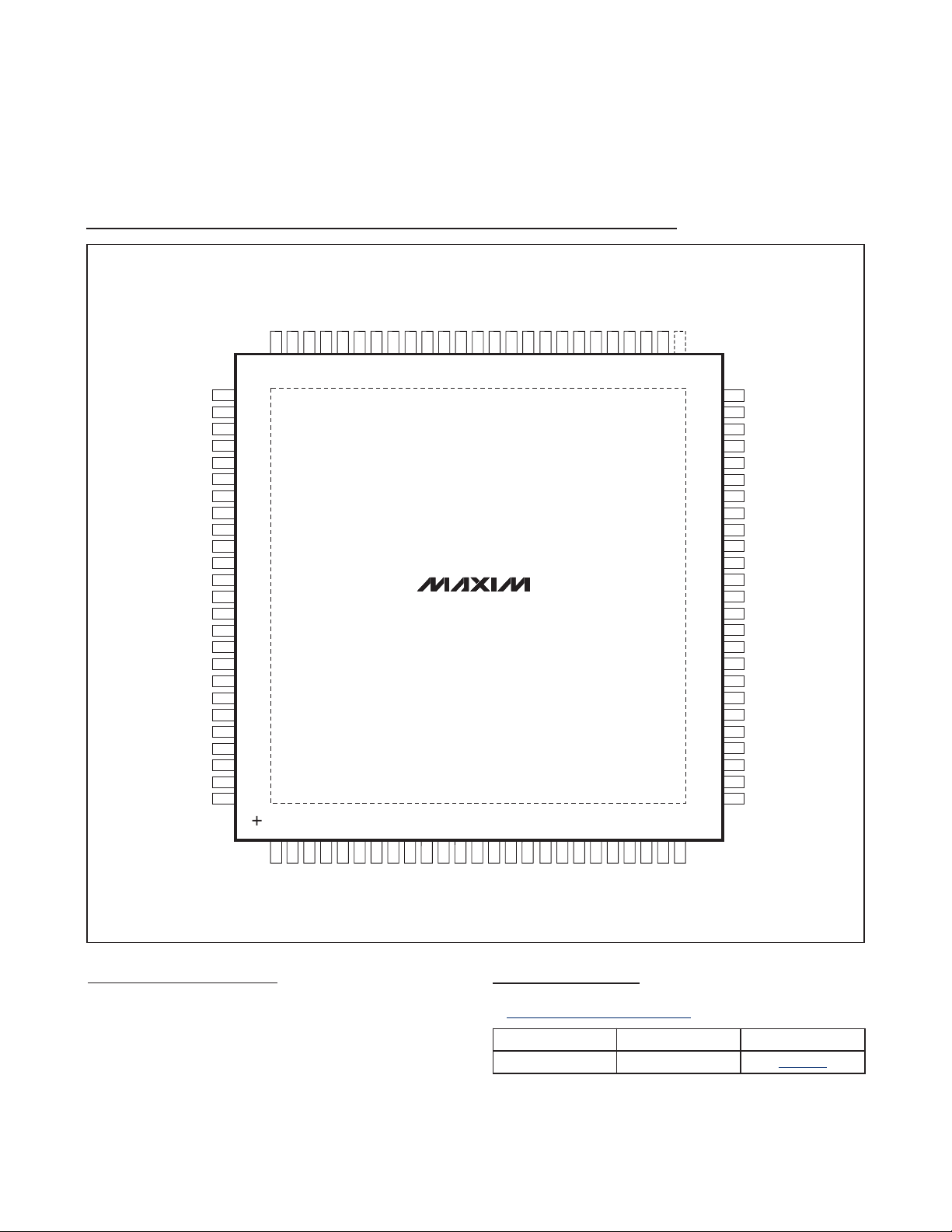
PCB Layout
The pin configuration of the MAX2036 is optimized to
facilitate a very compact physical layout of the device
and its associated discrete components. A typical
application for this device might incorporate several
devices in close proximity to handle multiple channels
of signal processing.
The exposed pad (EP) of the MAX2036’s TQFP-EP
package provides a low thermal-resistance path to the
die. It is important that the PCB on which the MAX2036
is mounted be designed to conduct heat from the EP.
In addition, provide the EP with a low-inductance path
to electrical ground. The EP MUST be soldered to a
ground plane on the PCB, either directly or through an
array of plated via holes.
MAX2036
Ultrasound VGA Integrated
with CW Octal Mixer
______________________________________________________________________________________ 21
Figure 6. Ultrasound IMD3 Measurement Technique
-25dB
ULTRASOUND
IMD3
f1 - (f2 - f1)f
1
f
2
+ (f2 - f1)f
2
Page 22

MAX2036
Ultrasound VGA Integrated
with CW Octal Mixer
22 ______________________________________________________________________________________
Figure 7. Typical per-Channel Ultrasound Imaging Application
TO 10-BIT
IMAGING
ADC
TO I CHANNEL
CWD
ADC
CWD
I CHANNELS
IN
CWD
Q CHANNELS
IN
ADC
CWD
TO Q CHANNEL
VG_CTL+ VG_CTL-
GND
MIX
+V
MIX
+V
115Ω 115Ω
ANTI-ALIAS FILTER.
THIRD-ORDER BUTTERWORTH
REF
V
CC
V
0.1μF
VGOUT_+
50Ω
VGIN_+
0.1μF
50Ω
VGIN_-
VGOUT_-
12μH
CWIN_+
CW_IOUT+
12μH
CW_IOUT-
CWIN_-
CW_QOUT-
CW_QOUT+
CW_VG
CW_FILTER
115Ω 115Ω
CWD I/Q LO
LO DIVIDER
MAX2036
ONE CHANNEL
100nF
100nF
MAX2034
ONE CHANNEL
100nF
-V
D2, D1, D0
ZIN IN CONTROL
100nF
100nF
+V
IN
+V
Page 23
MAX2036
Ultrasound VGA Integrated
with CW Octal Mixer
Maxim cannot assume responsibility for use of any circuitry other than circuitry entirely embodied in a Maxim product. No circuit patent licenses are
implied. Maxim reserves the right to change the circuitry and specifications without notice at any time.
Maxim Integrated Products, 120 San Gabriel Drive, Sunnyvale, CA 94086 408-737-7600 ____________________
23
© 2009 Maxim Integrated Products Maxim is a registered trademark of Maxim Integrated Products, Inc.
CWIN6-
GND
VGIN6-
CWIN5+
VGIN5+
VGIN5-
CWIN2-
1 2 3 4 5 6 7 8 9 10111213141516 171819202122232425
75747372717069686766656463626160595857565554535251
CWIN5-
GND
VGIN6+
V
CC
EXT_C2
EXT_C1
GND
VGIN4+
CWIN4+
CWIN4-
EXT_C3
CWIN3+
CWIN3-
VGIN3-
CWIN2+
GND
VGIN3+
VGIN4-
VGOUT7-
V
CC
LO6
VGOUT6-
GND
LO5
VGOUT2-
VGOUT7+
LO7
76
77
78
79
80
81
82
83
84
85
86
87
88
89
90
91
92
93
94
95
96
97
98
99
100
50
49
48
47
46
45
44
43
42
41
40
39
38
37
36
35
34
33
32
31
30
29
28
27
26
DIN
GND
V
CC
CW_M1
VGIN2+
GND
VGOUT1-
VGOUT1+
LO1
VGOUT8+
LO8
N.C.
V
CC
DOUT
LOW_PWR
M4_EN
V
CC
CW_FILTER
PD
CW_VG
EXT_RES
V
REF
CWIN8+
GND
VGIN8+
VGIN8CWIN7+
CWIN7GND
VGIN7+
VGIN7CWIN6+
VGOUT8-
MAX2036
TOP VIEW
VGOUT6+
VGOUT5-
VG_CTL-
VG_CTL+
LO_LVDS+
LO4
VGOUT4+
VGOUT5+
LO_LVDS-
VGOUT4-
LO3
VGOUT3+
V
CC
LO2
VGOUT2+
VGOUT3-
LOAD
CW_QOUT+
CW_QOUT-
CW_IOUT+
V
CC
VG_CLAMP_MODE
CW_M2
CW_IOUT-
VGIN1+
GND
CWIN1-
VGIN2-
VGIN1-
V
REF
CWIN1+
CLK
CWIN8-
TQFP
Pin Configuration
Package Information
For the latest package outline information and land patterns, go
to www.maxim-ic.com/packages
.
PACKAGE TYPE PACKAGE CODE DOCUMENT NO.
100 TQFP-EP C100E+3
21-0116
Chip Information
PROCESS: Silicon Complementary Bipolar
 Loading...