

Page 1
General Description
The MAX16831 is a current-mode, high-brightness LED
(HBLED) driver designed to control two external
n-channel MOSFETs for the single-string LED current
regulation. The MAX16831 integrates all the building
blocks necessary to implement fixed-frequency HBLED
drivers with wide-range dimming control. The
MAX16831 is configurable to operate as a step-down
(buck), step-up (boost), or step-up/-down (buck-boost)
current regulator.
Current-mode control with leading-edge blanking simplifies control-loop design. Internal slope compensation
stabilizes the current loop when operating at duty cycles
above 50%. The MAX16831 operates over a wide input
voltage range and is capable of withstanding automotive load-dump events. Multiple MAX16831s can be
synchronized to each other or to an external clock. The
MAX16831 includes a floating dimming driver for
brightness control with an external n-channel MOSFET
in series with the LED string.
HBLED drivers using the MAX16831 achieve efficiencies of over 90% in automotive applications. The
MAX16831 also includes a 1.4A source and 2.5A sink
gate driver for driving switching MOSFETs in high-power
LED driver applications, such as front light assemblies.
The dimming control allows for wide PWM dimming at
frequencies up to 2kHz. Higher dimming ratios of up to
1000:1 are achievable at lower dimming frequencies.
The MAX16831 is available in a 32-pin thin QFN package
with exposed pad and operates over the -40°C to
+125°C automotive temperature range.
Applications
Automotive Exterior Lighting:
High-Beam/Low-Beam/Signal Lights
Rear Combination Lights (RCL)
Daytime Running Lights (DRL)
Fog Light and Adaptive Front Light Assemblies
Industrial and Architectural Lighting
Emergency Lighting
Projectors with RGB LED Light Sources
Navigation and Marine Indicators
Features
o Wide Input Range: 6V to 76V With Cold-Start
Operation to 5.5V
o Integrated Differential LED Current-Sense
Amplifier
o Floating Dimming Driver Capable of Driving an
n-Channel MOSFET
o 5% LED Current Accuracy
o 200Hz On-Board Ramp Syncs to External PWM
Dimming Signal
o Programmable Switching Frequency (125kHz to
600kHz) and Synchronization
o Output Overvoltage Load Dump, LED Short,
Overtemperature Protection
o Low 107mV LED Current Sense for High
Efficiency
o Enable/Shutdown Input with Shutdown Current
Below 45µA
MAX16831
High-Voltage, High-Power LED Driver with
Analog and PWM Dimming Control
________________________________________________________________
Maxim Integrated Products
1
19-0809; Rev 0; 4/07
For pricing, delivery, and ordering information, please contact Maxim/Dallas Direct! at
1-888-629-4642, or visit Maxim’s website at www.maxim-ic.com.
Ordering Information
+
Denotes lead-free package.
*
EP = Exposed pad.
V
IN
DIM
R
CS
C
F
R
T
C
REG1
R
UV2
DRV
DRI
REG1
DIM
CS
V
CC
SNS+
FB
QGND
RTSYNC
CS-
CS+
LO
COMP
REG2
DGT
HI
OV
UVEN
SNS-
AGND
R
SENSE
R2
C2
R
OV1
R
OV2
CLMP
SGND
C
CLMP
C
REG2
R1
C1
R
D
LEDs
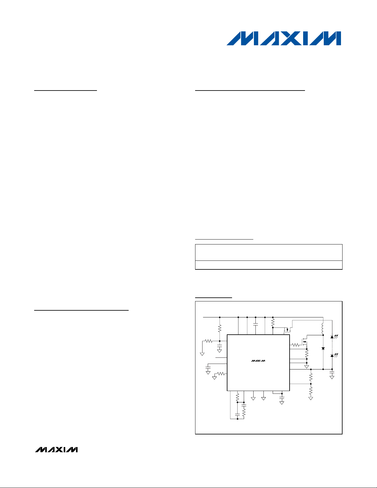
BUCK-BOOST CONFIGURATION
R
UV1
C
UVEN
Q
S
MAX16831
Typical Operating Circuits
Pin Configuration appears at end of data sheet.
Typical Operating Circuits continued at end of data sheet.
PART TEMP RANGE
PINPACKAGE
MAX16831ATJ+ -40°C to +125°C 32 TQFN-EP* T3255M-4
PKG
CODE
Page 2
MAX16831
High-Voltage, High-Power LED Driver with
Analog and PWM Dimming Control
2 _______________________________________________________________________________________
ABSOLUTE MAXIMUM RATINGS
ELECTRICAL CHARACTERISTICS
(VCC= V
UVEN
= 14V, C
REG1
= 1µF, C
REG2
= 1µF, C
CLMP
= 0.1µF, RT= 25kΩ, TA= TJ = -40°C to +125°C, unless otherwise noted.
Typical specifications are at T
A
= +25°C.)
Stresses beyond those listed under “Absolute Maximum Ratings” may cause permanent damage to the device. These are stress ratings only, and functional
operation of the device at these or any other conditions beyond those indicated in the operational sections of the specifications is not implied. Exposure to
absolute maximum rating conditions for extended periods may affect device reliability.
VCC, HI, LO, CLMP to QGND.................................-0.3V to +80V
CS+, CS-, DGT, UVEN to QGND............................-0.3V to +80V
UVEN to QGND ..........................................-0.3V to (V
CC
+ 0.3V)
DRV to SGND .........................................................-0.3V to +18V
DRI, REG2, DIM to AGND ......................................-0.3V to +18V
QGND, SGND to AGND ........................................-0.3V to +0.3V
SNS+ to SNS- ...........................................................-0.3V to +6V
CS, FB, COMP, SNS+, SNS-, OV, REF,
RTSYNC to AGND .................................................-0.3V to +6V
REG1, CLKOUT to AGND ........................................-0.3V to +6V
CS+ to CS- .............................................................-0.3V to +12V
HI to LO ..................................................................-0.3V to +36V
CS+, CS-, DGT, CLMP to LO .................................-0.3V to +12V
CS+, CS-, DGT, CLMP to LO ........................-0.3V to (HI + 0.3V)
HI to CLMP .............................................................-0.3V to +28V
Continuous Power Dissipation* (T
A
= +70°C)
32-Pin TQFN (derate 34.5mW/°C above +70°C) ........2758mW
Thermal Resistance*
θ
JA
.................................................................................29°C/W
θ
JC
................................................................................1.7°C/W
Operating Temperature Range .........................-40°C to +125°C
Maximum Junction Temperature .....................................+150°C
Storage Temperature Range .............................-60°C to +150°C
Reflow Temperature.........................................................+240°C
Lead Temperature (soldering, 10s) .................................+300°C
*As per JEDEC 51 standard, multilayer board (PCB).
Input Voltage Range V
Supply Current I
Shutdown Current I
UVEN
VCC UVLO Threshold
VCC Threshold Hysteresis V
UVEN Threshold
UVEN Input Current I
REGULATORS
REG1 Regulator Output V
REG1 Dropout Voltage I
REG1 Load Regulation ∆V/∆IVCC = 7.5V, 0 ≤ I
REG2 Regulator Output V
REG2 Dropout Voltage I
REG2 Load Regulation ∆V/∆IVCC = 7.5V, 0 ≤ I
HIGH-SIDE REGULATOR (CLMP) (All Voltages Referred to LO) (Note 2)
CLMP UVLO Threshold V
CLMP UVLO Threshold
Hysteresis
PARAMETER SYMBOL CONDITIONS MIN TYP MAX UNITS
CC
I
Q
SHDN
V
CC_R
V
CC_F
CC_HYS
V
UVR
V
UVF
UVEN
REG1
REG2
CLMPTHVCLMP
V
CLMPHYS
V
VCC rising 5.5 6.0
VCC falling 5.0 5.5
V
V
V
0 ≤ I
I
7.5V ≤ VCC ≤ 76V, I
VCC = 5.7V, 0 ≤ I
= 0A 2.7 4.5 mA
REG2
≤ 0.8V 25 45 µA
UVEN
rising 1.100 1.244 1.360
UVEN
falling 1.000 1.145 1.260
UVEN
= 0V and V
UVEN
≤ 2mA, 7.5V ≤ VCC ≤ 76V 4.75 5.00 5.25
REG1
= 2mA, VCC = 5.7V 4.00 4.50 5.25
REG1
= 2mA (Note 1) 0.5 1.0 V
REG1
= 20mA (Note 1) 0.5 V
REG2
rising 2.0 2.5 3.0 V
5.5 76.0 V
0.4 V
= 76V, VCC = 77V -0.2 +0.2 µA
UVEN
≤ 2mA 25 Ω
REG1
= 1mA 6.65 7.00 7.35
REG2
≤ 20mA 4.5 5.0
REG2
≤ 20mA 25 Ω
REG2
0.22 V
V
V
V
V
Page 3
MAX16831
High-Voltage, High-Power LED Driver with
Analog and PWM Dimming Control
_______________________________________________________________________________________ 3
ELECTRICAL CHARACTERISTICS (continued)
(VCC= V
UVEN
= 14V, C
REG1
= 1µF, C
REG2
= 1µF, C
CLMP
= 0.1µF, RT= 25kΩ, TA= TJ = -40°C to +125°C, unless otherwise noted.
Typical specifications are at T
A
= +25°C.)
CLMP Regulator Output Voltage V
CURRENT-SENSE AMPLIFIER (CSA)
Differential Input Voltage Range
Common-Mode Range 0V
CS+ Input Bias Current I
CS- Input Bias Current I
Unity-Gain Bandwidth From (CS+ - CS-) to CS 1.0 MHz
REF OUTPUT BUFFER
REF Output Voltage V
DIM DRIVER
Source Current
Sink Current
GATE DRIVER
DRI UVLO Threshold V
DRI UVLO Threshold Hysteresis V
Driver Output Impedance
Peak Sink Current I
Peak Source Current I
PWM, ILIM, AND HICCUP COMPARATOR
PWM Comparator Offset Voltage V
Peak Current-Limit Comparator
Trip Threshold
Peak Current-Limit Comparator
Propagation Delay (Excluding
Blanking Time)
PARAMETER SYMBOL CONDITIONS MIN TYP MAX UNITS
CLMP
V
-
CS+
V
CS-
CS+
CS-
REF
UVLO_TH
UVLO_HYST
Z
OUT_LVDRI
Z
OUT_HVDRI
SK
SR
8.7V ≤ (V
5.0V ≤ (VHI - VLO) ≤ 8.7V, I
- VLO) ≤ 36V, I
HI
= 1mA 5.5 8.0 10.0
CLMP
(V
- VLO)
CLMP
= 250µA
HI
- 0.7
0 0.3 V
CC
V
- V
CS+
V
CS+
-100µA ≤ I
V
CLMP
V
CLMP
V
CLMP
V
CLMP
= 0.3V -250 +250 µA
CS-
- V
= 0.3V 400 µA
CS-
≤ +100µA 2.85 3.00 3.15 V
REF
- VLO = 4V 5 20
- VLO = 8V 30 67
- VLO = 4V 10 22
- VLO = 8V 40 76
DRI rising 4.0 4.2 4.4 V
0.3 V
= 7.0V, DRV sinking 250mA 2.8 4
= 7.0V, DRV sourcing 250mA 5.0 8
V
= 7.0V 2.5 A
DRI
V
= 7.0V 1.4 A
DRI
COMP
- (V
SNS+
- V
SNS-)
0.7 V
160 200 240 mV
50mV overdrive 40 ns
V
V
mA
mA
Ω
HICCUP Comparator Trip
Threshold
SNS+ Input Bias Current V
SNS- Input Bias Current V
Blanking Time t
BLNK
SNS+
SNS+
= 0V, V
= 0V, V
235 300 385 mV
= 0V -100 -65 µA
SNS-
= 0V -100 -65 µA
SNS-
40 ns
Page 4
MAX16831
High-Voltage, High-Power LED Driver with
Analog and PWM Dimming Control
4 _______________________________________________________________________________________
ELECTRICAL CHARACTERISTICS (continued)
(VCC= V
UVEN
= 14V, C
REG1
= 1µF, C
REG2
= 1µF, C
CLMP
= 0.1µF, RT= 25kΩ, TA= TJ = -40°C to +125°C, unless otherwise noted.
Typical specifications are at T
A
= +25°C.)
ERROR AMPLIFIER
FB Input Bias Current -100 +100 nA
EAMP Output Sink Current VFB = 1.735V, V
EAMP Output Source Current VFB = 0.735V, V
EAMP Input Common-Mode
Voltage
EAMP Output Clamp Voltage 1.1 1.7 2.4 V
Voltage Gain A
Unity-Gain Bandwidth GBW
OSCILLATOR, OSC SYNC, CLK, AND CLKOUT
RTSYNC Frequency Range
RTSYNC Oscillator Frequency
RTSYNC High-Level Voltage V
RTSYNC Low-Level Voltage V
CLKOUT High Level I
CLKOUT Low Level I
CLKOUT Maximum Load
Capacitance
DIM SYNC, DIM RAMP, AND DIM PWM GEN
Internal Ramp Frequency f
External Sync Frequency Range f
External Sync Low-Level Voltage V
External Sync High-Level Voltage V
DIM Comparator Offset V
DIGITAL SOFT-START
Soft-Start Duration t
OVERVOLTAGE COMPARATOR, LOAD OVERCURRENT COMPARATOR
OVP Overvoltage Comparator
Threshold
OVP Overvoltage Comparator
Hysteresis
SLOPE COMPENSATION
Slope Compensation Peak
Voltage Per Cycle
Slope Compensation External clock applied to RTSYNC 15 mV/µs
PARAMETER SYMBOL CONDITIONS MIN TYP MAX UNITS
V
f
SWMIN
f
SWMAX
SIHL
SILL
C
CLK_CAPfSW
RAMP
DIM
LTH
HTH
DIMOS
SS
V
OV
V
OV_HYST
= 1V 3 7 mA
COMP
= 1V 2 7 mA
COMP
0 3.0 V
R
= 100kΩ to AGND 80 dB
COMP
R
= 100kΩ to AGND, C
COMP
to AGND
RT = 25kΩ 475 500 525
R
= 100kΩ 106 125 143
T
= 0.8mA 2.8 V
SINK
= 1.6mA 0.4 V
SOURCE
= 500kHz 500 pF
VOV rising 1.20 1.235 1.27 V
Clock generated by R
T
COMP
= 100pF
0.5 MHz
125
500
2.8 V
0.4 V
160 200 240 Hz
80 2000 Hz
0.4 V
3.2 V
170 200 300 mV
4.0 ms
63.5 mV
120 mV
kHz
kHz
Page 5
MAX16831
High-Voltage, High-Power LED Driver with
Analog and PWM Dimming Control
_______________________________________________________________________________________ 5
ELECTRICAL CHARACTERISTICS (continued)
(VCC= V
UVEN
= 14V, C
REG1
= 1µF, C
REG2
= 1µF, C
CLMP
= 0.1µF, RT= 25kΩ, TA= TJ = -40°C to +125°C, unless otherwise noted.
Typical specifications are at T
A
= +25°C.)
Note 1: Dropout voltage is defined as the input to output differential voltage at which the regulator output voltage drops 100mV below
the nominal output voltage.
Note 2: V
CLMPTH
determines the voltage required to operate the current-sense amplifier. The DIM driver requires 2.5V for (V
CLMP
- VLO)
to drive the external MOSFET. V
HI
is typically one diode drop above V
CLMP
. A large capacitor connected to V
CLMP
slows the
response of the LED current-sense circuitry, resulting in current overshoot. To ensure proper operation, connect a 0.1µF
capacitor from CLMP to LO.
Typical Operating Characteristics
(VCC= V
UVEN
= 14V, C
REG1
= 1µF, C
REG2
= 10µF, C
CLMP
= 0.1µF, RT= 25kΩ, RCS= 0.1Ω, TA= +25°C, unless otherwise noted.)
18
20
19
22
21
24
23
25
27
26
28
-60 -20 0 20-40 40 60 80 120100 140
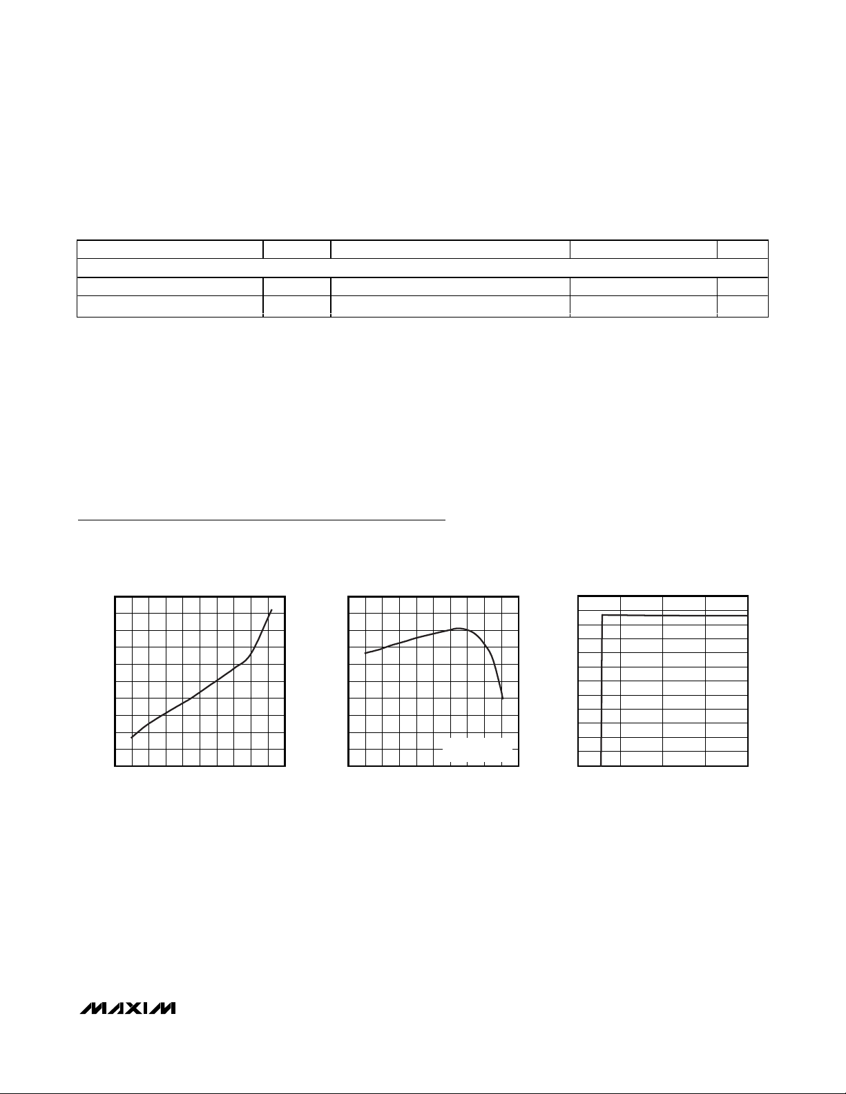
SHUTDOWN CURRENT
vs. TEMPERATURE
MAX16831 toc01
TEMPERATURE (°C)
SHUTDOWN CURRENT (µA)
2.0
2.2
2.1
2.4
2.3
2.6
2.5
2.7
2.9
2.8
3.0
-60 -20 0 20-40 40 60 80 120100 140
OPERATING CURRENT
vs. TEMPERATURE
MAX16831 toc02
TEMPERATURE (°C)
OPERATING CURRENT (mA)
DGT AND DRV NOT
SWITCHING
40
30
20
10
0
70
60
50
80
90
110
100
120
0 10203040
VOLTAGE ACROSS LED CURRENT-SENSE
RESISTOR vs. SUPPLY VOLTAGE
MAX16831 toc03
SUPPLY VOLTAGE (V)
VOLTAGE ACROSS R
CS
(mV)
THERMAL SHUTDOWN
Thermal Shutdown Temperature T
Hysteresis ∆T
PARAMETER SYMBOL CONDITIONS MIN TYP MAX UNITS
SHDN
SHDN
Temperature rising +165 °C
20 °C
Page 6
MAX16831
High-Voltage, High-Power LED Driver with
Analog and PWM Dimming Control
6 _______________________________________________________________________________________
Typical Operating Characteristics (continued)
(VCC= V
UVEN
= 14V, C
REG1
= 1µF, C
REG2
= 10µF, C
CLMP
= 0.1µF, RT= 25kΩ, RCS= 0.1Ω, TA= +25°C, unless otherwise noted.)
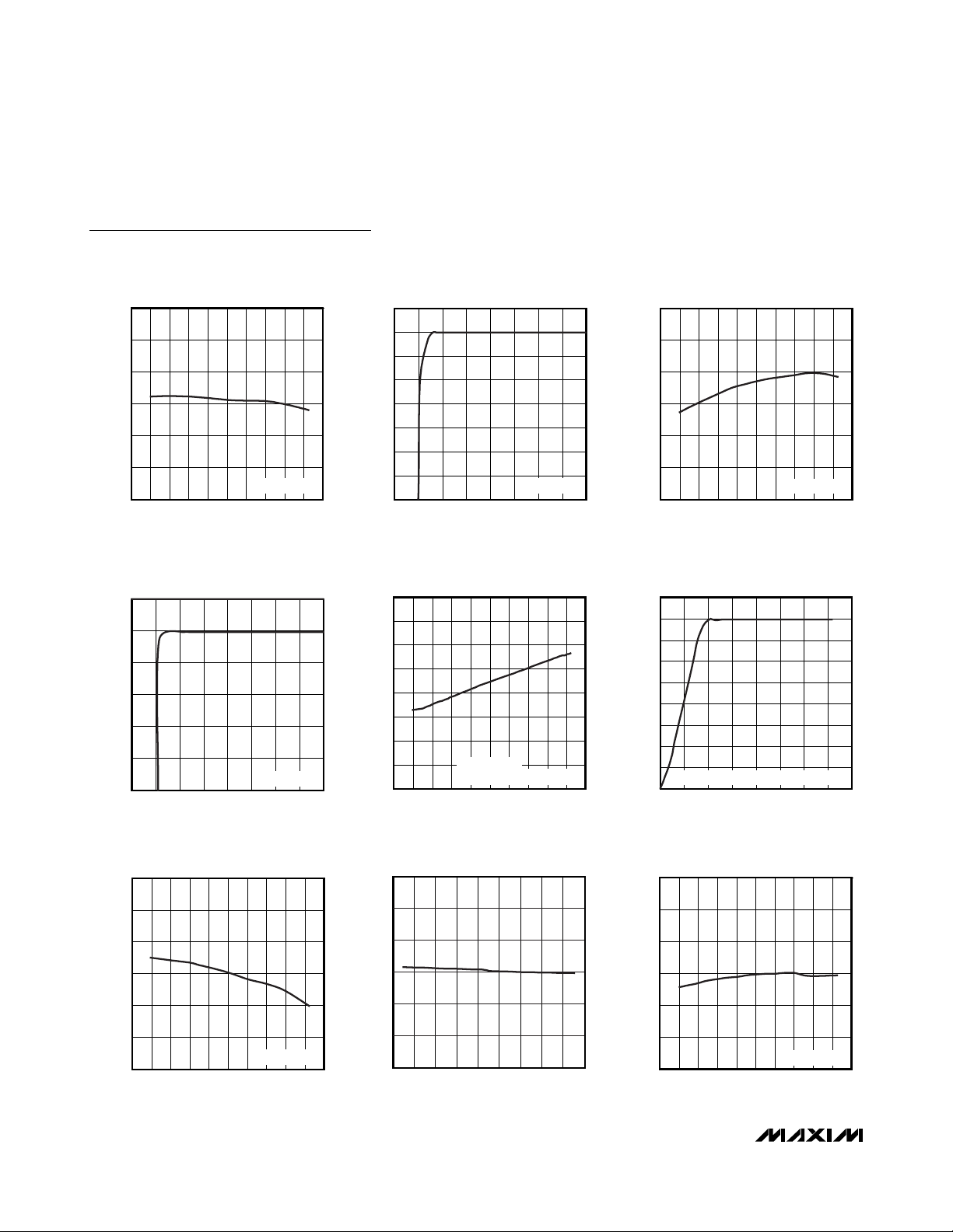
6.80
6.95
6.90
6.85
7.00
7.05
7.10
-60 200-40 -20 40 60 80 100 120 140
REG2 OUTPUT VOLTAGE
vs. TEMPERATURE
MAX16831 toc04
TEMPERATURE (°C)
REG2 OUTPUT VOLTAGE (V)
I
REG2
= 20mA
0
2
1
4
3
5
6
7
8
010155 2025303540
REG2 OUTPUT VOLTAGE
vs. SUPPLY VOLTAGE
MAX16831 toc05
SUPPLY VOLTAGE (V)
REG2 OUTPUT VOLTAGE (V)
I
REG2
= 20mA
4.90
4.96
4.94
4.92
4.98
5.00
5.02
-60 200-40 -20 40 60 80 100 120 140
REG1 OUTPUT VOLTAGE
vs. TEMPERATURE
MAX16831 toc06
TEMPERATURE (°C)
REG1 OUTPUT VOLTAGE (V)
I
REG1
= 2mA
0
1
2
3
4
5
6
0105 152025303540
REG1 OUTPUT VOLTAGE
vs. SUPPLY VOLTAGE
MAX16831 toc07
SUPPLY VOLTAGE (V)
REG1 OUTPUT VOLTAGE (V)
I
REG1
= 2mA
7.5
7.7
7.6
7.8
8.1
8.2
8.0
7.9
8.3
-60 -20 0 20 40-40 60 80 100 120 140
CLMP REGULATOR VOLTAGE
vs. TEMPERATURE
MAX16831 toc08
TEMPERATURE (°C)
CLMP VOLTAGE (V)
VHI - VLO = 11V
CLMP VOLTAGE = V
CLMP
- VLO
1
3
2
5
4
6
7
8
9
010155 2025303540
CLMP REGULATOR VOLTAGE
vs. (V
HI
- VLO)
MAX16831 toc09
VHI - VLO (V)
CLMP REGULATOR VOLTAGE (V)
CLMP REGULATOR VOLTAGE = V
CLMP
- V
LO
2.96
2.99
2.98
2.97
3.00
3.01
3.02
-60 200-40 -20 40 60 80 100 120 140
REF OUTPUT VOLTAGE
vs. TEMPERATURE
MAX16831 toc10
TEMPERATURE (°C)
REF OUTPUT VOLTAGE (V)
I
REF
= 100µA
2.96
2.97
2.99
2.98
3.01
3.00
3.02
-225 -125 -75-175 -25 25 75 125 175 225
REF OUTPUT VOLTAGE
vs. LOAD CURRENT
MAX16831 toc11
LOAD CURRENT (µA)
REF OUTPUT VOLTAGE (V)
470
500
490
480
510
520
530
-60 200-40 -20 40 60 80 100 120 140
PWM OSCILLATOR FREQUENCY
vs. TEMPERATURE
MAX16831 toc12
TEMPERATURE (°C)
PWM FREQUENCY (kHz)
RT = 25kΩ
Page 7

MAX16831
High-Voltage, High-Power LED Driver with
Analog and PWM Dimming Control
_______________________________________________________________________________________
7
Typical Operating Characteristics (continued)
(VCC= V
UVEN
= 14V, C
REG1
= 1µF, C
REG2
= 10µF, C
CLMP
= 0.1µF, RT= 25kΩ, RCS= 0.1Ω, TA= +25°C, unless otherwise noted.)
100
200
250
300
350
400
450
500
550
0.005 0.015 0.025 0.035 0.045
PWM OSCILLATOR FREQUENCY
vs. 1/RT CONDUCTANCE
MAX16831 toc13
1/RT (k
Ω
-1
)
PWM FREQUENCY (kHz)
150
2ms/div
200Hz DIMMING OPERATION
10% DIMMING
1A/div
MAX16831 toc14
0A
50% DIMMING
1A/div
0A
90% DIMMING
1A/div
0A
0
30
40
50
60
70
80
90
100
01 2 3
LED CURRENT DUTY CYCLE
vs. DIM VOLTAGE
MAX16831 toc15
DIM VOLTAGE (V)
LED CURRENT DUTY CYCLE (%)
20
10
40ns/div
DRIVER (DRV) RISE TIME
DRV OUTPUT
RISING
MAX16831 toc16
2V/div
0V
5nF CAPACITOR CONNECTED
FROM DRV TO AGND
40ns/div
DRIVER (DRV) FALL TIME
DRV OUTPUT
FALLING
MAX16831 toc17
2V/div
0V
5nF CAPACITOR CONNECTED
FROM DRV TO AGND
40ns/div
DGT RISE TIME
DGT OUTPUT
RISING
14V OFFSET
MAX16831 toc18
2V/div
14V
VHI - VLO = 11V
1nF CAPACITOR CONNECTED
FROM DGT TO AGND
40ns/div
DGT FALL TIME
DGT OUTPUT
FALLING
14V OFFSET
MAX16831 toc19
2V/div
14V
VHI - VLO = 11V
1nF CAPACITOR CONNECTED
FROM DGT TO AGND
Page 8

MAX16831
High-Voltage, High-Power LED Driver with
Analog and PWM Dimming Control
8 _______________________________________________________________________________________8 _______________________________________________________________________________________
Pin Description
PIN NAME FUNCTION
1, 24 N.C. No Connection. Not internally connected.
Undervoltage Lockout (UVLO) Threshold/Enable Input. UVEN is a dual-function adjustable UVLO
2 UVEN
threshold input with an enable feature. Connect UVEN to V
program the UVLO threshold. Connect UVEN directly to V
threshold. Apply a voltage greater than 1.244V to UVEN to enable the device.
through a resistive voltage-divider to
CC
to use the 6.0V (max) default UVLO
CC
3 REG1
4 AGND Analog Ground
5 REF
6 DIM
7 RTSYNC
8 CLKOUT
9, 10, 11 I.C. Internally Connected. Must be connected to AGND.
12 COMP
13 CS
14 FB Error-Amplifier Inverting Input
15 OV
16, 17 SGND Switching Ground. SGND is the ground for non-analog and high-current gate driver circuitry.
18 DRV Gate Driver Output. Connect DRV to the gate of an external n-channel MOSFET for switching.
19 DRI
20 SNS+
21 SNS-
5V Regulator Output. REG1 is an internal low-dropout voltage regulator that generates a 5V (V
6V) output voltage and supplies power to internal circuitry. Bypass REG1 to AGND through a 1µF
ceramic capacitor.
Accurate 3V Buffered Reference Output. Connect REF to DIM through a resistive voltage-divider to
apply a DC voltage for analog-controlled dimming functionality. Leave REF unconnected if unused.
Dimming Control Input. Connect DIM to an external PWM signal for PWM dimming. For analogcontrolled dimming, connect DIM to REF through a resistive voltage-divider. The dimming frequency
is 200Hz under these conditions. Connect DIM to AGND to turn off the LEDs.
SYNC Input/Output. The PWM clock is generated by the RTSYNC oscillator. Connect an external
resistor to RTSYNC to select a clock switching frequency from 125kHz to 600kHz or connect RTSYNC
to an external clock to synchronize the MAX16831 with a master clock signal.
Clock Output. CLKOUT buffers the oscillator/clock. Connect CLKOUT to the SYNC input of another
device to operate the MAX16831 in a multichannel configuration. CLKOUT is a logic output.
Error-Amplifier Output. Connect the compensation network from COMP to FB for stable closed-loop
control. Use low-leakage ceramic capacitors in the feedback network.
Current-Sense Amplifier Output. The current-sense amplifier (CSA) senses the differential voltage
across the load sense resistor, R
current. Connect the proper compensation resistor from CS to FB.
Overvoltage Protection Input. Connect OV to HI through a resistive voltage-divider to set the
overvoltage limit for the load. When the voltage at OV exceeds the 1.235V (typ) threshold, an
overvoltage fault is generated and the switching MOSFET turns off. The MOSFET is turned on again
when the voltage at OV drops below 1.17V (typ).
Gate Driver Supply Input. Connect DRI to REG2 to power the primary switching MOSFET driver.
Bypass DRI to AGND through a 10µF ceramic capacitor.
Positive Peak Current-Sense Input. Connect SNS+ to the positive side of the switch current-sense
resistor, R
Negative Peak Current-Sense Input. Connect SNS- to the negative side of the switch current-sense
resistor, R
SENSE
SENSE
.
.
, and generates a voltage, VCS, at CS proportional to the LED
CS
CC
>
Page 9

MAX16831
High-Voltage, High-Power LED Driver with
Analog and PWM Dimming Control
_______________________________________________________________________________________ 9
Detailed Description
The MAX16831 is a current-mode PWM LED driver
used for driving HBLEDs. By using two current regulation loops, 5% output current accuracy is achieved.
One current regulation loop controls the external
switching MOSFET peak current through a sense resistor, R
SENSE
, from SNS+ to SNS-, while the other current
regulation loop controls the average LED string current
through the sense resistor RCSin series with the LEDs.
The wide operating supply range of (6.0V/5.5V
ON/OFF) up to 76V makes the MAX16831 ideal in automotive applications.
The MAX16831 features a programmable undervoltage
lockout (UVEN) that ensures predictable operation during brownout conditions. The input UVEN circuit monitors the supply voltage, VCC, and turns the driver off
when V
CC
drops below the UVLO threshold. Connect
UVEN to V
CC
to use the 5.7V (typ) default UVLO thresh-
old. The MAX16831 includes a cycle-by-cycle current
limit that turns off the gate drive to the external switching MOSFET (Q
S
) during an overcurrent condition. The
MAX16831 features a programmable oscillator that simplifies and optimizes the design of external magnetics.
The MAX16831 includes three internal voltage regulators, REG1, REG2, and CLMP, and a 3V buffered reference output, REF. Connect REG2 to the driver supply,
DRI, to power the switching MOSFET driver.
The MAX16831 is capable of synchronizing with an
external clock or operating in stand-alone mode. A single resistor, R
T
, can be used to adjust the switching frequency from 125kHz to 600kHz for stand-alone
operation. To synchronize the device with an external
clock, apply a clock signal directly to the RTSYNC
input. A buffered clock output, CLKOUT, is available to
configure the MAX16831 in multichannel applications.
_______________________________________________________________________________________ 9
Pin Description (continued)
PIN NAME FUNCTION
22 QGND Analog Ground. Ensure a low-impedance connection between QGND and AGND.
23 DGT
25 LO
26 CS+
27 CS-
28 CLMP
29 HI
30 REG2
31 V
32 I.C. Internally Connected. Must be connected directly to QGND.
—EP
CC
Dimming Gate Driver Output. Connect DGT to the gate of an external n-channel MOSFET for
dimming. DGT is powered by the internal regulator, CLMP, and is referenced to LO.
Low-Voltage Input. LO is the return point for the LED current. When using the MAX16831 in a buckboost configuration, connect LO to V
connect LO to SGND. Connect LO to the junction of the inductor and LED current-sense resistor,
R
, when using a buck configuration.
CS
Noninverting Current-Sense Amplifier Input. Connect CS+ to the positive side of an external sense
resistor, R
Inverting Current-Sense Amplifier Input. Connect CS- to the negative side of an external sense
resistor, R
Internal CLMP Regulator Output. CLMP supplies an 8V (typ) output when V
9V, V
provides the high reference for the dimming driver. V
enable the current-sense amplifier and dimming MOSFET driver. Bypass CLMP to LO with a 0.1µF
ceramic capacitor.
High-Voltage Input. HI is referred to LO. HI supplies power to the current-sense amplifier and
dimming MOSFET gate driver through the CLMP regulator.
Internal Regulator Output. REG2 is an internal voltage regulator that generates a 7V output and
supplies power to internal circuitry. Connect REG2 to DRI to power the switching MOSFET driver
during normal operation. Bypass REG2 to AGND with a 10µF ceramic capacitor.
Supply Voltage Input
Exposed Pad. Connect EP to AGND. EP also functions as a heatsink to maximize thermal dissipation.
Do not use as a ground connection.
, connected in series with the load (LEDs).
CS
, connected in series with the load (LEDs).
CS
is one diode drop below VHI. The CLMP regulator powers the current-sense amplifier and
CLMP
. When using the device in a boost configuration only,
CC
≥ 9V. If VHI is lower than
HI
must be at least 2.5V higher than VLO to
CLMP
Page 10

MAX16831
The MAX16831 features a differential high-side level
shifter to drive an external n-channel MOSFET for dimming. Wide contrast “pulsed” dimming (1000:1) is possible by applying either a low-frequency PWM input
signal or a DC voltage to the dimming input (DIM).
Protection features include peak current limiting,
HICCUP mode current limiting, output overvoltage protection, short-circuit protection, and thermal shutdown.
The HICCUP current-limit circuitry reduces the power
delivered to the load during severe fault conditions.
Nonlatching overvoltage protection limits the voltage on
the external switching MOSFET (Q
S
) under open-circuit
conditions in the LED string. During continuous operation at high input voltages, the power dissipation of the
MAX16831 could exceed the maximum rating and an
internal thermal shutdown circuitry safely turns off the
MAX16831 when the device junction temperature
exceeds +165°C. When the junction temperature drops
below the hysteresis temperature, the MAX16831 automatically re-initiates startup.
Undervoltage Lockout/Enable
The MAX16831 features a dual-purpose adjustable
UVLO input and enable function. Connect UVEN to V
CC
through a resistive voltage-divider to set the undervoltage lockout (UVLO) threshold. The MAX16831 is
enabled when the UVEN exceeds the 1.244V (typ)
threshold. Drive UVEN to ground to disable the output.
Setting the UVLO Threshold
The MAX16831 features a programmable UVLO threshold. Connect UVEN directly to VCCto select the default
6.0V (max) UVLO threshold. Connect UVEN to V
CC
through a resistive voltage-divider to select a UVLO
threshold (Figure 1). Calculate resistor values as follows:
where R
UV1
+ R
UV2
≤ 270kΩ, V
UVEN
is the 1.244V (typ)
threshold voltage, and V
UVLO
is the desired UVLO
threshold in volts at VCC(Figure 1).
The capacitor, C
UVEN
, is required to prevent chattering
at the UVLO threshold due to line impedance drops
during power-up and dimming. If the undervoltage setting is very close to the required minimum operating
voltage, then there can be jumps in the voltage at V
CC
during dimming, which may cause the MAX16831 to
turn on and off when the dimming signal transitions
from low to high. The capacitor, C
UVEN
, should be
large enough to limit the ripple on UVEN to less than
the 100mV (min) UVEN hysteresis so that the device
does not turn off under these circumstances.
Soft-Start
The MAX16831 includes a factory-set 4ms (typ) softstart delay that allows the load current to ramp up in a
controlled manner, minimizing output overshoot. Softstart begins once the device is enabled and V
CC
exceeds the UVLO threshold. Soft-start circuitry slowly
increases the internal soft-start voltage, VSS, resulting
in a controlled rise of the load current. Signals applied
to DIM are ignored until the soft-start duration is complete and a successive delay of 200µs has elapsed.
Internal Regulators
The MAX16831 includes a fixed 5V voltage regulator
REG1, a 7V voltage regulator REG2, and an internal 8V
regulator CLMP. REG1 and REG2 power up when V
CC
exceeds the UVLO threshold. REG1 supplies power to
internal circuitry and remains on during PWM dimming.
It is capable of driving external loads up to 2mA.
REG2 is capable of delivering up to 20mA of current.
Connect REG2 to DRI to generate the supply voltage
for the primary switching MOSFET driver, DRV.
CLMP is powered by HI and supplies power to the current-sense amplifier (CSA). CSA is enabled when
V
CLMP
goes 2.5V above VLOand is disabled when
(V
CLMP
- VLO) falls below 2.28V. The CLMP regulator
also provides power to the dimming MOSFET control
circuitry. CLMP is the output of the CLMP regulator. Do
not use CLMP to power external circuitry. Bypass
CLMP to LO with a 0.1µF ceramic capacitor. A larger
capacitor will result in overshoots of the load current.
High-Voltage, High-Power LED Driver with
Analog and PWM Dimming Control
10 ______________________________________________________________________________________
Figure 1. Setting the UVLO Threshold
⎛
V
RR
=×
UV UV
12
UVEN
⎜
VV
⎝
-
UVLO UVEN
⎞
⎟
⎠
V
IN
R
UV2
UVEN
C
UVEN
R
UV1
V
CC
MAX16831
QGND
Page 11

Reference Voltage Output
The MAX16831 includes a 5% accurate 3V (typ)
buffered reference output, REF. REF is a push-pull output capable of sourcing/sinking 100µA of current and
can drive a maximum load capacitance of 100pF.
Connect REF to DIM through a resistive voltage-divider
to supply an analog signal for dimming. See the
Dimming Input (DIM)
section.
Dimming MOSFET Driver (DDR)
The MAX16831 requires an external n-channel
MOSFET for PWM dimming. Connect the MOSFET to
the output of the DDR dimming driver, DGT, for normal
operation. V
DGT
swings between VLOand V
CLMP
. The
DDR dimming driver is capable of sinking or sourcing
up to 20mA of current. The average current required to
drive the dimming MOSFET (I
DRIVE_DIM
) depends on
the MOSFET’s total gate charge (Q
G_DIM
) and the dim-
ming frequency of the converter, f
DIM
. Use the following equation to calculate the average gate drive current
for the n-channel dimming FET.
I
DRIVE_DIM
= Q
G_DIM
x f
DIM
n-Channel MOSFET Switch Driver (DRV)
The MAX16831 drives an external n-channel MOSFET.
Use an external supply or connect REG2 to DRI to
power the MOSFET driver. The driver output, V
DRV
,
swings between ground and V
DRI
. Ensure that V
DRI
remains below the absolute maximum VGSrating of the
external MOSFET. DRV is capable of sinking 2.5A or
sourcing 1.4A of peak current, allowing the MAX16831
to switch MOSFETs in high-power applications. The
average current sourced to drive the external MOSFET
depends on the total gate charge (QG) and operating
frequency of the converter, fSW. The power dissipation
in the MAX16831 is a function of the average output
drive current (I
DRIVE
). Use the following equations to
calculate the power dissipation in the gate driver section of the MAX16831 due to I
DRIVE
:
I
DRIVE
= QGx f
SW
PD= (I
DRIVE
+ ICC) x V
DRI
where V
DRI
is the supply voltage to the gate driver and
ICCis the operating supply current. I
DRIVE
should not
exceed 20mA.
Dimming Input (DIM)
The dimming input, DIM, functions with either analog or
PWM control signals. Once the internal pulse detector
detects three successive edges of a PWM signal with a
frequency between 80Hz and 2kHz, the MAX16831 synchronizes to the external signal and pulse-width-modulates the LED current at the external DIM input frequency
with the same duty cycle as the DIM input. If an analog
control signal is applied to DIM, the MAX16831 compares the DC input to an internally generated 200Hz
ramp to pulse-width-modulate the LED current (f
DIM
=
200Hz). The output current duty cycle is linearly
adjustable from 0 to 100% (0.2V < V
DIM
< 2.8V).
Use the following formula to calculate the voltage, V
DIM
,
necessary for a given output-current duty cycle, D:
V
DIM
= (D x 2.6) + 0.2V
where V
DIM
is the voltage applied to DIM in volts.
Connect DIM to REF through a resistive voltage-divider
to apply a DC DIM control signal (Figure 2). Use the
required dimming input voltage, V
DIM
, calculated
above and select appropriate resistor values using the
following equation:
R4= R3x V
DIM
/ (V
REF
- V
DIM
)
where V
REF
is the 3V reference output voltage and
30kΩ≤R3+ R4≤ 150kΩ.
For proper operation at startup or after toggling ENABLE,
the controller needs three clock edges or an analog voltage greater than 0.3V on the DIM input.
Oscillator, Clock, and Synchronization
The MAX16831 is capable of stand-alone operation or
synchronizing to an external clock, and driving external
devices in SYNC mode. For stand-alone operation, program the switching frequency by connecting a single
external resistor, RT, between RTSYNC and ground.
Select the switching frequency, fSW, from 125kHz to
600kHz and calculate RTusing the following formula:
where the switching frequency is in kHz and RT is in kΩ.
The MAX16831 is also capable of synchronizing to an
external clock signal ranging from 125kHz to 600kHz.
MAX16831
High-Voltage, High-Power LED Driver with
Analog and PWM Dimming Control
______________________________________________________________________________________ 11
Figure 2. Creating a DIM Input Signal from REF
REF
R
3
R
4
DIM
MAX16831
AGND
kHz
500
R
=×
T
f
SW
25 Ω
k
Page 12
MAX16831
Connect the clock signal to the RTSYNC input. The
MAX16831 synchronizes to the external clock signal
after the detection of five successive clock edges at
RTSYNC.
A buffered clock output, CLKOUT, is capable of driving
the RTSYNC input of an external PWM controller for
multichannel applications. CLKOUT is capable of driving capacitive loads up to 500pF.
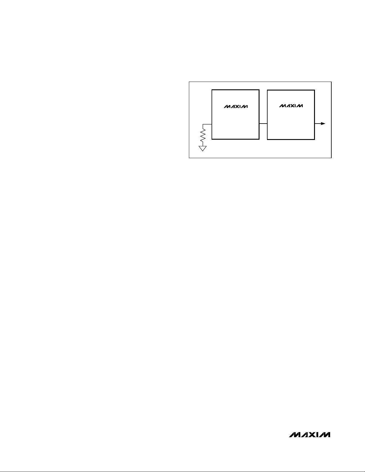
Multichannel Configuration
The MAX16831 is capable of multichannel operation.
Connect CLKOUT to the SYNC input of an external
device to use the MAX16831 as a master clock signal.
Connect an external clock signal to RTSYNC to configure the MAX16831 as a slave. To setup two or more
MAX16831 devices in a daisy-chain/peer-to-peer configuration, drive the RTSYNC input of one MAX16831
with the CLKOUT buffer of another (Figure 3).
ILIM and HICCUP Comparator
R
SENSE
sets the peak current through the inductor for
switching. The differential voltage across R
SENSE
is
compared to the 200mV voltage trip limit of the currentlimit comparator, ILIM. Set the current limit 20% higher
than the peak switch current at the rated output power
and minimum voltage. Use the following equation to
calculate R
SENSE
:
R
SENSE
= V
SENSE
/ (1.2 x I
PEAK
)
where V
SENSE
is the 200mV differential voltage
between SNS+ and SNS- and I
PEAK
is the peak induc-
tor current at full load and minimum input voltage.
When the voltage drop across R
SENSE
exceeds the
ILIM threshold, the MOSFET driver (DRV) terminates
the on-cycle and turns the switch off, reducing the current through the inductor. The FET is turned back on at
the beginning of the next switching cycle.
When the voltage across R
SENSE
exceeds the 300mV
(typ) HICCUP threshold, the HIC comparator terminates
the on-cycle of the device, turning the switching
MOSFET off. Following a startup delay of 4ms (typ), the
MAX16831 re-initiates soft-start. The device will continue to operate in HICCUP mode until the overcurrent
condition is removed.
A built-in 40ns leading-edge blanking circuit of the current-sense signal prevents these comparators from prematurely terminating the on-cycle of the external
switching MOSFET (QS). In some cases, this blanking
time may not be adequate and an additional RC filter
may be required to prevent spurious turn-off.
Load Current Sense
The load-sense resistor, RCS, monitors the current
through the LEDs. The internal floating current-sense
amplifier, CSA, measures the differential voltage across
RCS, and generates a voltage proportional to the LED
current through RCSat CS. This voltage on CS is
referred to AGND. The closed loop regulates the LED
current to a value, I
LED
, given by the following equation:
I
LED
= 0.107V / R
CS
Slope Compensation
The MAX16831 uses an internal ramp generator for
slope compensation. The internal ramp signal is reset
to zero at the beginning of each cycle and has a peakto-peak voltage of 120mV per switching cycle. Use an
external resistor, RT, to set the switching frequency,
fSW, and calculate the slope of the compensating ramp,
m
SLOPE
, using the following equation:
m
SLOPE
= 120 x fSW[mV/s]
where fSWis the switching frequency in Hz. When the
MAX16831 is synchronized to an external clock, the
slope compensation ramp has a slope of 15mV/µs.
Internal Voltage-Error Amplifier (EAMP)
The MAX16831 includes a built-in voltage amplifier,
with tri-state output, which can be used to close the
feedback loop. The buffered output current-sense signal appears at CS, which is connected to the inverting
input, FB, of the error amplifier through resistor R1. The
noninverting input is connected to an internally trimmed
current reference.
The output of the error amplifier is controlled by the signal applied to DIM. When DIM is high, the output of the
amplifier is connected to COMP. The amplifier output is
open when DIM is low. This enables the integrating
High-Voltage, High-Power LED Driver with
Analog and PWM Dimming Control
12 ______________________________________________________________________________________
Figure 3. Master-Slave/Peer-Peer Clock Configuration
MASTER/PEER
MAX16831
RTSYNC
R
T
CLKOUT
SLAVE/PEER
MAX16831
RTSYNC
CLKOUT
Page 13

capacitor to hold the charge when the DIM signal has
turned off the gate drive. When DIM is high again, the
voltage on the compensation capacitors, C1 and C2,
will force the converter into steady-state instantaneously.
PWM Dimming
PWM dimming is achieved by driving DIM with either a
PWM signal or a DC signal. The PWM signal is internally connected to the error amplifier, the dimming
MOSFET gate driver, and the switching MOSFET gate
driver. When the DIM signal is high, the dimming
MOSFET and the switching MOSFET drivers are
enabled and the output of the voltage-error amplifier is
connected to the external compensation network. Also,
the buffered current-sense signal is connected to CS.
Preventing discharge of the compensation capacitor
when the DIM signal is low will allow the control loop to
return the LED current to its original value almost
instantaneously.
When the DIM signal goes low, the output of the error
amplifier is disconnected from the compensation network and the voltage of compensation capacitors, C1
and C2 is preserved. Choose low-leakage capacitors
for C1 and C2. The drivers for the external dimming
and switching MOSFETs are disabled, and the converter stops switching. The inductor energy is now transferred to the output capacitors.
When the DIM signal goes high and the gate drivers are
enabled, the additional voltage on the output capacitor
may cause a current spike on the LED string. A larger
output capacitor will result in a smaller current spike. The
MAX16831 thus achieves fast PWM dimming response.
Fault Protection
The MAX16831 features built-in overvoltage protection,
overcurrent protection, HICCUP mode current-limit protection, and thermal shutdown. Overvoltage protection
is achieved by connecting OV to HI through a resistive
voltage-divider. HICCUP mode limits the power dissipation in the external MOSFETs during severe fault
conditions. Internal thermal shutdown protection safely
turns off the converter when the junction temperature
exceeds +165°C.
Overvoltage Protection
The overvoltage protection (OVP) comparator compares the voltage at OV with a 1.235V (typ) internal reference. When the voltage at OV exceeds the internal
reference, the OVP comparator terminates PWM
switching and no further energy is transferred to the
load. The MAX16831 re-initiates soft-start once the
overvoltage condition is removed. Connect OV to HI
through a resistive voltage-divider to set the overvoltage threshold at the output.
Setting the Overvoltage Threshold
Connect OV to HI or to the high-side of the LEDs
through a resistive voltage-divider to set the overvoltage threshold at the output (Figure 4). The overvoltage
protection (OVP) comparator compares the voltage at
OV with a 1.235V (typ) internal reference. Use the following equation to calculate resistor values:
where VOVis the 1.235V OV threshold. Choose R
OV1
and R
OV2
to be reasonably high-value resistors to prevent discharge of filter capacitors. This will prevent
unnecessary undervoltage and overvoltage conditions
during dimming.
Load-Dump Protection
The MAX16831 features load-dump protection up to
80V. LED drivers using the MAX16831 can sustain single fault load dump events. Repeated load dump events
within very short time intervals can cause damage to the
dimming MOSFET due to excess power dissipation.
Thermal Shutdown
The MAX16831 contains an internal temperature sensor
that turns off all outputs when the die temperature
exceeds +165°C. Outputs are enabled again when the
die temperature drops below +145°C.
MAX16831
High-Voltage, High-Power LED Driver with
Analog and PWM Dimming Control
______________________________________________________________________________________ 13
Figure 4. Setting the Overvoltage Threshold
V
LED+
R
OV1
R
OV2
MAX16831
OV
AGND
VV
⎛
RR
=×
OV OV
12
OV LIM OV
⎜
⎝
-
_
V
OV
⎞
⎟
⎠
Page 14

MAX16831
Applications Information
Inductor Selection
The minimum required inductance is a function of operating frequency, input-to-output voltage differential, and
the peak-to-peak inductor current (∆I
L
). Higher ∆I
L
allows for a lower inductor value while a lower ∆I
L
requires a higher inductor value. A lower inductor value
minimizes size and cost, improves large-signal transient response but reduces efficiency due to higher
peak currents and higher peak-to-peak output ripple
voltage for the same output capacitance. On the other
hand, higher inductance increases efficiency by reducing the ripple current, ∆IL. However, resistive losses
due to extra turns can exceed the benefit gained from
lower ripple current levels, especially when the inductance is increased without also allowing for larger
inductor dimensions. A good compromise is to choose
∆ILequal to 30% of the full load current. The inductor
saturating current is also important to avoid runaway
current during the output overload and continuous
short circuit. Select the I
SAT
to be higher than the maxi-
mum peak current limit.
Buck configuration: In a buck configuration, the average inductor current does not vary with the input. The
worst-case peak current occurs at a high input voltage.
In this case, the inductance L for continuous conduction mode is given by:
where V
INMAX
is the maximum input voltage, fSWis the
switching frequency, and V
OUT
is the output voltage.
Boost configuration: In the boost converter, the average
inductor current varies with line and the maximum average current occurs at low line. For the boost converter,
the average inductor current is equal to the input current. In this case, the inductance L is calculated as:
where V
INMIN
is the minimum input voltage, V
OUT
is the
output voltage, and fSWis the switching frequency.
Buck-boost configuration: In a buck-boost converter,
the average inductor current is equal to the sum of the
input current and the load current. In this case, the
inductance L is:
where V
INMIN
is the minimum input voltage, V
OUT
is the
output voltage, and fSWis the switching frequency.
Output Capacitor
The function of the output capacitor is to reduce the
output ripple to acceptable levels. The ESR, ESL, and
the bulk capacitance of the output capacitor contribute
to the output ripple. In most of the applications, the output ESR and ESL effects can be dramatically reduced
by using low-ESR ceramic capacitors. To reduce the
ESL effects, connect multiple ceramic capacitors in
parallel to achieve the required bulk capacitance.
In a buck configuration, the output capacitance, CF, is
calculated using the following equation:
where ∆V
R
is the maximum allowable output ripple.
In a boost configuration, the output capacitance, CF, is
calculated as:
where I
OUT
is the output current.
In a buck-boost configuration, the output capacitance,
CF, is calculated as:
where V
OUT
is the voltage across the load and I
OUT
is
the output current. Connect the output capacitor(s)
from the output to ground in a buck-boost configuration
(not across the load as for other configurations).
Input Capacitor
An input capacitor connected between UVEN and
ground must be used when configuring the MAX16831
as a buck converter. Use a low-ESR input capacitor
that can handle the maximum input RMS ripple current.
Calculate the maximum allowable RMS ripple using the
following equation:
In most of the cases, an additional electrolytic capacitor should be added to prevent input oscillations due to
line impedances.
High-Voltage, High-Power LED Driver with
Analog and PWM Dimming Control
14 ______________________________________________________________________________________
VV V
×
()-
OUT INMAX OUT
L
=
VfI
××
INMAX SW L
VVV
L
=
×
INMIN OUT INMIN
()-
Vf I
××
OUT SW L
∆
VV
×
L
=
OUT INMIN
VV fI
+××()∆
OUT INMIN SW L
∆
VVV
()-
C
INMAX OUT OUT
≥
F
VLV f
××× ×
∆ 2
R INMAX SW
×
VV I
()-2
C
OUT INMIN OUT
≥
F
VV f
∆
R OUT SW
××
××
VI
××
2
OUT OUT
×+ ×
C
≥
F
VV V f
∆ ()
R OUT INMIN SW
×× -
I VVV
OUT OUT INMIN OUT
I
IN RMS
=
()
()
V
INMIN
2
Page 15

When using the MAX16831 in a boost or buck-boost
configuration, the input RMS current is low and the
input capacitance can be small.
Operating the MAX16831 Without the
Dimming Switch
The MAX16831 can also be used in the absence of the
dimming MOSFET. In this case, the PWM dimming performance is compromised but in applications that do
not require dimming, the MAX16831 can still be used.
A short circuit across the load will cause the MAX16831
to disable the gate drivers and they will remain off until
the input power is recycled.
Switching Power MOSFET Losses
When selecting MOSFETs for switching, consider the
total gate charge, power dissipation, the maximum
drain-to-source voltage, and package thermal impedance. The product of the MOSFET gate charge and
R
DS(ON)
is a figure of merit, with a lower number signifying better performance. Select MOSFETs optimized
for high-frequency switching applications.
MOSFET losses may be broken into three categories:
conduction loss, gate drive loss, and switching loss.
The following simplified power loss equation is true for
all the different configurations.
P
LOSS
= P
CONDUCTION
+ P
GATEDRIVE
+ P
SWITCH
Layout Recommendations
Typically, there are two sources of noise emission in a
switching power supply: high di/dt loops and high dv/dt
surfaces. For example, traces that carry the drain current often form high di/dt loops. Similarly, the heatsink
of the MOSFET connected to the device drain presents
a high dv/dt source; therefore, minimize the surface
area of the heatsink as much as possible. Keep all PCB
traces carrying switching currents as short as possible
to minimize current loops. Use ground planes for best
results.
Careful PCB layout is critical to achieve low switching
losses and clean, stable operation. Use a multilayer
board whenever possible for better noise performance
and power dissipation. Follow these guidelines for
good PCB layout:
• Use a large copper plane under the MAX16831
package. Ensure that all heat-dissipating components have adequate cooling. Connect the exposed
pad of the device to the ground plane.
• Isolate the power components and high-current paths
from sensitive analog circuitry.
• Keep the high-current paths short, especially at the
ground terminals. This practice is essential for stable, jitter-free operation. Keep switching loops short.
• Connect AGND, SGND, and QGND to a ground
plane. Ensure a low-impedance connection between
all ground points.
• Keep the power traces and load connections short.
This practice is essential for high efficiency. Use
thick copper PCBs (2oz vs. 1oz) to enhance full-load
efficiency.
• Ensure that the feedback connection to FB is short
and direct.
• Route high-speed switching nodes away from the
sensitive analog areas.
• To prevent discharge of the compensation capacitors, C1 and C2, during the off-time of the dimming
cycle, ensure that the PCB area close to these components has extremely low leakage. Discharge of
these capacitors due to leakage may result in
degraded dimming performance.
Chip Information
PROCESS: BICMOS
MAX16831
High-Voltage, High-Power LED Driver with
Analog and PWM Dimming Control
______________________________________________________________________________________ 15
Pin Configuration
TOP VIEW
N.C.
1
2
UVEN
3
REG1
AGND
4
5
REF
6
DIM
RTSYNC
7
8
CLKOUT
*EP = EXPOSED PAD
CC
V
I.C.
32 31 30 29 28 27 26
+
*EP
9 101112131415
I.C.
REG2
MAX16831
I.C.
I.C.
TQFN
(5mm x 5mm)
HI
COMP
CLMP
CS
CS-
FB
CS+
OV
16
25
LO
SGND
N.C.
24
23
DGT
22
QGND
21
SNS-
20
SNS+
19
DRI
DRV
18
17
SGND
Page 16

MAX16831
High-Voltage, High-Power LED Driver with
Analog and PWM Dimming Control
16 ______________________________________________________________________________________
Functional Diagram
UVEN
QGND
REG1
REF
RTSYNC
CLKOUT
DIM
AGND
V
OV
OV
-
OVP
+
200Hz
-
OSC
200mV
V
BUF
V
CC
UVLO
AND
EN
SHUTDOWN
-
3.0V
+
+
THERMAL
OSC
+
COMP
-
5V
REG1
SLOPE
COMP
POR
EN
OV
MAX16831
CLMP
7V
REG2
OC
SLOPE
+
CMP
-
CONTROL
BLOCK
CLMP
1.3 x V
UGB
SS
ILIM
HIC
+
-
-
+
-
-
HI
200mV
300mV
BLANKING
TIME
40ns
V
V
DDR
CLMP
CLMP
V
LO
CS-
CSA
DRIVER
CS+
10uA
LO
+
V
LO
REG2
R
LS
V
CLMP
DGT
TRI
CS
DRI
DRV
SGND
SNS+
SNS-
EAMP
PWM
SLOPE
-
600mV
+
INTERNAL
TRIM
SS
V
V
OV
SS
X1
COMP
FB
Page 17

MAX16831
V
IN
R
CS
C
F
R
T
C
REG1
R
UV2
DRV
DRI
REG1
CS
V
CC
SNS+
FB
QGND
RTSYNC
CS-
CS+
LO
COMP
REG2
DGT
OV
UVEN
SNS-
AGND
R
SENSE
R2
C2
R
OV1
R
OV2
CLMP
SGND
C
CLMP
C
REG2
R1
C1
R
D
LEDs
BOOST CONFIGURATION
R
UV1
C
UVEN
Q
S
MAX16831
R
3
R
4
HI
REF
DIM
Typical Operating Circuits (continued)
High-Voltage, High-Power LED Driver with
Analog and PWM Dimming Control
______________________________________________________________________________________ 17
Page 18

MAX16831
High-Voltage, High-Power LED Driver with
Analog and PWM Dimming Control
18 ______________________________________________________________________________________
Typical Operating Circuits (continued)
BUCK CONFIGURATION
V
IN
R
C
R
UV2
CLMP
CS
V
HI
R
UV1
C
UVEN
DIM
C
REG1
R
T
CC
UVEN
DIM
REG1
RTSYNC
COMP
CS
FB
AGND
LO
MAX16831
CLMP
SGND
DRI
CS-
CS+
REG2
DGT
QGND
DRV
SNS+
SNS-
R
SENSE
Q
S
LEDs
R
D
OV
C
F
R1
C2
C1
R2
C
REG2
Page 19

MAX16831
High-Voltage, High-Power LED Driver with
Analog and PWM Dimming Control
______________________________________________________________________________________ 19
Package Information
(The package drawing(s) in this data sheet may not reflect the most current specifications. For the latest package outline information
go to www.maxim-ic.com/packages
.)
QFN THIN.EPS
PACKAGE OUTLINE,
16, 20, 28, 32, 40L THIN QFN, 5x5x0.8mm
21-0140
1
K
2
Page 20

MAX16831
High-Voltage, High-Power LED Driver with
Analog and PWM Dimming Control
Maxim cannot assume responsibility for use of any circuitry other than circuitry entirely embodied in a Maxim product. No circuit patent licenses are
implied. Maxim reserves the right to change the circuitry and specifications without notice at any time.
20
____________________Maxim Integrated Products, 120 San Gabriel Drive, Sunnyvale, CA 94086 408-737-7600
© 2007 Maxim Integrated Products is a registered trademark of Maxim Integrated Products, Inc.
Package Information (continued)
(The package drawing(s) in this data sheet may not reflect the most current specifications. For the latest package outline information
go to www.maxim-ic.com/packages
.)
PACKAGE OUTLINE,
16, 20, 28, 32, 40L THIN QFN, 5x5x0.8mm
21-0140
2
K
2
 Loading...