

Page 1

General Description
The MAX16025–MAX16030 are dual-/triple-/quad-voltage monitors and sequencers that are offered in a
small TQFN package. These devices offer enormous
design flexibility as they allow fixed and adjustable
thresholds to be selected through logic inputs and provide sequence timing through small external capacitors. These versatile devices are ideal for use in a wide
variety of multivoltage applications.
As the voltage at each monitored input exceeds its
respective threshold, its corresponding output goes
high after a propagation delay or a capacitor-set time
delay. When a voltage falls below its threshold, its
respective output goes low after a propagation delay.
Each detector circuit also includes its own enable input,
allowing the power-good outputs to be shut off independently. The independent output for each detector is
available with push-pull or open-drain configuration
with the open-drain version capable of supporting voltages up to 28V, thereby allowing them to interface to
shutdown and enable inputs of various DC-DC regulators. Each detector can operate independently as four
separate supervisory circuits or can be daisy-chained
to provide controlled power-supply sequencing.
The MAX16025–MAX16030 also include a reset function that deasserts only after all of the independently
monitored voltages exceed their threshold. The reset
timeout is internally fixed or can be adjusted externally.
These devices are offered in a 4mm x 4mm TQFN
package and are fully specified from -40°C to +125°C.
Applications
Multivoltage Systems
DC-DC Supplies
Servers/Workstations
Storage Systems
Networking/Telecommunication Equipment
Features
o 2.2V to 28V Operating Voltage Range
o Fixed Thresholds for 3.3V, 2.5V, 1.8V, 1.5V, and
1.2V Systems
o 1.5% Accurate Adjustable Threshold Monitors
Voltages Down to 0.5V
o 2.7% Accurate Fixed Thresholds Over
Temperature
o Fixed (140ms min)/Capacitor-Adjustable Delay
Timing
o Independent Open-Drain/Push-Pull Outputs
o Enable Inputs for Each Monitored Voltage
o 9 Logic-Selectable Threshold Options
o Manual Reset and Tolerance Select (5%/10%) Inputs
o Small, 4mm x 4mm TQFN Package
o Fully Specified from -40°C to +125°C
MAX16025–MAX16030
Dual-/Triple-/Quad-Voltage, Capacitor-
Adjustable, Sequencing/Supervisory Circuits
________________________________________________________________________________________________________________________________
Maxim Integrated Products
1
Pin Configurations
Ordering Information
19-0525; Rev 1; 6/06
For pricing, delivery, and ordering information, please contact Maxim/Dallas Direct! at
1-888-629-4642, or visit Maxim’s website at www.maxim-ic.com.
+
Denotes lead-free package.
*
For tape and reel, add a “T” after the “+.” All tape and reel
orders are available in 2.5k increments.
Selector Guide
Pin Configurations continued at end of data sheet.
PART
MAX16025 2 2 (Open-drain) Open-drain
MAX16026 2 2 (Push-pull) Push-pull
MAX16027 3 3 (Open-drain) Open-drain
MAX16028 3 3 (Push-pull) Push-pull
MAX16029 4 4 (Open-drain) Open-drain
MAX16030 4 4 (Push-pull) Push-pull
MONITORED
VOLTAGES
INDEPENDENT
OUTPUTS
RESET
OUTPUT
PART* TEMP RANGE
MAX16025TE+ -40°C to +125°C 16 TQFN T1644-4
MAX16026TE+ -40°C to +125°C 16 TQFN T1644-4
MAX16027TP+ -40°C to +125°C 20 TQFN T2044-3
MAX16028TP+ -40°C to +125°C 20 TQFN T2044-3
MAX16029TG+ -40°C to +125°C 24 TQFN T2444-4
MAX16030TG+ -40°C to +125°C 24 TQFN T2444-4
TOP VIEW
MR
19
CRESET
20
CDLY4
21
22
CDLY3
CDLY2
23
24
CDLY1
OUT1
+
RESET
12
CC
V
OUT2
1718 16 14 13
MAX16029
MAX16030
3
IN1
IN2
THIN QFN
(4mm x 4mm)
PINPACKAGE
OUT3
OUT4
TH0
15
456
IN3
IN4
TOL
12
11
10
9
8
7
PKG
CODE
TH1
EN4
EN3
EN2
EN1
GND
Page 2
MAX16025–MAX16030
Dual-/Triple-/Quad-Voltage, CapacitorAdjustable, Sequencing/Supervisory Circuits
2
______________________________________________________________________________________________________________________________________________________________________________
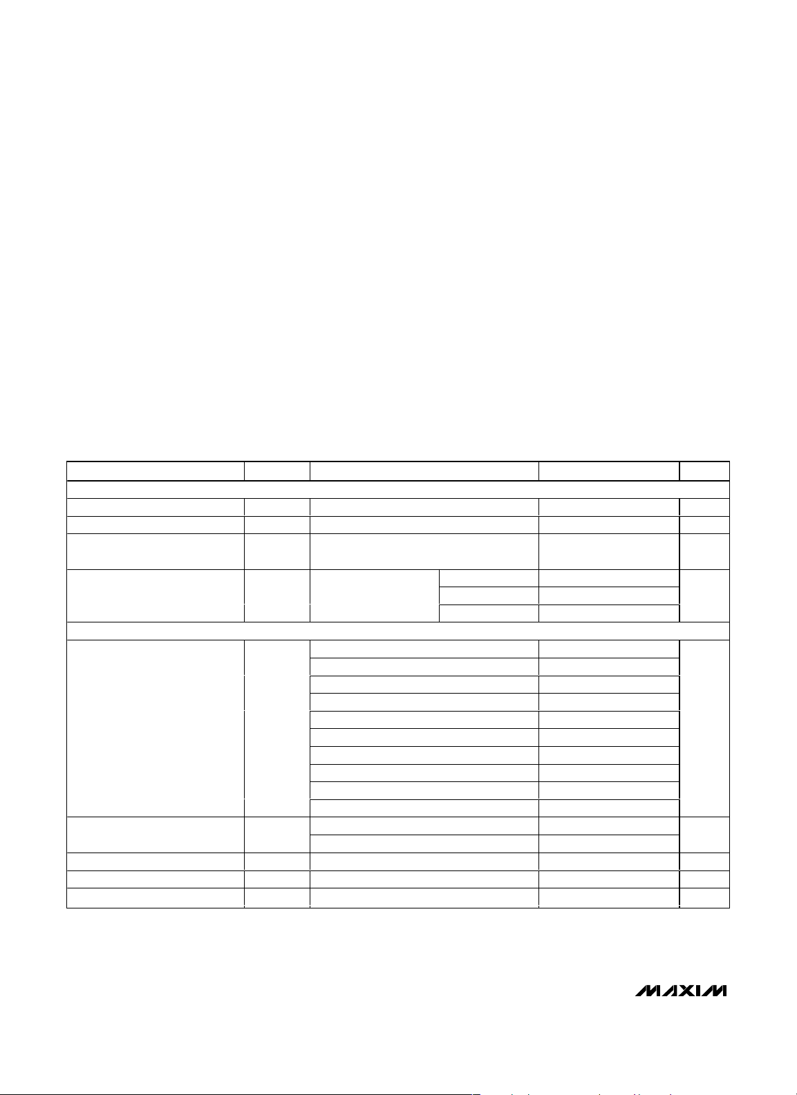
AABBSSOOLLUUTTEE MMAAXXIIMMUUMM RRAATTIINNGGSS
ELECTRICAL CHARACTERISTICS
(VCC= 2.2V to 28V, TA= -40°C to +125°C, unless otherwise specified. Typical values are at VCC= 3.3V and TA = +25°C.) (Note 1)
Stresses beyond those listed under “Absolute Maximum Ratings” may cause permanent damage to the device. These are stress ratings only, and functional
operation of the device at these or any other conditions beyond those indicated in the operational sections of the specifications is not implied. Exposure to
absolute maximum rating conditions for extended periods may affect device reliability.
(All voltages referenced to GND.)
V
CC
.........................................................................-0.3V to +30V
EN1–EN4 ....................................................-0.3V to (V
CC
+ 0.3V)
OUT1–OUT4 (push-pull).............................-0.3V to (V
CC
+ 0.3V)
OUT1–OUT4 (open-drain) ......................................-0.3V to +30V
RESET (push-pull) ......................................-0.3V to (V
CC
+ 0.3V)
RESET (open-drain) ..................................................-0.3V to 30V
IN1–IN4.......................................................-0.3V to (V
CC
+ 0.3V)
MR, TOL, TH1, TH0 ....................................-0.3V to (V
CC
+ 0.3V)
CDLY1–CDLY4 .........................................................-0.3V to +6V
CRESET......................................................-0.3V to (V
CC
+ 0.3V)
Input/Output Current (all pins)..........................................±20mA
Continuous Power Dissipation (T
A
= +70°C)
16-Pin TQFN (derate 25mW/°C above +70°C) ...........2000mW
20-Pin TQFN (derate 25.6mW/°C above +70°C) ........2051mW
24-Pin TQFN (derate 27.8mW/°C above +70°C) ........2222mW
Operating Temperature Range .........................-40°C to +125°C
Storage Temperature Range .............................-65°C to +150°C
Junction Temperature......................................................+150°C
Lead Temperature (soldering, 10s) .................................+300°C
SUPPLY
Operating Voltage Range V
Undervoltage Lockout UVLO (Note 2) 1.8 1.9 2.0 V
Undervoltage-Lockout Hysteresis UVLO
VCC Supply Current I
INPUTS (IN_)
IN_ Thresholds (IN_ Falling) V
Adjustable Threshold (IN_
Falling)
IN_ Hysteresis (IN_ Rising) V
IN_ Input Resistance Fixed threshold 500 918 kΩ
IN_ Input Current I
PARAMETER SYMBOL CONDITIONS MIN TYP MAX UNITS
(Note 2) 2.2 28.0 V
CC
HYSTVCC
CC
TH
V
TH
HYST
L
falling 50 mV
All OUT_ and RESET at
logic-high (IN_ current
excluded)
3.3V threshold, TOL = GND 2.970 3.052 3.135
3.3V threshold, TOL = V
2.5V threshold, TOL = GND 2.250 2.313 2.375
2.5V threshold, TOL = V
1.8V threshold, TOL = GND 1.620 1.665 1.710
1.8V threshold, TOL = V
1.5V threshold, TOL = GND 1.350 1.387 1.425
1.5V threshold, TOL = V
1.2V threshold, TOL = GND 1.080 1.110 1.140
1.2V threshold, TOL = V
TOL = GND 0.492 0.5 0.508
TOL = V
CC
Adjustable threshold only (V
VCC = 3.3V 40 75
VCC = 12V 47 75
V
= 28V 52 80
CC
CC
CC
CC
CC
CC
= 1V) -100 +100 nA
IN_
2.805 2.888 2.970
2.125 2.187 2.250
1.530 1.575 1.620
1.275 1.312 1.350
1.020 1.050 1.080
0.463 0.472 0.481
0.5 %
µA
V
V
Page 3

MAX16025–MAX16030
Dual-/Triple-/Quad-Voltage, Capacitor-
Adjustable, Sequencing/Supervisory Circuits
______________________________________________________________________________________________________________________________________________________________________________
3
ELECTRICAL CHARACTERISTICS (continued)
(VCC= 2.2V to 28V, TA= -40°C to +125°C, unless otherwise specified. Typical values are at VCC= 3.3V and TA = +25°C.) (Note 1)
Note 1: Devices are production tested at TA = +25°C. Limits over temperature are guaranteed by design.
Note 2: Operating below the UVLO causes all outputs to go low. The outputs are guaranteed to be in the correct state for V
CC
down
to 1.2V.
Note 3: In order to guarantee an assertion, the minimum input pulse width must be greater than 2µs.
CRESET AND CDLY_
CRESET Threshold V
CRESET Charge Current I
CDLY_ Threshold V
CDLY_ Charge Current I
DIGITAL LOGIC INPUTS (EN_, MR, TOL, TH1, TH0)
Input Low Voltage V
Input High Voltage V
TH1, TH0 Logic-Input Floating 0.6 V
TOL, TH1, TH0 Logic-Input
Current
EN_ Input Leakage Current V
MR Internal Pullup Current VCC = 3.3V 250 535 820 nA
OUTPUTS (OUT_, RESET)
Output Low Voltage (Open-Drain
or Push-Pull)
Output High Voltage (Push-Pull) V
Output Leakage Current (OpenDrain)
Reset Timeout Period t
TIMING
IN_ to OUT_ Propagation Delay
IN_ to RESET Propagation Delay t
PARAMETER SYMBOL CONDITIONS MIN TYP MAX UNITS
TH-RESET
CH-RESETVCC
TH-CDLY
CH-CDLYVCC
V
OH
I
LKG
RP
t
DELAY+
t
DELAY-
RST-DELAY
CRESET rising, VCC = 3.3V 0.465 0.5 0.535 V
= 3.3V 380 500 620 nA
CDLY_ rising, VCC = 3.3V 0.95 1 1.05 V
= 3.3V 200 250 300 nA
IL
IH
V
, V
, V
TOL
TH1
= VCC or GND -100 +100 nA
EN_
VCC ≥ 1.2V, I
VCC ≥ 2.25V, I
OL
VCC ≥ 4.5V, I
VCC ≥ 3V, I
VCC ≥ 4.5V, I
Output not asserted low, V
CRESET = VCC, VCC = 3.3V 140 190 260
CRESET open 0.030
IN_ rising, CDLY_ open 35
IN_ falling, CDLY_ open 20
CRESET open, IN_ falling 35 µs
= GND or V
TH0
= 90µA 0.3
SINK
= 0.5mA 0.3
SINK
= 1mA 0.35
SINK
= 500µA 0.8 x V
SOURCE
= 800µA 0.8 x V
SOURCE
CC
= 28V 1 µA
OUT
1.4 V
-1 +1 µA
CC
CC
0.4 V
V
V
ms
µs
MR Minimum Input Pulse Width (Note 3) 2 µs
EN_ or MR Glitch Rejection 280 ns
t
OFF
EN_ to OUT_ Delay
MR to RESET Delay MR falling 3 µs
t
ON
From device enabled to device disabled 3
From device disabled to device enabled
(CDLY_ open)
30
µs
Page 4
MAX16025–MAX16030
Dual-/Triple-/Quad-Voltage, CapacitorAdjustable, Sequencing/Supervisory Circuits
4
______________________________________________________________________________________________________________________________________________________________________________
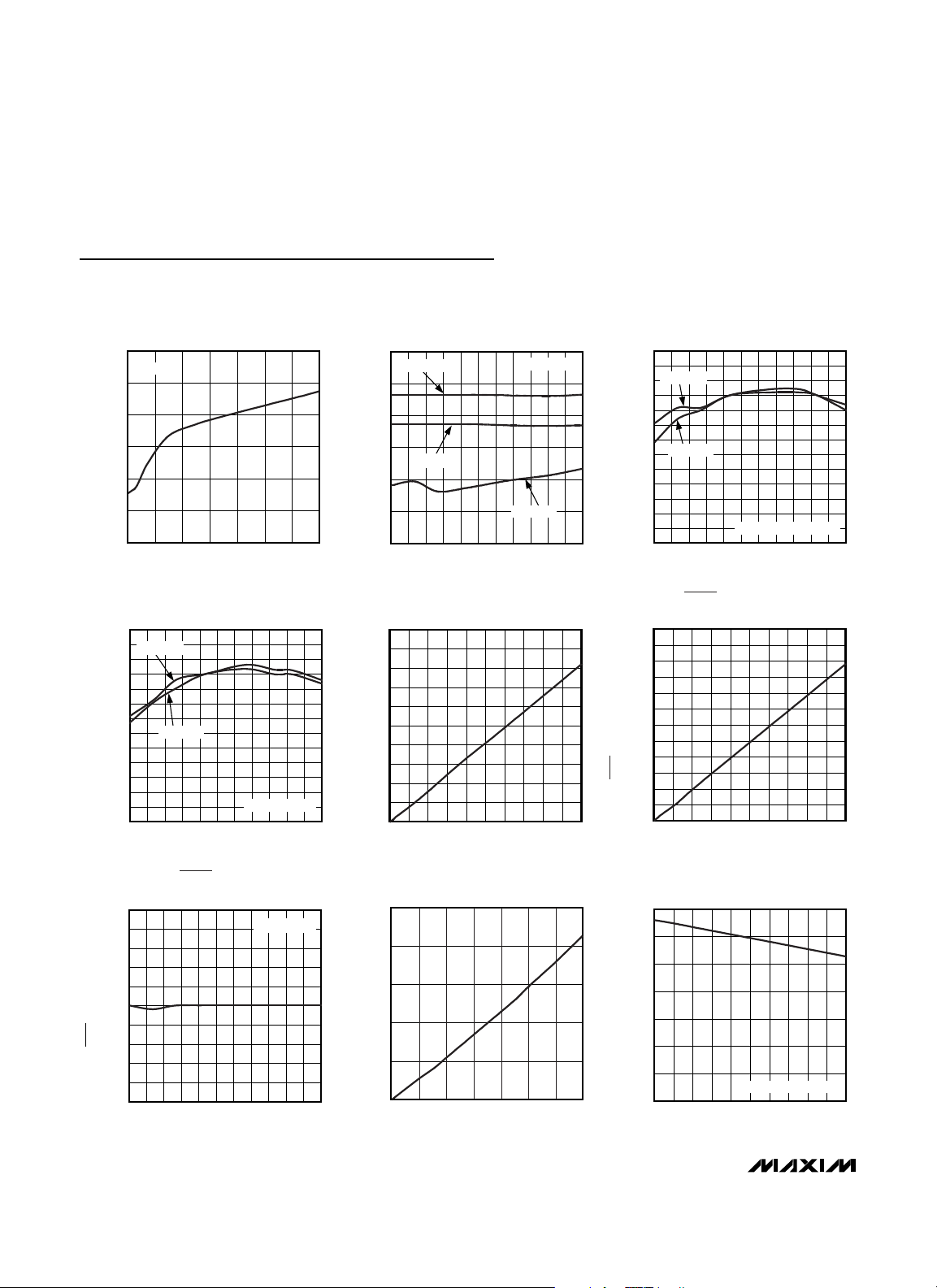
Typical Operating Characteristics
(VCC= 3.3V, TA= +25°C, unless otherwise noted.)
SUPPLY CURRENT
vs. SUPPLY VOLTAGE
MAX16025 toc01
SUPPLY VOLTAGE (V)
SUPPLY CURRENT (µA)
26221814106
35
40
45
50
55
60
30
230
MAX16026
SUPPLY CURRENT
vs. TEMPERATURE
MAX16025 toc02
TEMPERATURE (°C)
SUPPLY CURRENT (µA)
1109580655035205-10-25
35
40
45
50
55
60
30
-40 125
MAX16026
VCC = 28V
VCC = 12V
VCC = 3.3V
NORMALIZED ADJUSTABLE THRESHOLD
vs. TEMPERATURE
MAX16025 toc03
TEMPERATURE (°C)
NORMALIZED THRESHOLD
1109565 80-10 5 20 35 50-25
0.991
0.992
0.993
0.994
0.995
0.996
0.997
0.998
0.999
1.000
1.001
1.002
1.003
0.990
-40 125
TOL = VCC
TOL = GND
ADJUSTABLE THRESHOLD
NORMALIZED ADJUSTABLE THRESHOLD
vs. TEMPERATURE
MAX16025 toc04
TEMPERATURE (°C)
NORMALIZED THRESHOLD
1109565 80-10 5 20 35 50-25
0.991
0.992
0.993
0.994
0.995
0.996
0.997
0.998
0.999
1.000
1.001
1.002
1.003
0.990
-40 125
TOL = VCC
TOL = GND
3.3V THRESHOLD
OUT_ DELAY vs. C
CDLY_
MAX16025 toc05
C
CDLY_
(nF)
OUT_ DELAY (ms)
900800600 700200 300 400 500100
500
1000
1500
2000
2500
3000
3500
4000
4500
5000
0
0 1000
RESET TIMEOUT PERIOD
vs. C
CRESET
MAX16025 toc06
C
CRESET
(nF)
RESET TIMEOUT PERIOD (ms)
900800600 700200 300 400 500100
100
200
300
400
500
600
700
800
900
1000
1100
1200
0
0 1000
FIXED RESET TIMEOUT PERIOD
vs. TEMPERATURE
MAX16025 toc07
TEMPERATURE (°C)
FIXED RESET TIMEOUT PERIOD (ms)
1109565 80-10 5 20 35 50-25
181
182
183
184
185
186
187
188
189
190
180
-40 125
CRESET = VCC
OUT_ LOW VOLTAGE
vs. SINK CURRENT
MAX16025 toc08
SINK CURRENT (mA)
V
OUT_
(V)
6
5
4321
0.2
0.4
0.6
0.8
1.0
0
07
OUT_ HIGH VOLTAGE
vs. SOURCE CURRENT
MAX16025 toc09
SOURCE CURRENT (mA)
V
OUT_
(V)
0.90.80.70.60.50.40.30.20.1
0.5
1.0
1.5
2.0
2.5
3.0
3.5
0
0 1.0
PUSH-PULL VERSIONS
Page 5
MAX16025–MAX16030
Dual-/Triple-/Quad-Voltage, Capacitor-
Adjustable, Sequencing/Supervisory Circuits
_______________________________________________________________________________________
5
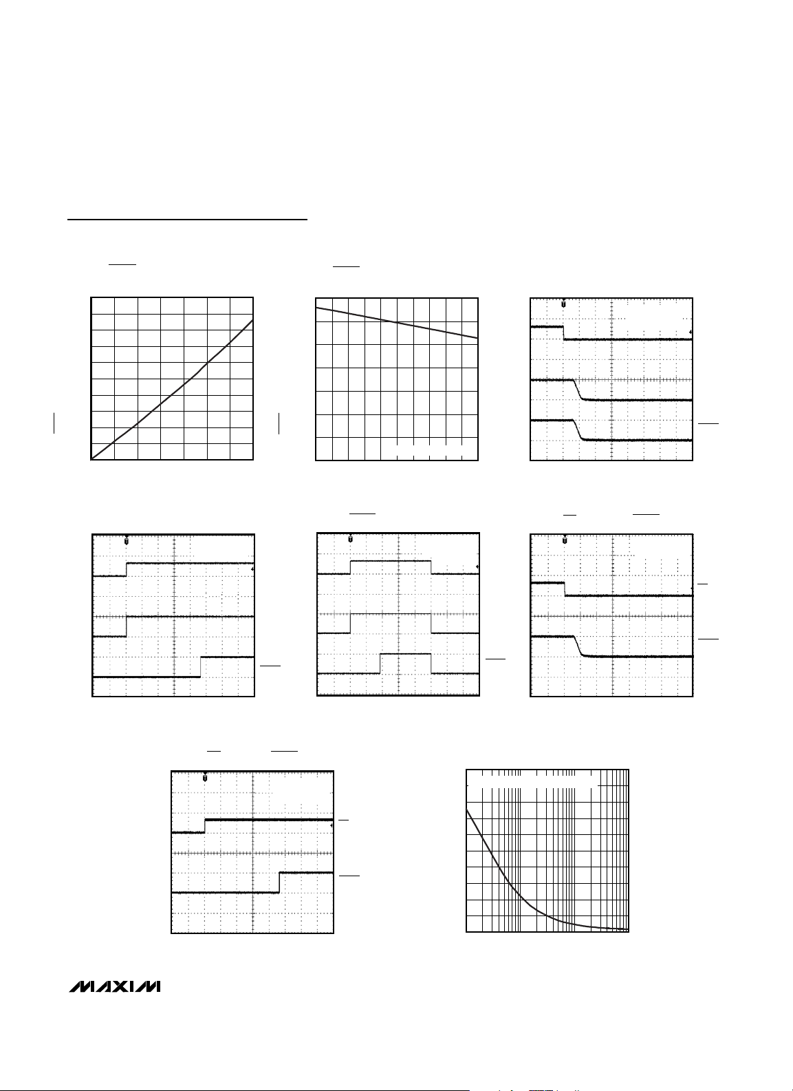
Typical Operating Characteristics (continued)
(VCC= 3.3V, TA= +25°C, unless otherwise noted.)
RESET OUTPUT LOW VOLTAGE (V)
RESET OUTPUT LOW VOLTAGE
vs. SINK CURRENT
1.0
0.9
0.8
0.7
0.6
0.5
0.4
0.3
0.2
0.1
0
07
SINK CURRENT (mA)
ENABLE TURN-ON
CRESET = V
CDLY_ = OPEN
MAX16025 toc13
MAX16025 toc10
RESET OUTPUT HIGH VOLTAGE (V)
653 421
CC
EN_
OUT_
RESET
RESET OUTPUT HIGH VOLTAGE
3.5
3.0
2.5
2.0
1.5
1.0
0.5
0
0 1.0
RESET TIMEOUT DELAY
vs. SOURCE CURRENT
PUSH-PULL VERSIONS
SOURCE CURRENT (mA)
CRESET = V
CDLY_ = OPEN
0.90.80.70.60.50.40.30.20.1
MAX16025 toc14
CC
MAX16025 toc11
IN_
OUT_
RESET
ENABLE TURN-OFF
CRESET = V
CDLY_ = OPEN
4µs/div
MR FALLING vs. RESET
CRESET = V
CDLY_ = OPEN
MAX16025 toc12
CC
EN_
OUT_
RESET
MAX16025 toc15
CC
MR
RESET
40ms/div
100ms/div
4µs/div
MAXIMUM TRANSIENT DURATION
MR RISING vs. RESET
CRESET = V
CDLY_ = OPEN
40ms/div
MAX16025 toc16
CC
100
MR
RESET
MAXIMUM TRANSIENT DURATION (µs)
vs. THRESHOLD OVERDRIVE
OUTPUT ASSERTED ABOVE THIS LINE
90
80
70
60
50
40
30
20
10
0
1 1000
THRESHOLD OVERDRIVE (mV)
10010
MAX16025 toc17
Page 6

MAX16025–MAX16030
Dual-/Triple-/Quad-Voltage, CapacitorAdjustable, Sequencing/Supervisory Circuits
6
______________________________________________________________________________________________________________________________________________________________________________
Pin Description
PIN
MAX16025/
MAX16026
111V
2 2 2 IN1
3 3 3 IN2
— 4 4 IN3
— — 5 IN4
4 5 6 TOL
5 6 7 GND Ground
6 7 8 EN1
7 8 9 EN2
— 9 10 EN3
— — 11 EN4
8 10 12 TH1
9 11 13 TH0
— — 14 OUT4
— 12 15 OUT3
10 13 16 OUT2
MAX16027/
MAX16028
MAX16029/
MAX16030
NAME FUNCTION
Supply Voltage Input. Connect a 2.2V to 28V supply voltage to power the
device. All outputs are low when V
CC
bypass V
Monitored Input 1. When the voltage at IN1 exceeds its threshold, OUT1 goes
high after the capacitor-adjustable delay period. When the voltage at IN1 falls
below its threshold, OUT1 goes low after a propagation delay.
Monitored Input 2. When the voltage at IN2 exceeds its threshold, OUT2 goes
high after the capacitor-adjustable delay period. When the voltage at IN2 falls
below its threshold, OUT2 goes low after a propagation delay.
Monitored Input 3. When the voltage at IN3 exceeds its threshold, OUT3 goes
high after the capacitor-adjustable delay period. When the voltage at IN3 falls
below its threshold, OUT3 goes low after a propagation delay.
Monitored Input 4. When the voltage at IN4 exceeds its threshold, OUT4 goes
high after the capacitor-adjustable delay period. When the voltage at IN4 falls
below its threshold, OUT4 goes low after a propagation delay.
Threshold Tolerance Input. Connect TOL to GND to select thresholds 5%
below nominal. Connect TOL to V
Active-High Logic-Enable Input 1. Driving EN1 low causes OUT1 to go low
regardless of the input voltage. Drive EN1 high to enable the monitoring
comparator.
Active-High Logic-Enable Input 2. Driving EN2 low causes OUT2 to go low
regardless of the input voltage. Drive EN2 high to enable the monitoring
comparator.
Active-High Logic-Enable Input 3. Driving EN3 low causes OUT3 to go low
regardless of the input voltage. Drive EN3 high to enable the monitoring
comparator.
Active-High Logic-Enable Input 4. Driving EN4 low causes OUT4 to go low
regardless of the input voltage. Drive EN4 high to enable the monitoring
comparator.
Threshold Select Input 1. Connect TH1 to V
select the input-voltage threshold option in conjunction with TH0 (see Table 2).
Threshold Select Input 0. Connect TH0 to V
select the input-voltage threshold option in conjunction with TH1 (see Table 2).
Output 4. When the voltage at IN4 is below its threshold or EN4 goes low,
OUT4 goes low.
Output 3. When the voltage at IN3 is below its threshold or EN3 goes low,
OUT3 goes low.
Output 2. When the voltage at IN2 is below its threshold or EN2 goes low,
OUT2 goes low.
to GND with a 0.1µF capacitor.
CC
CC
CC
is below the UVLO. For noisy systems,
to select thresholds 10% below nominal.
or GND, or leave it open to
CC
or GND, or leave it open to
CC
Page 7

MAX16025–MAX16030
Dual-/Triple-/Quad-Voltage, Capacitor-
Adjustable, Sequencing/Supervisory Circuits
______________________________________________________________________________________________________________________________________________________________________________
7
Pin Description (continued)
Table 1. Output State*
Table 2. Input-Voltage Threshold Selector
*
When VCCfalls below the UVLO, all outputs go low regardless
of the state of EN_ and V
IN_
. The outputs are guaranteed to be
in the correct state for V
CC
down to 1.2V.
PIN
MAX16025/
MAX16026
11 14 17 OUT1
12 15 18 RESET
13 16 19 MR
14 17 20 CRESET
— — 21 CDLY4
— 18 22 CDLY3
15 19 23 CDLY2
16 20 24 CDLY1
———EP
MAX16027/
MAX16028
MAX16029/
MAX16030
NAME FUNCTION
Output 1. When the voltage at IN1 is below its threshold or EN1 goes low,
OUT1 goes low.
Active-Low Reset Output. RESET asserts low when any of the monitored
voltages (IN_) falls below its respective threshold, any EN_ goes low, or MR is
asserted. RESET remains asserted for the reset timeout period after all of the
monitored voltages exceed their respective threshold, all EN_ are high, all
OUT_ are high, and MR is deasserted.
Active-Low Manual Reset Input. Pull MR low to assert RESET low. RESET
remains low for the reset timeout period after MR is deasserted (as long as all
OUT_ are high).
Capacitor-Adjustable Reset Delay Input. Connect an external capacitor from
CRESET to GND to set the reset timeout period or connect to V
default 140ms minimum reset timeout period. Leave CRESET open for internal
propagation delay.
Capacitor-Adjustable Delay Input 4. Connect an external capacitor from
CDLY4 to GND to set the IN4 to OUT4 (and EN4 to OUT4) delay period.
Leave CDLY4 open for internal propagation delay.
Capacitor-Adjustable Delay Input 3. Connect an external capacitor from
CDLY3 to GND to set the IN3 to OUT3 (and EN3 to OUT3) delay period.
Leave CDLY3 open for internal propagation delay.
Capacitor-Adjustable Delay Input 2. Connect an external capacitor from
CDLY2 to GND to set the IN2 to OUT2 (and EN2 to OUT2) delay period.
Leave CDLY2 open for internal propagation delay.
Capacitor-Adjustable Delay Input 1. Connect an external capacitor from
CDLY1 to GND to set the IN1 to OUT1 (and EN1 to OUT1) delay period.
Leave CDLY1 open for internal propagation delay.
Exposed Pad. EP is internally connected to GND. Connect EP to the
ground plane.
CC
for the
EN_ IN_ OUT_
Low V
High V
Low V
High V
< V
IN_
< V
IN_
> V
IN_
> V
IN_
Low
TH
Low
TH
Low
TH
OUT_ = high
(MAX16026/MAX16028/
MAX16030)
TH
OUT_ = high impedance
(MAX16025/MAX16027/
MAX16029)
TH1/TH0
LOGIC
Low/Low 3.3 2.5 1.8 1.5
Low/High 3.3 1.8 Adj Adj
Low/Open 3.3 1.5 Adj Adj
High/Low 3.3 1.2 1.8 2.5
High/High 2.5 1.8 Adj Adj
High/Open 3.3 Adj 2.5 Adj
Open/Low 3.3 Adj Adj Adj
Open/High 2.5 Adj Adj Adj
Open/Open Adj Adj Adj Adj
IN1 (ALL
VERSIONS)
(V)
IN2 (ALL
VERSIONS)
(V)
IN3
(MAX16027/
MAX16028)
(V)
IN4
(MAX16029/
MAX16030)
(V)
Page 8

MAX16025–MAX16030
Dual-/Triple-/Quad-Voltage, CapacitorAdjustable, Sequencing/Supervisory Circuits
8
______________________________________________________________________________________________________________________________________________________________________________
Figure 1. MAX16029/MAX16030 Simplified Functional Diagram
EN1EN2EN3EN4TH1TH0
THRESHOLD
SELECT
IN1
IN2
LOGIC
LOGIC
DELAY
IN3
DELAY
DELAY
1V
250nA
MAX16029
MAX16030
DRIVER
DRIVER
DRIVER
OUT1
OUT2
OUT3
IN4
DELAY
GND
RESET
DELAY
TOL
REFERENCE
V
CC
CDLY1 CDLY2 CDLY3 CDLY4
LOGIC
CRESET MR
DRIVER
DRIVER
OUT4
RESET
Page 9

MAX16025–MAX16030
Dual-/Triple-/Quad-Voltage, Capacitor-
Adjustable, Sequencing/Supervisory Circuits
______________________________________________________________________________________________________________________________________________________________________________
9
Detailed Description
The MAX16025–MAX16030 are low-voltage, accurate,
dual-/triple-/quad-voltage microprocessor (µP) supervisors in a small TQFN package. These devices provide
supervisory and sequencing functions for complex multivoltage systems. The MAX16025/MAX16026 monitor
two voltages, the MAX16027/MAX16028 monitor three
voltages, and the MAX16029/MAX16030 monitor four
voltages.
The MAX16025–MAX16030 offer independent outputs
and enable functions for each monitored voltage. This
configuration allows the device to operate as four separate supervisory circuits or be daisy-chained together to
allow controlled sequencing of power supplies during
power-up initialization. When all of the monitored voltages exceed their respective thresholds, an independent reset output deasserts to allow the system
processor to operate.
These devices offer enormous flexibility as there are
nine threshold options that are selected through two
threshold-select logic inputs. Each monitor circuit also
offers an independent enable input to allow both digital
and analog control of each monitor output. A tolerance
select input allows these devices to be used in systems
requiring 5% or 10% power-supply tolerances. In addition, the time delays and reset timeout can be adjusted
using small capacitors. There is also a fixed 140ms
minimum reset timeout feature.
Figure 2. Timing Diagram (CDLY_ Open)
V
IN_
EN_
OUT_
RESET
CC
V
UVLO
V
TH
t
t
ON
t
RP
DELAY-
t
RST_DELAY
V
t
DELAY+
TH
t
RP
t < t
ON
t
ON
t
OFF
t
RP
Page 10

MAX16025–MAX16030
Applications Information
Tolerance
The MAX16025–MAX16030 feature a pin-selectable
threshold tolerance. Connect TOL to GND to select the
thresholds 5% below the nominal value. Connect TOL to
VCCto select the threshold tolerance 10% below the
nominal voltage. Do not leave TOL unconnected.
Adjustable Input
These devices offer several monitoring options with
both fixed and/or adjustable reset thresholds (see
Table 2). For the adjustable threshold inputs, the
threshold voltage (VTH) at each adjustable IN_ input is
typically 0.5V (TOL = GND) or 0.472V (TOL = VCC). To
monitor a voltage V
INTH
, connect a resistive divider network to the circuit as shown in Figure 3 and use the following equation to calculate the threshold voltage:
Choosing the proper external resistors is a balance
between accuracy and power use. The input to the voltage monitor is a high-impedance input with a small
100nA leakage current. This leakage current contributes to the overall error of the threshold voltage
where the output is asserted. This induced error is proportional to the value of the resistors used to set the
threshold. With lower value resistors, this error is
reduced, but the amount of power consumed in the
resistors increases.
The following equation is provided to help estimate the
value of the resistors based on the amount of acceptable error:
where e
A
is the fraction of the maximum acceptable
absolute resistive divider error attributable to the input
leakage current (use 0.01 for ±1%), V
INTH
is the voltage at which the output (OUT_) should assert, and ILis
the worst-case IN_ leakage current (see the
Electrical
Characteristics
). Calculate R2 as follows:
Unused Inputs
Connect any unused IN_ and EN_ inputs to VCC.
OUT_ Output
An OUT_ goes low when its respective IN_ input voltage
drops below its specified threshold or when its EN_ goes
low (see Table 1). OUT_ goes high when EN_ is high and
V
IN_
is above its threshold after a time delay. The
MAX16025/MAX16027/MAX16029 feature open-drain,
outputs while the MAX16026/MAX16028/MAX16030
have push-pull outputs. Open-drain outputs require an
external pullup resistor to any voltage from 0 to 28V.
RESET
Output
RESET asserts low when any of the monitored voltages
(IN_) falls below its respective threshold, any EN_ goes
low, or MR is asserted. RESET remains asserted for the
reset timeout period after all of the monitored voltages
exceed their respective threshold, all EN_ are high, all
OUT_ are high, and MR is deasserted. The MAX16025/
MAX16027/MAX16029 have an open-drain, active-low
reset output, while the MAX16026/MAX16028/
MAX16030 have a push-pull, active-low reset output.
Open-drain RESET requires an external pullup resistor to
any voltage from 0 to 28V.
Adjustable Reset Timeout Period
(CRESET)
All of these parts offer an internally fixed reset timeout
(140ms min) by connecting CRESET to VCC. The reset
timeout can also be adjusted by connecting a capacitor from CRESET to GND. When the voltage at CRESET
reaches 0.5V, RESET goes high. When RESET goes
high, CRESET is immediately held low.
Dual-/Triple-/Quad-Voltage, CapacitorAdjustable, Sequencing/Supervisory Circuits
10
____________________________________________________________________________________________________________________________________________________________________________
Figure 3. Setting the Adjustable Input
R
1
⎛
VV
=×+
INTH TH
⎞
1
⎜
⎟
⎝
⎠
R
2
V
INTH
R1
IN_
R2
V
TH
MAX16025–
MAX16030
V
R1 = R2 x (
INTH
V
TH
-1
)
eV
R
AINTH
=
1
×
I
L
R
2
VV
INTH TH
1=×
VR
TH
−
Page 11

Calculate the reset timeout period as follows:
where V
TH-RESET
is 0.5V, I
CH-RESET
is 0.5µA, tRPis in
seconds, and C
CRESET
is in Farads. To ensure timing
accuracy and proper operation, minimize leakage at
C
CRESET
.
Adjustable Delay (CDLY_)
When VINrises above VTHwith EN_ high, the internal
250nA current source begins charging an external
capacitor connected from CDLY_ to GND. When the
voltage at CDLY_ reaches 1V, OUT_ goes high. When
OUT_ goes high, CDLY_ is immediately held low.
Adjust the delay (t
DELAY
) from when VINrises above
VTH(with EN_ high) to OUT_ going high according to
the equation:
where V
TH-CDLY
is 1V, I
CH-CDLY
is 0.25µA, C
CDLY
is in
Farads, t
DELAY
is in seconds, and t
DELAY+
is the internal propagation delay of the device. To ensure timing
accuracy and proper operation, minimize leakage
at CDLY.
Manual-Reset Input (MR)
Many µP-based products require manual-reset capability, allowing the operator, a test technician, or external
logic circuitry to initiate a reset. A logic-low on MR
asserts RESET low. RESET remains asserted while MR
is low and during the reset timeout period (140ms fixed
or capacitor adjustable) after MR returns high. The MR
input has a 500nA internal pullup, so it can be left
unconnected, if not used. MR can be driven with TTL or
CMOS logic levels, or with open-drain/collector outputs.
Connect a normally open momentary switch from MR to
GND to create a manual-reset function. External
debounce circuitry is not required. If MR is driven from
long cables or if the device is used in a noisy environment, connect a 0.1µF capacitor from MR to GND to
provide additional noise immunity.
Pullup Resistor Values
The exact value of the pullup resistors for the opendrain outputs is not critical, but some consideration
should be made to ensure the proper logic levels
when the device is sinking current. For example, if
VCC= 2.25V and the pullup voltage is 28V, keep the
sink current less than 0.5mA as shown in the
Electrical
Characteristics
table. As a result, the pullup resistor
should be greater than 56kΩ. For a 12V pullup, the
resistor should be larger than 24kΩ. Note that the ability
to sink current is dependent on the VCCsupply voltage.
Power-Supply Bypassing
The device operates with a VCCsupply voltage from
2.2V to 28V. When VCCfalls below the UVLO threshold,
all the outputs go low and stay low until VCCfalls below
1.2V. For noisy systems or fast rising transients on VCC,
connect a 0.1µF ceramic capacitor from VCCto GND
as close to the device as possible to provide better
noise and transient immunity.
Ensuring Valid Output with VCCDown to
0V (MAX16026/MAX16028/MAX16030 Only)
When VCCfalls below 1.2V, the ability for the output to
sink current decreases. In order to ensure a valid output as VCCfalls to 0V, connect a 100kΩ resistor from
OUT/RESET to GND.
Typical Application Circuits
Figures 4 and 5 show typical applications for the
MAX16025–MAX16030. In high-power applications,
using an n-channel device reduces the loss across the
MOSFETs as it offers a lower drain-to-source on-resistance. However, an n-channel MOSFET requires a sufficient VGSvoltage to fully enhance it for a low R
DS_ON
.
The application in Figure 4 shows the MAX16027 configured in a multiple-output sequencing application.
Figure 5 shows the MAX16029 in a power-supply
sequencing application using n-channel MOSFETs.
MAX16025–MAX16030
Dual-/Triple-/Quad-Voltage, Capacitor-
Adjustable, Sequencing/Supervisory Circuits
____________________________________________________________________________________________________________________________________________________________________________
11
V
t
=×+×
RP
I
CH RESET
TH RESET
−
−
C
CRESET
30 10
−
6
t
DELAY
V
TH CDLY
−
=×+×
I
−
CH CDLY
C
CDLY
35 10
−
6
Page 12

MAX16025–MAX16030
Dual-/Triple-/Quad-Voltage, CapacitorAdjustable, Sequencing/Supervisory Circuits
12
____________________________________________________________________________________________________________________________________________________________________________
Figure 4. Sequencing Multiple-Voltage System
Figure 5. Multiple-Voltage Sequencing Using n-Channel FETs
+12V BUS
+3.3V
DC-DC OUT
IN
V
CC
MR
DC-DC OUT
EN
EN1
CDLY1
IN1
CDLY2
IN
EN
OUT1 EN2
CDLY3 CRESET
12V
BUS
1.5V
MAX16027
IN2
+2.5V
GND
TOL TH0 TH1
IN
DC-DC OUT
EN
OUT2 EN3
IN3
+1.8V
OUT3
RESET
+3.3V
SYSTEM
RESET
1.8V
2.5V
3.3V
V
EN1
EN2
EN3
EN4
CC
CDLY1
IN1
CDLY2
IN2OUT1
CDLY3 CDLY4
OUT2
MAX16029
CRESET
IN3 OUT3
GND
TOL TH0 TH1
IN4
OUT4
RESET
MR
TO
LOADS
+3.3V
SYSTEM
RESET
Page 13

MAX16025–MAX16030
Dual-/Triple-/Quad-Voltage, Capacitor-
Adjustable, Sequencing/Supervisory Circuits
____________________________________________________________________________________________________________________________________________________________________________
13
Pin Configurations (continued)
Chip Information
PROCESS: BICMOS
TRANSISTOR COUNT: 3642
TOP VIEW
CRESET
MR
CDLY2
CDLY1
12 11 9
13
14
15
16
+
12
OUT1
RESET
10
MAX16025
MAX16026
3
CC
IN1
V
IN2 OUT2
THIN QFN
(4mm x 4mm)
TH0
MR
CRESET
CDLY3
CDLY2
CDLY1
16
17
18
19
20
+
TH1
8
7
EN2
EN1
6
GND
5
4
TOL
OUT1
RESET
15 14 12 11
OUT3
OUT2
13
MAX16027
MAX16028
12
CC
IN1
V
3
IN2
45
IN3
TH0
TOL
TH1
10
EN3
9
8
EN2
EN1
7
GND
6
THIN QFN
(4mm x 4mm)
Page 14

MAX16025–MAX16030
Dual-/Triple-/Quad-Voltage, CapacitorAdjustable, Sequencing/Supervisory Circuits
14
____________________________________________________________________________________________________________________________________________________________________________
Package Information
(The package drawing(s) in this data sheet may not reflect the most current specifications. For the latest package outline information
go to www.maxim-ic.com/packages
.)
24L QFN THIN.EPS
PACKAGE OUTLINE,
12, 16, 20, 24, 28L THIN QFN, 4x4x0.8mm
21-0139
1
E
2
Page 15

MAX16025–MAX16030
Dual-/Triple-/Quad-Voltage, Capacitor-
Adjustable, Sequencing/Supervisory Circuits
Maxim cannot assume responsibility for use of any circuitry other than circuitry entirely embodied in a Maxim product. No circuit patent licenses are
implied. Maxim reserves the right to change the circuitry and specifications without notice at any time.
Maxim Integrated Products, 120 San Gabriel Drive, Sunnyvale, CA 94086 408-737-7600 ____________________
15
© 2006 Maxim Integrated Products is a registered trademark of Maxim Integrated Products, Inc.
Package Information (continued)
(The package drawing(s) in this data sheet may not reflect the most current specifications. For the latest package outline information
go to www.maxim-ic.com/packages
.)
Revision History
Pages changed at Rev 1: 1, 3, 15
PACKAGE OUTLINE,
12, 16, 20, 24, 28L THIN QFN, 4x4x0.8mm
21-0139
2
E
2
 Loading...