

Page 1
General Description
The MAX1578/MAX1579 provide four regulated outputs
to meet all the voltage requirements for small activematrix TFT-LCD displays in handheld devices where
minimum external components and high efficiency are
required. Each device consists of three advanced
charge pumps for LCD bias power and a step-up converter for driving up to 8 series white LEDs for backlighting. The input voltage range is from 2.7V to 5.5V.
The charge pumps provide fixed +5V, +15V, and -10V
for the LCD bias circuits. No external diodes are needed. A high-efficiency, fractional (1.5x/2x) charge pump
followed by a low-dropout linear regulator provides +5V
to power the source driver. Automatic mode changing
achieves the highest conversion efficiency. Two multistage, high-voltage charge pumps generate +15V and
-10V to provide VONand V
OFF
, respectively. Utilizing a
unique clocking scheme and internal drivers, these
charge pumps eliminate parasitic charge-current glitches and reduce maximum input current, resulting in low
electromagnetic emissions. The outputs are sequenced
during startup and shutdown. In shutdown, the outputs
are discharged to zero.
The high-efficiency inductor step-up converter drives
up to 8 white LEDs in series with a constant current to
provide backlighting. The series connection allows the
LED currents to be identical for uniform brightness and
minimizes the number of traces to the LEDs. The
MAX1578 regulates constant LED current over the
entire temperature range. The MAX1579 features a temperature derating function to avoid overdriving the
white LEDs during high ambient temperatures, enabling
higher drive current below +42°C.
The MAX1578/MAX1579 are available in space-saving
24-lead 4mm x 4mm thin QFN packages.
Applications
PDAs, Palmtops
Smart Phones
Internet Appliances
LCD Displays with White LED Backlight
Features
♦ Four Regulators in One Package
♦ Bias Power Using Charge Pumps
+5V at 25mA for Source Driver
+15V at 100µA for V
ON
-10V at 100µA for V
OFF
No External Diodes Required
Output Sequencing
POS, NEG, and MAIN Are Autodischarged
During Shutdown
♦ LED Backlight Power Using Boost Converter
Series LED Connection for Uniform Illumination
Supports Up to 8 LEDs at 25mA (max)
900mW (max) Power
PWM or Analog Dimming Control
Overvoltage Protection
Low Input/Output Ripple
Soft-Start with Zero Inrush Current
Fast 1MHz PWM Operation for Small
Component Size
Temperature Derating Function (MAX1579)
♦ High Efficiency
Bias: 83% (5.0V at 25mA, 15V/-10V at 100µA)
LED: 84% (6 LEDs at 20mA)
♦ Uses Only Ceramic Capacitors and Only One
Inductor
♦ Independent Enable Inputs for LED and Bias
Power
♦ Thermal-Shutdown Protection
♦ 1µA Shutdown Current
♦ Tiny 4mm x 4mm Thin QFN Package
MAX1578/MAX1579
Complete Bias and White LED Power Supplies
for Small TFT Displays
________________________________________________________________ Maxim Integrated Products 1
19-3359; Rev 0; 8/04
For pricing delivery, and ordering information please contact Maxim/Dallas Direct! at
1-888-629-4642, or visit Maxim’s website at www.maxim-ic.com.
Ordering Information
EVALUATION KIT
AVAILABLE
PART
PIN-PACKAGE
MAX1578ETG
24 Thin QFN 4mm x 4mm
(T2444-4)
MAX1579ETG
24 Thin QFN 4mm x 4mm
(T2444-4)
MAX1578/MAX1579
See Figure 3 for Typical Application Circuit.
ONBIAS
CD2
GND
NEG
PMPB
CD1
LX
CTRL
PGND
OUT
COMP
CS
CU1
CU3
MAIN
CU2
PMP
POS
19
20
21
22
23
24
1 2 3 4 5 6
18 17 16 15 14 13
12
11
10
9
8
7
MAX1578
MAX1579
THIN QFN
4mm x 4mm
C2N
C2P
C1N
IN
V
DD
C1P
Pin Configuration
TEMP RANGE
-40°C to +85°C
-40°C to +85°C
Page 2
MAX1578/MAX1579
Complete Bias and White LED Power Supplies
for Small TFT Displays
2 _______________________________________________________________________________________
ABSOLUTE MAXIMUM RATINGS
ELECTRICAL CHARACTERISTICS
(Circuit of Figure 3, VIN= 3V, CTRL = ONBIAS = IN, TA= -40°C to +85°C, typical values are at TA= +25°C, unless otherwise noted. Note 1)
Stresses beyond those listed under “Absolute Maximum Ratings” may cause permanent damage to the device. These are stress ratings only, and functional
operation of the device at these or any other conditions beyond those indicated in the operational sections of the specifications is not implied. Exposure to
absolute maximum rating conditions for extended periods may affect device reliability.
IN, CS, C1N, C2N, MAIN, ONBIAS, VDDto GND.....-0.3V to +6V
CTRL to GND..................-0.3V to the lesser of +6V or (V
IN
+ 2V)
LX, OUT to GND.....................................................-0.3V to +37V
COMP to GND .............................................-0.3V to (V
IN
+ 0.3V)
CU1 to MAIN ............................................................-0.3V to +6V
CU2 to CU1..............................................................-0.3V to +6V
CU3 to CU2..............................................................-0.3V to +6V
CU3 to POS............................................................-0.3V to +18V
CU3 to GND ...........................................................-0.3V to +18V
POS to GND ...........................................................-0.3V to +18V
CD1 to MAIN ..........................................................+0.3V to -12V
CD1 to GND .............................................................+0.3V to -6V
CD2 to CD1..............................................................+0.3V to -6V
NEG to CD2..............................................................+0.3V to -6V
NEG, CD2 to GND..................................................+0.3V to -12V
C1P, C2P to GND ...........................................-0.3V to (V
IN
+ 6V)
PMP, PMPB to GND................................-0.3V to (V
MAIN
+ 0.3V)
GND to PGND .......................................................-0.3V to +0.3V
I
LX
...................................................................................1.0A
RMS
Continuous Power Dissipation (TA= +70°C)
24-Pin 4mm x 4mm Thin QFN
(derate 20.8mW/°C above +70°C).............................1667mW
Short-Circuit Duration (MAIN, POS, NEG)..................Continuous
Operating Temperature Range ...........................-40°C to +85°C
Junction Temperature......................................................+150°C
Storage Temperature Range.............................-65°C to +150°C
Lead Temperature (soldering, 10s)................................ +300°C
PARAMETER CONDITIONS
MIN
TYP
MAX
UNITS
IN Operating Supply Range 2.7 5.5 V
IN Undervoltage-Lockout (UVLO)
Threshold
Rising edge, 30mV hysteresis 2.1
2.6 V
IN Quiescent Current Switching 3 5 mA
TA = +25°C 0.4 1
IN Shutdown Current V
CTRL
= V
ONBIAS
= 0V
T
A
= +85°C 1
µA
Thermal Shutdown Rising temperature, 20°C hysteresis (typ)
°C
MAIN CHARGE PUMP WITH LINEAR REGULATOR
Main Pump Efficiency I
LOAD
= 25mA, VIN = 3.9V 83 %
VIN ≥ 3.8V in 1.5x mode 9 20
VDD Charge-Pump Open-Loop
Output Impedance
V
IN
≥ 3.0V in 2.0x mode 7.5 20
Ω
Operating Frequency
kHz
VDD Output Voltage Charge-pump pause threshold 5.2 5.5 5.7 V
V
IN
Fal l i ng S w i tchover to 2.0x M od e
V
V
IN
Ri si ng S w i tchover to 1.5x M od e
3.8 3.9 4.0 V
Quiescent Current
(Charge Pumps Only)
V
CTRL
= 0V, ONBIAS = IN
mA
V
MAIN
Regulation Voltage 0.1mA < I
LOAD
< 25mA 4.9 5.0 5.1 V
Discharge Switch Resistance
at V
MAIN
V
ONBIAS
= 0V 1 3 kΩ
POS, NEG CHARGE PUMPS
Operating Frequency
kHz
Duty Cycle 50 %
POS Pump Efficiency I
LOAD
= 100µA 97 %
POS Output Voltage I
LOAD
= 0 to 100µA
V
P OS D i schar g e S w i tch Resi stance
V
ONBIAS
= 0V 3 6 kΩ
NEG Pump Efficiency I
LOAD
= -100µA 97 %
2.35
200 250 300
3.75 3.85 3.95
12.0 15.6 19.5
13.9 14.7 15.3
+160
0.87 1.30
Page 3
MAX1578/MAX1579
Complete Bias and White LED Power Supplies
for Small TFT Displays
_______________________________________________________________________________________ 3
PARAMETER CONDITIONS
UNITS
NEG Output Voltage I
LOAD
= 0 to -100µA
V
N E G D i schar g e S w i tch Resi stance
V
ONBIAS
= 0V 1.5 3 kΩ
LOGIC INPUT (ONBIAS)
Logic Input Low Voltage
V
Logic Input High Voltage 1.6 V
TA = +25°C
1
Input Current
T
A
= +85°C 1
µA
LED BACKLIGHTING
Efficiency LOAD = 6 LEDs in series at 20mA 84 %
OUT Voltage Range (Note 2)
(V
IN
32 V
Overvoltage-Lockout (OVLO)
Threshold
V
OUT
rising, 2V hysteresis 32 34 36 V
V
OUT
= 32V, V
CTRL
> 0.24V 10 20 32
1
OUT Input Bias Current
V
OUT
= VIN, V
CTRL
= 0
0.1
µA
ERROR AMPLIFIER
TA = +25°C
CTRL to CS Regulation
V
CTRL
= 1.5V, VIN = 2.7V to
5.5V
T
A
= -40°C to +85°C
V
TA = +25°C
1
CS Input Bias Current VCS = V
CTRL
/ 5
T
A
= +85°C
µA
MAX1578
CTRL Input Resistance V
CTRL
< 1.0V
kΩ
CTRL Dual Mode™ Threshold 5mV hysteresis
mV
CTRL Shutdown Delay (Note 3) 6.5 8.2
ms
CS to COMP Transconductance V
COMP
= 1.0V 32 60 90 µS
CS Regulation Derating Function
Start Temperature
V
CTRL
= 3V, MAX1579 only
°C
CS Regulation Derating Function
Slope
V
CTRL
= 3V, TA = +65°C, MAX1579 only -6
mV/°C
MAX1578, V
CTRL
= 3V
CS Maximum Brightness Clamp
Voltage
MAX1579, V
CTRL
= 3V, TA = +25°C
mV
MAX1578
CS Maximum Brightness Voltage
at CTRL
MAX1579
V
OSCILLATOR
Operating Frequency f
BOOST
0.8 1.0 1.2 MHz
PWM mode 12
Minimum Duty Cycle
Pulse skipping 0
%
Maximum Duty Cycle CTRL = IN, CS = GND 92 95 %
ELECTRICAL CHARACTERISTICS (continued)
(Circuit of Figure 3, VIN= 3V, CTRL = ONBIAS = IN, TA= -40°C to +85°C, typical values are at TA= +25°C, unless otherwise noted. Note 1)
Dual Mode is a trademark of Maxim Integrated Products, Inc.
TA = +25°C 0.01
TA = +85°C
TA = +25°C 250 500 780
= +85°C 185
T
A
MAX1579
MIN TYP MAX
-10.2 -9.8 -9.3
0.01
VD1)
0.295 0.300 0.305
0.292 0.300 0.308
0.01
0.03
250 500 780
100 170 240
+42
0.72
10.5
310 327 345
322 340 358
1.635
1.70
Page 4
MAX1578/MAX1579
Complete Bias and White LED Power Supplies
for Small TFT Displays
4 _______________________________________________________________________________________
Note 1: All devices are 100% production tested at TA= +25°C. Limits over the operating temperature range are guaranteed by design.
Note 2: V
D1
is the forward-voltage drop of diode D1 in Figure 3.
Note 3: Time from CTRL going below the Dual-Mode threshold to IC shutdown.
ELECTRICAL CHARACTERISTICS (continued)
(Circuit of Figure 3, VIN= 3V, CTRL = ONBIAS = IN, TA= -40°C to +85°C, typical values are at TA= +25°C, unless otherwise noted. Note 1)
PARAMETER CONDITIONS
MIN
TYP
MAX
UNITS
N-CHANNEL SWITCH
LX On-Resistance ILX = 190mA
1.5 Ω
TA = +25°C
5
LX Leakage Current V
LX
= 28V, CTRL = GND
T
A
= +85°C 1
µA
LX Current Limit Duty cycle = 90%
mA
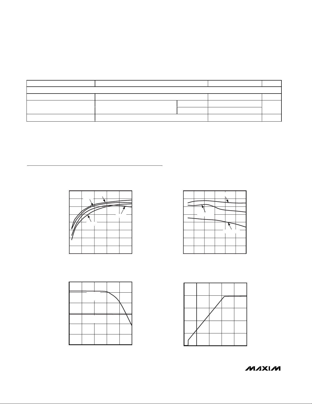
Typical Operating Characteristics
(Circuit of Figure 3, VIN= 3.6V, I
LED
= 20mA, 4 LEDs, CTRL = IN, TA= +25°C, unless otherwise noted.)
50
55
60
65
70
75
80
85
90
2.5 3.0 3.5 4.0 4.5 5.0 5.5
LED EFFICIENCY vs. V
IN
MAX1578toc02
INPUT VOLTAGE (V)
EFFICIENCY (%)
I
LED
= 2mA
I
LED
= 10mA
I
LED
= 20mA
0
10
5
20
15
25
30
-40 85
LED CURRENT vs. TEMPERATURE
MAX1578toc03
TEMPERATURE (°C)
I
LED
(mA)
10-15 35 60
MAX1579
R
CS
= 13
Ω
MAX1578
R
CS
= 22
Ω
0
5
15
10
20
25
01.00.5 1.5 2.0 2.5
LED CURRENT vs. V
CTRL
MAX1578toc04
CTRL VOLTAGE (V)
I
LED
(mA)
0.82
0.01
500 700 900
LED EFFICIENCY vs. I
90
85
80
75
70
65
EFFICIENCY (%)
60
55
50
0 5 10 15 20 25
4 LEDs
6 LEDs
2 LEDs
LED CURRENT (mA)
LED
8 LEDs
MAX1578toc01
Page 5

Typical Operating Characteristics (continued)
(Circuit of Figure 3, VIN= 3.6V, I
LED
= 20mA, 4 LEDs, CTRL = IN, TA= +25°C, unless otherwise noted.)
MAX1578/MAX1579
Complete Bias and White LED Power Supplies
for Small TFT Displays
_______________________________________________________________________________________ 5
PWM-DIMMING WAVEFORMS
MAX1578toc08
V
CTRL
I
IN
V
OUT
AC-COUPLED
V
IN
AC-COUPLED
2V/div
50mV/div
20mA/div
20mV/div
40µs/div
0
400
200
800
600
1200
1000
1400
023145
LCD BIAS SUPPLY CURRENT
vs. INPUT VOLTAGE
MAX1578toc09
INPUT VOLTAGE (V)
I
IN
(µA)
V
CTRL
= 0V
LCD BIAS STARTUP SEQUENCE
MAX1578toc10
V
ONBIAS
V
POS
V
NEG
V
MAIN
5V/div
5V/div
10V/div
5V/div
10ms/div
BOOST STARTUP AND
SHUTDOWN WAVEFORMS
MAX1578toc07
V
CTRL
I
IN
V
OUT
V
IN
AC-COUPLED
2V/div
5V/div
0V
100mA/div
20mV/div
4ms/div
0
5
10
15
20
25
0405020 3010 60 70 80 90 100
LED CURRENT vs.
DIRECT-PWM DUTY CYCLE
MAX1578toc05
PWM DUTY CYCLE (%)
I
LED
(mA)
f
PWM
= 200Hz TO 200kHz
BOOST-SWITCHING WAVEFORMS
MAX1578toc06
V
IN
AC-COUPLED
V
LX
V
OUT
AC-COUPLED
20mV/div
10V/div
200mV/div
400ns/div
Page 6

MAX1578/MAX1579
Complete Bias and White LED Power Supplies
for Small TFT Displays
6 _______________________________________________________________________________________
-5.0
-3.5
-4.0
-4.5
-3.0
-2.5
-2.0
-1.5
-1.0
POS
NEG
-0.5
0
04020 60 80 100
POS AND NEG LOAD REGULATION
MAX1578toc12
LOAD CURRENT (µA)
VOLTAGE DROOP (%)
-0.6
-0.4
-0.5
-0.2
-0.3
-0.1
0
025
MAIN OUTPUT LOAD REGULATION
MAX1578toc11
LOAD CURRENT (mA)
VOLTAGE DROOP (%)
1051520
PIN NAME FUNCTION
1 MAIN
LDO Output and the POS and NEG Charge-Pump Inputs. V
MAIN
is regulated to 5V. Bypass to GND
with a 1µF capacitor. Output is internally discharged with a 1kΩ resistor when V
ONBIAS
= 0V.
2 CU1 POS Charge-Pump Capacitor Connection 1. Connect a 1µF capacitor between CU1 and PMP.
3 CU2 POS Charge-Pump Capacitor Connection 2. Connect a 1µF capacitor between CU2 and PMPB.
4 CU3 POS Charge-Pump Capacitor Connection 3. Connect a 1µF capacitor between CU3 and GND.
5 POS
Output of Positive (3x) Charge Pump. Bypass POS to GND with a 1µF capacitor. POS is internally
discharged with a 3kΩ resistor when V
ONBIAS
= 0V.
6PMP
Charge-Pump Capacitor Connection. Connect a 1µF capacitor between PMP and CU1 and another
1µF capacitor between PMP and CD1.
7 PMPB
Charge-Pump Capacitor Connection. Connect a 1µF capacitor between PMPB and CU2 and another
1µF capacitor between PMPB and CD2. PMPB is 180° out of phase with PMP.
8 CD1
NEG Charge-Pump Capacitor Connection 1. Connect a 1µF capacitor and a 200Ω ±5% resistor in
series between CD1 and PMP.
9 CD2
NEG Charge-Pump Capacitor Connection 2. Connect a 1µF capacitor and a 200Ω ±5% resistor in
series between CD2 and PMPB.
10 NEG
Output of Inverting (-2x) Charge Pump. Bypass NEG to GND with a 1µF capacitor. Output is internally
discharged with a 1.5kΩ resistor when V
ONBIAS
= 0V.
Pin Description
Typical Operating Characteristics (continued)
(Circuit of Figure 3, VIN= 3.6V, I
LED
= 20mA, 4 LEDs, CTRL = IN, TA= +25°C, unless otherwise noted.)
Page 7

MAX1578/MAX1579
Complete Bias and White LED Power Supplies
for Small TFT Displays
_______________________________________________________________________________________ 7
PIN NAME FUNCTION
11 ONBIAS
Logic Input to Enable V
DD
, MAIN, POS, and NEG Charge Pumps. Drive ONBIAS high to enable all the
charge pumps. Connect to GND to disable the charge pumps.
12 GND Ground. Connect to PGND and the exposed pad directly under the IC.
13 COMP
LED Driver Compensation. Connect a 0.1µF from COMP to GND. C
COMP
stabilizes the driver and
sets the soft-start time.
14 CS
Current-Sense Feedback Input. Connect a resistor from CS to GND to set the LED current. For the
MAX1578, CS regulates to V
CTRL
/ 5 or 0.327V, whichever is lower. For the MAX1579, CS regulates to
V
CTRL
/ 5 or 0.340V, whichever is lower.
15 CTRL
LE D Br i g htness C ontr ol Inp ut. C onnect C TRL to a 0.24V to 1.65V i np ut to set the b r i g htness of the
exter nal LE D s. H ol d C TRL b el ow 100m V for m or e than 10.5m s, to shut d ow n the LE D d r i ver . D r i ve C TRL
w i th a 200H z t o 200kH z unfi l ter ed P W M d i m m i ng si g nal for D C LE D cur r ent that i s p r op or ti onal to the
si g nal ’ s d uty cy cl e.
16 OUT
Over vol tag e S ense Inp ut. The M AX 1578/M AX 1579 tur n off the n- channel M OS FE T w hen V
OU T
exceed s 34V .
Once V
OU T
d r op s b el ow 32V , the IC r e- enter s soft- star t. B yp ass OU T to GN D w i th a 0.1µF cap aci tor .
17 LX
Inductor Connection. Connect to the switched side of the external inductor as well as the anode of the
external diode. LX is high impedance during shutdown.
18 PGND Power Ground. Connect to GND and the exposed pad directly under the IC.
19 C1N
Main Charge-Pump Transfer Capacitor Negative Connection 1. Connect a 2.2µF capacitor between
C1N and C1P.
20 C2N
Main Charge-Pump Transfer Capacitor Negative Connection 2. Connect a 2.2µF capacitor between
C2N and C2P.
21 IN P ow er - S up p l y Inp ut. C onnect to a 2.7V to 5.5V i np ut sup p l y. Byp ass IN to GN D w i th a 4.7µF cap aci tor .
22 C2P
Main Charge-Pump Transfer Capacitor Positive Connection 2. Connect a 2.2µF capacitor between
C2P and C2N.
23 C1P
Main Charge-Pump Transfer Capacitor Positive Connection 1. Connect a 2.2µF capacitor between
C1P and C1N.
24 V
DD
Regulated Main Charge-Pump Output. VDD is regulated to 5.5V. Bypass VDD to GND with a 4.7µF
capacitor. V
DD
is connected to IN when ONBIAS is pulled low.
— EP Exposed Paddle. Connect directly to a ground plane, GND, and PGND directly under the IC.
Pin Description (continued)
Page 8

MAX1578/MAX1579
Complete Bias and White LED Power Supplies
for Small TFT Displays
8 _______________________________________________________________________________________
BIAS
REF
PWM
CONTROL
1MHz
OSCILLATOR
OSC
170mV
TIMER
CTRL
COMP
IN
OVERVOLTAGE
PROTECTION
OUT
PGND
LX
CS
CHARGE-PUMP
CONTROL
ONBIAS
SHUTDOWN
SEQUENCING
DIVIDE BY FOUR
OSC
MULTIMODE
CHARGE PUMP
1.5X/2X
C1P
C1N
C2P
V
DD
5V LDO
C2N
GND
MAIN
SHUTDOWN
SHUTDOWN
3X POSITIVE
CHARGE PUMP
-2X INVERTING
CHARGE PUMP
DIVIDE BY 64
OSC
PMP
PMPB
CD1
CD2
CU1
CU2
CU3
NEG
POS
N
SHUTDOWN
N
N
N
MAX1578
MAX1579
Block Diagram
Page 9

MAX1578/MAX1579
Complete Bias and White LED Power Supplies
for Small TFT Displays
_______________________________________________________________________________________ 9
Detailed Description
Bias Power and UVLO
The MAX1578/MAX1579 contain an LED driver boost
converter and three charge pumps for LCD bias. The
undervoltage-lockout (UVLO) feature disables the LED
boost converter and the charge pumps when the input
voltage is below 2.35V (typ). Once V
IN
rises above
2.35V, and V
CTRL
and V
ONBIAS
are high, the boost
converter and charge pumps are enabled, respectively.
Charge-Pump Output Sequencing
The outputs of the MAX1578/MAX1579 charge pumps
are sequenced to turn on and off in a predictable fashion. The turn-on sequence is as follows (Figure 1):
1) When ONBIAS is high, the MAIN regulator (5V) is
enabled.
2) When V
MAIN
exceeds 4.6V, the NEG charge pump
(-10V) is enabled.
3) When V
NEG
reaches -8V, the POS charge pump
(+15V) is enabled.
The turn-off sequence is as follows (Figure 2):
1) When ONBIAS is driven low, the NEG charge pump
(-10V) is disabled.
2) Once V
NEG
is discharged to -0.87V, the POS charge
pump (+15V) is disabled.
3) Once V
POS
falls to 0.87V, the MAIN regulator (+5V)
is disabled and discharged.
MAIN Charge Pump
The MAX1578/MAX1579 include a charge pump that
uses two external capacitors to provide +5.5V output
(VDD) that is used to power the regulated LDO +5V output (MAIN). The control logic configures the pump to
switch automatically between 1.5x and 2x modes to
maximize efficiency. If VDDexceeds 5.5V, the charge
pump stops switching. When ONBIAS is driven low,
VDDis connected to IN.
A low-dropout linear regulator regulates the output of
the main charge pump to +5V at MAIN. The MAIN output is capable of sourcing as much as 25mA to an
external load and also supplies the POS and NEG
charge pumps. Drive ONBIAS low to disable the MAIN,
POS, and NEG outputs. During shutdown, MAIN is discharged to GND with an internal 1kΩ resistor.
POS/NEG Charge Pumps
The MAX1578/MAX1579 include a positive and negative charge pump for LCD bias. The POS and NEG
charge pumps are powered from V
MAIN
. The POS and
NEG charge pumps operate at 15.6kHz with a 50%
duty cycle.
NEG Charge Pump (-10V Supply)
The NEG charge pump uses capacitors at CD1 and
CD2 to generate -10V (-2 x V
MAIN
). Connect 1µF ceramic capacitors and 200Ω ±5% resistors in series between
CD1 and PMP and between CD2 and PMPB. Drive
ONBIAS high to enable MAIN, NEG, and POS. During
shutdown, the NEG output is discharged to GND with an
internal 1.5kΩ resistor.
POS Charge Pump (+15V Supply)
The POS charge pump uses capacitors at CU1, CU2,
and CU3 to generate +15V (3 x V
MAIN
). Connect 1µF
ceramic capacitors between CU1 and PMP, between
CU2 and PMPB, and between CU3 and GND. Drive
ONBIAS high to enable MAIN, NEG, and POS. During
shutdown, POS is discharged to GND with an internal
3kΩ resistor.
LED Backlighting Power
LED power is supplied by an internal MOSFET, 1MHz
boost converter. The boost converter is capable of driving up to 8 series LEDs at 25mA.
The output of the boost converter is regulated to maintain a constant voltage at CS, and therefore a constant
current through the LEDs. Once VINis increased above
the UVLO voltage (2.35V) and V
CTRL
is above 0.17V,
the boost converter enters soft-start and charges the
output to its regulation voltage. An overvoltage-protection circuit shuts down the boost converter if V
OUT
exceeds 34V.
V
MAIN
(5V)
V
POS
(+15V)
V
NEG
(-10V)
ONBIAS
Figure 2. Charge-Pump Turn-Off Sequence
V
MAIN
(5V)
V
POS
(+15V)
V
NEG
(-10V)
ONBIAS
Figure 1. Charge-Pump Turn-On Sequence
Page 10

MAX1578/MAX1579
Complete Bias and White LED Power Supplies
for Small TFT Displays
10 ______________________________________________________________________________________
Soft-Start
The LED boost converter utilizes a soft-start function to
eliminate inrush current during startup. Once the boost
converter is enabled, LX begins switching at the minimum duty cycle until C
COMP
is charged to 1.25V. Once
this occurs, the duty cycle increases to further charge
the output until VCSreaches 20% of V
CTRL
. The softstart time is adjustable using the capacitor from COMP
to GND. Calculate the required COMP capacitor as:
where tSSis the desired soft-start time in seconds.
Overvoltage Protection
The output of the LED boost converter is protected from
overvoltage conditions by internal overvoltage circuitry.
If V
OUT
exceeds 34V, the LX switching terminates.
Once V
OUT
falls below 32V, LX switches normally and
soft-start is re-initiated.
Ambient Temperature Derating Function
(MAX1579)
The MAX1579 limits the maximum LED current depending on the die temperature. VCSis limited to 340mV up
to +42°C. Once the temperature reaches +42°C, the
maximum VCSdeclines by 6mV/°C until the minimum
40mV threshold is reached at +100°C. Due to the package’s exposed paddle, the die temperature is always
very close to the PC board temperature.
The temperature derating function allows the LED current to be safely set higher at normal operating temperatures, thereby allowing either a brighter display or
fewer LEDs to be used for normal display brightness.
Shutdown
The MAX1578/MAX1579 include a low-quiescent-current
shutdown mode. To enter shutdown, drive CTRL below
0.1V for longer than 10.5ms and drive ONBIAS low. The
quiescent current is reduced to less than 1µA when the
boost converter and charge pumps are disabled.
To disable the LED boost converter, drive CTRL below
0.1V for longer than 10.5ms. During shutdown, the
internal boost switch from LX to PGND is high impedance; however, a DC path exists from IN to OUT
through the external inductor and Schottky diode. Drive
CTRL with an analog voltage between 0.24V and 1.65V
or a 200Hz to 200kHz digital PWM dimming signal for
normal operation. The quiescent current is reduced to
870µA when the boost converter is shut down and the
charge pumps are enabled.
Drive ONBIAS low to shut down the internal POS and
NEG charge pumps and disable the MAIN LDO output.
On-chip pulldown resistors discharge these outputs
during shutdown. Drive ONBIAS high for normal operation. V
DD
is connected to IN when ONBIAS is low. The
quiescent current is reduced to 430µA when the charge
pumps are shut down and the boost converter is
enabled.
Applications Information
Adjusting LED Current
Set the maximum LED current using a resistor from CS
to GND. Calculate the resistance as follows:
where I
LED
is the desired maximum current through the
LEDs in Amps when V
CTRL
is 1.65V.
LED Dimming Control Using a DAC
V
CTRL
controls the LED drive current. The voltage at CS
regulates to 20% of V
CTRL
to control the current
through the LEDs and, therefore, the brightness. Drive
CTRL using a DAC with an output voltage between
0.24V and 1.65V to control the brightness of the LEDs.
Increasing V
CTRL
beyond 1.65V results in no further
brightness increase. Hold CTRL below 100mV for
longer than 10.5ms to shut down the boost converter.
LED Dimming Using Direct PWM into CTRL
Another useful technique for LED dimming control is the
application of a logic-level PWM signal applied directly
to CTRL. LED current may be varied from zero to full
scale. The frequency range of the PWM signal is from
200Hz to 200kHz, while 0% duty cycle corresponds to
zero current and 100% duty cycle corresponds to full
current. The error amplifier and compensation capacitor form a lowpass filter so PWM dimming results in DC
current to the LEDs without the need for any additional
RC filters. See the Typical Operating Characteristics.
Input/Output Ripple
For LED drivers, input and output ripple may be important. Input ripple depends on the source supply’s output
impedance. Adding a lowpass filter to the input further
reduces input ripple. Alternately, increasing CINto 10µF
cuts input ripple in half. Likewise, an output filter or higher output capacitance value reduces output ripple.
R
mV
I
for the MAX
R
mV
I
for the MAX
CS
LED
CS
LED
=
=
330
1578
340
1579
C
At
V
COMP
SS
=
×12
125µ.
Page 11

MAX1578/MAX1579
Complete Bias and White LED Power Supplies
for Small TFT Displays
______________________________________________________________________________________ 11
Component Selection
Use only ceramic capacitors with an X5R, X7R, or better dielectric. See Table 1 for a list of recommended
components.
Capacitor Selection
Use low-ESR ceramic capacitors. Recommended values for the capacitors are shown in Table 1. To ensure
stability over a wide temperature range, ceramic
capacitors with an X5R or X7R dielectric are recommended. Place these capacitors as close to the IC as
possible.
Inductor Selection
Recommended inductor values range from 10µH to
47µH. A 22µH inductor optimizes the efficiency for most
applications while maintaining low 15mV
P-P
input ripple.
With input voltages near 5V, a larger value of inductance
can be more efficient. To prevent core saturation, ensure
that the inductor-saturation current rating exceeds the
peak inductor current for the application. Calculate the
peak inductor current with the following formula:
Schottky Diode Selection
The MAX1578/MAX1579 require a high-speed rectification diode (D1) for optimum performance. A Schottky
diode is recommended due to its fast recovery time
and low forward-voltage drop. Ensure that the diode’s
average and peak current ratings exceed the average
output current and the peak inductor current, respectively. In addition, the diode’s reverse breakdown voltage must exceed V
OUT
. The RMS diode current is
calculated as:
PC Board Layout and Routing
Due to fast switching waveforms, careful PC board layout is required. An evaluation kit (MAX1578EVKIT) is
available to speed design. When laying out a board,
minimize trace lengths between the IC and R1, the
inductor, the diode, the input capacitor, and the output
capacitor. Keep traces short, direct, and wide. Keep
noisy traces, such as the LX node trace, away from CS.
The IN bypass capacitor (C
IN
) should be placed as
close to the IC as possible. The transfer capacitors for
the charge pumps should be located as close as possible to the IC. PGND and GND should be connected
directly to the exposed paddle underneath the IC. The
ground connections of CINand C
OUT
should be as
close together as possible. The traces from IN to the
inductor and from the Schottky diode to the LEDs may
be longer. The MAX1579 evaluation kit contains a sample layout to speed designs.
Chip Information
TRANSISTOR COUNT: 3801
PROCESS: BiCMOS
III
DIODE RMS OUT PEAK()
=×
I
VIVVs
L
PEAK
OUT MAX LED MAX
IN MIN
IN MIN
=
×
×
+
×
×
() ()
()
()
..08
08
2
µ
Page 12

MAX1578/MAX1579
Complete Bias and White LED Power Supplies
for Small TFT Displays
12 ______________________________________________________________________________________
DESIGNATION
DESCRIPTION
C1, C8
4.7µF, 6.3V X5R ceramic capacitors (0603)
Murata GRM188R60J475KE19
C2
0.1µF, 6.3V X5R ceramic capacitor (0402)
TDK C1005X5R1A104K
C3
0.1µF, 50V X7R ceramic capacitor (0603)
TDK C1608X7R1H104K
C4, C5, C12
1µF, 16V X7R ceramic capacitors (0805)
TDK C2012X7R1C105K
C6, C7
2.2µF, 6.3V X5R ceramic capacitors (0603)
Taiyo Yuden JMK107BJ225KA
C9, C10, C11,
C13, C14
1µF, 6.3V X5R ceramic capacitors (0402)
Murata GRM155R60J105KE19
D1
40V, 0.5A Schottky diode
International Rectifier MBRX0540
D2–D7
White LEDs
Nichia NSCW215T
L1
22µH, 250mA inductor (1210)
Murata LQH32CN220K53
R1 22.1Ω ±1% resistor (0402)
R2, R3 200Ω ±5% resistors (0402)
Table 1. Recommended Components for
the Typical Application Circuit
MAX1578
MAX1579
IN
MAIN
ONBIAS
C1P
C1N
C2P
C2N
GND
CTRL
COMP
V
DD
OUT
PGND
LX
INPUT
2.7V TO 5.5V
L1
22µH
MAIN OUTPUT
+5V, 25mA
PWM OR
ANALOG
DIMMING
OUTPUT UP TO
8 LEDS IN SERIES
CS
ON
OFF
D2–D7
D1
C2
0.1µF
C9
1µF
C6
2.2µF
C7
2.2µF
C8
4.7µF
C1
4.7µF
C3
0.1µF
POSITIVE OUTPUT
+15V, 100µA
POS
CU3
NEG
NEGATIVE OUTPUT
-10V, 100µA
C4
1µF
C5
1µF
C12
1µF
R1
22.1Ω
CU1
PMP
CD1
C10
1µF
C13
1µF
R2
200Ω
CU2
PMPB
CD2
C11
1µF
C14
1µF
R3
200Ω
Figure 3. Typical Application Circuit
Page 13

MAX1578/MAX1579
Complete Bias and White LED Power Supplies
for Small TFT Displays
Maxim cannot assume responsibility for use of any circuitry other than circuitry entirely embodied in a Maxim product. No circuit patent licenses are
implied. Maxim reserves the right to change the circuitry and specifications without notice at any time.
Maxim Integrated Products, 120 San Gabriel Drive, Sunnyvale, CA 94086 408-737-7600 ____________________ 13
© 2004 Maxim Integrated Products Printed USA is a registered trademark of Maxim Integrated Products.
Package Information
(The package drawing(s) in this data sheet may not reflect the most current specifications. For the latest package outline information,
go to www.maxim-ic.com/packages
.)
24L QFN THIN.EPS
C
1
2
21-0139
PACKAGE OUTLINE
12, 16, 20, 24L THIN QFN, 4x4x0.8mm
C
2
2
21-0139
PACKAGE OUTLINE
12, 16, 20, 24L THIN QFN, 4x4x0.8mm
 Loading...