

Page 1
General Description
The MAX1551/MAX1555 charge a single-cell lithium-ion
(Li+) battery from both USB* and AC adapter sources.
They operate with no external FETs or diodes, and
accept operating input voltages up to 7V.
On-chip thermal limiting simplifies PC board layout and
allows optimum charging rate without the thermal limits
imposed by worst-case battery and input voltage. When
the MAX1551/MAX1555 thermal limits are reached, the
chargers do not shut down, but progressively reduce
charging current.
The MAX1551 includes a POK output to indicate when
input power is present. If either charging source is
active, POK goes low. The MAX1555 instead features a
CHG output to indicate charging status.
With USB connected, but without DC power, charge current is set to 100mA (max). This allows charging from
both powered and unpowered USB hubs with no port
communication required. When DC power is connected,
charging current is set at 280mA (typ). No input-blocking
diodes are required to prevent battery drain.
The MAX1551/MAX1555 are available in 5-pin thin SOT23
packages and operate over a -40°C to +85°C range.
Applications
PDAs
Wireless Appliances
Cell Phones
Digital Cameras
Features
♦ Charge from USB or AC Adapter
♦ Automatic Switchover when AC Adapter is
Plugged In
♦ On-Chip Thermal Limiting Simplifies Board
Design
♦ Charge Status Indicator
♦ 5-Pin Thin SOT23 Package
♦ Protected by U.S. Patent #6,507,172
MAX1551/MAX1555
SOT23 Dual-Input USB/AC Adapter 1-Cell Li+
Battery Chargers
________________________________________________________________ Maxim Integrated Products 1
Ordering Information
19-2902; Rev 0; 7/03
For pricing, delivery, and ordering information, please contact Maxim/Dallas Direct! at
1-888-629-4642, or visit Maxim’s website at www.maxim-ic.com.
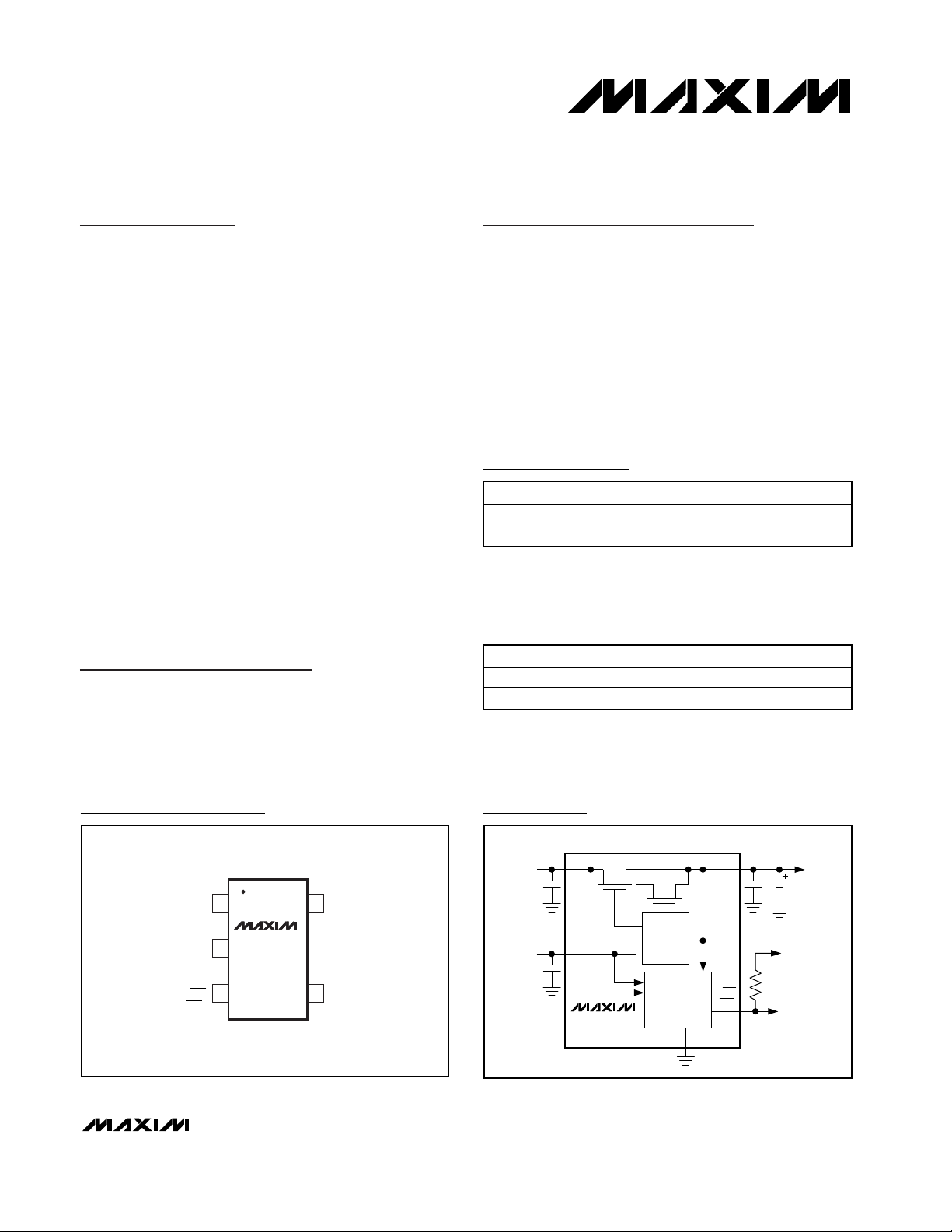
Pin Configuration
MAX1551
(MAX1555)
DC
USB
BAT
AC ADAPTER
3.7V TO 7V
USB
3.7V TO 6V
TO SYSTEM
LOAD
Li+
GND
TO LOGIC RAIL
CHARGE
CONTROL
POK
(CHG)
LOGIC
CONTROL
Typical Operating Circuit
*Protected by U.S. Patent #6,507,172.
Selector Guide
PART TEMP RANGE PIN-PACKAGE
MAX1551EZK-T -40°C to +85°C 5 Thin SOT23-5
MAX1555EZK-T -40°C to +85°C 5 Thin SOT23-5
PART TOP MARK FEATURES
MAX1551EZK ADRT POK Output
MAX1555EZK ADRU CHG Output
TOP VIEW
15BATUSB
MAX1551
2
GND
POK
(CHG)
(MAX1555)
34
THIN SOT23
DC
Page 2
MAX1551/MAX1555
SOT23 Dual-Input USB/AC Adapter 1-Cell Li+
Battery Chargers
2 _______________________________________________________________________________________
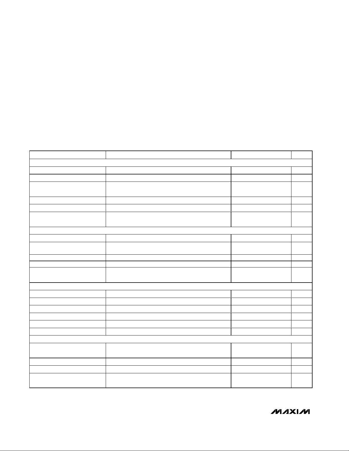
ABSOLUTE MAXIMUM RATINGS
ELECTRICAL CHARACTERISTICS
(VDC= 5V, V
USB
= 0, I
BAT
= 0, C
BAT
= 1µF, TA = 0°C to +85°C, unless otherwise noted.)
Stresses beyond those listed under “Absolute Maximum Ratings” may cause permanent damage to the device. These are stress ratings only, and functional
operation of the device at these or any other conditions beyond those indicated in the operational sections of the specifications is not implied. Exposure to
absolute maximum rating conditions for extended periods may affect device reliability.
DC to GND......................................................................0 to +8V
DC to BAT .......................................................................0 to +7V
BAT, CHG, POK, USB to GND .................................-0.3V to +7V
Continuous Power Dissipation (T
A
= +70°C)
5-Pin Thin SOT23 (derate 9.1mW/°C above +70°C)....727mW
Operating Temperature Range ...........................-40°C to +85°C
Junction Temperature Range ............................-40°C to +150°C
Storage Temperature Range .............................-65°C to +150°C
Lead Temperature (soldering, 10s) .................................+300°C
DC
DC Voltage Range (Note 1) 3.7 7.0 V
DC to BAT Voltage Range 0.1 6.0 V
DC Undervoltage Lockout
Threshold
DC Supply Current 1.75 3 mA
DC to BAT On-Resistance VDC = 3.7V, V
DC to BAT Dropout Voltage
USB
USB Voltage Range (Note 1) 3.7 6.0 V
USB Undervoltage Threshold
USB Supply Current V
USB to BAT On-Resistance V
USB to BAT Dropout Voltage
BAT
BAT Regulation Voltage VDC or V
DC Charging Current V
USB Charging Current V
BAT Prequal Threshold V
Prequalification Charging Current V
BAT Leakage Current VDC = V
POK, CHG, AND THERMAL LIMIT
CHG Threshold
CHG, POK Logic-Low Output I
CHG, POK Leakage Current V
Thermal-Limit Temperature
PARAMETER CONDITIONS MIN TYP MAX UNITS
Input rising, 430mV hysteresis, V
= 3.6V 1 2 Ω
BAT
When charging stops, V
DC falling, 200mV hysteresis
Input rising, 430mV hysteresis, V
V
= 3V (Note 1)
BAT
= 5V, VDC = 0 1.65 3 mA
USB
= 3.7V, V
USB
When charging stops, V
USB falling, 200mV hysteresis, V
= 3.3V, V
BAT
= 3.3V, VDC = 0, V
BAT
rising, 100mV hysteresis 2.9 3 3.1 V
BAT
= 2.8V 20 40 80 mA
BAT
Charge current where CHG goes high,
I
falling, 50mA hysteresis
BAT
, I
CHG
POK
, V
CHG
Charge current reduced by 17mA/°C above this
temperature
BAT
= 5V 4.158 4.2 4.242 V
USB
USB
= 0, V
USB
= 10mA 150 300 mV
= 6V, TA = +25°C 0.001 1 µA
POK
BAT
= 3.6V, VDC = 0 2 4 Ω
BAT
= 0, VDC = 5V 220 280 340 mA
USB
= 4.2V 5 µA
BAT
= 3V (Note 1) 3.75 3.95 4.15 V
BAT
= 4V,
= 0,
DC
= 4V,
= 0
DC
= 5V 80 90 100 mA
30 60 90 mV
3.75 3.95 4.15 V
30 60 90 mV
25 50 100 mA
+110 °C
Page 3
MAX1551/MAX1555
SOT23 Dual-Input USB/AC Adapter 1-Cell Li+
Battery Chargers
_______________________________________________________________________________________ 3
Note 1: The input undervoltage lockout has 430mV of hysteresis. The charger turns on when an input rises to 3.95V (typ), and turns
off when it falls below 3.52V.
Note 2: Specifications to -40°C are guaranteed by design, not production tested.
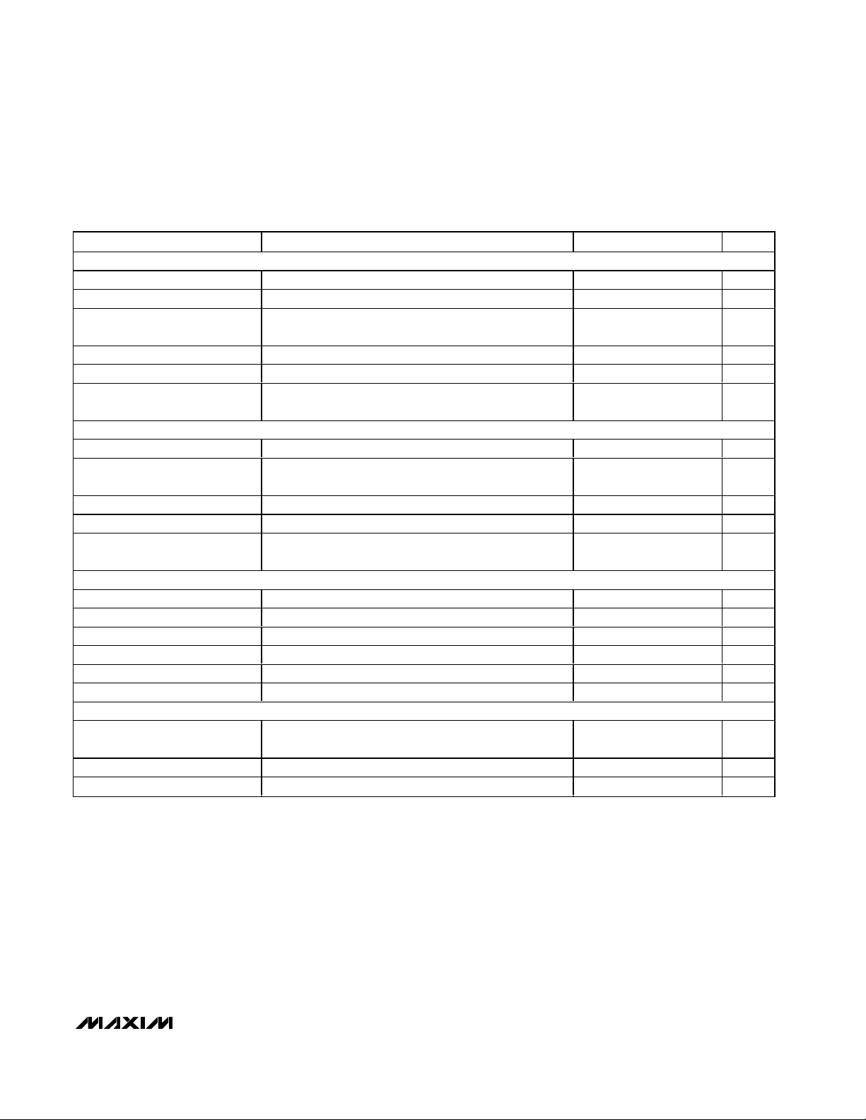
ELECTRICAL CHARACTERISTICS
(VDC= 5V, V
USB
= 0, I
BAT
= 0, C
BAT
= 1µF, TA = -40°C to +85°C, unless otherwise noted.) (Note 2)
DC
DC Voltage Range (Note 1) 3.7 7.0 V
DC to BAT Voltage Range 0.1 6.0 V
DC Undervoltage Lockout
Threshold
DC Supply Current 3mA
DC to BAT On-Resistance VDC = 3.7V, V
DC to BAT Dropout Voltage
USB
USB Voltage Range (Note 1) 3.7 6.0 V
USB Undervoltage Lockout
Threshold
USB Supply Current V
USB to BAT On-Resistance V
USB to BAT Dropout Voltage
BAT
BAT Regulation Voltage VDC or V
DC Charging Current V
USB Charging Current V
BAT Prequal Threshold V
Prequalification Charging Current V
BAT Leakage Current VDC = V
POK, CHG
CHG Threshold
CHG, POK Logic-Low Output I
CHG, POK Leakage Current V
PARAMETER CONDITIONS MIN MAX UNITS
Input rising, 430mV hysteresis, V
= 3.6V 2 Ω
BAT
When charging stops, V
hysteresis
Input rising, 430mV hysteresis, VDC = 0, V
(Note 1)
= 5V, VDC = 0 3 mA
USB
= 3.7V, V
USB
When charging stops, V
hysteresis, V
USB
= 3.3V, V
BAT
= 3.3V, VDC = 0, V
BAT
rising, 100mV hysteresis 2.9 3.1 V
BAT
= 2.8V 20 80 mA
BAT
USB
Charge current where CHG goes high,
falling, 50mA hysteresis
I
BAT
, I
CHG
POK
, V
CHG
POK
= 3.6V, VDC = 0 4 Ω
BAT
= 0
DC
= 5V 4.141 4.259 V
= 0, VDC = 5V 220 340 mA
USB
= 0, V
BAT
= 10mA 300 mV
= 6V, T
= 4V, DC falling, 200mV
BAT
= 4V, USB falling, 200mV
BAT
= 5V 80 100 mA
USB
= 4.2V 5 µA
= +25°C1µA
A
= 3V (Note 1) 3.75 4.15 V
BAT
= 3V
BAT
30 95 mV
3.75 4.15 V
30 95 mV
25 100 mA
Page 4

MAX1551/MAX1555
SOT23 Dual-Input USB/AC Adapter 1-Cell Li+
Battery Chargers
4 _______________________________________________________________________________________
Typical Operating Characteristics
(VDC= 5V, V
USB
= 0, I
BAT
= 0, C
BAT
= 1µF, TA = +25°C, unless otherwise noted.)
CHARGE CURRENT
vs. DC VOLTAGE HEADROOM
MAX1551/55 toc01
DC VOLTAGE HEADROOM (VDC - V
BAT
) (V)
CHARGE CURRENT (mA)
0.30.20.1
0
50
100
150
200
250
300
-50
00.50.4
V
BAT
= 3.8V, VDC FALLING
CHARGE CURRENT
vs. USB VOLTAGE HEADROOM
MAX1551/55 toc02
USB VOLTAGE HEADROOM (V
USB
- V
BAT
) (V)
CHARGE CURRENT (mA)
0.40.30.20.1
0
20
40
60
80
100
-20
00.5
VDC = 0, V
BAT
= 3.8V, V
USB
FALLING
DC CHARGE CURRENT
vs. BATTERY VOLTAGE
MAX1551/55 toc03
BATTERY VOLTAGE (V)
DC CHARGE CURRENT (mA)
4.03.53.02.52.01.51.00.5
0
50
100
150
200
250
300
-50
04.5
USB CHARGE CURRENT
vs. BATTERY VOLTAGE
MAX1551/55 toc04
BATTERY VOLTAGE (V)
USB CHARGE CURRENT (mA)
4.03.53.02.52.01.51.00.5
0
20
40
60
80
100
-20
04.5
DC CHARGE CURRENT
vs. AMBIENT TEMPERATURE
MAX1551/55 toc05
TEMPERATURE (°C)
DC CHARGE CURRENT (mA)
7565554535
0
50
100
150
200
250
300
-50
25 85
V
BAT
= 3.8V, VDC = 5V
THERMAL LIMIT ACTIVATED
BATTERY TERMINATION VOLTAGE
vs. TEMPERATURE
MAx1551/55 toc06
TEMPERATURE (°C)
BATTERY TERMINATION VOLTAGE (V)
35 6010-15
4.19
4.20
4.21
4.22
4.18
-40 85
BAT OPEN
OFF-BATTERY LEAKAGE CURRENT
vs. DC INPUT VOLTAGE
MAX1551/55 toc07
DC OR USB INPUT VOLTAGE (V)
OFF-BATTERY LEAKAGE CURRENT (µA)
4321
0.5
1.0
1.5
2.0
2.5
0
05
VDC = 0, SWEEPING USB
0 TO 5V OR V
USB
= 0,
SWEEPING DC 0 TO 5V
V
BAT
= 4.2V
USB-TO-DC TRANSITION WAVEFORM
MAX1551/55 toc08
400ms/div
V
USB
5V/div
V
DC
5V/div
0A
0V
0V
0V
BATTERY
CURRENT
200mA/div
V
POK
2V/div
Page 5

Detailed Description
The MAX1551/MAX1555 charge a single-cell Li+ battery from both USB and AC adapter sources, enabling
portable users to forgo carrying a wall cube. These
devices operate with no external FETs or diodes, and
accept operating input voltages up to 7V.
An internal thermal control loop simplifies PC board layout and allows optimum charging rate without the thermal limits imposed by worst-case battery and input
voltage. When the MAX1551/MAX1555 thermal limits
are reached, the chargers do not shut down, but simply
reduce charging current by 17mA/°C above a die temperature of +110°C.
With USB connected, but without DC power, the charge
current is set to 100mA (max). This allows charging
from both powered and unpowered USB hubs with no
port communication required. When DC power is connected, charging current is set at 280mA (typ). The
MAX1551/MAX1555 do not feature an enable input.
Once power is connected to USB and/or DC, the
charger is on.
When input power is removed, battery leakage current
is less than 5µA. No input-blocking diodes are required
to prevent battery drain. Insert a diode at DC (the
adapter input) if protection from negative voltage inputs
(reversed-polarity adapter plugs) is required.
USB to Adapter Power Handoff
The MAX1551/MAX1555 can charge from either the
USB input or the DC input. The battery does not charge
from both sources at the same time. The MAX1551/
MAX1555 automatically detect the active input and
charge from that. If both power sources are active, the
DC input takes precedence. The switchover between
DC and USB is detailed in Table 1.
MAX1551 Power-OK (
POK
)
The MAX1551’s POK is an active-low, open-drain output that goes low when VDCor V
USB
is above 3.95V.
POK can be used as a logic output or can drive an
LED. POK indicates the charger is connected to input
power and is charging.
MAX1555 Charge Status (
CHG
)
The MAX1555’s CHG is an active-low, open-drain
charge status indicator. CHG pulls low when the battery
is charging (whenever USB or DC are powered) and
charge current is greater than 50mA. CHG indicates
when the battery is fully charged by going high impedance when the charger is in voltage mode and charge
current falls below 50mA. Charging does not stop when
CHG goes high. CHG is low in precharge mode.
MAX1551/MAX1555
SOT23 Dual-Input USB/AC Adapter 1-Cell Li+
Battery Chargers
_______________________________________________________________________________________ 5
Pin Description
Table 1. USB and DC Input Selection
(VDCtakes precedence when both inputs are present.)
PIN NAME FUNCTION
1 USB
2 GND Ground
POK
3
CHG
4DC
5 BAT Battery Connection. Decouple BAT with a 1µF ceramic capacitor to GND.
USB Port Charger Supply Input. USB draws up to 100mA to charge the battery. Decouple USB with a 1µF
ceramic capacitor to GND.
Power-OK Active-Low Open-Drain Charger Status Indicator. POK pulls low when either charger source is
present (MAX1551 only).
Active-Low Open-Drain Charge Status Indicator. CHG pulls low when the battery is charging. CHG goes to a
high-impedance state, indicating the battery is fully charged, when the charger is in voltage mode and
charge current falls below 50mA. CHG is high impedance when both input sources are low (MAX1555 only).
DC Charger Supply Input for an AC Adapter. DC draws 280mA to charge the battery. Decouple DC with a
1µF ceramic capacitor to GND.
VDC > 7V OR V
Exceeds operating input range. Not allowed. See the
Absolute Maximum Ratings section.
USB
> 6V
V
> 3.95V AND
DC
DON’T CARE
V
USB
280mA (typ)
charging from DC
V
< 3.52V AND
DC
3.95V < V
100mA (max)
charging from USB
USB
< 6V
V
AND V
DC
Undervoltage lockout
USB
< 3.52V
Page 6

MAX1551/MAX1555
Precharge Current
The MAX1551/MAX1555 feature a precharge current to
protect deeply discharged cells. If V
BAT
is less than 3V,
the device enters precharge mode where charging current is limited to 40mA.
Package Thermal Limiting
On-chip thermal limiting in the MAX1551/MAX1555 simplifies PC board layout and allows charging rates to be
optimized without the limits imposed by worst-case battery and input voltages. The device reduces the power
dissipation at BAT to prevent overheating. This allows
the board design to be optimized for compact size and
typical thermal conditions. When the MAX1551/
MAX1555 thermal limits are reached, the chargers do
not shut down, but progressively reduce charging current by 17mA/°C above a die temperature of +110°C.
Solder the MAX1551/MAX1555s’ GND to a large
ground plane to help dissipate power and keep the die
temperature below the thermal limit. The USB charge
current of 100mA is unlikely to induce thermal limiting.
Bypass Capacitors
Use ceramic bypass capacitors at DC, USB, and BAT.
Mount these capacitors within 1cm of their respective
pins. X7R and X5R dielectrics are recommended.
Chip Information
TRANSISTOR COUNT: 541
PROCESS: BiCMOS
SOT23 Dual-Input USB/AC Adapter 1-Cell Li+
Battery Chargers
6 _______________________________________________________________________________________
Typical Application Circuit
AC ADAPTER
3.7V TO 7V
1µF
USB
3.7V TO 6V
1µF
DC
C1
USB
C2
MAX1551
(MAX1555)
CHARGE
CONTROL
CONTROL
LOGIC
BAT
C3
1µF
POK
(CHG)
GND
TO SYSTEM
LOAD
Li+
TO LOGIC RAIL
R1
100kΩ
INDICATES
THAT POWER
IS PRESENT
(EITHER DC
OR USB)
Page 7

MAX1551/MAX1555
SOT23 Dual-Input USB/AC Adapter 1-Cell Li+
Battery Chargers
_______________________________________________________________________________________ 7
Package Information
(The package drawing(s) in this data sheet may not reflect the most current specifications. For the latest package outline information,
go to www.maxim-ic.com/packages
.)
Page 8

MAX1551/MAX1555
SOT23 Dual-Input USB/AC Adapter 1-Cell Li+
Battery Chargers
Maxim cannot assume responsibility for use of any circuitry other than circuitry entirely embodied in a Maxim product. No circuit patent licenses are
implied. Maxim reserves the right to change the circuitry and specifications without notice at any time.
8 _____________________Maxim Integrated Products, 120 San Gabriel Drive, Sunnyvale, CA 94086 408-737-7600
© 2003 Maxim Integrated Products Printed USA is a registered trademark of Maxim Integrated Products.
Package Information (continued)
(The package drawing(s) in this data sheet may not reflect the most current specifications. For the latest package outline information,
go to www.maxim-ic.com/packages
.)
 Loading...