

Page 1
General Description
The MAX15000/MAX15001 current-mode PWM controllers contain all the control circuitry required for the
design of wide-input-voltage isolated and nonisolated
power supplies. The MAX15000 is well suited for universal input (rectified 85VAC to 265VAC) or telecom
(-36VDC to -72VDC) power supplies. The MAX15001
is well suited for low input voltage (9.5VDC to 24VDC)
power supplies.
The MAX15000/MAX15001 contain an internal error
amplifier that regulates the tertiary winding output voltage which is used in primary-side-regulated isolated
power supplies. Primary-side regulation eliminates the
need for an optocoupler. An input undervoltage lockout
(UVLO) is provided for programming the input-supply
start voltage and to ensure proper operation during
brownout conditions. An open-drain UVLO flag output,
with 210µs internal delay, allows the sequencing of a
secondary-side controller. The input-supply start voltage is externally programmable with a voltage-divider.
A UVLO/EN input is used to shutdown the MAX15000/
MAX15001. Internal digital soft-start eliminates output
voltage overshoot.
The MAX15000 has an internal bootstrap UVLO with
large hysteresis that requires a minimum 23.6V for startup. The MAX15001 does not have the internal bootstrap
UVLO and can be biased directly from a minimum voltage of 9.5V.
The switching frequency for the MAX15000/MAX15001 is
programmable with an external resistor. The MAX15000A/
MAX15001A provide a 50% maximum duty-cycle limit,
while the MAX15000B/MAX15001B provide a 75% maximum duty-cycle limit. These devices are available in 10pin µMAX®packages and are rated for operation over the
-40°C to +85°C temperature range.
Applications
1/2, 1/4, and 1/8th Brick Power Modules
High-Efficiency, Isolated Telecom Power
Supplies
Networking/Servers
Isolated Keep-Alive Power Supplies
12V Boost and SEPIC Regulators
Isolated and Nonisolated High-Brightness LED
Power Supplies
Industrial Power Conversion
Features
♦ Current-Mode Control
♦ Programmable Switching Frequency Up to 625kHz
♦ Accurate UVLO Threshold (1%)
♦ Open-Drain UVLO Flag Output with Internal Delay
♦ 36V to 72V Telecom Voltage Range
♦ Universal Offline Input Voltage Range
Rectified 85VAC to 265VAC (MAX15000)
♦ 9.5V to 24V Input (MAX15001)
♦ Digital Soft-Start
♦ Internal Bootstrap UVLO with Large Hysteresis
(MAX15000)
♦ Internal Error Amplifier with 1.5% Accurate
Reference
♦ 50µA (typ) Startup Supply Current
♦ 50% Maximum Duty-Cycle Limit
(MAX15000A/MAX15001A)
♦ 75% Maximum Duty-Cycle Limit
(MAX15000B/MAX15001B)
♦ 60ns Cycle-by-Cycle Current-Limit Propagation
Delay
♦ Available in Tiny 10-Pin µMAX Packages
MAX15000/MAX15001
Current-Mode PWM Controllers with
Programmable Switching Frequency
________________________________________________________________ Maxim Integrated Products 1
1
2
3
4
5
10
9
8
7
6
IN
V
CC
NDRV
GNDCOMP
FB
UFLG
UVLO/EN
MAX15000
MAX15001
µMAX
TOP VIEW
RTCS
Pin Configuration
Ordering Information
19-3957; Rev 0; 1/06
For pricing, delivery, and ordering information, please contact Maxim/Dallas Direct! at
1-888-629-4642, or visit Maxim’s website at www.maxim-ic.com.
Warning: The MAX15000/MAX15001 are designed to work with
high voltages. Exercise caution.
+Denotes lead-free package.
Selector Guide appears at end of data sheet.
PART
PIN-
PKG
CODE
MAX15000AEUB+
10 µMAX U10-2
MAX15000BEUB+
10 µMAX U10-2
MAX15001AEUB+
10 µMAX U10-2
MAX15001BEUB+
10 µMAX U10-2
µMAX is a registered trademark of Maxim Integrated Products, Inc.
TEMP RANGE
-40°C to +85°C
-40°C to +85°C
-40°C to +85°C
-40°C to +85°C
PACKAGE
Page 2
MAX15000/MAX15001
Current-Mode PWM Controllers with
Programmable Switching Frequency
2 _______________________________________________________________________________________
ABSOLUTE MAXIMUM RATINGS
ELECTRICAL CHARACTERISTICS
(VIN= +12V (for MAX15000, bring VINup to 23.6V for startup), 10nF bypass capacitors at IN and VCC, R12 = 15kΩ (MAX1500_A), R12
= 7.5kΩ (MAX1500_B), R15 = 1kΩ, C6 = 100nF (see the Typical Application Circuit), NDRV = open, V
UVLO/EN
= +1.4V, VFB= +1.0V,
COMP = open, V
CS
= 0V, TA= -40°C to +85°C, unless otherwise noted. Typical values are at TA= +25°C.) (Note 1)
Stresses beyond those listed under “Absolute Maximum Ratings” may cause permanent damage to the device. These are stress ratings only, and functional
operation of the device at these or any other conditions beyond those indicated in the operational sections of the specifications is not implied. Exposure to
absolute maximum rating conditions for extended periods may affect device reliability.
IN to GND ...............................................................-0.3V to +30V
IN Clamp (Internal Shunt) Current ........................................5mA
V
CC
to GND............................................................-0.3V to +13V
FB, COMP, UVLO/EN, RT, CS to GND .....................-0.3V to +6V
UFLG to GND .........................................................-0.3V to +30V
NDRV to GND ............................................-0.3V to (VCC+ 0.3V)
Continuous Power Dissipation (T
A
= +70°C)
10-Pin µMAX (derate 5.6mW/°C above +70°C) ........444.4mW
Operating Temperature Range ...........................-40°C to +85°C
Storage Temperature Range ............................-65°C to +150°C
Junction Temperature......................................................+150°C
Lead Temperature (soldering, 10s) .................................+300°C
PARAMETER
CONDITIONS MIN TYP MAX
UNITS
UVLO/STARTUP
Bootstrap UVLO Wake-Up Level V
SUVR
VIN rising (MAX15000 only)
21.6
V
Bootstrap UVLO Shutdown Level
V
SUVF
VIN falling (MAX15000 only) 9.05 9.74
V
UVLO/EN Wake-Up Threshold V
ULR2
UVLO/EN rising
1.23
V
UVLO/EN Shutdown Threshold V
ULF2
UVLO/EN falling 1.14 1.17 1.20 V
UVLO/EN Input Current I
UVLO
V
UVLO/EN
≤ 2V -50 +50 nA
UVLO/EN Hysteresis 60 mV
IN Supply Current In UVLO I
START
VIN = 19V, MAX15000 only when in
bootstrap UVLO
50 90 µA
IN Input Voltage Range V
IN
MAX15001 only 9.5 24.0 V
UVLO/EN steps up from 1V to 1.4V 3
UVLO/EN to UFLG Propagation
Delay (Figure 3)
UVLO/EN steps down from 1.4V to 1V 0.6
µs
t
EXTR
UVLO/EN steps up from 1V to 1.4V 3 10 ms
UVLO/EN to NDRV Propagation
Delay (Figure 3)
t
EXTF
UVLO/EN steps down from 1.4V to 1V 150 210 300 µs
t
BUVR
VIN steps up from 9V to 24V (MAX15000
only)
5
Bootstrap UVLO Propagation
Delay
t
BUVF
VIN steps down from 24V to 9V
(MAX15000 only)
1
µs
UFLG Low Output Voltage V
UFLGIUFLG
= 5mA sinking 0.8 V
UFLG High Output Leakage
Current
V
UFLG
= 25V 0.1 1 µA
INTERNAL SUPPLY
VCC Regulator Set Point V
CCSP
VIN = 10.8V to 24V, sinking 1µA to 20mA
from V
CC
7.0 10.5 V
IN Supply Current After Startup I
IN
VIN = 24V 2 4 mA
Shutdown Supply Current UVLO/EN = low 50 90 µA
SYMBOL
19.68
1.218
23.60
10.43
1.242
Page 3
MAX15000/MAX15001
Current-Mode PWM Controllers with
Programmable Switching Frequency
_______________________________________________________________________________________ 3
ELECTRICAL CHARACTERISTICS (continued)
(VIN= +12V (for MAX15000, bring VINup to 23.6V for startup), 10nF bypass capacitors at IN and VCC, R12 = 15kΩ (MAX1500_A), R12
= 7.5kΩ (MAX1500_B), R15 = 1kΩ, C6 = 100nF (see the Typical Application Circuit), NDRV = open, V
UVLO/EN
= +1.4V, VFB= +1.0V,
COMP = open, V
CS
= 0V, TA= -40°C to +85°C, unless otherwise noted. Typical values are at TA= +25°C.) (Note 1)
PARAMETER
CONDITIONS MIN TYP MAX
UNITS
GATE DRIVER
)
Measured at NDRV sinking 100mA 2 4
Driver Output Impedance
)
Measured at NDRV sourcing 20mA 4 10
Ω
Driver Peak Sink Current 1A
Driver Peak Source Current 0.65 A
PWM COMPARATOR
Comparator Offset Voltage V
PWM
V
COMP
- V
CS
1.24 1.38 1.54 V
CS Input Bias Current I
CS
VCS = 0V -4 +4 µA
Comparator Propagation Delay t
PWM
Change in VCS = 0.1V 60 ns
CURRENT-LIMIT COMPARATOR
Current-Limit Trip Threshold V
CS
900
1100 mV
CS Input Bias Current I
CS
VCS = 0V -4 +4 µA
Propagation Delay From
Comparator Input to NDRV
t
PDCS
100mV overdrive 60 ns
IN CLAMP VOLTAGE
IN Clamp Voltage V
INC
2mA sink current (Note 2) 24.1 26.1 29.0 V
ERROR AMPLIFIER
Voltage Gain R
LOAD
= 100kΩ 80 dB
Unity-Gain Bandwidth R
LOAD
= 100kΩ, C
LOAD
= 200pF 2
MHz
Phase Margin R
LOAD
= 100kΩ, C
LOAD
= 200pF 65
degrees
FB Input Offset Voltage ±1 mV
COMP High Voltage I
COMP
= 0 2.8
COMP Low Voltage I
COMP
= 0 1.1
V
Source Current 0.5 mA
Sink Current 0.5 mA
Reference Voltage V
REF
(Note 3)
V
Reference Voltage Accuracy -1.5 +1.5 %
FB Input Bias Current -50 +50 nA
COMP Short-Circuit Current 8mA
DIGITAL SOFT-START
NDRV
cycles
Soft-Start Duration t
SS
fSW = 350kHz 5.6 ms
Reference Voltage Steps During
Soft-Start
31
steps
Reference Voltage Step
mV
SYMBOL
R
ON(LOW
R
ON(HIGH
1000
1.230
1984
39.67
Page 4

MAX15000/MAX15001
Current-Mode PWM Controllers with
Programmable Switching Frequency
4 _______________________________________________________________________________________
Note 1: All devices are 100% tested at TA= +85°C. All limits over temperature are guaranteed by characterization.
Note 2: The MAX15000 is intended for use in universal input power supplies. The internal clamp circuit at IN is used to prevent the
bootstrap capacitor (C1 in Figure 1) from charging to a voltage beyond the absolute maximum rating of the device when
UVLO/EN is low (shutdown mode). Externally limit the maximum current to IN (hence to clamp) to 2mA maximum when
UVLO/EN is low. Clamp currents higher than 2mA may result in a clamp voltage higher than 30V, thus exceeding the
absolute maximum rating for IN. For the MAX15001, do not exceed the 24V maximum operating voltage of the device.
Note 3: V
REF
is measured with FB connected to COMP (see the Functional Diagram).
Note 4: The oscillator in the MAX1500_A is capable of operating up to 2500kHz. However, the NDRV switching frequency is limited
to operate up to 625kHz. Thus, the oscillator frequency for MAX1500_A must be limited to 1250kHz (maximum).
ELECTRICAL CHARACTERISTICS (continued)
(VIN= +12V (for MAX15000, bring VINup to 23.6V for startup), 10nF bypass capacitors at IN and VCC, R12 = 15kΩ (MAX1500_A), R12
= 7.5kΩ (MAX1500_B), R15 = 1kΩ, C6 = 100nF (see the Typical Application Circuit), NDRV = open, V
UVLO/EN
= +1.4V, VFB= +1.0V,
COMP = open, V
CS
= 0V, TA= -40°C to +85°C, unless otherwise noted. Typical values are at TA= +25°C.) (Note 1)
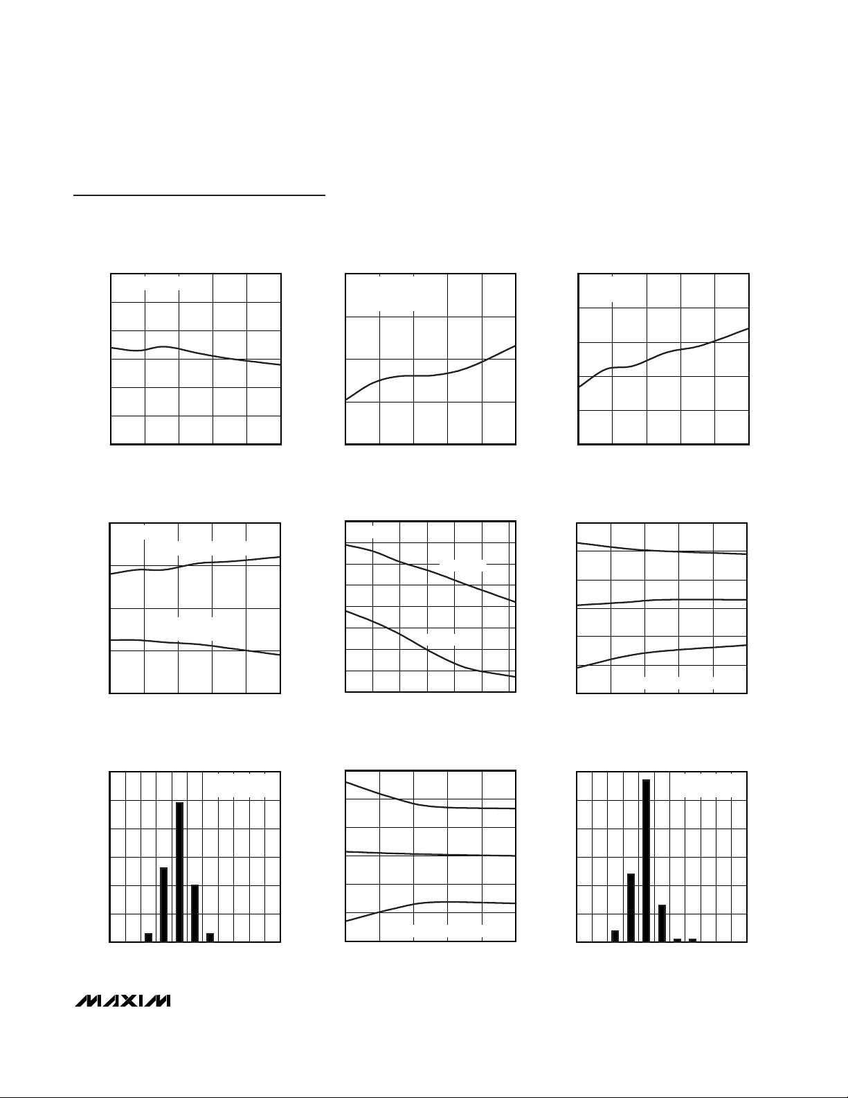
BOOTSTRAP UVLO WAKE-UP LEVEL
vs. TEMPERATURE
MAX15000 toc01
TEMPERATURE (°C)
V
IN
(V)
603510-15
21.4
21.5
21.6
21.7
21.8
21.3
-40 85
MAX15000 VIN RISING
BOOTSTRAP UVLO SHUTDOWN LEVEL
vs. TEMPERATURE
MAX15000 toc02
TEMPERATURE (°C)
V
IN
(V)
603510-15
9.5
9.7
9.9
10.1
10.3
9.3
-40 85
MAX15000 VIN FALLING
UVLO/EN WAKE-UP THRESHOLD
vs. TEMPERATURE
MAX15000 toc03
TEMPERATURE (°C)
UVLO/EN (V)
603510-15
1.226
1.228
1.230
1.232
1.234
1.236
1.224
-40 85
UVLO/EN RISING
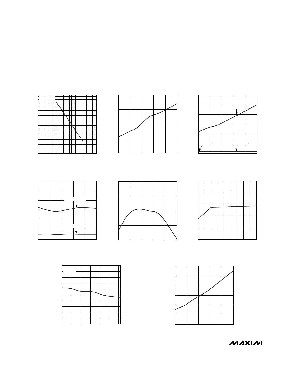
Typical Operating Characteristics
(V
UVLO/EN
= +1.4V, VFB= +1V, COMP = open, VCS= 0V, TA= +25°C, unless otherwise noted.)
PARAMETER
SYMBOL
CONDITIONS MIN TYP MAX
UNITS
OSCILLATOR
Oscillator Frequency Range f
OSC
50 2500 kHz
f
OSC
= 200kHz to 800kHz -10 +10
Oscillator Frequency Accuracy
f
OSC
= 50kHz to 2500kHz -20 +20
%
MAX1500_A, fSW = f
OSC
/2 25 625
NDRV Switching Frequency
(Note 4)
f
SW
MAX1500_B, fSW = f
OSC
/4 12.5
kHz
MAX1500_A 50
Maximum Duty Cycle D
MAX
MAX1500_B 75
%
625.0
Page 5
MAX15000/MAX15001
Current-Mode PWM Controllers with
Programmable Switching Frequency
_______________________________________________________________________________________ 5
UVLO/EN SHUTDOWN THRESHOLD
vs. TEMPERATURE
MAX15000 toc04
TEMPERATURE (°C)
V
UVLO/EN
(V)
603510-15
1.155
1.160
1.165
1.170
1.175
1.180
1.150
-40 85
UVLO/EN FALLING
VIN SUPPLY CURRENT IN UVLO
vs. TEMPERATURE
MAX15000 toc05
TEMPERATURE (°C)
I
START
(µA)
603510-15
50
55
60
65
45
-40 85
VIN = 19V
MAX15000 WHEN IN
BOOTSTRAP UVLO
VIN SUPPLY CURRENT AFTER
STARTUP vs. TEMPERATURE
MAX15000 toc06
TEMPERATURE (°C)
I
IN
(mA)
603510-15
1.6
1.7
1.8
1.9
2.0
1.5
-40 85
VIN = 24V
f
SW
= 350kHz
VCC REGULATOR SET POINT
vs. TEMPERATURE
MAX15000 toc07
TEMPERATURE (°C)
V
CC
(V)
603510-15
9.2
9.4
9.6
9.8
9.0
-40 85
VIN = 19V
NDRV NOT SWITCHING
NDRV SWITCHING
f
SW
= 350kHz
VCC REGULATOR SET POINT
vs. TEMPERATURE
MAX15000 toc08
TEMPERATURE (°C)
V
CC
(V)
6040-20 0 20
8.2
8.3
8.4
8.5
8.6
8.7
8.8
8.9
8.1
-40 80
10mA LOAD
VIN = 19V
20mA LOAD
CURRENT-LIMIT TRIP THRESHOLD
vs. TEMPERATURE
MAX15000 toc09
TEMPERATURE (°C)
CURRENT-LIMIT TRIP THRESHOLD (V)
603510-15
0.97
0.98
0.99
1.00
1.01
1.02
0.96
-40 85
-3σ
MEAN
+3σ
TOTAL NUMBER OF DEVICES = 140
CURRENT-LIMIT TRIP THRESHOLD
MAX15000 toc10
CURRENT-LIMIT TRIP THRESHOLD (V)
PERCENTAGE OF UNITS (%)
1.0220.993 1.0070.978
10
20
30
40
50
60
0
0.964 1.036
TOTAL NUMBER
OF DEVICES = 140
SWITCHING FREQUENCY
vs. TEMPERATURE
MAX15000 toc11
TEMPERATURE (°C)
SWITCHING FREQUENCY (kHz)
603510-15
330
335
340
345
350
355
325
-40 85
-3σ
MEAN
+3σ
TOTAL NUMBER OF DEVICES = 140
SWITCHING FREQUENCY
MAX15000 toc12
SWITCHING FREQUENCY (kHz)
PERCENTAGE OF UNITS (%)
354.0340.3 347.2333.5
10
20
30
40
50
60
0
326.7 360.8
TOTAL NUMBER
OF DEVICES = 140
Typical Operating Characteristics (continued)
(V
UVLO/EN
= +1.4V, VFB= +1V, COMP = open, VCS= 0V, TA= +25°C, unless otherwise noted.)
Page 6
MAX15000/MAX15001
Current-Mode PWM Controllers with
Programmable Switching Frequency
6 _______________________________________________________________________________________
SWITCHING FREQUENCY
vs. TIMING RESISTOR
MAX15000 toc13
TIMING RESISTOR (kΩ)
SWITCHING FREQUENCY (kHz)
10010
100
10001
1000
10
MAX15000A
PROPAGATION DELAY FROM
CURRENT-LIMIT COMPARATOR
INPUT TO NDRV vs. TEMPERATURE
MAX15000 toc14
TEMPERATURE (°C)
t
PDCS
(ns)
603510-15
45
50
55
60
40
-40 85
UVLO/EN TO NDRV PROPAGATION DELAY
vs. TEMPERATURE
MAX15000 toc15
TEMPERATURE (°C)
UVLO DELAY (ms)
603510-15
1
2
3
4
5
6
0
-40 85
UVLO/EN RISING
UVLO/EN FALLING
206µs
UVLO/EN TO UFLG PROPAGATION DELAY
vs. TEMPERATURE
MAX15000 toc16
TEMPERATURE (°C)
UVLO DELAY (µs)
603510-15
1
2
3
4
5
6
0
-40 85
UVLO/EN RISING
UVLO/EN FALLING
REFERENCE VOLTAGE
vs. TEMPERATURE
MAX15000 toc17
TEMPERATURE (°C)
REFERENCE VOLTAGE (V)
603510-15
1.229
1.230
1.231
1.232
1.228
-40 85
VIN = 12V
INPUT CURRENT
vs. IN VOLTAGE
MAX15000 toc18
IN VOLTAGE (V)
INPUT CURRENT (mA)
1817161514131211
1.64
1.68
1.72
1.76
1.80
1.60
10 19
UVLO/EN = 1.4V
NDRV SWITCHING AT 350kHz
INPUT CLAMP VOLTAGE
vs. TEMPERATURE
MAX15000 toc19
TEMPERATURE (°C)
INPUT CLAMP VOLTAGE (V)
6040200-20
25.2
25.4
25.6
25.8
26.0
26.2
26.4
26.6
26.8
27.0
25.0
-40 80
IIN = 2mA
NDRV LOW OUTPUT IMPEDANCE
vs. TEMPERATURE
MAX15000 toc20
TEMPERATURE (°C)
R
ON
(Ω)
603510-15
1.4
1.6
1.8
2.0
2.2
2.4
1.2
-40 85
VIN = 24V
SINKING 100mA
Typical Operating Characteristics (continued)
(V
UVLO/EN
= +1.4V, VFB= +1V, COMP = open, VCS= 0V, TA= +25°C, unless otherwise noted.)
Page 7

MAX15000/MAX15001
Current-Mode PWM Controllers with
Programmable Switching Frequency
_______________________________________________________________________________________ 7
Pin Description
PIN
FUNCTION
1
Externally Programmable Undervoltage Lockout. UVLO/EN programs the input start voltage. Connect
UVLO/EN to GND to disable the device. NDRV stops switching approximately 210µs after the UVLO/EN
voltage falls below 1.17V.
2 UFLG
Open-Drain Undervoltage Flag Output. UFLG is asserted low as soon as the UVLO/EN voltage falls below its
threshold.
3FBError-Amplifier Inverting Input
4
Error-Amplifier Output
5CS
Current-Sense Input. Current-sense connection for PWM regulation and cycle-by-cycle current limit.
Connect to the high side of the sense resistor. An RC filter may be necessary to eliminate leading-edge
spikes. Current-limit trip voltage is 1V.
6RT
Oscillator Timing Resistor Input. An RC network may be required to reduce jitter (see the Typical Application
Circuit).
7 GND Ground Connection
8
External n-Channel MOSFET Gate Connection
9V
CC
Gate-Drive Supply. Internally generated supply from IN. Decouple VCC with a 10nF or larger capacitor
to GND.
10 IN
IN Supply. Decouple with a 10nF or larger capacitor to GND. For bootstrapped operation (MAX15000),
connect a startup resistor from the input supply line to IN. Connect the bias winding supply to IN also (see
the Typical Operating Circuit). For the MAX15001, connect IN directly to the 9.5V to 24V supply.
Typical Operating Characteristics (continued)
(V
UVLO/EN
= +1.4V, VFB= +1V, COMP = open, VCS= 0V, TA= +25°C, unless otherwise noted.)
NDRV HIGH OUTPUT IMPEDANCE
5.0
4.6
4.2
(Ω)
ON
R
3.8
3.4
3.0
-40 85
vs. TEMPERATURE
SOURCING 20mA
TEMPERATURE (°C)
NAME
MAX15000 toc21
603510-15
ERROR AMPLIFIER OPEN-LOOP GAIN
100
GAIN (dB)
-20
-40
-60
AND PHASE vs. FREQUENCY
80
60
40
20
0
10.1 10 100 1k 10k 100k 1M 10M 100M
PHASE
FREQUENCY (Hz)
MAX15000 toc22
GAIN
120
80
40
0
-40
-80
-120
-160
-200
PHASE (DEGREES)
UVLO/EN
COMP
NDRV
Page 8

MAX15000/MAX15001
Detailed Description
The MAX15000/MAX15001 current-mode PWM controllers are ideal for isolated and nonisolated powersupply applications. The devices offer an accurate
input startup voltage programmable through the
UVLO/EN input. This feature prevents the power supply
from entering a brownout condition in case the input
voltage sags below its minimum value. This is important
since switching power supplies increases their input
supply current as the input voltage drops to keep the
output power constant. In addition to this externally
adjustable UVLO feature, the MAX15000 also offers a
bootstrap UVLO with a large hysteresis (11.9V) and
very low startup and operating current, which result in
an efficient universal input power supply. The switching
frequency of the MAX15000/MAX15001 is programmable with an external resistor.
The MAX15000 is well suited for universal input (rectified 85VAC to 265VAC) or telecom (-36VDC to
-72VDC) power supplies. The MAX15001 is well suited
for low-input voltage (9.5VDC to 24VDC) power supplies. The devices include an internal clamp at IN to
prevent the input voltage from exceeding the absolute
maximum rating (see Note 2 at the end of the Electrical
Characteristics table). The input is clamped when the
devices are started with a bleed resistor (R1 in Figure 1)
from a high input voltage and the UVLO/EN input is low.
The clamp can safely sink up to 2mA current.
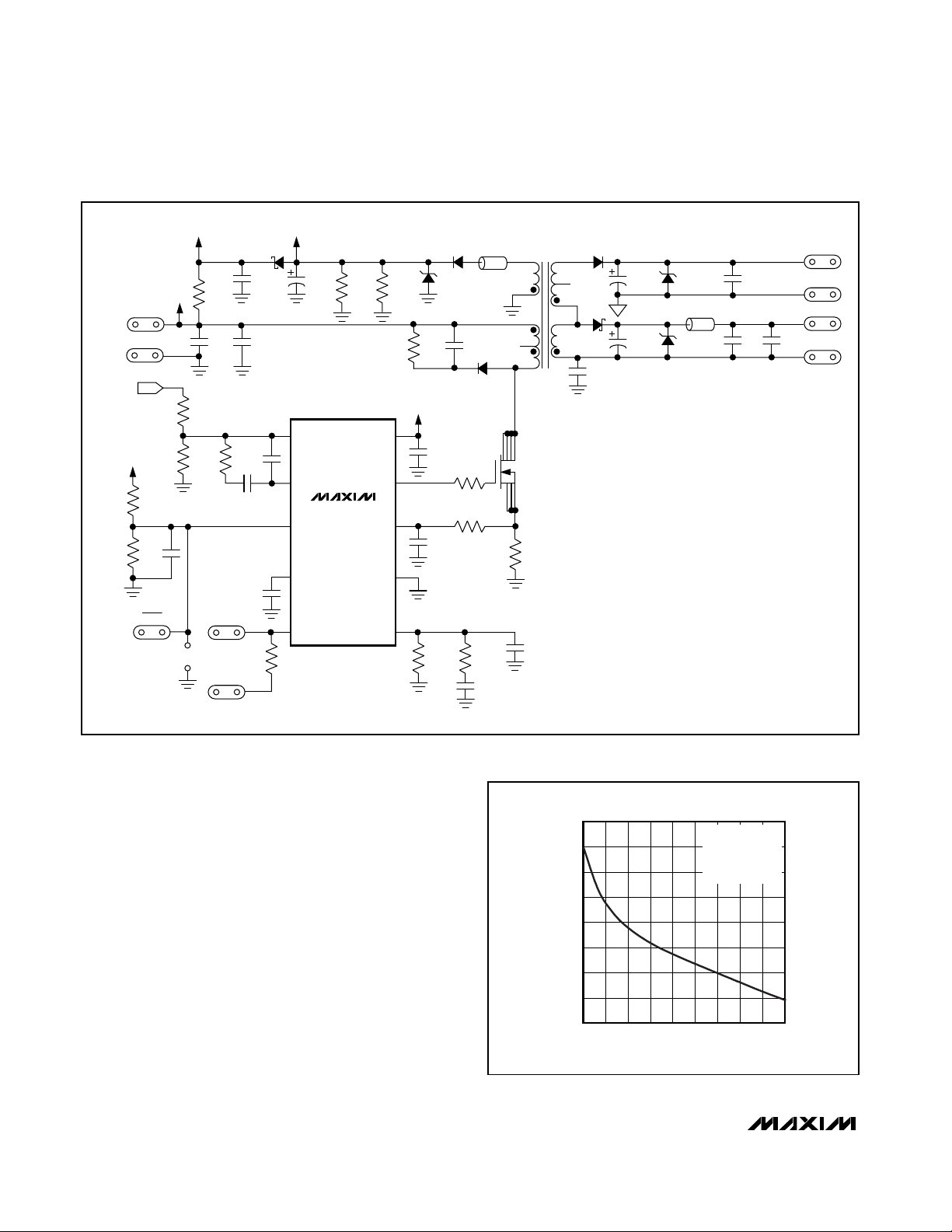
Power supplies designed with the MAX15000 use a
high-value startup resistor R1 that charges a reservoir
capacitor C1 (see Figure 1). During this initial period,
while the voltage is less than the internal bootstrap
UVLO threshold, the device typically consumes only
50µA of quiescent current. This low startup current and
the large bootstrap UVLO hysteresis help to minimize
the power dissipation across R1 even at the high end of
the universal AC input voltage (265VAC).
The MAX15000/MAX15001 include a cycle-by-cycle
current limit that turns off the gate drive to the external
MOSFET whenever the internally set threshold of 1V is
exceeded. When using the MAX15000 in the bootstrapped mode, if the power-supply output is shorted,
the tertiary winding voltage will drop below the internally set threshold causing the UVLO to turn off the gate
drive to the external power MOSFET. This will reinitiate
a startup sequence with soft-start.
Current-Mode PWM Controllers with
Programmable Switching Frequency
8 _______________________________________________________________________________________
8
9
10
3
2
1
UVLO/EN
IN
7
4
V
CC
NDRV
GND
UFLG
FB
COMP
6
5
RT
CS
T1
R3
R2
R12
R1
R4
C5
C2
C2
C1
C4
D2
D1
C6
R11
V
SUPPLY
0V
R13
R14
V
OUT
R15
Q1
MAX15000
Figure 1. Nonisolated Power Supply with Programmable Input-Supply Start Voltage
Page 9

Current-Mode Control Loop
The advantages of current-mode control over voltagemode control are twofold. First, there is the feed-forward characteristic brought on by the controller’s
ability to adjust for variations in the input voltage on a
cycle-by-cycle basis. Secondly, the stability requirements of the current-mode controller are reduced to
that of a single-pole system unlike the double pole in
voltage-mode control.
The MAX15000/MAX15001 use a current-mode control
loop where the output of the error amplifier (COMP) is
compared to the current-sense voltage at CS. When the
current-sense signal is lower than the noninverting
input of the PWM comparator, the output of the CPWM
comparator is low and the switch is turned on at each
clock pulse. When the current-sense signal is higher than
the inverting input of the CPWM, the output of the CPWM
comparator goes high and the switch is turned off.
Undervoltage Lockout
The MAX15000/MAX15001 provide a UVLO/EN input.
The threshold for UVLO is 1.23V with 60mV hysteresis.
Before any operation can commence, the voltage on
UVLO/EN has to exceed 1.23V. The UVLO circuit keeps
the CPWM comparator, ILIM comparator, oscillator,
and output driver shut down to reduce current consumption (see the Functional Diagram).
Use this UVLO/EN input to program the input-supply
start voltage. For example, a reasonable start voltage
for a 36V to 72V telecom range is usually 34V.
Calculate the resistor-divider values, R2 and R3 (see
Figure 1) by using the following formulas:
where I
UVLO
is the UVLO/EN input current (50nA max),
and V
ULR2
is the UVLO/EN wake-up threshold (1.23V).
VINis the value of the input-supply voltage where the
power supply must start. The value of R3 is calculated
to minimize the voltage-drop error across R2 as a result
of the input bias current of the UVLO/EN input.
MAX15000 Bootstrap UVLO
In addition to the externally programmable UVLO function offered in both the MAX15000 and MAX15001, the
MAX15000 includes an internal bootstrap UVLO that is
very useful when designing high-voltage power supplies (see the Functional Diagram). This allows the
device to bootstrap itself during initial power-up. The
MAX15000 attempts to start when VINexceeds the
bootstrap UVLO threshold of 21.6V. During startup, the
UVLO circuit keeps the CPWM comparator, ILIM comparator, oscillator, and output driver shut down to
reduce current consumption. Once V
IN
reaches 21.6V,
the UVLO circuit turns on the CPWM and ILIM comparators, the oscillator, and allows the output driver to
switch. If VINdrops below 1.17V, the UVLO circuit shuts
down the CPWM comparator, ILIM comparator, oscillator, and output driver returning the MAX15000 to the
low-current startup mode.
Startup Operation
The MAX15001 starts up when the voltage at IN
exceeds 9.5V and the UVLO/EN input is greater than
1.23V. However, the MAX15000 requires that, in addition to meeting the specified startup conditions for the
MAX15001, the voltage at IN exceeds the bootstrap
UVLO threshold of 21.6V.
For the MAX15000, the voltage at IN is normally derived
from a tertiary winding of the transformer. However, at
startup there is no energy being delivered through the
transformer, hence, a special bootstrap sequence is
required. Figure 2 shows the voltages at IN and V
CC
during startup. Initially, both VINand VCCare 0V. After
the line voltage is applied, C1 charges through the
startup resistor, R1, to an intermediate voltage. At this
point, the internal regulator begins charging C2 (see
Figure 1). Only 50µA of the current supplied through R1
is used by the MAX15000, the remaining input current
charges C1 and C2. The charging of C2 stops when
the VCCvoltage reaches approximately 9.5V, while the
voltage across C1 continues rising until it reaches the
wake-up level of 21.6V. Once VINexceeds the bootstrap UVLO threshold, NDRV begins switching the
MOSFET and transfers energy to the secondary and
tertiary outputs. If the voltage on the tertiary output
builds to higher than 9.74V (the bootstrap UVLO lower
R
VV
IVV
R
VV
V
R
ULR IN
UVLO IN ULR
IN ULR
ULR
3
500
23
2
2
2
2
≅
−
=
−
()
MAX15000/MAX15001
Current-Mode PWM Controllers with
Programmable Switching Frequency
_______________________________________________________________________________________ 9
Page 10
MAX15000/MAX15001
threshold), then startup has been accomplished and
sustained operation will commence. If VINdrops below
9.74V before startup is complete, the device goes back
to low-current UVLO. In this case, increase the value of
C1 to store enough energy to allow for the voltage at
the tertiary winding to build up.
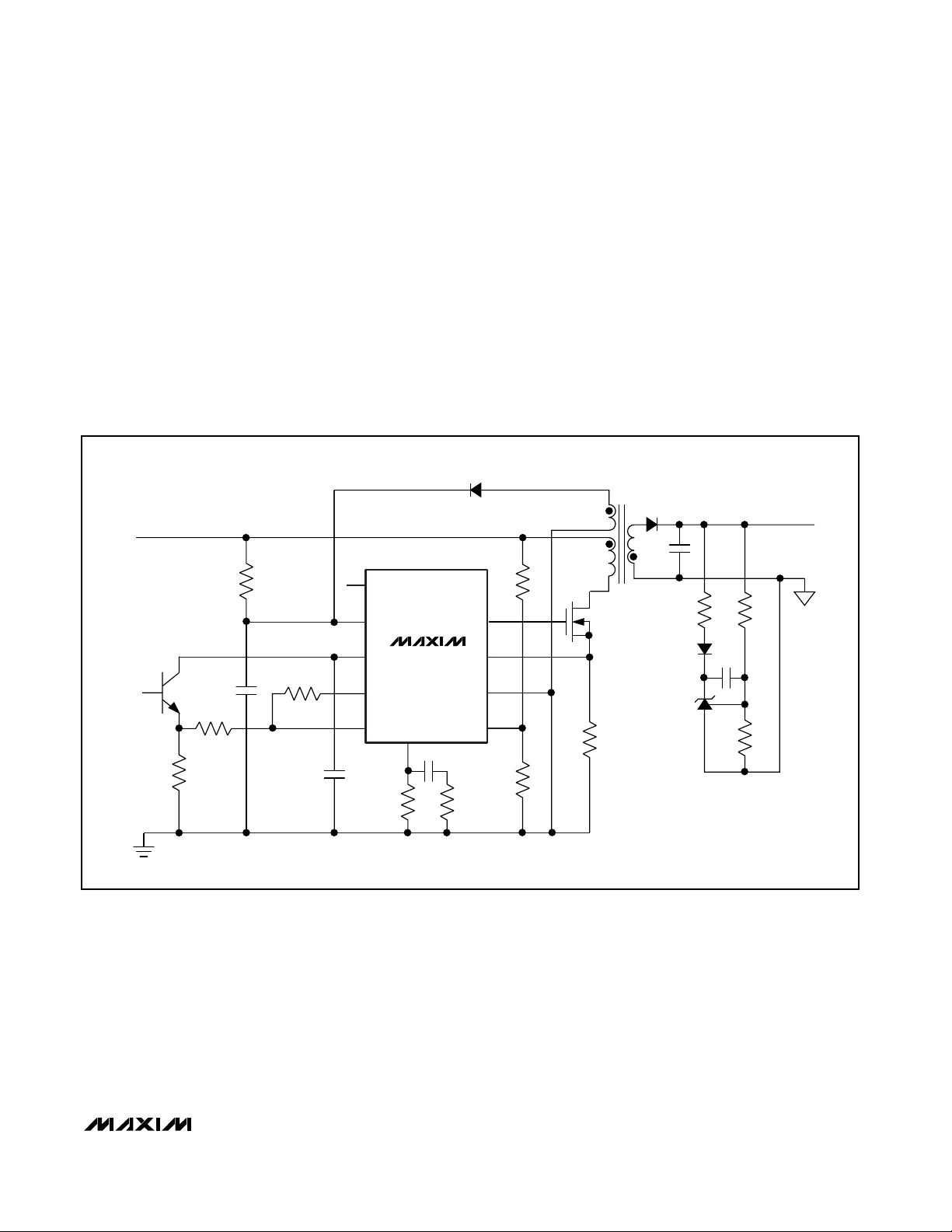
UVLO Flag (UFLG)
The MAX15000/MAX15001 have an open-drain undervoltage flag output (UFLG). When used with an optocoupler the UFLG output can serve to sequence a
secondary-side controller. An internal 210µs delay
occurs the instant the voltage on UVLO/EN drops
below 1.17V until NDRV stops switching. This allows for
the UFLG output to change state before the MAX15000/
MAX15001 shut down (Figure 3).
When the voltage at the UVLO/EN is above the threshold, UFLG is high impedance. When UVLO/EN is below
the threshold, UFLG goes low. UFLG is not affected by
bootstrap UVLO (MAX15000).
Soft-Start
The MAX15000/MAX15001 soft-start feature allows the
output voltage to ramp up in a controlled manner, eliminating voltage overshoot. The MAX15000/MAX15001
reference generator that is internally connected to the
error amplifier soft-starts to achieve superior control of
the output voltage under heavy and light load conditions. Soft-start begins after UVLO is deasserted (VINis
above 21.6V for the MAX15000, VINis above 9.5V for
the MAX15001, and the voltage on UVLO/EN is above
1.23V). The voltage applied to the noninverting node of
the amplifier ramps from 0 to 1.23V in 1984 NDRV
switching cycles. Use the following formula to calculate
the soft-start time (tSS):
where f
NDRV
is the switching frequency at the NDRV
output. Figure 4 shows the soft-start regulated output of
a power supply using the MAX15000 during startup.
t
f
SS
NDRV
=
1984
Current-Mode PWM Controllers with
Programmable Switching Frequency
10 ______________________________________________________________________________________
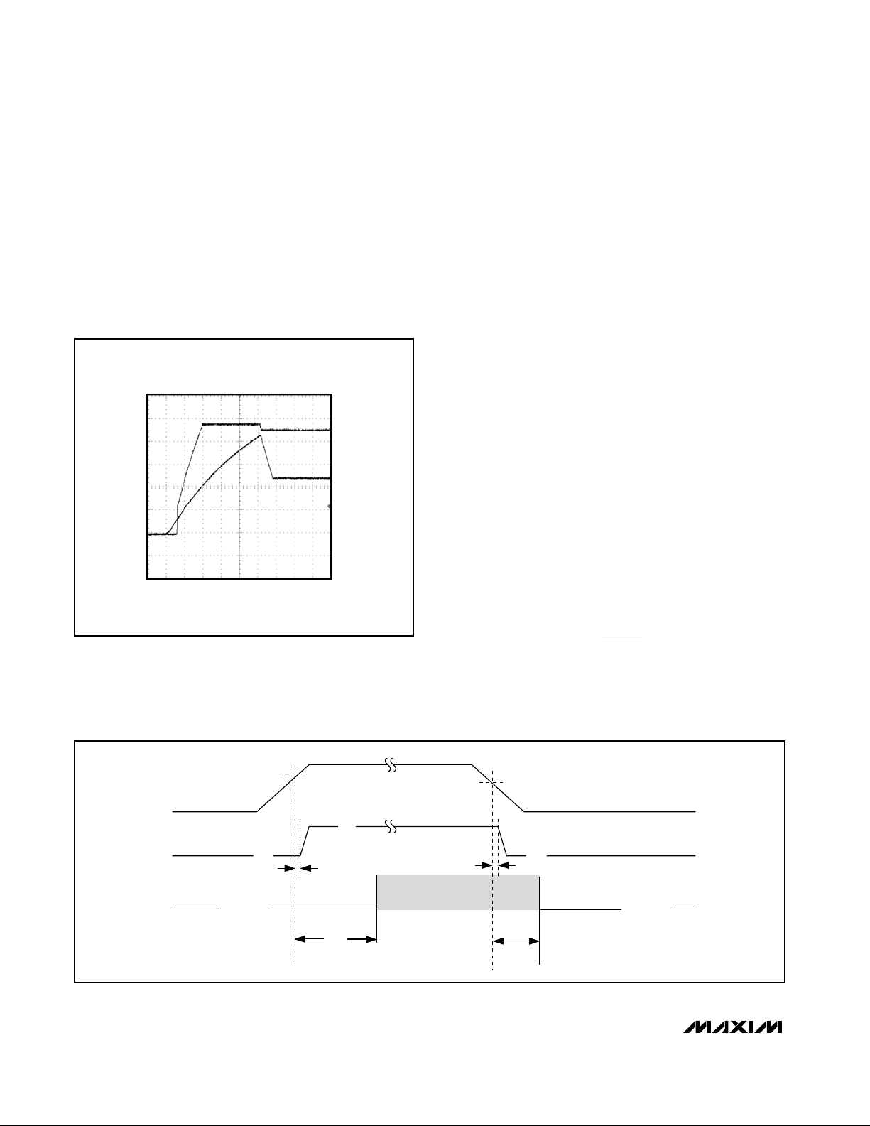
MAX15000 fig02
100ms/div
V
CC
2V/div
V
IN
5V/div
0V
Figure 2. VINand VCCDuring Startup When Using the
MAX15000 in Bootstrapped Mode (Figure 1)
V
UVLO/EN
LOW
LOW
Hi-Z
V
UFLG
V
NDRV
SHUTDOWN
SHUTDOWN
t
EXTR
3ms
1.23V
(±1%)
1.17V (typ)
t
EXTF
210µs
0.6µs
3µs
NDRV SWITCHING
Figure 3. UVLO/EN and UFLG Operation Timing
Page 11

n-Channel MOSFET Switch Driver
The NDRV output drives an external n-channel MOSFET.
The internal regulator output (VCC), set to approximately
9V, drives NDRV. For the universal input voltage range,
the MOSFET used must withstand the DC level of the
high-line input voltage plus the reflected voltage at the
primary of the transformer. Most applications that use the
discontinuous flyback topology require a MOSFET rated
at 600V. NDRV can source/sink in excess of 650/1000mA
peak current; therefore, select a MOSFET that will yield
acceptable conduction and switching losses.
Oscillator/Switching Frequency
Use an external resistor at RT to program the
MAX15000/MAX15001 internal oscillator frequency
between 50kHz and 2.5MHz. The MAX15000A/
MAX15001A output switching frequency is one-half of
the programmed oscillator frequency with a 50% duty
cycle. The MAX15000B/MAX15001B output switching
frequency is one-quarter of the programmed oscillator
frequency with a 75% duty cycle.
The MAX15000A/MAX15001A and MAX15000B/
MAX15001B have programmable output switching frequencies from 25kHz to 625kHz and 12.5kHz to
625kHz, respectively. Use the following formulas to
determine the appropriate value of the resistor R12
(see Figure 1) needed to generate the desired output
switching frequency (fSW) at the NDRV output:
where R12 is the resistor connected from RT to GND
(see Figure 1).
Connect an RC network in parallel with R12 as shown in
Figure 1. The RC network should consist of a 100nF
capacitor C6 (for stability) in series with resistor R15
which serves to further minimize jitter. Use the following
formula to determine the value of R15:
For example, if R12 is 4kΩ, R15 becomes 707Ω.
Internal Error Amplifier
The MAX15000/MAX15001 include an internal error
amplifier to regulate the output voltage in the case of a
nonisolated power supply (see Figure 1). For the circuit
in Figure 1, calculate the output voltage using the following equation:
where V
REF
= 1.23V. The amplifier’s noninverting input
is internally connected to a digital soft-start circuit that
gradually increases the reference voltage during startup applied to this input. This forces the output voltage
to come up in an orderly and well-defined manner
under all load conditions.
The error amplifier may also be used to regulate the tertiary winding output which implements a primary-sideregulated, isolated power supply (see Figure 6). For the
circuit in Figure 6, calculate the output voltage using
the following equation:
where N
S
is the number of secondary winding turns, N
T
is the number of tertiary winding turns, and both V
D6
and VD2are the diode drops at the respective outputs.
V
N
N
R
R
VVV
OUT
S
T
REF D D
=+
+
−1
1
2
62
V
R
R
V
OUT REF
=+
1
13
14
RR15 88 9 12
1
4
. =×
()
R
f
for the MAX A MAX A
R
f
for the MAX B MAX B
SW
SW
12
10
2
15000 15001
12
10
4
15000 15001
10
10
=
=
/.
/.
MAX15000/MAX15001
Current-Mode PWM Controllers with
Programmable Switching Frequency
______________________________________________________________________________________ 11
MAX15000 fig04
2ms/div
V
OUT
2V/div
100mA LOAD ON/V
OUT1
100mA LOAD ON/V
OUT2
Figure 4. Primary-Side Output Voltage Soft-Start During Initial
Startup for the Circuit in Figure 6
Page 12

MAX15000/MAX15001
Current Limit
The current-sense resistor (R4 in Figure 1), connected
between the source of the MOSFET and ground, sets the
current limit. The current-limit comparator has a voltage
trip level (VCS) of 1V. Use the following equation to calculate the value of R4:
where I
PRI
is the peak current in the primary side of the
transformer which also flows through the MOSFET.
When the voltage produced by this current (through the
current-sense resistor) exceeds the current-limit comparator threshold, the MOSFET driver (NDRV) terminates the current on-cycle within 60ns (typ). Use a
small RC network to filter out the leading-edge spikes
on the sensed waveform when needed. Set the corner
frequency between 2MHz and 10MHz.
Applications Information
Startup Time Considerations for Power
Supplies Using the MAX15000
The bypass capacitor at IN, C1, supplies current immediately after the MAX15000 wakes up (see Figure 1).
The size of C1 and the connection configuration of the
tertiary winding determine the number of cycles available for startup. Large values of C1 increase the startup time but also supply gate charge for more cycles
during initial startup. If the value of C1 is too small, V
IN
drops below 9.74V because NDRV does not have
enough time to switch and build up sufficient voltage
across the tertiary output which powers the device. The
device goes back into UVLO and does not start. Use a
low-leakage capacitor for C1 and C2.
Typically, offline power supplies keep startup times to
less than 500ms even in low-line conditions (85VAC
input for universal offline or 36VDC for telecom applications). Size the startup resistor, R1, to supply both the
maximum startup bias of the device (90µA) and the
charging current for C1 and C2. The bypass capacitor,
C2, must charge to 9.5V and C1 to 24V, all within the
desired time period of 500ms. Because of the internal
soft-start time of the MAX15000 (approximately 5.6ms
when f
SW
= 350kHz), C1 must store enough charge to
deliver current to the device for at least this much time.
To calculate the approximate amount of capacitance
required, use the following formula:
where IINis the MAX15000’s internal supply current
(2mA) after startup, Q
gtot
is the total gate charge for
Q1, fSWis the MAX15000’s switching frequency
(350kHz), V
HYST
is the bootstrap UVLO hysteresis
(approximately 12V) and tSSis the internal soft-start
time (5.6ms).
Example: Ig= (8nC) (350kHz) ≅ 2.8mA
Choose a 2.2µF standard value (assuming 350kHz
switching frequency).
Assuming C1 > C2, calculate the value of R1 as follows:
where V
IN(MIN)
is the minimum input supply voltage for
the application (36V for telecom), V
SUVR
is the boot-
strap UVLO wake-up level (23.6V max), I
START
is the IN
supply current at startup (90µA max).
For example:
Choose a 120kΩ standard value.
()(.)
()
.
()()
(. ) ( )
.
I
VF
ms
mA
R
VV
mA A
k
C1
24 2 2
500
0 105
1
36 12
0 105 90
123 07
==
≅
−
+
=
µ
µ
Ω
I
VC
ms
R
VV
II
C
SUVR
IN MIN SUVR
C START
1
1
1
500
1=≅
−
+
()
()
C
mA mA ms
V
F1
22856
12
224=
+
=
(.)(.)
. µ
IQ f
C
IIt
V
ggtotSW
IN g SS
HYST
=
=+1
()()
R
V
I
CS
PRI
4 =
Current-Mode PWM Controllers with
Programmable Switching Frequency
12 ______________________________________________________________________________________
Page 13
Choose a higher value for R1 than the one calculated in
the previous equation if a longer startup time can be
tolerated to minimize power loss on this resistor.
The above startup method is applicable to a circuit similar to the one shown in Figure 1. In this circuit, the tertiary winding has the same phase as the output
windings. Thus, the voltage on the tertiary winding at any
given time is proportional to the output voltage and goes
through the same soft-start period as the output voltage.
The minimum discharge time of C1 from 21.6V to 9.74V
must be greater than the soft-start time of 5.6ms.
Another method for bootstrapping the power supply is
to use a bias winding that is in phase with the MOSFET
on-time (see Figure 5). In this case, the amount of
capacitance required at IN (C1) is much smaller.
However, the input voltage cannot have a range
greater than approximately 2:1 (primary winding voltage to bias winding voltage ratio).
For hiccup-mode fault protection, make the bias winding in phase with the output, then the power-supply hiccups and soft-starts under output short-circuit
conditions. The power supply does not hiccup if the
bias winding is in phase with the MOSFET on-time.
MAX15000/MAX15001
Current-Mode PWM Controllers with
Programmable Switching Frequency
______________________________________________________________________________________ 13
VCC
COMP
FB
GND
CS
NDRV
UVLO/EN
V
IN
R1
R2
R3
R4
D1
T1
C1
C2
R5
R6
R7
U2
OPTO
TRANS.
RT
UFLG
C6
R15
R12
C4
IN
MAX15000A
U1
C3
U3
TL431
U2
OPTO LED
R9
V
OUT
R8
R10
D2
Q1
Figure 5. Secondary-Side Regulated, Isolated Power Supply
Page 14
MAX15000/MAX15001
Primary-Side-Regulated,
Isolated Telecom Power Supply
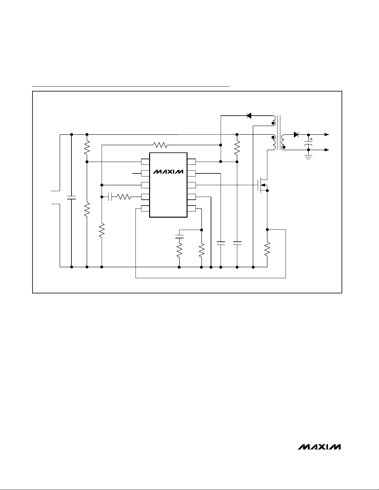
Figure 6 shows a complete circuit of a dual-output
power supply with a telecom voltage range of 36V to
72V. An important aspect of this power supply is that it
is primary-side regulated. The regulation through the
tertiary winding also supplies bias for the MAX15000.
In the circuit of Figure 6, cross-regulation has been
improved (tertiary and 5V outputs) by using chip inductors, L1 and L2, and R7||R12 across C12. R7||R12 presents enough loading on the tertiary winding output to
allow ±10% load regulation on the 5V output over a
load current range from 150mA to 1.5A (Figure 7).
Current-Mode PWM Controllers with
Programmable Switching Frequency
14 ______________________________________________________________________________________
MAX15000A
U1
+VIN
UFLG
-VIN
VOUT2
15V/100mA
5V/1.5A
SGND
VOUT1
SGND
1
2
1
2
3
3
2
1
4
4
6
7
8
5
T1
D2
D3
OPEN
D6
D8
D1
10
D7
OPEN
R12
1.2kΩ
7
9
8
6
C6
0.0047µF
250VAC
C3
68µF
6.3V
5T
12T
D5
C15
1µF
D4
L1
C13
1µF
C4
22µF
6.3V
28T
35µH
15T
5
N1
IRF7464
R7
1.2kΩ
R8
OPEN
C10
OPEN
R5
0.600Ω
1%
R15
750Ω
C16
1µF
35V
R6
33kΩ
C5
47µF
25V
L2
FB_P
IN
36V TO 72V
IN
+VIN
10
IN
NDRV
CS
GND
FB_P
RT
8
5
6
7
FB
COMP
UVLO/EN
UFLG
NOTE: MOSFET N1 = IR IRF7464.
V
CC
JU1
3
4
1
2
9
+VIN
C12
15µF
35V
R14
14.3kΩ
1%
C17
OPEN
C9
100pF
C14
3900pF
R4
51.1kΩ
R3
1.37MΩ
1%
R9
75kΩ
1%
R2
2.49kΩ
1%
R1
22.6kΩ
1%
R13
10kΩ
C8
OPEN
C7
0.22µF
C11
0.22µF
C19
OPEN
C18
0.1µF
R11
100Ω
UFLG_PULL
SHDN
R10
4.7Ω
C2
1µF
100V
C1
1µF
100V
Figure 6. Primary-Side-Regulated, Dual-Output, Isolated Telecom Power Supply
5V OUTPUT LOAD REGULATION
MAX15000 fig07
I
OUT
(A)
V
OUT
(V)
1.351.200.30 0.45 0.60 0.900.75 1.05
4.9
5.0
5.1
5.2
5.3
5.4
5.5
5.6
4.8
0.15 1.50
NO LOAD AT 15V
OUTPUT
V
IN+
= 40V
V
IN-
= 0V
Figure 7. Output Voltage Regulation for the Circuit in Figure 6
Page 15
Layout Recommendations
Typically, there are two sources of noise emission in a
switching power supply: high di/dt loops and high dv/dt
surfaces. For example, traces that carry the drain current often form high di/dt loops. Similarly, the heatsink
of the MOSFET presents a dv/dt source; therefore, minimize the surface area of the heatsink as much as possible. Keep all PC board traces carrying switching
currents as short as possible to minimize current loops.
Use a ground plane for best results. The pins of the
µMAX package are positioned to allow easy interfacing
to the external MOSFET.
For universal AC input design, follow all applicable
safety regulations. Offline power supplies may require
UL, VDE, and other similar agency approvals. To avoid
noise coupling of signals from RT to NDRV, route traces
from RT away from NDRV.
MAX15000/MAX15001
Current-Mode PWM Controllers with
Programmable Switching Frequency
______________________________________________________________________________________ 15
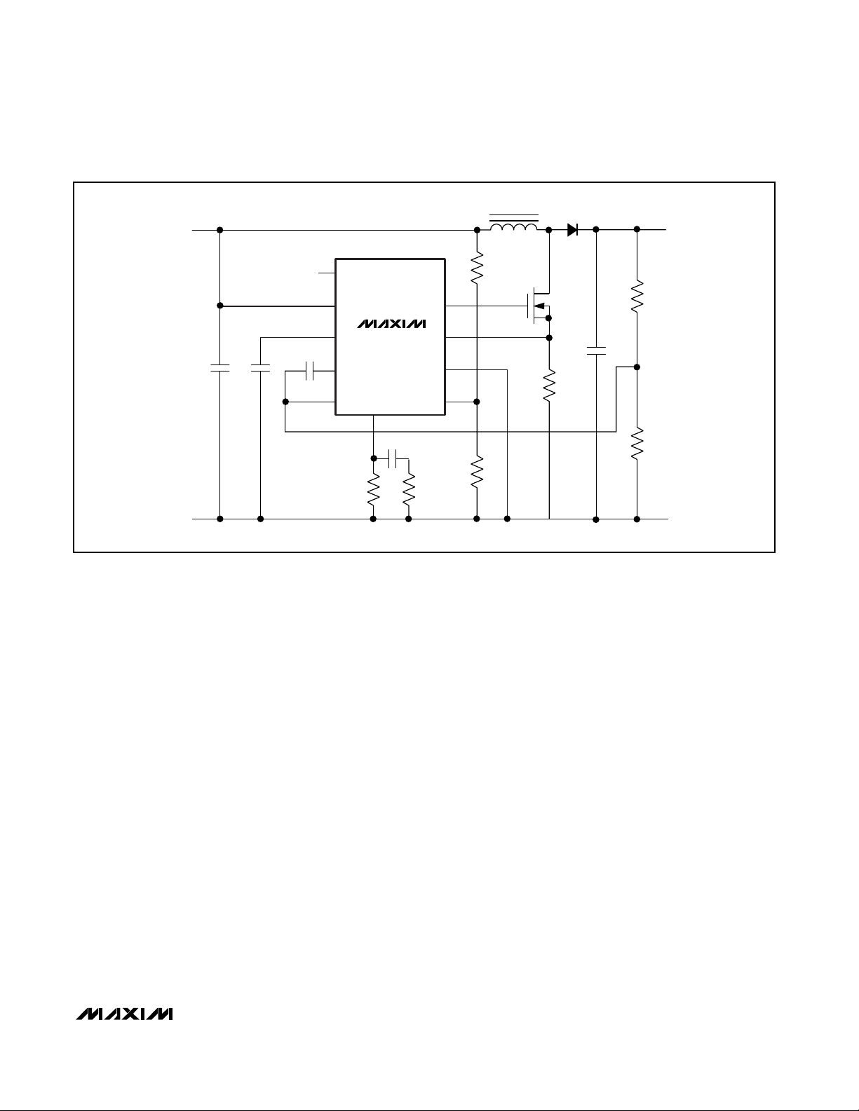
VCC
COMP
FB
GND
CS
NDRV
UVLO/EN
0V
12V
R2
R3
R1
C1
RT
UFLG
C6
R15
R12
C4
IN
MAX15001
C2
C3
R5
R6
15V
D1
Q1
L1
Figure 8. 12V to 15V Output Boost Regulator
Page 16
MAX15000/MAX15001
Current-Mode PWM Controllers with
Programmable Switching Frequency
16 ______________________________________________________________________________________
8
9
10
3
2
1
UVLO/EN
IN
7
4
V
CC
NDRV
GND
UFLG
FB
COMP
6
5
RT
CS
T1
R3
R2
R5
R12
R1
R4
C536V TO 72V
+
-
C2
C2
C1
C4
D2
D1
C6
R11
V
OUT
R15
R6
Q1
MAX15000
Typical Application Circuit
Page 17

MAX15000/MAX15001
Current-Mode PWM Controllers with
Programmable Switching Frequency
______________________________________________________________________________________ 17
Selector Guide
*The MAX15001 does not have an internal bootstrap UVLO. The
MAX15001 starts operation as long as V
IN
is higher than 9.5V
and UVLO/EN is higher than 1.23V.
PART
BOOTSTRAP
UVLO
STARTUP
MAX DUTY
CYCLE (%)
MAX15000A Yes 22 50
MAX15000B Yes 22 75
MAX15001A*
No 9.5 50
MAX15001B*
No 9.5 75
Chip Information
PROCESS: BiCMOS
DRIVER
FB
CS
NDRV
GND
IN
COMP
UVLO/EN
IN
CLAMP
26.1V
*MAX15000 ONLY
*
UFLG
V
CC
MAX15000
MAX15001
ERROR
AMP
CPWM
UVLO
RT
OSCILLATOR
ILIM
S
R
REG_OK
REGULATOR
(INTERNAL 5.25V
SUPPLY)
IN
V
L
V
CC
Q
1.23V
1.17V
V
CS
1V
1.4V
DIGITAL
SOFT-START
REFERENCE
1.23V
N
210µs
DELAY
BOOTSTRAP UVLO
21.6V
9.74V
Functional Diagram
VOLTAGE (V)
Page 18

MAX15000/MAX15001
Current-Mode PWM Controllers with
Programmable Switching Frequency
Maxim cannot assume responsibility for use of any circuitry other than circuitry entirely embodied in a Maxim product. No circuit patent licenses are
implied. Maxim reserves the right to change the circuitry and specifications without notice at any time.
18 ____________________Maxim Integrated Products, 120 San Gabriel Drive, Sunnyvale, CA 94086 408-737-7600
© 2006 Maxim Integrated Products Printed USA is a registered trademark of Maxim Integrated Products, Inc.
Heaney
Package Information
(The package drawing(s) in this data sheet may not reflect the most current specifications. For the latest package outline information,
go to www.maxim-ic.com/packages
.)
10LUMAX.EPS
PACKAGE OUTLINE, 10L uMAX/uSOP
1
1
21-0061
REV.DOCUMENT CONTROL NO.APPROVAL
PROPRIETARY INFORMATION
TITLE:
TOP VIEW
FRONT VIEW
1
0.498 REF
0.0196 REF
S
6°
SIDE VIEW
α
BOTTOM VIEW
0° 0° 6°
0.037 REF
0.0078
MAX
0.006
0.043
0.118
0.120
0.199
0.0275
0.118
0.0106
0.120
0.0197 BSC
INCHES
1
10
L1
0.0035
0.007
e
c
b
0.187
0.0157
0.114
H
L
E2
DIM
0.116
0.114
0.116
0.002
D2
E1
A1
D1
MIN
-A
0.940 REF
0.500 BSC
0.090
0.177
4.75
2.89
0.40
0.200
0.270
5.05
0.70
3.00
MILLIMETERS
0.05
2.89
2.95
2.95
-
MIN
3.00
3.05
0.15
3.05
MAX
1.10
10
0.6±0.1
0.6±0.1
Ø0.50±0.1
H
4X S
e
D2
D1
b
A2
A
E2
E1
L
L1
c
α
GAGE PLANE
A2 0.030 0.037 0.75 0.95
A1
 Loading...