

Page 1
General Description
The MAX14514 is a high-voltage DC-AC converter ideal
for driving two electroluminescent (EL) lamps. The
MAX14514 features a +2.7V to +5.5V input range that
allows the device to accept a wide variety of voltage
sources, including single-cell lithium-ion (Li+) batteries.
The lamp outputs of the device generate up to 300V
P-P
for maximum lamp brightness.
The MAX14514 utilizes an inductor-based boost converter to generate the high voltage necessary to drive EL
lamps and allows the use of a 220µH inductor to effectively drive total combined lamp sizes of up to 20nF.
The MAX14514 uses a high-voltage full-bridge output
stage to convert the high voltage generated by the
boost converter to an AC waveform suitable for driving
the EL panels. An external resistor controls the slewrate of the rising and falling edges of the AC drive
waveform to reduce audible noise output. The high-voltage outputs are ESD protected up to ±15kV Human
Body Model, ±4kV IEC 61000-4-2 Air Gap Discharge,
and ±4kV IEC 61000-4-2 Contact Discharge.
The MAX14514 features dimming/enable controls
(DIM1, DIM2) for each output to allow the user to set
the peak-to-peak output voltage with a PWM signal, a
DC analog voltage, or a resistor connected from DIM_
to GND. The MAX14514 also provides a slow turn-on/off feature that slowly ramps the output voltage applied
to the lamp when enabled or disabled.
The MAX14514 enters a low-power shutdown mode
when the EN and DIM_ inputs are connected to GND.
The device also features thermal shutdown if the die
temperature exceeds +158°C (typ).
The MAX14514 is available in a space-saving, 14-pin,
3mm x 3mm TDFN package and is specified over the
extended -40°C to +85°C operating temperature range.
Applications
Keypad Backlighting
LCD Backlighting
PDAs/Smartphones
Automotive Instrument Clusters
Features
♦ Dual ±15kV ESD-Protected EL Lamp Outputs
♦ 300V
P-P
Maximum Output for Highest Brightness
♦ +2.7V to +5.5V Input Voltage Range
♦ Resistor Adjustable Slew-Rate Control
♦ Resistor Adjustable Lamp and Switching
Converter Frequencies
♦ DIM Input for Controlling Output Voltage Through
DC Analog Voltage, PWM, or Resistor to GND
♦ Capacitor Adjustable Soft Turn-On/-Off
♦ Low 150nA Shutdown Current
♦ Thermal Shutdown
♦ Space Saving, 14-Pin, 3mm x 3mm TDFN Package
MAX14514
Dual Electroluminescent Lamp Driver
________________________________________________________________
Maxim Integrated Products
1
Pin Configuration
19-4466; Rev 0; 2/09
EVALUATION KIT
AVAILABLE
PART TEMP RANGE PIN-PACKAGE
MAX14514ETD+ -40°C to +85°C 14 TDFN-EP*
Ordering Information
+
Denotes a lead(Pb)-free/RoHS-compliant package.
*
EP = Exposed pad.
MAX14514
TDFN-EP
(3mm x 3mm)
+
TOP VIEW
*EP = EXPOSED PAD. CONNECT EP TO GND OR LEAVE UNCONNECTED.
245
13 11 10
EN
V2COM
DIM2
EL
SW
1
14
SLEWDIM1
3
12
V
1
CAP
6
9
CSV
DD
7
8
LXGND
*EP
For information on other Maxim products, visit Maxim’s website at www.maxim-ic.com.
Page 2
MAX14514
Dual Electroluminescent Lamp Driver
2 _______________________________________________________________________________________
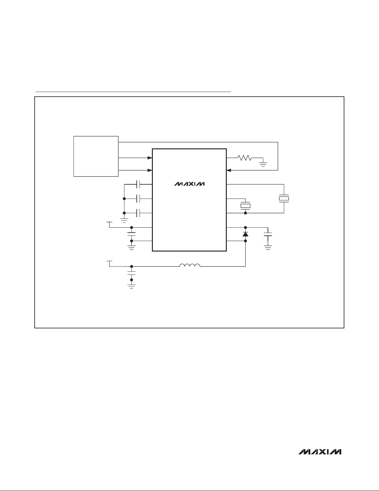
Typical Application Circuit
R
BASEBAND/PMIC
DIM1
SLEW
SLEW
COM
EN
V
1
CCS = 3.3nF
EL LAMP
C
LAMP
= 10nF
2
CS
LX
EL LAMP
C
LAMP
= 10nF
DIM2
C
CAP
CAP
C
EL
EL V
C
SW
V
DD
0.1µF
V
BAT
4.7µF
SW
V
DD
GND
MAX14514
LX = 220µH
Page 3
MAX14514
Dual Electroluminescent Lamp Driver
_______________________________________________________________________________________ 3
ABSOLUTE MAXIMUM RATINGS
ELECTRICAL CHARACTERISTICS
(VDD= +2.7V to +5.5V, C
LAMP_TOTAL
= 10nF, CCS= 3.3nF, LX= 220µH (I
SAT
= 170mA, RS= 5.5Ω), TA= -40°C to +85°C, unless oth-
erwise noted. Typical values are at V
DD
= +3.0V, TA= +25°C.) (Note 2)
Stresses beyond those listed under “Absolute Maximum Ratings” may cause permanent damage to the device. These are stress ratings only, and functional
operation of the device at these or any other conditions beyond those indicated in the operational sections of the specifications is not implied. Exposure to
absolute maximum rating conditions for extended periods may affect device reliability.
Note 1: Package thermal resistances were obtained using the method described in JEDEC specification JESD51-7, using a four-layer
board. For detailed information on package thermal considerations, refer to www.maxim-ic.com/thermal-tutorial
.
(Voltages referenced to GND.)
V
DD
........................................................................-0.3V to +6.0V
CS, LX...................................................................-0.3V to +160V
V
1
, V2, COM................................................-0.3V to (VCS+ 0.3V)
SW, EL, DIM_, SLEW, CAP, EN ..................-0.3V to (V
DD
+ 0.3V)
Continuous Power Dissipation (T
A
= +70°C)
14-Pin TDFN (derate 24.4mW/°C above +70°C) .......1951mW
Junction-to-Case Thermal Resistance (θ
JC
) (Note 1)
14-Pin TDFN...................................................................8°C/W
Junction-to-Ambient Thermal Resistance (θ
JA
) (Note 1)
14-Pin TDFN.................................................................41°C/W
Operating Temperature Range ...........................-40°C to +85°C
Junction Temperature......................................................+150°C
Storage Temperature Range .............................-65°C to +150°C
Lead Temperature (soldering, 10s) .................................+300°C
PARAMETER SYMBOL CONDITIONS MIN TYP MAX UNITS
Input Supply Voltage V
Input Supply Current I
Shutdown Supply Current I
Shutdown Inductor Supply
Current
Undervoltage Lockout V
Undervoltage Lockout Hysteresis V
EL OUTPUTS (V1, V2, COM)
Peak-to-Peak Output Voltage V_ - V
V1, V2 High-Side Switch OnResistance
V1, V2 Low-Side Switch OnResistance
COM High-Side Switch OnResistance
COM Low-Side Switch OnResistance
High-Side Switch Off-Leakage R
Low-Side Switch Off-Leakage R
EL Lamp Switching Frequency f
ESD Protection (COM, V1, V
2
Only)
DD
R
= 375kΩ, FEL = 200Hz,
IN
SHDN
I
LX_SHDN
UV
UV_HYST
COMVDD
R
ONHS_VNISOURCE
R
ONLS_VNISINK
R
ON HS _C OM ISOURCE
R
ON LS _C OM
ON HS _LEAKV1
ON LS _LE AKV1
EL
SLEW
(V1,V2) - V
COM
= 300V
EN = GND
EN = GND, LX = VDD, CS = V
VDD falling 1.8 2.1 2.3 V
= +3V
= 1mA 1.5 3.0 kΩ
= 1mA 0.7 2.0 kΩ
= 1mA 0.7 1.5 kΩ
I
= 1mA 0.4 1.0 kΩ
SINK
, V2, V
, V2, V
CEL = 872pF, R
= 0, VCS = 150V -1 +1 µA
COM
= 150V, VCS = 150V -1 +1 µA
COM
SLEW
Human Body Model ±15
IEC 61000-4-2 Contact Discharge ±4
IEC 61000-4-2 Air-Gap Discharge ±4
2.7 5.5 V
P-P
TA = +25°C 40 150
= - 40°C to + 85°C 400
T
A
DD
700 µA
nA
1.5 µA
125 mV
V
= +0.5V 105 130 162
DIM_
V
= +1V 210 260 310
DIM_
= +1.3V 250 300 350
V
DIM_
= 375kΩ 210 250 290 Hz
kV
V
Page 4
MAX14514
Dual Electroluminescent Lamp Driver
4 _______________________________________________________________________________________
ELECTRICAL CHARACTERISTICS (continued)
(VDD= +2.7V to +5.5V, C
LAMP_TOTAL
= 10nF, CCS= 3.3nF, LX= 220µH (I
SAT
= 170mA, RS= 5.5Ω), TA= -40°C to +85°C, unless
otherwise noted. Typical values are at V
DD
= +3.0V, TA= +25°C.) (Note 2)
PARAMETER SYMBOL CONDITIONS MIN TYP MAX UNITS
BOOST CONVERTER
Boost Switching Frequency f
Switch On-Resistance R
LX Leakage Current I
CS Input Current I
CONTROL INPUT (SW)
Input-Voltage High Threshold V
Input-Voltage Low Threshold V
Input Low Current I
Input High Current I
CONTROL INPUT (EL)
Input-Voltage High Threshold V
Input-Voltage Low Threshold V
Input Low Current I
Input High Current I
CONTROL INPUT (CAP)
CAP Switching Frequency f
Slow Turn-On Time t
Fast Turn-On CAP Threshold V
Nonfast Turn-On CAP Threshold
Input Leakage Current I
CONTROL INPUT (SLEW)
Force Voltage V
High-Voltage Output Slew Rate R
CONTROL INPUTS (DIM1, DIM2)
Input High Voltage V
Input Low Voltage V
Input Low Current I
Input High Current I
PWM Frequency Range 0.2 to 1 MHz
Low-Peak Detector Threshold V
Low-Peak Detector Hysteresis V
CS
SW
LX
CS
IH_CSWRSLEW
IL_CSWRSLEW
IL_CSW
IH_CSW
IH_CELRSLEW
IL_CELRSLEW
IL_CEL
IH_CEL
CAP
SLOW_ONRSLEW
FAST_CAPRSLEW
V
NON-
FAST_CAP
IH_CAP
FORCE
IH_DIM__
IL_DIM__
IL_DIM__VDIM_
IH_DIM__VDIM_
LPD
LPD_HYST
VDD = +3V
LX
CSW = 96pF, R
I
= 25mA, V
SINK
V
= +150V -1 +1 µA
LX
N o l oad , V
C S
= 375kΩ 80 100 120 kHz
SLEW
= +3V 20 Ω
DD
= + 150V , V
= 375kΩ 0.9 0.98 1.06 V
= 375kΩ 0.43 0.49 0.55 V
R
= 375kΩ, VCS = +78V, C
SLEW
V
= V
R
V
DIM_
SLEW
DIM_
DD
= 375kΩ, VCS = +78V, C
= V
DD
= 375kΩ 1.08 1.32 V
= 375kΩ 0.22 0.39 V
R
= 375kΩ 1.3 1.88 µA
SLEW
R
= 375kΩ 1.3 1.88 µA
SLEW
R
= 375kΩ, C
SLEW
= 375kΩ, C
CAP
CAP
= 375kΩ V
R
= 375kΩ 1.4 V
SLEW
CAP = V
DD,
R
SLEW
=
375kΩ
R
= 375kΩ 0.9 0.98 1.05 V
SLEW
= 375kΩ 32 V/100µs
SLEW
Max output voltage 1.3 V
Min output voltage 0.15 V
= 0, R
= V
= 375kΩ 2.2 2.6 3.0 µA
SLEW
DD
V
= +0.5V 52 65 81
DIM_
V
= +1V 105 130 155Output Regulation Voltage V
DIM_
V
= +1.3V 125 150 175
DIM_
E N
= 0, V
= 050µA
D IM _
= V
EL
EL
= V
DD,
DD,
43 79 µA
5 7.5 µA
= 1.25nF 180 300 410 Hz
= 1.25nF 0.3 s
- 0.35 V
D D
Normal operation 0.3 1 µA
Shutdown mode -100 100 nA
-1 +1 µA
0.13 0.35 V
100 mV
V
Page 5
MAX14514
Dual Electroluminescent Lamp Driver
_______________________________________________________________________________________ 5
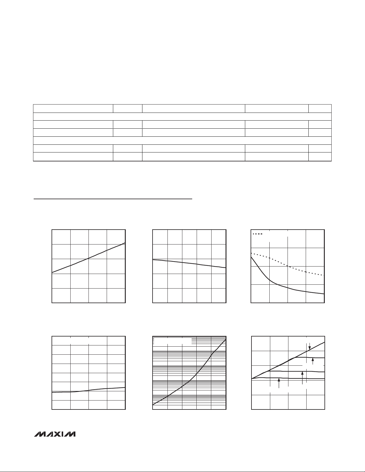
Typical Operating Characteristics
(VDD= +3.6V, TA= +25°C, unless otherwise noted.)
ELECTRICAL CHARACTERISTICS (continued)
(VDD= +2.7V to +5.5V, C
LAMP_TOTAL
= 10nF, CCS= 3.3nF, LX= 220µH (I
SAT
= 170mA, RS= 5.5Ω), TA= -40°C to +85°C, unless
otherwise noted. Typical values are at V
DD
= +3.0V, TA= +25°C.) (Note 2)
Note 2: All devices are 100% production tested at TA= +25°C. All temperature limits are guaranteed by design.
PARAMETER SYMBOL CONDITIONS MIN TYP MAX UNITS
CONTROL INPUT (EN)
Input Logic-High Voltage V
Input Logic-Low Voltage V
IH_EN
IL_EN
1.4 V
0.3 V
THERMAL SHUTDOWN
Thermal Shutdown 158 °C
Thermal Shutdown Hysteresis 8°C
TOTAL INPUT CURRENT
vs. SUPPLY VOLTAGE
25
20
MAX14514 toc01
25
20
TOTAL INPUT CURRENT
vs. TEMPERATURE
INPUT CURRENT AND PEAK-TO-PEAK OUTPUT
VOLTAGE vs. BOOST CONVERTER FREQUENCY
MAX14514 toc02
80
60
PEAK-TO-PEAK OUTPUT
90% DUTY CYCLE
MAX14514 toc03
300
225
15
10
TOTAL INPUT CURRENT (mA)
5
0
2.7 5.5
3.4 4.1 4.8
SUPPLY VOLTAGE (V)
SHUTDOWN CURRENT
vs. SUPPLY VOLTAGE
0.4
DIM1 = DIM2 = EN = 0V
0.35
0.3
0.25
0.2
0.15
SHUTDOWN CURRENT (nA)
0.1
0.05
0
2.7 5.5
3.4 4.1 4.8
SUPPLY VOLTAGE (V)
15
10
TOTAL INPUT CURRENT (mA)
5
0
-40 85
100
MAX14514 toc04
10
1
0.1
SHUTDOWN CURRENT (nA)
0.01
0.001
-40 85
TEMPERATURE (°C)
SHUTDOWN CURRENT
vs. TEMPERATURE
DIM1 = DIM2 = EN = 0V
TEMPERATURE (°C)
40
20
TOTAL INPUT CURRENT (mA)
35 60-15 10
0
40 200
80 120 160
BOOST CONVERTER FREQUENCY (kHz)
150
75
PEAK-TO-PEAK OUTPUT VOLTAGE (V)
0
PEAK-TO-PEAK OUTPUT VOLTAGE
vs. SUPPLY VOLTAGE
250
MAX14514 toc05
200
150
100
50
PEAK-TO-PEAK OUTPUT VOLTAGE (V)
0
35 60-15 10
2.7 5.5
DIM_ = 0.4V
3.4 4.1 4.8
SUPPLY VOLTAGE (V)
DIM = 1V
MAX14514 toc06
DIM_ = 0.7V
DIM = 0.5V
Page 6

MAX14514
Dual Electroluminescent Lamp Driver
6 _______________________________________________________________________________________
Typical Operating Characteristics (continued)
(VDD= +3.6V, TA= +25°C, unless otherwise noted.)
PEAK-TO-PEAK OUTPUT VOLTAGE
vs. TEMPERATURE
MAX14514 toc07
TEMPERATURE (°C)
PEAK-TO-PEAK OUTPUT VOLTAGE (V)
35 60-15 10
50
100
150
200
250
0
-40 85
RMS OUTPUT VOLTAGE
vs. SUPPLY VOLTAGE
MAX14514 toc10
SUPPLY VOLTAGE (V)
RMS OUTPUT VOLTAGE (V)
3.4 4.1 4.8
10
30
50
70
20
40
60
80
90
0
2.7 5.5
AVERAGE OUTPUT VOLTAGE
vs. SUPPLY VOLTAGE
MAX14514 toc11
SUPPLY VOLTAGE (V)
AVERAGE OUTPUT VOLTAGE (mV)
3.4 4.1 4.8
100
300
500
200
400
600
700
0
2.7 5.5
AVERAGE OUTPUT VOLTAGE
vs. TEMPERATURE
MAX14514 toc12
TEMPERATURE (°C)
AVERAGE OUTPUT VOLTAGE (mV)
35 60-15 10
100
300
500
200
400
600
700
0
-40 85
EL SWITCHING FREQUENCY vs. C
EL
MAX14514 toc13
CEL (nF)
EL SWITCHING FREQUENCY (Hz)
1 1.5 2
100
300
500
200
400
600
0
0.5 2.5
EL SWITCHING FREQUENCY
vs. SUPPLY VOLTAGE
MAX14514 toc14
SUPPLY VOLTAGE (V)
EL SWITCHING FREQUENCY (Hz)
3.4 4.1 4.8
226
228
230
227
229
231
233
232
234
235
225
2.7 5.5
EL SWITCHING FREQUENCY
vs. TEMPERATURE
MAX14514 toc15
TEMPERATURE (°C)
EL SWITCHING FREQUENCY (Hz)
35-15 6010
190
210
230
200
220
240
260
250
270
180
-40 85
PEAK-TO-PEAK OUTPUT VOLTAGE
vs. DIM VOLTAGE
250
DIM1 = DIM2
200
150
100
50
PEAK-TO-PEAK OUTPUT VOLTAGE (V)
0
0.35 0.85
DIM VOLTAGE (V)
VDD = 5.5V
VDD = 4.6V
VDD = 3.6V
VDD = 2.7V
1.35
PEAK-TO-PEAK OUTPUT VOLTAGE
250
DIM1 = DIM2
= 5.5V
V
MAX14514 toc08
DD
200
150
100
50
PEAK-TO-PEAK OUTPUT VOLTAGE (V)
0
20 80
vs. DIM DUTY CYCLE
f
= 1MHz
DIM
f
6040
DUTY CYCLE (%)
DIM
MAX14514 toc09
= 200kHz
Page 7

MAX14514
Dual Electroluminescent Lamp Driver
_______________________________________________________________________________________ 7
Typical Operating Characteristics (continued)
(VDD= +3.6V, TA= +25°C, unless otherwise noted.)
BOOST CONVERTER FREQUENCY vs. C
140
120
100
80
60
40
BOOST CONVERTER FREQUENCY (Hz)
20
0
80
130 180
CSW (pF)
OUTPUT VOLTAGE SLOPE vs. R
45
40
35
30
25
20
15
OUTPUT VOLTAGE SLOPE (V/100μs)
10
5
300 1000
500 700400 800 900600
R
SLEW
(kΩ)
SLEW
SW
130
128
126
MAX14514 toc16
124
122
120
118
116
114
BOOST CONVERTER FREQUENCY (kHz)
112
110
MAX14514 toc19
OUTPUT VOLTAGE SLOPE (V/100μs)
BOOST CONVERTER FREQUENCY
vs. SUPPLY VOLTAGE
2.7 5.5
3.4 4.1 4.8
SUPPLY VOLTAGE (V)
OUTPUT VOLTAGE SLOPE
vs. SUPPLY VOLTAGE
36
35
34
33
32
31
30
29
28
27
26
2.7 5.5
3.4 4.1 4.8
SUPPLY VOLTAGE (V)
BOOST CONVERTER FREQUENCY
130
128
126
MAX14514 toc17
124
122
120
118
116
114
BOOST CONVERTER FREQUENCY (kHz)
112
110
-40 85
OUTPUT VOLTAGE SLOPE
36
35
MAX14514 toc20
34
33
32
31
30
29
28
OUTPUT VOLTAGE SLOPE (V/100μs)
27
26
-40 85
vs. TEMPERATURE
MAX14514 toc18
35 60-15 10
TEMPERATURE (°C)
vs. TEMPERATURE
MAX14514 toc21
35 60-15 10
TEMPERATURE (°C)
NORMALIZED BRIGHTNESS LEVEL
SLOW TURN-ON/TURN-OFF TIME vs. C
1
VDD = 5.5V
0.9
DIM1 = 0V to V
DIM2 = GND
0.8
0.7
0.6
0.5
0.4
0.3
0.2
SLOW TURN-ON/TURN-OFF TIME (s)
0.1
0
010
DD
6824
C
(nF)
CAP
CAP
2
1.8
1.6
MAX14514 toc22
1.4
1.2
1
0.8
0.6
0.4
NORMALIZED BRIGHTNESS LEVEL
0.2
0
2.7 5.5
vs. SUPPLY VOLTAGE
3.4 4.1 4.8
SUPPLY VOLTAGE
MAX14514 toc23
TYPICAL V_, V
V_ - V
WAVEFORMS
COM
1ms/div
COM
, AND
MAX14514 toc24
V_ - V
50V/div
V_, V
25V/div
COM
COM
Page 8

MAX14514
Dual Electroluminescent Lamp Driver
8 _______________________________________________________________________________________
Pin Description
PIN NAME FUNCTION
High-Voltage Output 1 Dimming Control. Apply a PWM signal, DC analog control signal, or connect a
1DIM1
2DIM2
3 CAP
4EL
5SW
6VDDInput Supply Voltage
7 GND Ground
8LX
9CSH i g h- V ol tag e Feed b ack C onnecti on. C onnect C S to outp ut of b oost conver ter ( cathod e of r ecti fyi ng d i od e) .
10 COM High-Voltage EL Panel Common Output. Connect COM to common side of EL lamp.
11 V
12 V
13 EN
14 SLEW
⎯ EP Exposed Pad. Connect EP to GND.
2
1
resistor from DIM1 to GND to adjust V
unconnected to set V
High-Voltage Output 2 Dimming Control. Apply a PWM signal, DC analog control signal, or connect a
resistor from DIM2 to GND to adjust V
unconnected to set V
Turn-On Time Input. For fast turn-on mode, connect CAP to V
capacitor from CAP to GND to set the turn-on/-off time. t
EL Voltage Switching Frequency. Connect an external capacitor, C
an external oscillator to set the switching frequency of the V
to GND to shut off the EL oscillator.
Boost Converter Switching Frequency. Connect an external capacitor, C
with an external oscillator to set the switching frequency of the boost converter. Connect SW to GND to
shut off the boost oscillator. To avoid LX shorting to GND and causing an increase in internal die
temperature, do not keep SW high. The MAX14514 is protected by entering a thermal-shutdown state.
(See the Thermal Short-Circuit Protection section.)
Internal Switching DMOS Drain Connection. Connect LX to a switching inductor and an anode of a
rectifying diode.
High-Voltage EL Panel Output 2. Connect V2 to non-COM side of EL lamp 2.
High-Voltage EL Panel Output 1. Connect V1 to non-COM side of EL lamp 1.
Enable Input. Drive EN > V
Shutdown section).
High-Voltage Slew-Rate Control. Connect an external resistor, R
slew rate of the high-voltage outputs V
to full brightness level.
1
to full brightness level.
2
IH_EN
peak-to-peak output voltage. Drive DIM1 high or leave DIM1
1
peak-to-peak output voltage. Drive DIM2 high or leave DIM2
2
. For slow turn-on/-off mode, connect a
DD
= 0.27 x C
ON/OFF
and V2 high-voltage outputs. Connect EL
1
to turn on the device. Drive EN < V
and V2.
1
SLEW
x R
CAP
, from EL to GND or drive EL with
EL
from SW to GND or drive
SW,
to turn off the device (see the
IL_EN
, from SLEW to GND to set the
SLEW
.
Page 9

MAX14514
Dual Electroluminescent Lamp Driver
_______________________________________________________________________________________ 9
Functional Diagram
V
SW
SLEW
DD
SWITCH
OSCILLATOR
EL
EL
EL
OSCILLATOR
V-I
CONVERTER
LOW-POWER
SHUTDOWN
REF
V
SENSE
HIGH ESD
PROTECTION
N
LX
CS
V
1
DIM1
DIM2
CAP
GND
PWM
CONVERTER
THERMAL
SHUTDOWN
UVLO
LOW PEAK
DETECTOR
LOW-POWER
SHUTDOWN
DMOS
DRIVER
H-BRIDGE
NO-OPERATION
SIGNAL
MAX14514
HIGH ESD
PROTECTION
HIGH ESD
PROTECTION
V
2
COM
Page 10

MAX14514
Detailed Description
The MAX14514 high-voltage DC-AC converter is
designed to drive two EL lamps. The MAX14514 features a +2.7V to 5.5V input range that allows the device
to accept a wide variety of voltage sources, including
single-cell Li+ batteries. The lamp outputs of the device
generate up to 300V
P-P
for maximum lamp brightness.
The slew rate, frequency, and peak-to-peak voltage of
the MAX14514 EL lamp outputs are programmed
through a combination of external components and/or
logic inputs.
Output Slew Rate
The MAX14514 uses the resistor R
SLEW
to set a reference current for the internal circuitry. The reference
current directly affects the slew rate of the EL lamp output. Increasing the value of R
SLEW
decreases the slew
rate, and decreasing the value of R
SLEW
increases the
slew rate. (See the
R
SLEW
Resistor Selection
section on
how to select R
SLEW
.)
Output Frequency
The MAX14514 uses an internal oscillator to set the
desired output frequency. The output frequency is
adjusted by either 1) the combination of a resistor from
SLEW to GND and an external capacitor from the EL
input to GND, or 2) by driving a clock signal directly
into the EL input. (See the
CELCapacitor Selection
sec-
tion for choosing the CELcapacitor value.)
Dimming Control
The MAX14514 features dimming control inputs, DIM1
and DIM2, to control the peak-to-peak voltages on lamp
outputs V1, V2, and COM. DIM_ is controlled by either a
DC voltage, a PWM signal, or a resistor from DIM_ to
GND. (See the
R
DIM
Resistor Selection
section.)
Applying a DC voltage to DIM_ ranging from V
LPD
to
V
IH_DIM_
linearly varies the corresponding output voltage from 130V to 300V. Increasing the voltage on DIM_
increases the peak-to-peak output, and decreasing the
voltage on DIM_ decreases the peak-to-peak output
voltage. Note that when V
DIM_
goes below V
IL_DIM_
, the
corresponding output turns off.
DIM_ features an internal lowpass filter to allow a PWM
signal to control the output voltage. Voltages on DIM_
are internally level translated down to V
IH_DIM_
, so that
the equivalent voltage on DIM_ is (%duty cycle) x
V
IH_DIM_
. The DIM_ inputs accept the 200kHz to 1MHz
frequency range. Note that for PWM signals, the logic
voltage applied to DIM__must be greater than or equal
to V
IH_DIM_
.
The peak-to-peak EL lamp output voltage is related to
V
DIM_
(for V
DIM_
> V
IL_DIM_
) or PWM duty cycle by the
following equation:
V_ - V
COM
= 260 x (V
DIM_
) = 260 x (%duty cycle) x
(V
IH_DIM_
)
Slow Turn-On, Slow Turn-Off
The MAX14514 provides a slow turn-on and slow turnoff time feature that is enabled by connecting a capacitor from CAP to GND (see the
Typical Application
Circuit
and the
C
CAP
Capacitor Selection
section). This
slow turn-on/-off feature causes the peak-to-peak voltage of the EL outputs to slowly rise or fall any time the
outputs are enabled or disabled, either through EN or
DIM_ (see Table 1). The slow rise and fall of the peakto-peak EL output voltage creates a soft fade-on and
fade-off of the EL lamp, rather than an abrupt change in
brightness. To disable the slow turn-on/turn-off feature,
connect CAP to VDD.
Boost Converter
The MAX14514 boost converter consists of an external
inductor from VDDto the LX input, an internal DMOS
switch, an external diode from LX to the CS output, an
external capacitor from the CS output to GND, and the
EL lamps, C
LAMP1
and C
LAMP2
, connected to the EL
lamp outputs. When the DMOS switch is turned on, LX
is connected to GND, and the inductor is charged.
When the DMOS switch is turned off, the energy stored
in the inductor is transferred to the capacitor CCSand
the EL lamps.
Note: Keeping SW high shorts LX to GND and causes
the internal die temperature to increase. The MAX14514
is protected by entering a thermal-shutdown state (see
the
Thermal Short-Circuit Protection
section).
Dual Electroluminescent Lamp Driver
10 ______________________________________________________________________________________
Table 1. Slow Turn-On, Slow Turn-Off
*
With capacitor from CAP to GND (CAP is not connected to VDD).
X = Don’t Care.
LOGIC INPUT EL OUTPUTS*
EN DIM1 DIM2 V
1 ≥ 0 1 1 Slow Turn-Off Slow Turn-Off
0 ≥ 1 1 1 Slow Turn-On Slow Turn-On
11 ≥ 0 X Slow Turn-Off X
10 ≥ 1 X Slow Turn-On X
1X1 ≥ 0 X Slow Turn-Off
1X0 ≥ 1 X Slow Turn-On
1
V
2
Page 11

The MAX14514 boost converter frequency uses an
internal switch oscillator to set the desired frequency of
the boost converter. The boost converter frequency is
adjusted by either 1) the combination of a resistor from
SLEW to GND and an external capacitor from SW to
GND, or 2) by driving a PWM signal directly into the SW
input. When SW is driven with an external PWM signal
at a suggested 90% duty cycle, the boost converter frequency is changed to the frequency of the external
PWM signal. (See the
CSWCapacitor Selection
section
for choosing the C
SW
capacitor value.)
Shutdown
The MAX14514 features a shutdown mode to disable
the device and reduce supply current. Entering and
exiting shutdown mode depends on if slow turn-on/turnoff is enabled or disabled.
When slow turn-on/turn-off is enabled, shut down the
device by driving EN low. Enable the device by driving
EN high.
When slow turn-on/turn-off is disabled, shut down the
device by driving EN low and both DIM1 and DIM2
below V
IL_DIM_
. Enable the device by driving EN high
and either DIM1 or DIM2 above V
LPD_
.
Undervoltage Lockout (UVLO)
The MAX14514 has a UVLO threshold of +2.1V (typ).
When VDDfalls below this threshold, the device enters
a nonoperative mode.
Thermal Short-Circuit Protection
The MAX14514 enters a nonoperative mode if the
internal die temperature of the device reaches or
exceeds +158°C (typ). The device turns back on when
the internal die temperature cools to +150°C (typ).
±15kV ESD Protection
As with all Maxim devices, ESD-protection structures
are incorporated on all pins to protect against electrostatic discharges encountered during handling and
assembly. The EL lamp driver outputs of the MAX14514
(V1, V2, and COM) have extra protection against static
electricity. Maxim’s engineers have developed state-ofthe-art structures to protect these pins against ESD of
±15kV without damage. The ESD structures withstand
high ESD in all states: normal operation, shutdown, and
powered down. After an ESD event, the MAX14514
keeps working without latchup or damage.
ESD protection can be tested in various ways. The
transmitter EL lamp outputs of the MAX14514 are characterized for protection to the following limits:
• ±15kV using the Human Body Model
• ±4kV IEC 61000-4-2 Contact Discharge
• ±4kV IEC 61000-4-2 Air-Gap Discharge
ESD Test Conditions
ESD performance depends on a variety of conditions.
Contact Maxim for a reliability report that documents
test setup, test methodology, and test results.
Human Body Model
Figure 1a shows the Human Body Model, and Figure
1b shows the current waveform it generates when discharged into a low impedance. This model consists of a
100pF capacitor charged to the ESD voltage of interest,
which is then discharged into the test device through a
1.5kΩ resistor.
IEC 61000-4-2
The IEC 61000-4-2 standard covers ESD testing and
performance of finished equipment. However, it does
not specifically refer to integrated circuits. The
MAX14514 assists in designing equipment to meet IEC
61000-4-2 without the need for additional ESD-protection components.
The major difference between tests done using the
Human Body Model and IEC 61000-4-2 is higher peak
current in IEC 61000-4-2 because series resistance is
lower in the IEC 61000-4-2 model. Hence, the ESD withstand voltage measured to IEC 61000-4-2 is generally
lower than that measured using the Human Body
Model. Figure 1c shows the IEC 61000-4-2 model, and
Figure 1d shows the current waveform for IEC 61000-4-2
ESD Contact Discharge test.
The air-gap test involves approaching the device with
a charged probe. The contact discharge method connects the probe to the device before the probe is
energized.
MAX14514
Dual Electroluminescent Lamp Driver
______________________________________________________________________________________ 11
Page 12

MAX14514
Design Procedure
LX Inductor Selection
The recommended inductor values are 220µH/330µH.
For most applications, series resistance (DCR) should
be below 8Ω for reasonable efficiency. Do not exceed
the inductor’s saturation current.
Dual Electroluminescent Lamp Driver
12 ______________________________________________________________________________________
Figure 1a. Human Body ESD Test Model
Figure 1b. Human Body Current Waveform
Figure 1c. IEC 61000-4-2 ESD Test Model
Figure 1d. IEC 61000-4-2 ESD Generator Current Waveform
Table 2. Inductor Vendors
R
C
1MΩ
R
D
1500Ω
R
C
50MΩ TO 100MΩ
330Ω
R
D
DISCHARGE
RESISTANCE
STORAGE
C
s
CAPACITOR
HIGH-
VOLTAGE
DC
SOURCE
CHARGE-CURRENT-
LIMIT RESISTOR
100pF
IP 100%
90%
AMPS
36.8%
10%
0
0
t
RL
TIME
CURRENT WAVEFORM
I
r
t
DL
DEVICE
UNDER
TEST
PEAK-TO-PEAK RINGING
(NOT DRAWN TO SCALE)
DISCHARGE
RESISTANCE
STORAGE
C
s
CAPACITOR
DEVICE
UNDER
TEST
HIGH-
VOLTAGE
DC
SOURCE
CHARGE-CURRENT-
LIMIT RESISTOR
150pF
I
100%
90%
PEAK
I
10%
tr = 0.7ns TO 1ns
30ns
60ns
t
INDUCTOR VALUE (µH) VENDOR WEBSITE PART
220 TOKO www.tokoam.com D312C 1001BS-221M
330 Coilcraft www.coilcraft.com DO1608C-334ML
470 Coilcraft www.coilcraft.com DO1608C-474ML
220 Coilcraft www.coilcraft.com LPS4018-224ML
330 Coilcraft www.coilcraft.com LPS4018-334ML
470 Coilcraft www.coilcraft.com LPS4018-474ML
220 Cooper Bussmann www.cooperet.com SDH3812-221-R
220 Cooper Bussmann www.cooperet.com SD3110-221-R
Page 13

R
SLEW
Resistor Selection
To help reduce audible noise emission by the EL
lamps, the MAX14514 features a slew-rate control
input (SLEW) that allows the user to set the slew rate of
high-voltage outputs, V1, V2, and COM, by connecting
a resistor, R
SLEW
, from the SLEW input to GND.
Decreasing the value of R
SLEW
increases the slew rate
at the EL lamp output. Increasing the value of R
SLEW
decreases the slew rate at the EL lamp outputs. The
output slew rate is related to R
SLEW
by the following
equation:
SlewRate(V/100µs) = 12/R
SLEW
(MΩ)
The ideal value for a given design varies depending on
lamp size and mechanical enclosure. Typically, the
best slew rate for minimizing audible noise is between
10V/100µs and 20V/100µs. This results in R
SLEW
values
ranging from 1.2MΩ to 600kΩ. For example, if the
desired slew rate is 20(V/100µs), this leads to an R
SLEW
value of 12/20(V/100µs) = 600kΩ.
Note: Connecting R
SLEW
to GND does not damage the
device. However, for the device to operate correctly,
R
SLEW
should be in the 100kΩ to 2.2MΩ range. R
SLEW
also affects the frequency of the boost converter (see
the
CSWCapacitor Selection
section), the frequency of
the EL lamp (see the
CELCapacitor Selection
section),
and the peak-to-peak voltage of the EL lamp.
C
CAP
Capacitor Selection
The MAX14514 provides a slow turn-on/-off feature that
is enabled by connecting a capacitor from CAP to
GND. For fast turn-on/-off, connect CAP to VDD. Slow
turn-on/-off time is related by the following equation:
t
ON/OFF
= 0.27 x C
CAP
x R
SLEW
R
DIM
Resistor Selection
The MAX14514 features dimming control inputs, DIM1
and DIM2, to control the peak-to-peak voltages on the
lamp outputs V1, V2, and COM. DIM_ is controlled by a
PWM signal, DC voltage, or by a resistor connected
from DIM_ to GND. When using a resistor, the output
voltage is related by the following equation:
V_ - V
COM
= 260 x R
DIM/RSLEW
CCSCapacitor Selection
CCSis the output of the boost converter and provides
the high-voltage source for the EL lamp. Connect a
3.3nF capacitor from CS to GND and place as close to
the CS input as possible. When using an inductor value
larger than 220µH, it may be necessary to increase
C
CS
. For a 470µH inductor and C
LAMP_TOTAL
= 20nF, a
CCSranging from 3.3nF to 6.8nF is recommended.
CELCapacitor Selection
The MAX14514 EL lamp output frequency is set by connecting a capacitor from the EL input to GND together
with a resistor from SLEW to GND or by driving the EL
input with an external clock. The EL lamp output frequency is related to the CELcapacitor by the following
equation:
f
EL
= 0.08175/(R
SLEW
x CEL)
For example, an R
SLEW
= 375kΩ and a CELcapacitor
value of 872pF equals an EL lamp output frequency of
fEL= 250Hz.
CSWCapacitor Selection
The boost converter switching frequency is set by connecting a capacitor from the SW input to GND, together
with the resistance from the SLEW input to GND, or driving the SW input with an external clock (0 to +1.5V).
The switching frequency of the boost converter is related to the capacitor from SW to GND by the following
equation:
fSW= 3.6/(R
SLEW
x CSW)
Connect the SW input to GND to turn the switch oscillator of the boost converter off. Although the optimal f
SW
depends on the inductor value, the suggested f
SW
range is 20kHz to 150kHz.
Note: Driving SW with a logic-high causes LX to be driven to GND. Keeping SW high shorts LX to GND, causing the internal die temperature to increase. The
MAX14514 is protected by entering a thermal-shutdown
state. (See the
Thermal Short-Circuit Protection
section.)
Bypass Capacitor Selection
Bypass VDDwith a 0.1µF ceramic capacitor as close to
the IC as possible and a 4.7µF ceramic capacitor as
close to the inductor as possible.
Diode Selection
Connect a diode, D1, from the LX node to CS to rectify
the boost voltage on CS. The diode should be a fastrecovery diode that is tolerant to +150V.
EL Lamp Selection
EL lamps have a capacitance of approximately 2.5nF to
3.5nF per square inch. The MAX14514 effectively
charges capacitance ranging from 2nF to 20nF.
MAX14514
Dual Electroluminescent Lamp Driver
______________________________________________________________________________________ 13
Page 14

MAX14514
Dual Electroluminescent Lamp Driver
Maxim cannot assume responsibility for use of any circuitry other than circuitry entirely embodied in a Maxim product. No circuit patent licenses are
implied. Maxim reserves the right to change the circuitry and specifications without notice at any time.
14
____________________Maxim Integrated Products, 120 San Gabriel Drive, Sunnyvale, CA 94086 408-737-7600
© 2009 Maxim Integrated Products Maxim is a registered trademark of Maxim Integrated Products, Inc.
Applications Information
PCB Layout
Keep PCB traces as short as possible. Ensure that
bypass capacitors are as close to the device as possible. Use large ground planes where possible.
Chip Information
PROCESS: BiCMOS-DMOS
PACKAGE TYPE PACKAGE CODE DOCUMENT NO.
14 TDFN-EP T1433-2
21-0137
Package Information
For the latest package outline information and land patterns, go to www.maxim-ic.com/packages.
 Loading...