

Page 1
July 1999
LM50
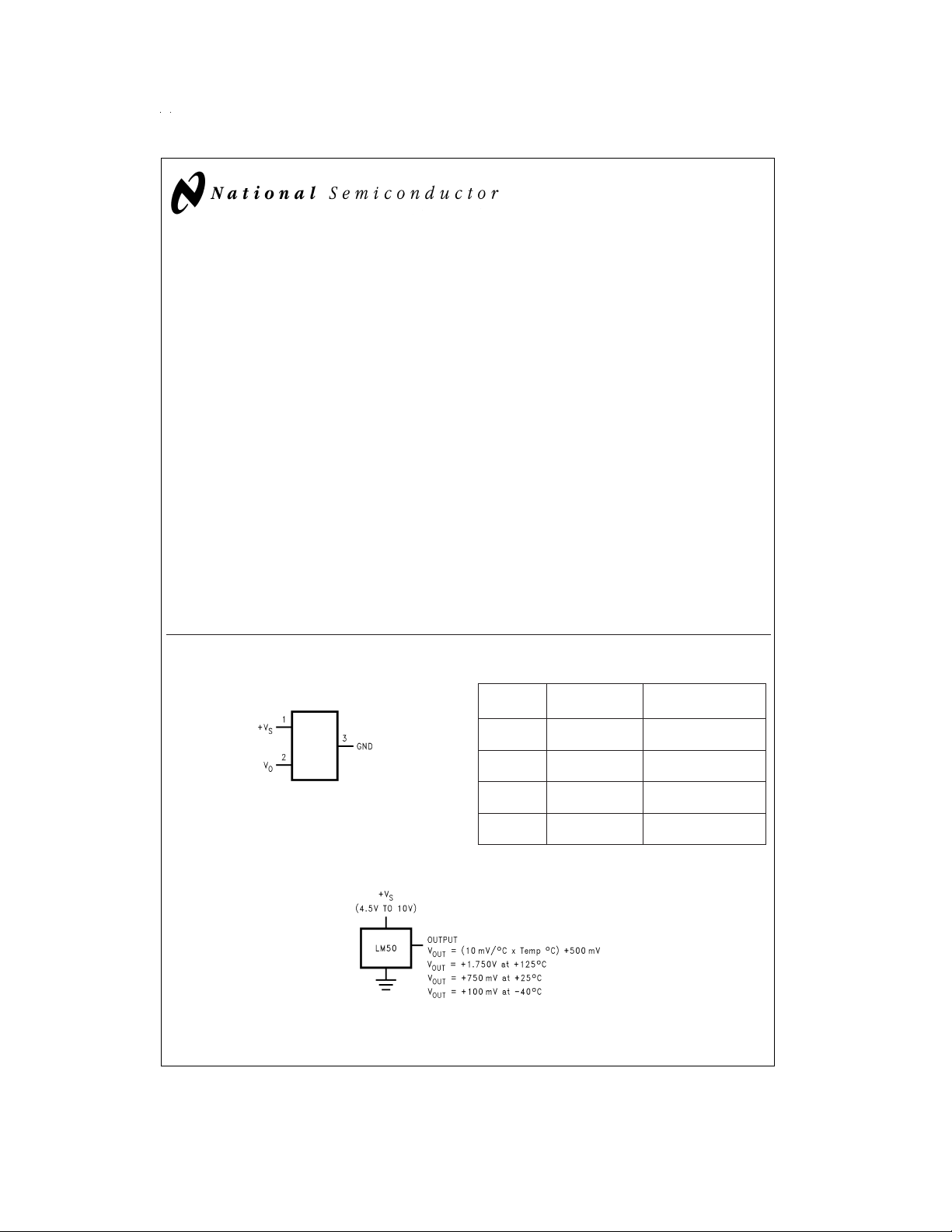
SOT-23 Single-Supply Centigrade Temperature Sensor
LM50 SOT-23 Single-Supply Centigrade Temperature Sensor
General Description
The LM50 is a precision integrated-circuit temperature sensor thatcan sense a −40˚C to +125˚C temperature range using asingle positive supply. The LM50’s outputvoltage is linearly proportional to Celsius (Centigrade) temperature
(+10 mV/˚C) and has a DC offset of +500 mV. The offset allows reading negative temperatures without the need for a
negative supply. The idealoutput voltageof theLM50 ranges
from +100 mV to +1.75V for a −40˚C to +125˚C temperature
range. The LM50 does not requireany externalcalibration or
trimming toprovide accuracies of
±
and
4˚C over the full −40˚C to +125˚C temperature range.
Trimming and calibration of the LM50 at the wafer level assure low cost and high accuracy. The LM50’s linear output,
+500 mV offset, and factory calibration simplify circuitry required in a single supply environment where reading negative temperatures is required. Because the LM50’squiescent
current is less than 130 µA, self-heating is limited to a very
low 0.2˚C in still air.
±
3˚C atroom temperature
Connection Diagram
SOT-23
DS012030-1
See NS Package Number MA03B
Top View
Applications
n Computers
n Disk Drives
n Battery Management
n Automotive
n FAX Machines
n Printers
n Portable Medical Instruments
n HVAC
n Power Supply Modules
Features
n Calibrated directly in degree Celsius (Centigrade)
n Linear + 10.0 mV/˚C scale factor
±
n
2˚C accuracy guaranteed at +25˚C
n Specified for full −40˚ to +125˚C range
n Suitable for remote applications
n Low cost due to wafer-level trimming
n Operates from 4.5V to 10V
n Less than 130 µA current drain
n Low self-heating, less than 0.2˚C in still air
n Nonlinearity less than 0.8˚C over temp
Order SOT-23 Supplied As
Number Device Marking
LM50BIM3 T5B 1000 Units on Tape
LM50CIM3 T5C 1000 Units on Tape
LM50BIM3X T5B 3000 Units on Tape
LM50CIM3X T5C 3000 Units on Tape
and Reel
and Reel
and Reel
and Reel
Typical Application
DS012030-3
FIGURE 1. Full-Range Centigrade Temperature Sensor (−40˚C to +125˚C)
© 1999 National Semiconductor Corporation DS012030 www.national.com
Page 2

Absolute Maximum Ratings (Note 1)
Supply Voltage +12V to −0.2V
Output Voltage (+V
Output Current 10 mA
Storage Temperature −65˚C to +150˚C
Lead Temperature:
SOT Package (Note 2):
Vapor Phase (60 seconds) 215˚C
Infrared (15 seconds) 220˚C
, Maximum
T
JMAX
Junction Temperature 150˚C
+ 0.6V) to −1.0V
S
ESD Susceptibility (Note 3):
Human Body Model
Machine Model
2000V
250V
Operating Ratings (Note 1)
Specified Temperature Range: T
LM50C −40˚C to +125˚C
LM50B −25˚C to +100˚C
Operating Temperature Range −40˚C to +150˚C
(Note 4) 450˚C/W
θ
JA
Supply Voltage Range (+V
) +4.5V to +10V
S
MIN
to T
MAX
Electrical Characteristics
Unless otherwise noted, these specifications apply for V
limits apply for the specified T
=
=
T
A
to T
T
J
MIN
=
+5 V
S
; all other limits T
MAX
and I
DC
Parameter Conditions LM50B LM50C Units
Typical Limit Typical Limit
=
Accuracy T
(Note 6) T
+25˚C
A
=
T
A
MAX
=
T
T
A
MIN
Nonlinearity (Note 7)
Sensor Gain +9.7 +9.7 mV/˚C (min)
(Average Slope) +10.3 +10.3 mV/˚C (max)
Output Resistance 2000 4000 2000 4000 Ω (max)
Line Regulation +4.5V ≤ V
≤ +10V
S
(Note 8)
Quiescent Current +4.5V ≤ V
≤ +10V 130 130 µA (max)
S
(Note 9) 180 180 µA (max)
Change of Quiescent +4.5V ≤ V
≤ +10V 2.0 2.0 µA (max)
S
Current (Note 9)
Temperature Coefficient of +1.0 +2.0 µA/˚C
Quiescent Current
Long Term Stability (Note 10) T
=
J
125˚C, for
±
0.08
1000 hours
Note 1: Absolute Maximum Ratingsindicate limits beyondwhich damage tothe device may occur. DC andACelectrical specifications do not apply when operating
the device beyond its rated operating conditions.
Note 2: See AN-450 “SurfaceMounting Methods and Their Effect on Product Reliability” orthe section titled “Surface Mount” found in a current National Semiconductor Linear Data Book for other methods of soldering surface mount devices.
Note 3: Human body model, 100 pF discharged through a 1.5 kΩ resistor. Machine model, 200 pF discharged directly into each pin.
Note 4: Thermal resistance of the SOT-23 package is specified without a heat sink, junction to ambient.
Note 5: Limits are guaranteed to National’s AOQL(Average Outgoing Quality Level).
Note 6: Accuracy is defined as theerror between the output voltageand 10mv/˚C times the device’s case temperatureplus 500 mV, atspecified conditions of volt-
age, current, and temperature (expressed in ˚C).
Note 7: Nonlinearity is defined as the deviation of the output-voltage-versus-temperature curve from the best-fit straight line, over the device’s rated temperature
range.
Note 8: Regulation is measured at constant junction temperature, using pulse testing with a low duty cycle. Changes in output due to heating effects can be com-
puted by multiplying the internal dissipation by the thermal resistance.
Note 9: Quiescent current is defined in the circuit of
Note 10: For best long-term stability, any precision circuit will give best results if the unit is aged at a warm temperature, and/or temperature cycled for at least 46
hours before long-term life test begins. This is especially true when a small (Surface-Mount)part is wave-soldered;allow time for stress relaxation to occur. The majority of the drift will occur in the first 1000 hours at elevated temperatures. The drift after 1000 hours will not continue at the first 1000 hour rate.
Figure 1
.
=
+0.5 µA, in the circuit of
LOAD
=
=
T
+25˚C, unless otherwise noted.
A
J
(Note 5) (Note 5)
±
2.0
±
3.0
+3.0, −3.5
±
0.8
±
0.8
±
1.2
±
0.08 ˚C
±
±
±
±
±
±
Figure 1
. Boldface
(Limit)
3.0 ˚C (max)
4.0 ˚C (max)
4.0 ˚C (max)
0.8 ˚C (max)
0.8 mV/V (max)
1.2 mV/V (max)
www.national.com 2
Page 3
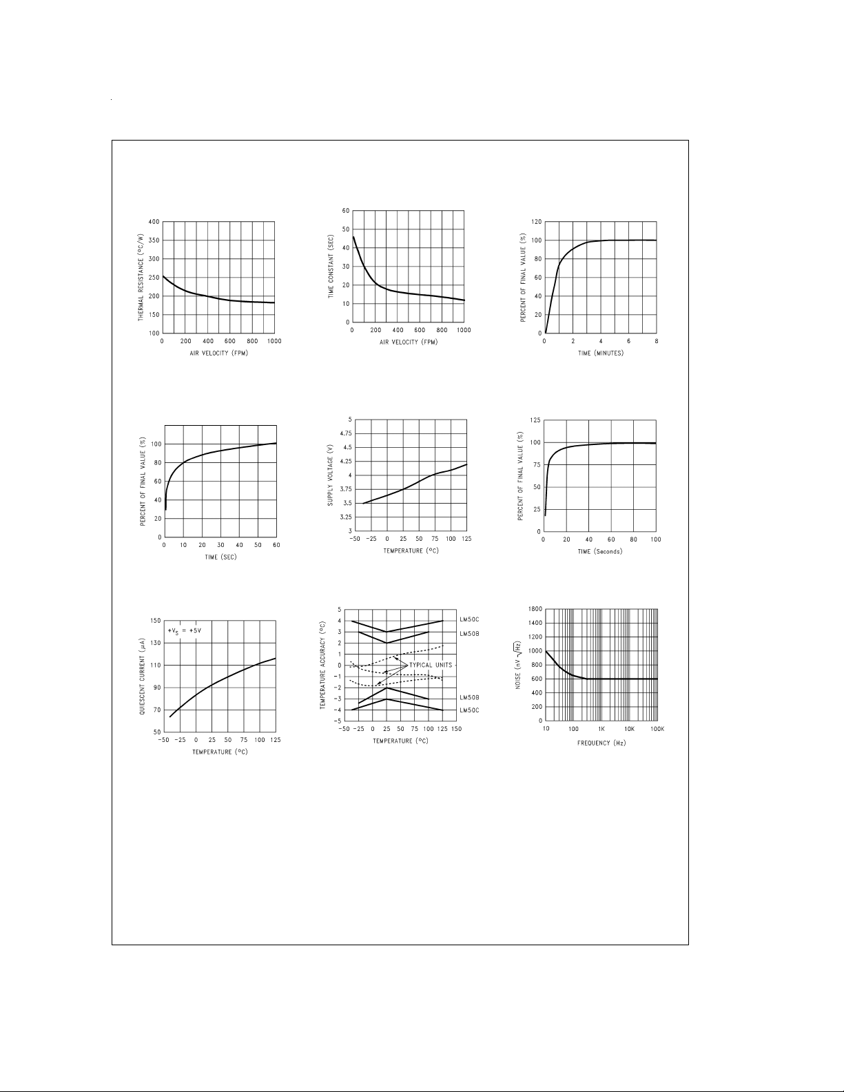
Typical Performance Characteristics To generate these curves the LM50 was mounted to a printed
circuit board as shown in
Figure 2
.
Thermal Resistance
Junction to Air
Thermal Response
in Stirred Oil Bath
with Heat Sink
Quiescent Current vs
Temperature (
Figure 1
)
DS012030-21
DS012030-24
Thermal Time Constant
Start-Up Voltage
vs Temperature
Accuracy vs Temperature
DS012030-22
DS012030-25
Thermal Response in Still Air
with Heat Sink (
Figure 2
)
DS012030-23
Thermal Response in Still
Air without a Heat Sink
DS012030-26
Noise Voltage
DS012030-27
DS012030-28
DS012030-29
www.national.com3
Page 4

Typical Performance Characteristics To generate these curves the LM50 was mounted to a printed
circuit board as shown in
Figure 2
. (Continued)
Supply Voltage
vs Supply Current
FIGURE 2. Printed Circuit Board Used
for Heat Sink to Generate All Curves.
1
⁄2" Square Printed Circuit Board
with 2 oz. Foil or Similar
DS012030-30
DS012030-19
Start-Up Response
DS012030-31
as Humiseal and epoxy paints or dips are often used to ensure that moisture cannot corrode the LM50 or its connections.
Temperature Rise of LM50 Due to Self-Heating
(Thermal Resistance, θ
)
JA
SOT-23 SOT-23
no heat sink
*
small heat fin
Still air 450˚C/W 260˚C/W
Moving air 180˚C/W
*
Part soldered to 30 gauge wire.
**
Heat sink used is1⁄2" square printed circuitboardwith 2 oz. foil withpart at-
tached as shown in
Figure 2
.
2.0 Capacitive Loads
**
1.0 Mounting
The LM50 can be applied easily in the same way as other
integrated-circuit temperaturesensors. Itcan beglued orcemented to a surface and its temperature will be within about
0.2˚C of the surface temperature.
This presumes that the ambientair temperatureis almostthe
same as the surface temperature; if the air temperature were
much higher or lower than the surface temperature, the actual temperature of the LM50die wouldbe at an intermediate
temperature between the surface temperature and the air
temperature.
To ensure good thermal conductivity the backside of the
LM50 die is directly attached to the GND pin. The lands and
traces to the LM50 will, of course, be part of the printed circuit board, which is the object whose temperature is being
measured. These printed circuit board lands and traces will
not cause the LM50s temperature to deviate from the desired temperature.
Alternatively, the LM50 can bemounted inside a sealed-end
metal tube, and can then be dipped into a bath or screwed
into a threaded hole in a tank. As with any IC, the LM50 and
accompanying wiring and circuits mustbe keptinsulated and
dry, to avoid leakage and corrosion.This is especially true if
the circuit may operate at cold temperatures where condensation can occur.Printed-circuit coatingsand varnishes such
www.national.com 4
DS012030-7
FIGURE 3. LM50 No Decoupling Required
for Capacitive Load
DS012030-8
FIGURE 4. LM50C with Filter for Noisy Environment
The LM50 handles capacitive loading very well. Without any
special precautions,the LM50 can drive anycapacitive load.
The LM50 has a nominal 2 kΩ output impedance (as can be
seen in the block diagram). The temperature coefficient of
the output resistors is around 1300 ppm/˚C. Taking into account this temperature coefficient and the initial tolerance of
the resistors the output impedance of the LM50 will not exceed 4 kΩ. Inan extremelynoisy environmentit maybe necessary to add some filtering to minimize noise pickup. It is
recommended that 0.1 µF be added from V
to GND to by-
IN
Page 5

2.0 Capacitive Loads (Continued)
pass the power supply voltage, as shown in
noisy environment it may be necessary to add a capacitor
from the output to ground. A 1 µF output capacitor with the
4kΩoutputimpedance will forma 40Hz lowpassfilter.Since
Figure 4
.Ina
the thermal time constant of the LM50 is much slower than
the 25 ms time constant formed by the RC, the overall response time of the LM50will notbe significantlyaffected. For
much larger capacitors this additional time lag will increase
the overall response time of the LM50.
*R2 ≈ 2k with a typical 1300 ppm/˚C drift.
3.0 Typical Applications
FIGURE 6. Centigrade Thermostat/Fan Controller
DS012030-17
FIGURE 5. Block Diagram
DS012030-11
DS012030-13
FIGURE 7. Temperature To Digital Converter (Serial Output) (+125˚C Full Scale)
www.national.com5
Page 6

3.0 Typical Applications (Continued)
FIGURE 8. Temperature To Digital Converter (Parallel TRI-STATE®Outputs for
Standard Data Bus to µP Interface) (125˚C Full Scale)
DS012030-14
FIGURE 9. LM50 With Voltage-To-Frequency Converter And Isolated Output
(−40˚C to +125˚C; 100 Hz to 1750 Hz)
www.national.com 6
DS012030-16
Page 7

Physical Dimensions inches (millimeters) unless otherwise noted
SOT-23 Molded Small Outline Transistor Package (M3)
Order Number LM50BIM3, or LM50CIM3
NS Package Number MA03B
LM50 SOT-23 Single-Supply Centigrade Temperature Sensor
LIFE SUPPORT POLICY
NATIONAL’S PRODUCTS ARE NOT AUTHORIZED FOR USE AS CRITICAL COMPONENTS IN LIFE SUPPORT
DEVICES OR SYSTEMS WITHOUT THE EXPRESS WRITTEN APPROVAL OF THE PRESIDENT AND GENERAL
COUNSEL OF NATIONAL SEMICONDUCTOR CORPORATION. As used herein:
1. Life support devices or systems are devices or
systems which, (a) are intended for surgical implant
into the body, or (b) support or sustain life, and
whose failure to perform when properly used in
accordance with instructions for use provided in the
2. A critical component is any component of a life
support device or system whose failure to perform
can be reasonably expected to cause the failure of
the life support device or system, or to affect its
safety or effectiveness.
labeling, can be reasonably expected to result in a
significant injury to the user.
National Semiconductor
Corporation
Americas
Tel: 1-800-272-9959
Fax: 1-800-737-7018
Email: support@nsc.com
www.national.com
National does not assume any responsibility for use of any circuitry described, no circuit patent licenses are implied and National reserves the right at any time without notice to change said circuitry and specifications.
National Semiconductor
Europe
Fax: +49 (0) 1 80-530 85 86
Email: europe.support@nsc.com
Deutsch Tel: +49 (0) 1 80-530 85 85
English Tel: +49 (0) 1 80-532 78 32
Français Tel: +49 (0) 1 80-532 93 58
Italiano Tel: +49 (0) 1 80-534 16 80
National Semiconductor
Asia Pacific Customer
Response Group
Tel: 65-2544466
Fax: 65-2504466
Email: sea.support@nsc.com
National Semiconductor
Japan Ltd.
Tel: 81-3-5639-7560
Fax: 81-3-5639-7507
 Loading...