

Page 1

PRELIMINARY
ISD1800 SERIES
SINGLE-CHIP, SINGLE-MESSAGE
VOICE RECORD/PLAYBACK DEVICE
6- TO 16-SECOND DURATION
Publication Release Date: June 7, 2005
- 1 - Revision 0.3
Page 2
ISD1800 SERIES
1. GENERAL DESCRIPTION
Winbond’s ISD1800 ChipCorder® provides high-quality, single chip, single-message, record/playback
solution with user-selectable durations of 6 to 16 seconds. The CMOS devices include an on-chip
oscillator (with external control), microphone preamplifier, automatic gain control, anti-aliasing filter,
multilevel storage array, smoothing filter, and speaker amplifier. A minimum record/playback
subsystem can be configured with a microphone, a speaker, several passive components, two push
buttons, and a power source. Recordings are stored in on-chip nonvolatile memory cells, providing
zero-power message storage. This unique, single-chip solution is made possible through Winbond’s
patented multilevel storage technology. Voice and audio signals are stored directly into memory in
their natural form, providing high-quality, solid-state voice reproduction.
2. FEATURES
• Easy-to-use single-chip, single-message voice record/playback solution
• High-quality, natural voice/audio reproduction
• Push-button interface
o Playback can be edge- or level-activated
• Variable record/playback duration controlled by external resistor selection, which sets sample rate.
Sample Rate
Duration
I1806 6 secs 7.5 secs 9 secs 12 secs
I1810 8 secs 10 secs 12 secs 16 secs
ROSC 80 K 100 K 120 K 160 K
• Automatic power-down mode
o Enters standby mode immediately following a record or playback cycle
o 0.5 µA standby current (typical)
• On-chip 8 speaker driver
• Zero-power message storage
o Eliminates battery backup circuits
• 100-year message retention (typical)
• 100,000 record cycles (typical)
• On-chip oscillator
• No algorithm development required
• Single +3 volt power supply
• Available in die form and 28-pin 300mil SOIC
o 28-pin 600mil PDIP available for samples only
8 KHz
6.4 KHz 5.3 KHz 4 HKz
- 2 -
Page 3
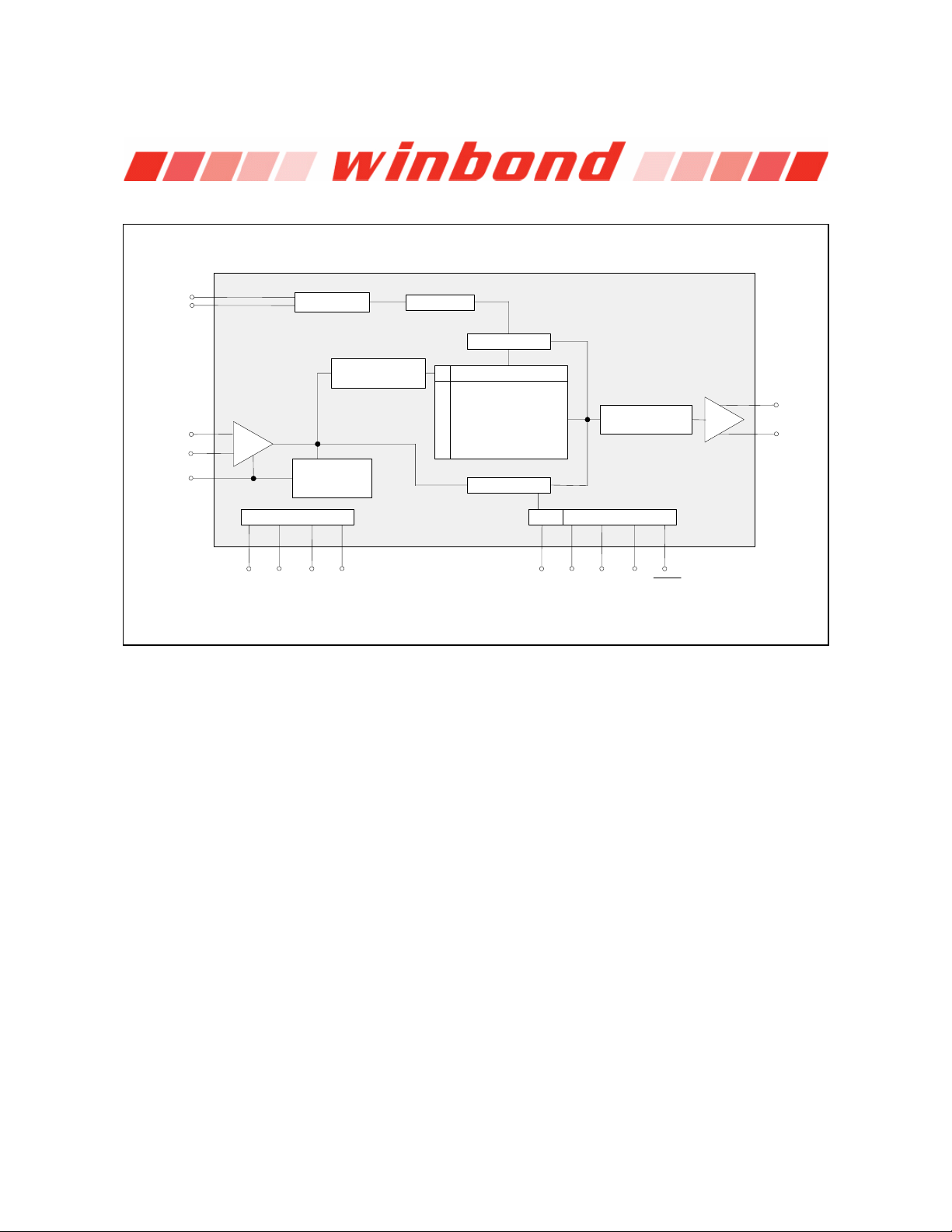
3. BLOCK DIAGRAM
ISD1800 SERIES
XCLK
ROSC
MIC
MIC REF
AGC
Internal Clock Timing
AGC
Amp
Automatic
Gain Control
(AGC)
V
CCAVSSAVSSDVCCD
Acti ve
Antialiasing Filter
Sampling Clock
Analog Transceivers
Nonvolatile
Multilevel Storage
Decoders
Arra y
Switch
Smoothing Filter
Device ControlPower Conditioning
Acti ve
SP +
Amp
SP -
RECLEDPLAYLPLAYERECFT
Publication Release Date: June 7, 2005
- 3 - Revision 0.3
Page 4

ISD1800 SERIES
4. TABLE OF CONTENTS
1. GENERAL DESCRIPTION.................................................................................................................. 2
2. FEATURES ......................................................................................................................................... 2
3. BLOCK DIAGRAM .............................................................................................................................. 3
4. TABLE OF CONTENTS ...................................................................................................................... 4
5. PIN CONFIGURATION ....................................................................................................................... 5
6. PIN DESCRIPTION............................................................................................................................. 6
7. FUNCTIONAL DESCRIPTION............................................................................................................ 9
7.1. Detailed Description.................................................................................................................. 9
7.2. Functional Description Example ........................................................................................... 10
8. TIMING DIAGRAMS.......................................................................................................................... 12
9. ABSOLUTE MAXIMUM RATINGS
9.1 Operating Conditions ............................................................................................................... 16
10. ELECTRICAL CHARACTERISTICS ............................................................................................... 17
10.1. DC Parameters...................................................................................................................... 17
10.2. AC Parameters
11. TYPICAL APPLICATION CIRCUIT................................................................................................. 19
12. PACKAGE DRAWING AND DIMENSIONS .................................................................................... 20
[1]
................................................................................................................... 18
[1]
................................................................................................ 15
12.1. 28-Lead 300mil Small Outline IC (SOIC) Package.......................................................... 20
12.2. 28-Lead 0.600-Inch Plastic Dual Inline Package (PDIP) – For Sampling Only........... 21
12.3. ISD1800 Bonding Physical Layout (Die) ........................................................................... 22
13. ORDERING INFORMATION........................................................................................................... 24
14. VERSION HISTORY ....................................................................................................................... 25
- 4 -
Page 5
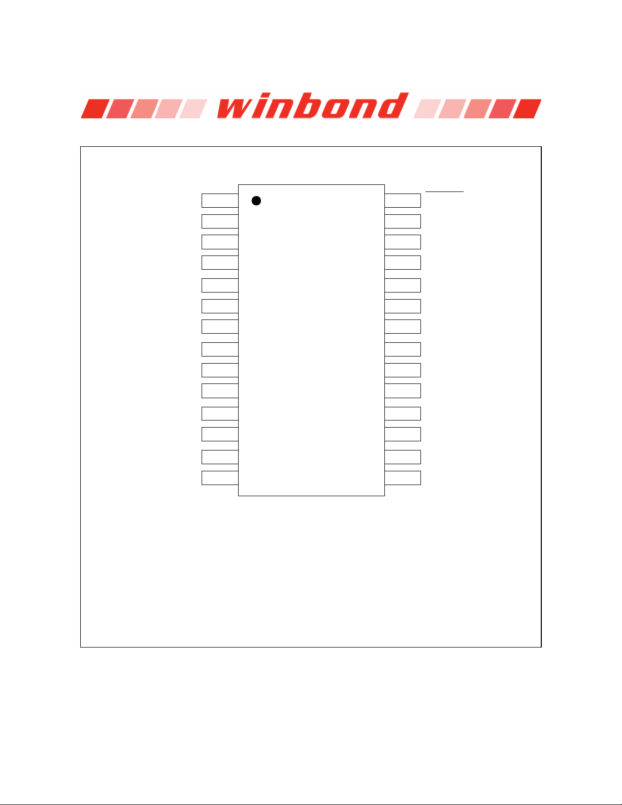
5. PIN CONFIGURATION
ISD1800 SERIES
VSSD
REC
PLAYE
PLAYL
NC
NC
NC
NC
NC
MIC
NC
MIC REF
AGC
NC
1
2
3
4
5
6
7
8
9
10
11
12
13
14
ISD1800
28
27
26
25
24
23
22
21
20
19
18
17
16
15
RECLED
VCCD
XCLK
FT
NC
NC
NC
NC
NC
ROSC
VCCA
SP+
VSSA
SP-
SOIC/PDIP
Publication Release Date: June 7, 2005
- 5 - Revision 0.3
Page 6
ISD1800 SERIES
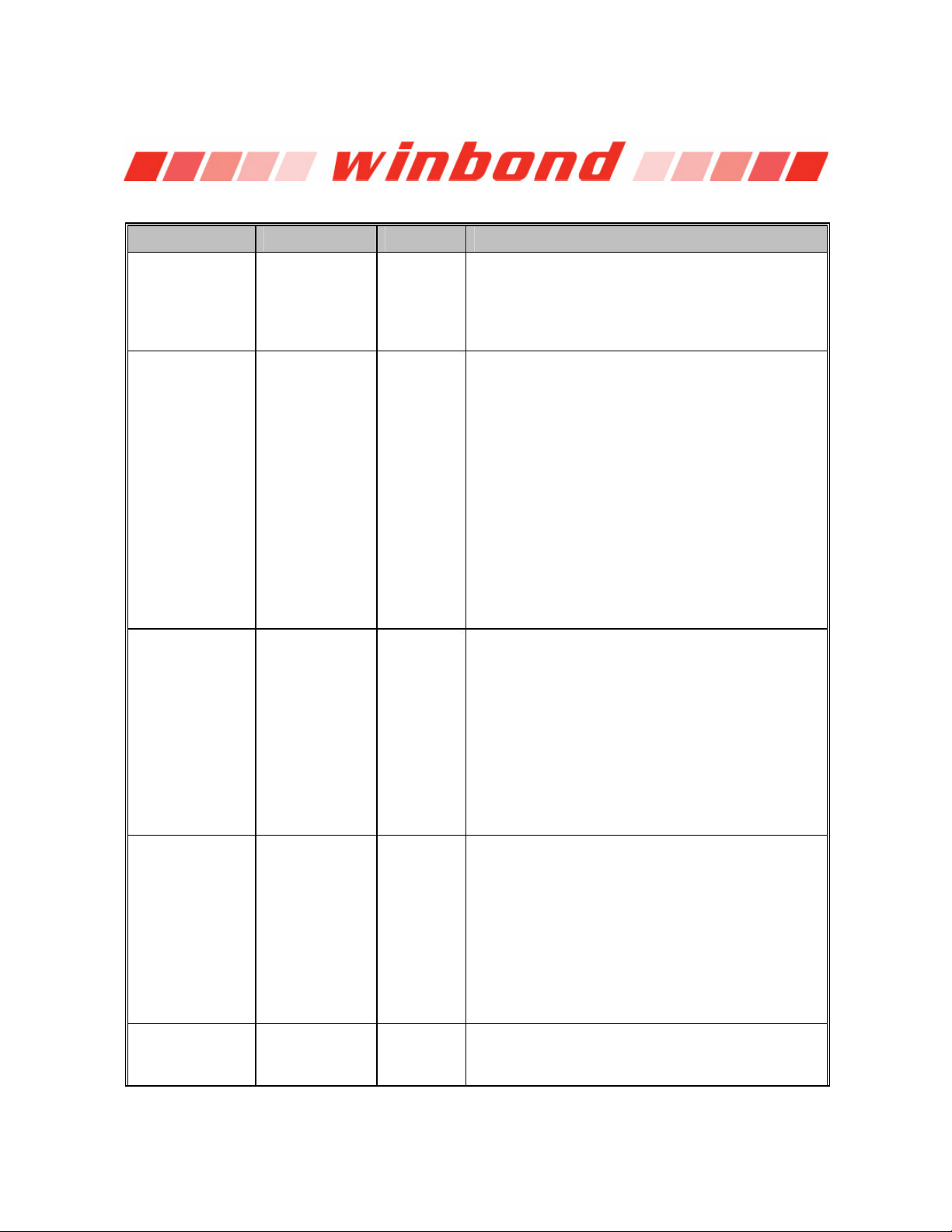
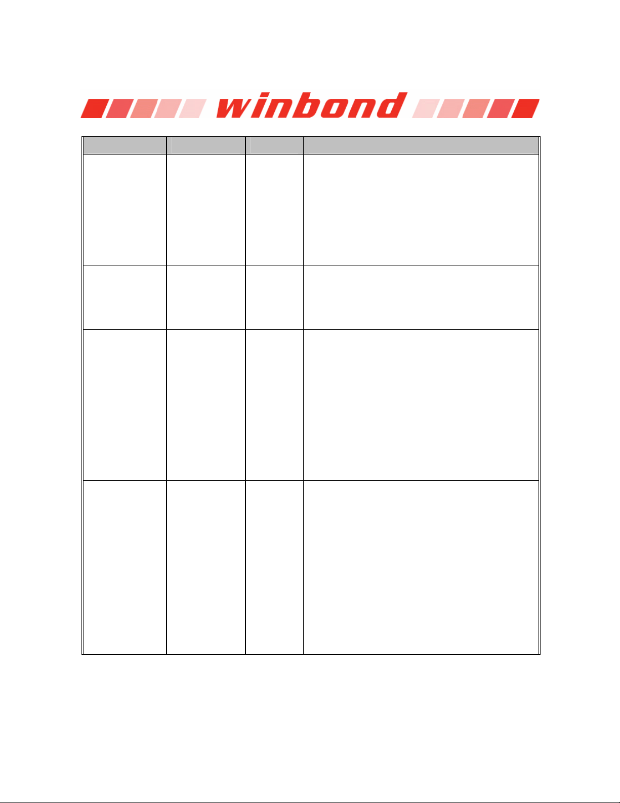
6. PIN DESCRIPTION
PIN NAME PIN NO. I/O FUNCTION
V
, V
SSD
REC
SSA
1
1, 16
2 I
Ground Supplies: Similar to V
analog and digital circuits internal to the
device use separate ground buses to minimize
noise. These pins should be tied together as
close as possible to the device.
Record: The REC input is an active-HIGH record
signal. The device records whenever REC is
HIGH. This pin must remain HIGH for the duration
of the recording. REC takes precedence over
either playback (PLAYL or PLAYE) signal. If REC
is pulled HIGH during a playback cycle, the
playback immediately ceases and recording
begins. A record cycle is completed when REC is
pulled LOW. An End-of-Message (EOM) marker
is internally recorded, enabling a subsequent
playback cycle to terminate appropriately. The
device automatically powers down to standby
mode when REC goes LOW. This pin has an
internal pull-down device. Holding this pin HIGH
will increase standby current consumption.
CCA
and V
CCD
I1800
, the
PLAYE 3 I
PLAYL 4 I
NC 5, 6, 7, 8, 9,
11, 14, 20, 21,
22, 23, 24
Not Connected.
Playback, Edge-activated: When a HIGH-going
transition is detected on this input pin, a playback
cycle begins. Playback continues until an End-ofMessage (EOM) marker is encountered or the
end of the memory space is reached. Upon
completion of the playback cycle, the device
automatically powers down into standby mode.
Taking PLAYE LOW during a playback cycle will
not terminate the current cycle. This pin has an
internal pull-down device. Holding this pin HIGH
will increase standby current consumption.
Playback, Level-activated: When this input pin
level transits from LOW to HIGH, a playback cycle
is initiated. Playback continues until PLAYL is
pulled LOW or an End-of-Message (EOM) marker
is detected, or the end of the memory space is
reached. The device automatically powers down
to standby mode upon completion of the playback
cycle. This pin has an internal pull-down device.
Holding this pin HIGH will increase standby
current consumption.
- 6 -
Page 7
ISD1800 SERIES
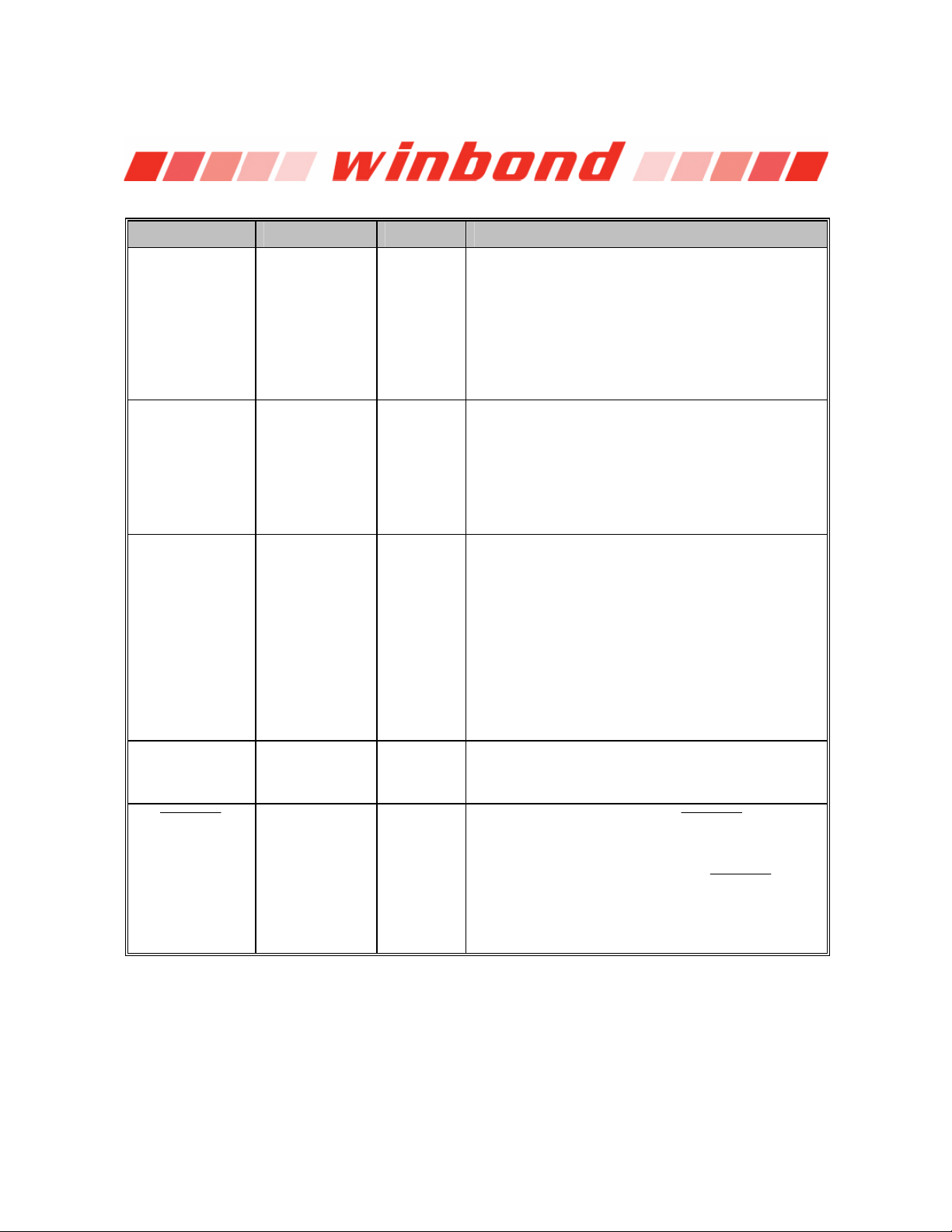
PIN NAME PIN NO. I/O FUNCTION
MIC 10 I
Microphone Input: The microphone input
transfers its signals to the on-chip preamplifier. An
on-chip Automatic Gain Control (AGC) circuit
controls the gain of the preamplifier. An external
microphone should be AC coupled to this pin via
a series capacitor. The capacitor value, together
with an internal 10 K resistance on this pin,
determines the low-frequency cutoff for the
passband.
MIC REF 12 I
Microphone Reference: The MIC REF input is
the inverting input to the microphone preamplifier.
This provides input noise-cancellation, or
common-mode rejection, when the microphone is
connected differentially to the device.
AGC 13 I
Automatic Gain Control: The AGC dynamically
adjusts the gain of the preamplifier to compensate
for the wide range of microphone input levels. The
AGC allows the full range of sound, from whispers
to loud sounds, to be recorded with minimal
distortion. Nominal values of 4.7 µF give
satisfactory results in most cases.
Connecting this pin to ground (V
maximum gain to the preamplifier circuitry.
Conversely, connecting this pin to the power
supply (V
preamplifier circuitry.
) provides
SSA
) provides minimum gain to the
CCA
I1800
SP-/SP+ 15, 17 O
Speaker Outputs: The SP+ and SP- pins provide
direct drive for loudspeakers with impedances as
low as 8. A single output may be used, but, for
direct-drive loud-speakers, the two oppositepolarity outputs provide an improvement in output
power of up to four times over a single-ended
connection. Furthermore, when SP+ and SP- are
used, a speaker coupling capacitor is not
required. A single-ended connection will require
an AC-coupling capacitor between the SP pin and
the speaker.
The SP+ pin and the SP- pin are internally
connected through a 50 K resistance. When not
in playback mode, they are floating.
Publication Release Date: June 7, 2005
- 7 - Revision 0.3
Page 8
ISD1800 SERIES
PIN NAME PIN NO. I/O FUNCTION
V
CCA
, V
CCD
18, 27
Voltage Supplies: Analog and digital circuits
internal to the
I1800 device use separate power
buses to minimize noise on the chip. These power
buses are brought out to separate pins on the
package and should be tied together as close to
the power supply as possible. It is important that
the power supply be decoupled as close as
possible to the package.
ROSC 19 I
The Resistor Controlled Oscillator input: This
enables the user to vary the
and playback duration. The resistor connected
between the ROSC pin and V
the sample frequency and the filter upper pass
band for the
I1800 device. Please refer to the
table in Duration Section for duration selection.
FT 25 I
Feed Through: This mode allows use of the
speaker drivers for external signals. The signal
between the MIC and MIC_REF pins will pass
through the AGC, the filter and the speaker
drivers to the speaker outputs SP+ and SP-. The
input FT controls the feed through mode. To
operate this mode, the control pins REC, PLAYE
and PLAYL are held LOW at V
held HIGH to V
. For normal operation of record,
CC
play and power down, the FT pin is held at V
The FT pin has a weak pull-down to V
XCLK 26
The External Clock input: For the
has an internal pull-down resistor. This pin is
used for test purposes only. Do not bond this pad.
I1800 device record
(R2) determines
SS
. The pin FT is
SS
SS
.
SS
I1800 devices
.
RECLED
28 O
Record LED output: The
RECLED
output is
LOW during a record cycle. It can be used to
drive an LED to provide feedback that a record
cycle is in progress. In addition,
RECLED
pulses
LOW momentarily when and End-of-Message
(EOM) or end-of-memory marker is encountered
in a playback cycle.
Note: 1 The REC signal is internally debounced on the rising edge to prevent a false re-triggering from a pushbutton switch.
- 8 -
Page 9

ISD1800 SERIES
7. FUNCTIONAL DESCRIPTION
7.1. DETAILED DESCRIPTION
Speech/Sound Quality
Winbond’s patented ChipCorder® technology provides natural record and playback. The input voice
signals are stored directly in nonvolatile cells and are reproduced without the synthetic effect often
heard with digital solid-state speech solutions. A complete sample is stored in a single cell, minimizing
the memory necessary to store a single message.
Duration
ISD1800 devices offer single-chip solutions with 6 to 16 seconds of record/playback duration
The
capacity. Sampling rate and duration are determined by an external resistor connected to the ROSC
pin. These specifications apply with the required resistor value for playback duration.
Sample Rate
Duration
I1806 6 secs 7.5 secs 9 secs 12 secs
I1810 8 secs 10 secs 12 secs 16 secs
ROSC 80 K 100 K 120 K 160 K
Non-Volatile Storage
ISD1800 product utilizes the on-chip Flash memory providing zero-power message storage. The
The
message is retained for up to 100 years without power. In addition, the device can be re-recorded
typically over 100,000 times.
Basic Operation
ISD1800 ChipCorder® device is controlled by the REC pin, and either of two playback pins,
The
PLAYE (edge-activated playback), and PLAYL (level-activated playback). The
configured for design simplicity in a single-message application. Device operation is explained in
section 7.2, “Functional Description Example”.
Automatic Power-Down Mode
At the end of a playback or record cycle, the
standby mode, consuming typically 0.5µA, provided that Play REC, XCLK, and FT pins are LOW (see
DC parameters, section 10). During a playback cycle, the device powers down automatically at the
end of the message. During a record cycle, the device powers down immediately after REC is
released LOW.
8 KHz
6.4 KHz 5.3 KHz 4 HKz
ISD1800 parts are
ISD1800 device automatically returns to a low-power
Publication Release Date: June 7, 2005
- 9 - Revision 0.3
Page 10

ISD1800 SERIES
7.2. FUNCTIONAL DESCRIPTION EXAMPLE
The following example operating sequence demonstrates the functionality of the ISD1800 devices.
1. Record a message filling the memory
Pulling the REC pin HIGH initiates a record cycle form the beginning of the message space. The
device will automatically power down after REC is release LOW. An EOM marker is written at the end
of message. If REC is held HIGH, the recording continues until the message space has been filled.
Once the message space is filled, recording ceases.
2. Edge-activated playback
Pulling the PLAYE pin HIGH initiates a playback cycle from the beginning of the message space.
When the device reaches the EOM marker, it automatically powers down. If a recording has filled the
message space, the entire message is played. A subsequent rising edge on PLAYE initiates a new
play cycle from the beginning of the memory.
3. Level-activated playback
Pulling the PLAYL pin HIGH initiates a playback cycle from the beginning of the message space.
When the device reaches the EOM marker, it automatically powers down. If a recording has filled the
message space, the entire message is played. A subsequent rising edge on PLAYL initiates a new
play cycle from the beginning of the memory.
4. Level-activated playback (truncated)
If PLAYL is pulled LOW any time during the playback cycle, the device stops playing and enters the
power-down mode. A subsequent rising edge on PLAYL initiates a new play cycle from the beginning
of the memory.
5. Record (interrupting playback)
The REC pin takes precedence over other operations. Any HIGH-going transition on REC initiates a
new record operation from the beginning of the memory, regardless of any current operation in
progress.
6. Record a message, partially filling the memory
A record operation need not fill the entire memory. Releasing the REC pin LOW before filling the
message space causes the recording to stop and an EOM marker to be placed. The device powers
down automatically.
7. Playback a message that partially fills the memory
Pulling the PLAYE or PLAYL pin HIGH initiates a playback cycle. The playback cycle ceases when the
EOM marker is encountered and the device then powers down.
- 10 -
Page 11

ISD1800 SERIES
RECLED
8.
The
RECLED
operation
output pin provides an active-LOW signal, which can be used to drive an LED as a
“record-in-progress” indicator. It returns to a HIGH state when the REC pin is released LOW or when
the recording is completed due to the memory being filled. This pin also pulses LOW to indicate the
end of a message has been reached.
9. ROSC operation
The duration of the device can be varied by changing the value of R2 (R
). This means the ISD1800
OSC
device can actually be between 6 to 16 seconds duration. See the curve below, which charts typical
durations when the R
is varied from 80 K to 160 K.
OSC
This feature allows frequency shifting where a recorded voice or sound can be played back faster or
slower than normal for special effects. For example, use a 100 K resistor to make the recording and
then playback with either an 80 K resistor for faster “chipmunk” talk or with a 120 K resistor for a
slower, lower voice.
Another feature is a “Pause” or interrupt function that can be done by taking the R
resistor to V
OSC
CC
to
stop playback momentarily, resuming when the resistor is connected back to ground.
Chart 1: ISD Duration Versus R
at TA = 25°C and VCC = 3.0V
OSC
0
1
8
1
I
6
0
8
1
I
Typical Duration (sec)
6 8 10 12 14 16
80 100 120 140 160
Typical R
OSC
(K )
Ω
Publication Release Date: June 7, 2005
- 11 - Revision 0.3
Page 12

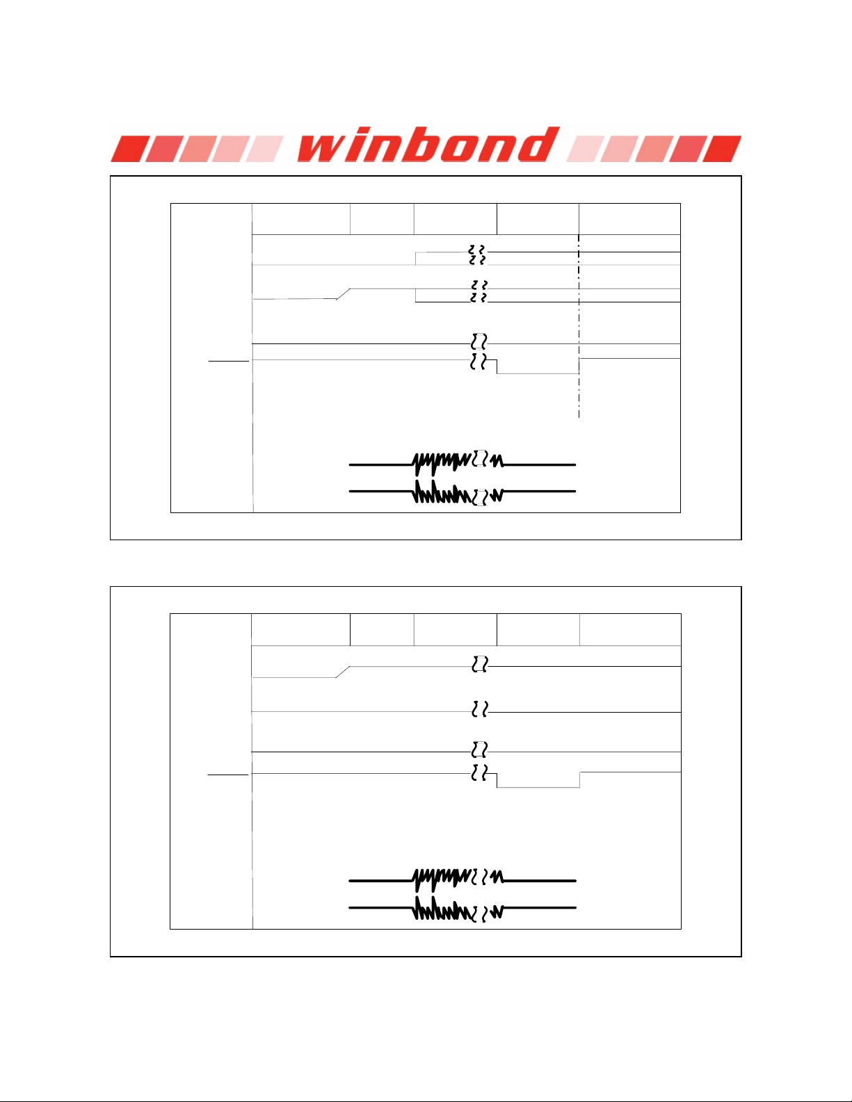
8. TIMING DIAGRAMS
ISD1800 SERIES
Power-Down
PLAYL
PLAYE
REC
RECLED
MIC
MIC REF
Debounce
84 ms
Record Power-DownOperation
INPUT MIC
INPUT MIC REF
FIGURE 1: RECORD MESSAGE UNTIL RECORD GOES LOW
Power-Down
Debounce
84 ms
Record Power-DownOperation
PLAYL
PLAYE
REC
RECLED
MIC
MIC REF
INPUT MIC
INPUT MIC REF
FIGURE 2: RECORD MESSAGE UNTIL ARRAY IS FULL
- 12 -
Page 13
ISD1800 SERIES
Debounce
84 ms
1.2 VOLTS 1.2 VOLTS
1.2 VOLTS 1.2 VOLTS
Play
Don't Care
Don't Care
Wink 84 ms Power-DownOperation
No Edges
No Edges
Open
OpenOpen
PLAYL
PLAYE
REC
RECLED
MIC
MIC REF
SP +
SP -
Power-Down
Open
FIGURE 3: PLAY EDGE (PLAYE) PLAY UNTIL END OF MESSAGE
Debounce
84 ms
1.2 VOLTS 1.2 VOLTS
1.2 VOLTS 1.2 VOLTS
Play
Wink 84 m s Power-DownOperation
Open
OpenOpen
PLAYL
PLAYE
REC
RECLED
MIC
MIC REF
SP +
SP -
Power-Down
Open
FIGURE 4: PLAY LEVEL (PLAYL) PLAY UNTIL END OF MESSAGE
Publication Release Date: June 7, 2005
- 13 - Revision 0.3
Page 14

ISD1800 SERIES
≈
≈
≈
Debounce
84 ms
1.2 VOLTS 1.2 VOLTS
1.2 VOLTS 1.2 VOLTS
Play
Wink 84 ms Power-DownOperation
Open
OpenOpen
PLAYL
PLAYE
REC
RECLED
MIC
MIC REF
SP +
SP -
Power-Down
Open
FIGURE 5: PLAY UNTIL PLAY LEVEL (PLAYL) FALLS
Operation
PLAYL
PLAYE
REC
RECLED
SP +
SP -
Power-Down
Open
Open
Debounce
84 ms
1.2 VOLTS 1.2 VOLTS
1.2 VOLTS 1.2 VOLTS
Play
Wink 84 ms Play
FIGURE 6: LOOPING PLAY, PLAYE TO
Debounce
RECLED
84 ms
- 14 -
Page 15

ISD1800 SERIES
Note: Looping playback operation can be performed by connecting the RECLED pin to PLAYE pin.
9. ABSOLUTE MAXIMUM RATINGS
ABSOLUTE MAXIMUM RATINGS (DIE)
CONDITION VALUE
Junction temperature 150°C
Storage temperature range -65°C to +150°C
Voltage applied to any pin (VSS –0.3V) to
VCC – V
Junction temperature 150°C
Storage temperature range -65°C to +150°C
Voltage applied to any pin (VSS –0.3V) to
Lead temperature (Soldering – 10sec) 300°C
VCC – V
SS
ABSOLUTE MAXIMUM RATINGS (PACKAGED PARTS)
CONDITION VALUE
SS
[1]
Stresses above those listed may cause permanent damage to the device. Exposure to the
absolute maximum ratings may affect device reliability and performance. Functional operation is
not implied at these conditions.
[1]
+0.3V)
(V
CC
-0.3V to +7.0V
+0.3V)
(V
CC
-0.3V to +7.0V
Publication Release Date: June 7, 2005
- 15 - Revision 0.3
Page 16

9.1 OPERATING CONDITIONS
Operating temperature range 0°C to +50°C
Play voltage (VCC)
Ground voltage (VSS)
Record Supply voltage (VCC)
Commercial operating temperature range (Case temperature) 0°C to +70°C
Play voltage (VCC)
Ground voltage (VSS)
Record Supply voltage (VCC)
ISD1800 SERIES
OPERATING CONDITIONS (DIE)
CONDITION VALUE
[1]
[2]
[1]
OPERATING CONDITIONS (PACKAGED PARTS)
CONDITION VALUE
[1]
[2]
[1]
+2.7V to +4.5V
0V
+2.7V to 4.5V
+2.7V to +4.5V
0V
+2.7V to 4.5V
[1]
VCC = V
[2]
VSS = V
CCA
SSA
= V
= V
CCD
SSD
- 16 -
Page 17

10. ELECTRICAL CHARACTERISTICS
10.1. DC PARAMETERS
ISD1800 SERIES
PARAMETER SYMBOL MIN
Input Low Voltage V
Input High Voltage V
Output Low Voltage V
Output High Voltage V
VCC Current (Operating) I
VCC Current (Standby) I
Input Leakage Current I
Input Current HIGH I
Input Current HIGH I
Output Load Impedance R
Preamp Input Resistance R
MIC SP+/- Gain A
IL
IH
OL
OH
CC
SB
ILPD1
ILPD2
ILPD3
EXT
MIC, RMICREF
MSP
[2]
0.8 V
2.0 V
0.4 V I
2.4 V I
30 mA V
0.5 10 µA
+1 µA Force V
30 150 400 µA Force V
3 130 µA Force V
8 Speaker Load,
10 K
40 dB AGC = 0.0V
TYP
[1]
MAX
[2]
UNITS CONDITIONS
Notes:
[1]
Typical values @ TA = 25° and VCC = 3.0V.
[2]
All Min/Max limits are guaranteed by Winbond via electrical testing or characterization. Not all
specifications are 100 percent tested.
[3]
Record LED output,
[4]
V
[5]
REC, PLAYL, PLAYE, XCLK, and FT must be at V
[6]
REC, PLAYL and PLAYE.
[7]
REC, PLAYL and PLAYE.
[8]
Test limits of Final Test.
CCA
and V
CCD
RECLED
connected together.
.
.
SSD
= 4.0 mA
OL
= -1.6 mA
OH
= 4.5V
CC
[4] [5]
SS
CC
CC
SP+ to SP-
[3]
[3]
[6]
[7]
[8]
Publication Release Date: June 7, 2005
- 17 - Revision 0.3
Page 18

10.2. AC PARAMETERS
ISD1800 SERIES
[1]
CHARACTERISTIC SYMBOL MIN
Sampling Frequency F
S
CF
ISD1806 2.2 Filter Pass Band F
ISD1810 2.2
REC
ISD1806 7.5 Record Duration T
[
3]
8 KHz
TYP
[2]
[3]
MAX
UNITS CONDITIONS
KHz
sec R
[4]
3 dB Roll-Off Point
R
= 100 K
OSC
= 100K
OSC
ISD1810 10
PLAY
ISD1806 7.5 Playback Duration T
sec R
= 100K
OSC
ISD1810 10
EOM Pulse Width T
Debounce Time T
Total Harmonic
Distortion
Speaker Output Power P
Voltage Across Speaker
EOM
DB
THD 1 %
OUT
V
OUT
84 msec
84 msec
@ 1KHz,
V
=15mV pk-to-pk
IN
24.4 mW R
1.25 2.5 Vp-p R
EXT
EXT
= 8
= 600
Pins
MIC Input Voltage 15 300 mV Peak-to-Peak
Notes:
[1]
These specifications apply with R
[2]
Typical values @ TA = 25° and VCC = 3.0V.
[3]
All Min/Max limits are guaranteed by Winbond via electrical testing or characterization. Not all
= 100K, unless stated.
OSC
specifications are 100 percent tested.
[4]
Oscillator stability may vary as much as +5% over the operating temperature and voltage ranges. (Only
the 7.5 sec duration of I1806 and 10 sec duration of I1810 are tested/guaranteed)
[5]
Low-frequency cutoff depends upon value of external capacitors (see Pin Descriptions)
[6]
Filter specification applies to the anti-aliasing filter and to the smoothing filter.
[7]
Balanced input signal applied between MIC and MIC REF as shown in the applications example. Single-
ended MIC or MIC REF recommended to be less than 100 mV peak to peak.
[5][6]
[4]
[4]
[7]
- 18 -
Page 19

11. TYPICAL APPLICATION CIRCUIT
μ
μ
μ
μ
μ
μ
ISD1800 SERIES
V
CC
DI
REC
LED
PLAYL
PLAYE
RECORD
0.001 F
C3
1 K
R6
ROSC V
R2
FT
CCD
V
CCA
V
SSD
V
SSA
SP +
SP -
C2
0.1 F
1 K
R1
Ω
(REXT)
Ω
8 '
SPEAKER
ISD1800
PLAYL
PLAYE
REC
Ω
RECLED
XCLK
MIC
MIC REF
AGC
C4
0.1 F
C6
4.7 F
R3
4.7 K
C5
0.1 F
C1
220 F
Ω
R4
4.7 K
ELECTRET
MICROPHONE
Ω
Publication Release Date: June 7, 2005
- 19 - Revision 0.3
Page 20

12. PACKAGE DRAWING AND DIMENSIONS
12.1. 28-LEAD 300MIL SMALL OUTLINE IC (SOIC) PACKAGE
ISD1800 SERIES
27
26
2
25
24
45 67
3
232221 20 19 18 171615
9101112 13
8
14
A
G
C
28
1
B
D
E
INCHES MILLIMETERS
Min Nom Max Min Nom Max
F
H
A 0.701 0.706 0.711 17.81 17.93 18.06
B 0.097 0.101 0.104 2.46 2.56 2.64
C 0.292 0.296 0.299 7.42 7.52 7.59
D 0.005 0.009 0.0115 0.127 0.22 0.29
E 0.014 0.016 0.016 0.35 0.41 0.48
F 0.050 1.27 0
G 0.400 0.406 0.410 10.16 10.31 10.41
H 0.024 0.032 0.040 0.61 0.81 1.02
Note: Lead coplanarity to be within 0.004 inches.
- 20 -
Page 21

ISD1800 SERIES
12.2. 28-LEAD 600MIL PLASTIC DUAL INLINE PACKAGE (PDIP) – SAMPLES ONLY
INCHES MILLIMETERS
Min Nom Max Min Nom Max
A 1.445 1.450 1.455 36.70 36.83 36.96
B1 0.150 3.81
B2 0.065 0.070 0.075 1.65 1.78 1.91
C1 0.600 0.625 15.24 15.88
C2 0.530 0.540 0.550 13.46 13.72 13.97
D 0.19 4.83
D1 0.015 0.38
E 0.125 0.135 3.18 3.43
F 0.015 0.018 0.022 0.38 0.46 0.56
G 0.055 0.060 0.065 1.40 1.52 1.62
H 0.100 2.54
J 0.008 0.010 0.012 0.20 0.25 0.30
S 0.070 0.075 0.080 1.78 1.91 2.03
q 0° 15° 0° 15°
Publication Release Date: June 7, 2005
- 21 - Revision 0.3
Page 22

ISD1800 SERIES
12.3. ISD1800 BONDING PHYSICAL LAYOUT (DIE)
ISD1800
PLAYL PLAYE REC V
o Die Dimensions
X: 2530µm (99.6mils)
Y: 2420µm (95.3mils)
o Die Thickness
11.5
+0.5 mil (typ)
o Pad Opening
90 x 90 microns
MIC MIC REF AGC SP - V
Notes:
1. The backside of die is internally connected to V
damage may occur.
2. Die thickness is subject to change, please contact Winbond factory for status and availability.
. It MUST NOT be connected to any other potential or
SS
RECLED
SSD
ISD1800
SSA
SP + V
V
CCD
XCLK FT
ROSC
CCA
- 22 -
Page 23

ISD1800 SERIES
ISD1800 PAD (X,Y) COORDINATES
(with respect to die center)
PAD # PAD Name Pin # X Axis (µm) Y Axis (µm)
1 AGC 13 -522.35 -1037.20
2
3 VCCD 27 122.15 1038.70
4 XCLK 26 358.38 1038.70
5 FT 25 630.45 1018.90
6 VSSD 1 -368.95 1038.70
7 REC 2 -558.98 1038.70
8 PLAYE 3 -760.15 1038.70
9 PLAYL 4 -977.35 1038.70
10 SP+ 17 465.85 -1024.10
11 ROSC 19 1007.85 -1037.20
12 VCCA 18 772.85 -1037.20
13 VSSA 16 158.85 -1037.20
14 SP- 15 -148.15 -1024.10
15 MIC 10 -977.75 -1037.20
16 MIC REF 12 -741.75 -1037.20
NC 5
NC 6
NC 7
NC 8
NC 9
NC 11
NC 14
NC 20
NC 21
NC 22
NC 23
NC 24
RECLED
28 -126.05 1038.70
Publication Release Date: June 7, 2005
- 23 - Revision 0.3
Page 24
ISD1800 SERIES
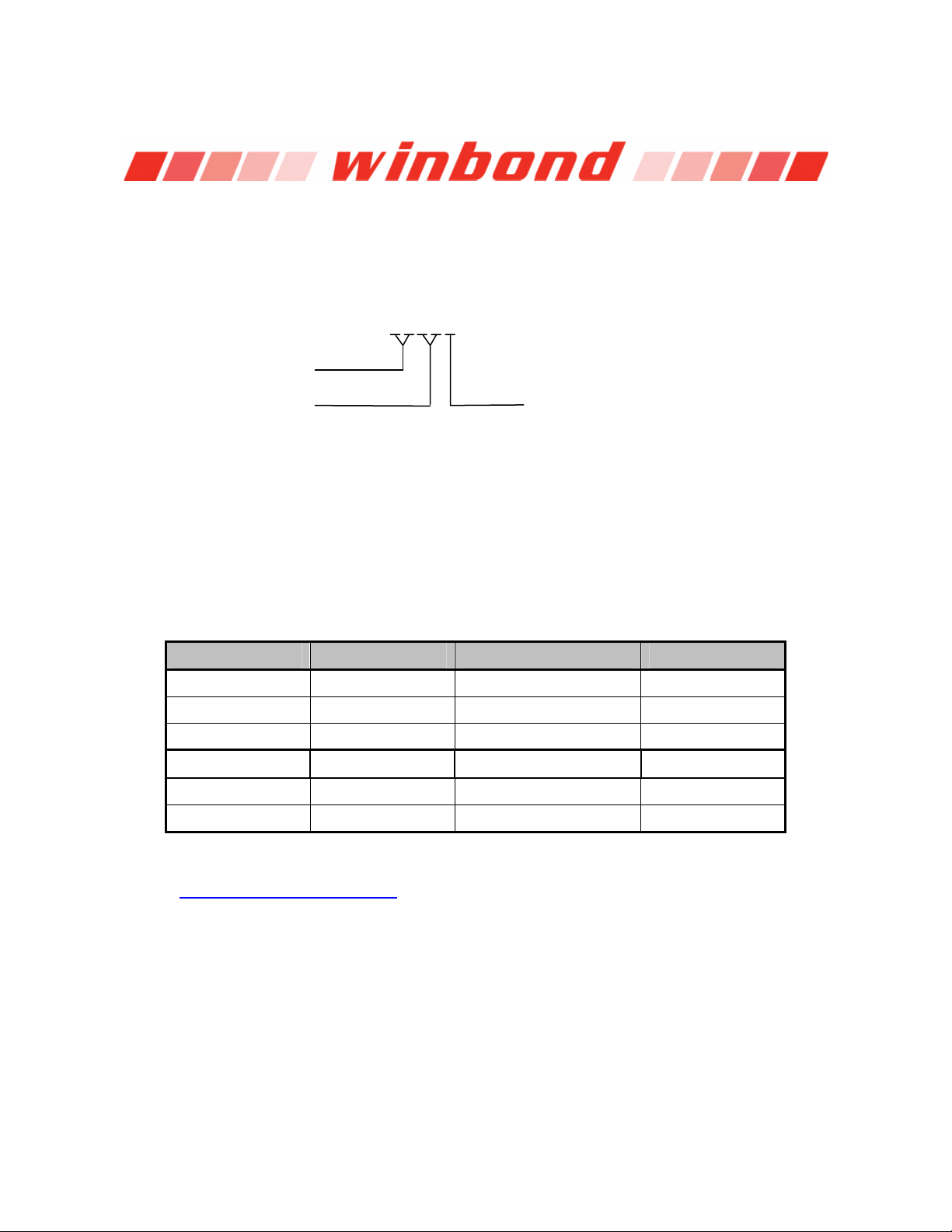
13. ORDERING INFORMATION
Product Number Descriptor Key
When ordering, please refer to the following part numbers that are supported in volume for this
product series. Consult the local Winbond Sales Representative or Distributor for availability
information.
ISD1800 Series
Duration:
06 = 6- to 12-second
10 = 8- to 16-second
ISD18xx
Package Type:
X = Die
S = Small Outline Integrated Circuit Package
(SOIC)
P = Plastic Dual Inline Package (PDIP)
Package Part Number Ordering Number Comments
Die
SOIC
PDIP
Die
SOIC
PDIP
For the latest product information, access Winbond’s worldwide website at
http://www.winbond-usa.com
ISD1806X I1806X
ISD1806S I1806S
ISD1806P I1806P Samples Only
ISD1810X I1810X
ISD1810S I1810S
ISD1810P I1810P Samples Only
- 24 -
Page 25

14. VERSION HISTORY
VERSION DATE DESCRIPTION
0.0 May 2003
0.1 Mar 2005 Revise series name from I1800 to ISD1800
0.2 Apr 2005 Revise record cycles info in feature and storage sections
0.3 Jun 2005 Revise Pout and Vout data in AC Parameters section
Preliminary Specifications. Create one datasheet for both I1806 and
I1810 products.
Revise duration section with both products.
Change filter passband values from 2.6 kHz to 2.2kHz in AC
Parameters section.
Update block diagram
Revise AGC in pin description
Revise the MIC and MIC REF polarity in applications diagram
Update die information section
Update the ordering information section
Update the disclaim section
Update the disclaim section
ISD1800 SERIES
Publication Release Date: June 7, 2005
- 25 - Revision 0.3
Page 26

ISD1800 SERIES
prop
Winbond products are not designed, intended, authorized or warranted for use as components in systems or equipment
intended for surgical implantation, atomic energy control instruments, airplane or spaceship instruments, transportation
instruments, traffic signal instruments, combustion control instruments, or for other applications intended to support or
sustain life. Furthermore, Winbond products are not intended for applications wherein failure of Winbond products could
result or lead to a situation wherein personal injury, death or severe property or environmental damage could occur.
Winbond customers using or selling these products for use in such applications do so at their own risk and agree to fully
indemnify Winbond for any damages resulting from such improper use or sales.
The contents of this document are provided only as a guide for the applications of Winbond products. Winbond makes no
representation or warranties with respect to the accuracy or completeness of the contents of this publication and
reserves the right to discontinue or make changes to specifications and product descriptions at any time without notice.
No license, whether express or implied, to any intellectual property or other right of Winbond or others is granted by this
publication. Except as set forth in Winbond's Standard Terms and Conditions of Sale, Winbond assumes no liability
whatsoever and disclaims any express or implied warranty of merchantability, fitness for a particular purpose or
infringement of any Intellectual property.
The contents of this document are provided “AS IS”, and Winbond assumes no liability whatsoever and disclaims any
express or implied warranty of merchantability, fitness for a particular purpose or infringement of any Intellectual
property. In no event, shall Winbond be liable for any damages whatsoever (including, without limitation, damages for
loss of profits, business interruption, loss of information) arising out of the use of or inability to use the contents of this
documents, even if Winbond has been advised of the possibility of such damages.
Application examples and alternative uses of any integrated circuit contained in this publication are for illustration only
and Winbond makes no representation or warranty that such applications shall be suitable for the use specified.
The 100-year retention and 100K record cycle projections are based upon accelerated reliability tests, as published in
the Winbond Reliability Report, and are neither warranted nor guaranteed by Winbond. This product incorporates
SuperFlash
Information contained in this ISD
published by ISD
This datasheet and any future addendum to this datasheet is(are) the complete and controlling ISD
product specifications. In the event any inconsistencies exist between the information in this and other product
documentation, or in the event that other product documentation contains information in addition to the information in
this, the information contained herein supersedes and governs such other information in its entirety. This datasheet is
subject to change without notice.
Copyright
Winbond Electronics Corporation. SuperFlash
are
®
.
®
®
prior to August, 1998.
©
2005, Winbond Electronics Corporation. All rights reserved. ChipCorder® and ISD® are trademarks of
erties of their respective owners.
ChipCorder® datasheet supersedes all data for the ISD ChipCorder products
®
ChipCorder®
®
is the trademark of Silicon Storage Technology, Inc. All other trademarks
- 26 -
 Loading...