

Page 1

GT864-QUAD / PY Hardware User
Guide
1vv0300756
Rev.0 - 08/05/07
Page 2

This document is relating to the following products:
GT864-QUAD/PY Hardware User Guide
1vv0300756 Rev.0 08/05/07
Model P/N
GT864-QUAD 4990150069
GT864-PY 4990150070
Reproduction forbidden without Telit Communications S.p.A. written authorization - All Rights Reserved page 2 of 23
Page 3

GT864-QUAD/PY Hardware User Guide
1vv0300756 Rev.0 08/05/07
Contents
1 Overview.............................................................................................................................................5
2 GT864 Terminal Interfaces...............................................................................................................6
3 Power Supply......................................................................................................................................7
3.1 Supply voltage requirements........................................................................................................7
3.1.1 Power Connector...................................................................................................................................................................7
3.1.2 Analogue Input GT864 PY Variant ...................................................................................................................................8
3.1.3 Digital Output........................................................................................................................................................................9
3.2 Power Consumption.....................................................................................................................9
3.3 Switching the GT864 Terminal ON and OFF.............................................................................10
4 Mini USB type connector................................................................................................................11
5 Antenna............................................................................................................................................14
5.1 General......................................................................................................................................14
5.1.1 Antenna type........................................................................................................................................................................14
5.1.2 Antenna placement..............................................................................................................................................................14
5.1.2.1 The antenna cable......................................................................................................................................................15
5.1.2.2 Antenna Connector...................................................................................................................................................15
6 Serial Ports.......................................................................................................................................16
6.1.1 RS232 standard interface connector................................................................................................................................16
7 Safety and Product Care..................................................................................................................17
7.1 General precautions...................................................................................................................17
7.2 SIM card precautions.................................................................................................................17
7.3 Antenna precautions ..................................................................................................................18
8 Installation of the modem................................................................................................................19
8.1 Where to install the modem.......................................................................................................19
8.2 How to install the modem...........................................................................................................20
8.2.1 Power supply........................................................................................................................................................................20
8.2.2 Securing the modem...........................................................................................................................................................20
9 SAFETY RECOMMANDATIONS.................................................................................................21
10 Conformity Assessment Issues........................................................................................................22
11 Document Change Log....................................................................................................................23
Reproduction forbidden without Telit Communications S.p.A. written authorization - All Rights Reserved page 3 of 23
Page 4

GT864-QUAD/PY Hardware User Guide
1vv0300756 Rev.0 08/05/07
DISCLAIMER
The information contained in this document is the proprietary information of Telit Communications
S.p.A. and its affiliates (“TELIT”). The contents are confidential and any disclosure to persons other
than the officers, employees, agents or subcontractors of the owner or licensee of this document,
without the prior written consent of Telit, is strictly prohibited.
Telit makes every effort to ensure the quality of the information it makes available. Notwithstanding the
foregoing, Telit does not make any warranty as to the information contained herein, and does not
accept any liability for any injury, loss or damage of any kind incurred by use of or reliance upon the
information.
Telit disclaims any and all responsibility for the application of the devices characterized in this
document, and notes that the application of the device must comply with the safety standards of the
applicable country, and where applicable, with the relevant wiring rules.
Telit reserves the right to make modifications, additions and deletions to this document due to
typographical errors, inaccurate information, or improvements to programs and/or equipment at any
time and without notice. Such changes will, nevertheless be incorporated into new editions of this
application note.
All rights reserved.
© 2007 Telit Communications S.p.A.
Reproduction forbidden without Telit Communications S.p.A. written authorization - All Rights Reserved page 4 of 23
Page 5
GT864
GT864
GT864
GT864
GT864
GT864
GT864
GT864-QUAD/PY Hardware User Guide
1vv0300756 Rev.0 08/05/07
1 Overview
The aim of this document is the description of some hardware solutions useful for developing a
product with the Telit GT864-QUAD/PY Terminal.
In this document all the basic functions of a mobile phone will be taken into account; for each one of
them a proper hardware solution will be suggested and eventually the wrong solutions and common
errors to be avoided will be evidenced. Obviously this document cannot embrace the whole hardware
solutions and products that may be designed. The wrong solutions to be avoided shall be considered
as mandatory, while the suggested hardware configurations shall not be considered mandatory,
instead the information given shall be used as a guide and a starting point for properly developing your
product with the Telit GT864-QUAD/PY Terminal. For further hardware details that may not be explained in
this document refer to the Telit GT864-QUAD/PY Product Description document where all the
hardware information is reported.
NOTICE
The information presented in this document is believed to be accurate and reliable. However, no responsibility is
assumed by Telit Communication S.p.A. for its use, nor any infringement of patents or other rights of third parties
which may result from its use. No license is granted by implication or otherwise under any patent rights of Telit
Communication S.p.A. other than for circuitry embodied in Telit products. This document is subject to change
without notice.
Reproduction forbidden without Telit Communications S.p.A. written authorization - All Rights Reserved page 5 of 23
Page 6
GT864-QUAD/PY Hardware User Guide
1vv0300756 Rev.0 08/05/07
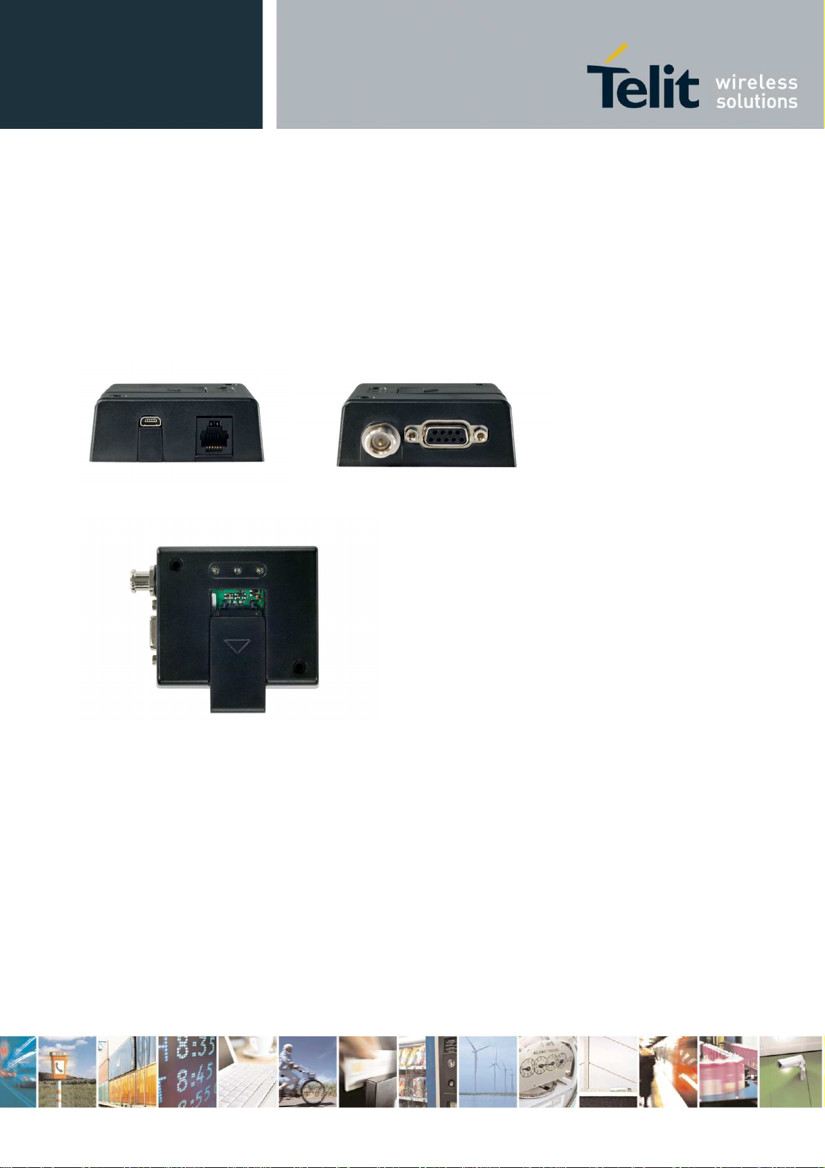
2 GT864 Terminal Interfaces
The interfaces of the GT864 Terminal are the following industry standard connectors distributed on
the front and rear panels, see figures below.
•
•
•
•
•
•
RJ11 6-way (power connector)
Analog audio (GT864-QUAD only)
4 Input (GT864-PY only)
SIM card reader
FME male coaxial jack (antenna connector)
Sub-D socket, 9 pin (RS232 serial port)
Reproduction forbidden without Telit Communications S.p.A. written authorization - All Rights Reserved page 6 of 23
Page 7
GT864-QUAD/PY Hardware User Guide
1vv0300756 Rev.0 08/05/07
3 Power Supply
3.1 Supply voltage requirements
The DC power supply must be connected to the POWER input:
• Input voltage range 5 - 36V DC
• Nominal Voltage 12V DC
Application of the supply voltage does not switch the modem on. To do so an additional active-high
control signal, TO_IN, must be applied for > 0.2s.
Please see chapter 3.3 Switching on the modem for further important details about TO_IN and power
supply requirements, especially if TO_IN is applied in parallel to VCC.
VCC and GND are reverse-polarity and over-voltage protected. Please note: this does not apply for
the GND on the antenna connector if this coax GND/shield is connected to your applications groundplane.
NOTE: In case that power supply equipment is to be ordered, its conformity needs to be verified with
the mains supply voltage, frequency, connector type and other national requirements (e.g.
certifications) in the countries of its use.
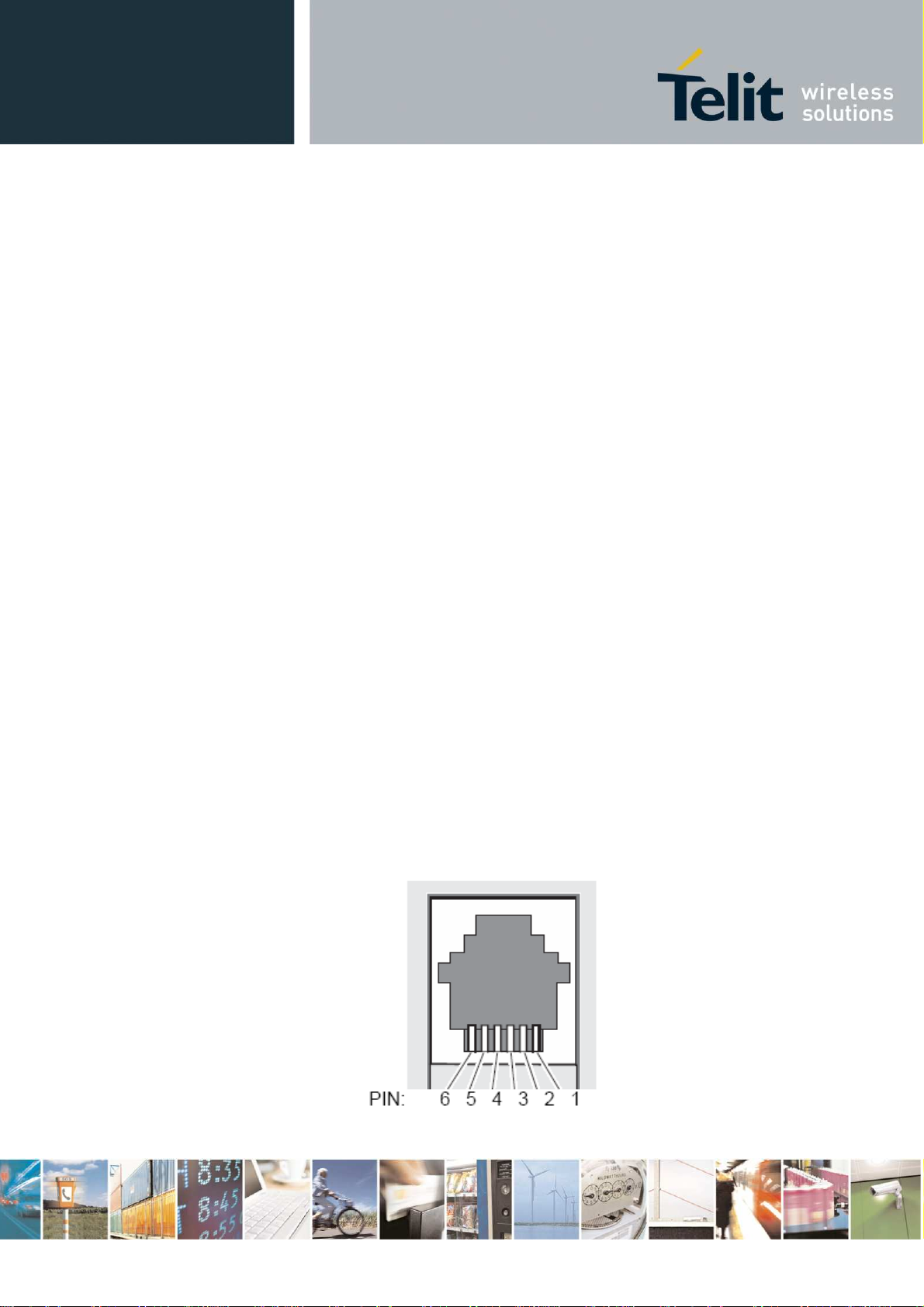
3.1.1 Power Connector
An RJ11 6-way connector, as shown and described below, serves as a means of supplying and
controlling DC power to the modem.
Reproduction forbidden without Telit Communications S.p.A. written authorization - All Rights Reserved page 7 of 23
Page 8
Pin description:
1 VCC
2 ADC_IN (not connected in GT864-QUAD Terminal)
3 HR_IN
4 TO_IN
5 DIG_OUT (not connected in GT864-QUAD Terminal)
6 GND
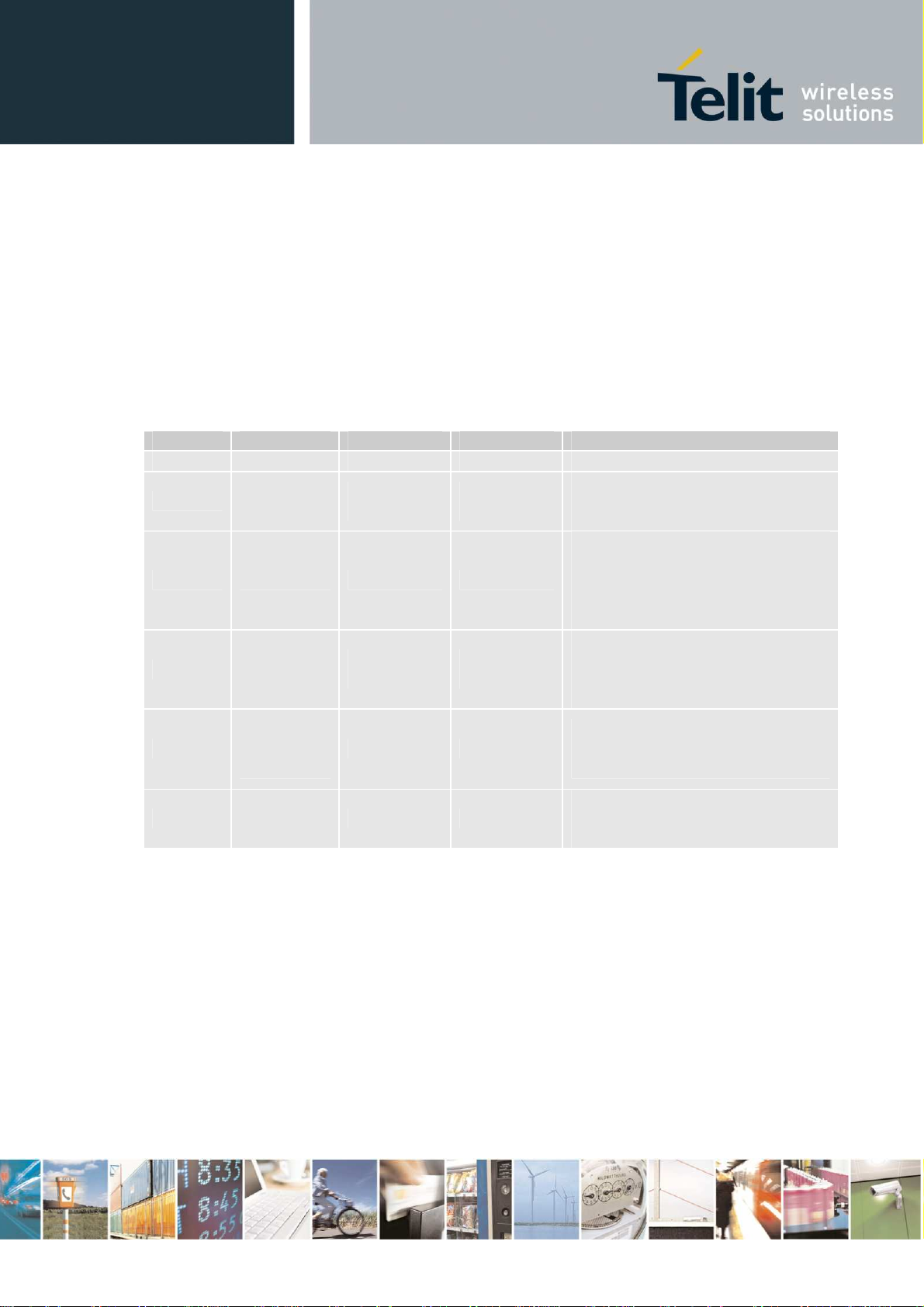
Signals of Power Connector:
PIN Signal Direction Limits Description
1 VCC Input 5 – 36V Positiv power input, DC
ADC_IN or
2
not
connected
3 HR_IN Input 5 – 36V
4
TO_IN
Input
Input
5 – 36V
5 – 36V
GT864-QUAD/PY Hardware User Guide
1vv0300756 Rev.0 08/05/07
- No connection in GT864 Quad
version
- Analogue Input in GT864 PY
Active high control line used to
switch off or reset the modem VIH
> 5V,
VIL < 0.5V Power off: 1s < t < 2s
Hard reset: t > 3.5s
Positive edge triggered signal;
used to switch on the modem VIH
> 5V, VIL < 0.5V Power on: t >
0.2s
5
DIG_OUT /
or not
connected
Output 5 – 36V
- No connection in GT864 Quad
version
- Digital Output in GT864 PY
Negative power (ground) input
6 GND Input -
and return path for TO_IN and
HR_IN
3.1.2 Analogue Input GT864 PY Variant
The following command has to be used to initialise and to read the status of the analogue input:
AT#ADC=1,2,0
Response:
#ADC: <digital value> e.g. #ADC: 119
ADC_ IN ≈ 0,026V x digital value
Reproduction forbidden without Telit Communications S.p.A. written authorization - All Rights Reserved page 8 of 23
Page 9

GT864-QUAD/PY Hardware User Guide
1vv0300756 Rev.0 08/05/07
Examples:
ADC_IN [V]
digital value
5V 12V 24V 32V
192 461 923 1230
3.1.3 Digital Output
•
switch voltage is VIN; high side switch
•
max. Output 400mA
•
short circuit protected
•
ESC protected
•
under full control of embedded application
The following command has to be used to initialise and to set the digital output:
AT#GPIO=3,1,1 switch output on
AT#GPIO=3,0,1 switch output off
3.2 Power Consumption
The measurement was realised by 4 different Voltages (5 V, 12V, 24 V and 32 V). The Terminals were
connected via RS232 cable with the PC in order to receive at commands. The temperatures were
achieved with the help of temperature chamber. The voice call with Power level 5 in GSM 900 was
established with a GSM Tester.
GT864-QUAD
Terminal switched off 0,075 0,520 1,770 2,580
On, network connection (Idle
mode)
On, network connection voice
call (power level 5) GSM 900
GT864-PY
Terminal switched off 0,008 0,557 1,768 2,596
On, network connection (Idle
mode)
On, network connection voice
call (power level 5) GSM 900
[mA] @ 5V [mA]@12V [mA] @ 24V [mA] @ 32V
52 22 16 14
203 86 41 40
[mA] @ 5V [mA]@12V [mA] @ 24V [mA] @ 32V
61 26 17 17
205 87 43 42
Reproduction forbidden without Telit Communications S.p.A. written authorization - All Rights Reserved page 9 of 23
Page 10

GT864-QUAD/PY Hardware User Guide
1vv0300756 Rev.0 08/05/07
3.3 Switching the GT864 Terminal ON and OFF
In this paragraph will be explained the way to switch the GT864 Terminals ON or OFF.
There are two ways to switch on the modem, once power is applied.
• either assert TO_IN high for > 0.2s;
• or activate the RS232 control line DTR, high for > 0.2s.
The modem is fully operational after 4 seconds. Logging onto a network may take longer than this and
is outside the control of the modem. The modem can be configured to start up at the time power is
applied by permanently tying power connector signals TO_IN (pin 4) and VCC (pin 1) together. In this
case DTR must be used to switch the modem on again after it has been switched off or reset, while
power is still applied.
NOTE: DTR must be cycled from low to high.
NOTE: The TO_IN signal requires a positive “edge” (a “sharp” signal transition from low to high) to
turn the modem on. This transition should be a rising signal from 0V (GND) to VCC, or at least a large
fraction of that voltage range, and must be applied at the same time as VCC or after it. Very slow
transitions (significantly slower than many milliseconds) or very small transitions (e.g. only a few volts
instead of 0V to VCC) will not turn on the module (since they are not considered to be a “positive
edge”).
Although this will not be an issue in almost all typical applications of the modem, under the following
condition special design care has to be taken:
• large capacitors in your power supply which will lead to slow leading and falling edges (issue
does not apply with modern stabilized switching regulator power-adaptors) AND TO_IN tied in
parallel to VCC (instead of separate dedicated digital signal)
• slow analogue signals used to assert TO_IN
• TO_IN is asserted before VCC is asserted
All 3 cases above might prevent the modem from recognizing the power-up signal this is no failure of
the modem itself, the same would apply to almost any electronic device that provides a separate
“power-on” or “reset” signal.
If you are in doubt, please
•
use the mains power adapter that is provided by your distributor and is known to work
properly with your modem
or
•
make sure that your signal and system design is according to the above
or
•
consult our support team that will be more than happy to assist you.
There are three ways to switch off (power down) the modem as described below:
• either use the AT#SHDN command;
• HR_IN t=? (defined in the paragraph 3.1.1)
• DTR permanently to GND
A delay of up to 10s is experienced as the modem logs off the network
A full system reset, independent of the status of the software, may be applied to the
modem as follows:
•
HR_IN t=? (defined in the paragraph 3.1.1)
Reproduction forbidden without Telit Communications S.p.A. written authorization - All Rights Reserved page 10 of 23
Page 11

GT864-QUAD/PY Hardware User Guide
1vv0300756 Rev.0 08/05/07
4 Mini USB type connector
There exist several different variants of the terminal module, all in (almost) the same housing, and all
equipped with the mini USB-type connector:
• Audio connector: The GT864-QUAD Terminal provides "audio signals" on that connector,
so you can connect a handset or microphone/speaker system here (available only for the GT864QUAD)
• GPIO: The programmable GT864-PY provides digital inputs on that connector, so you can
use external digital signals to control the behaviour of the terminal thereby (available only for the
GT864-PY)
By their nature these 2 different signals are completely different regarding voltage levels, signal
direction and applied energy. Especially the audio signals are quite sensitive to over-voltage, but are
only protected against it to a limited extend, since otherwise the audio signal would be significantly
detoriated. So please make sure you are using the right variant for your application and do not mix up
different variants - especially do not drive any digital signals into the USB-type-connector of the
audio-variant, since that might seriously damage the device.
The USB connector supports the connectivity of a headset or any other audio equipment using the
analogue microphone and loudspeaker interface of GT864-QUAD/PY Terminal. The table below
describes the signals on the USB connector.
Pinning Mini USB connector GT864-QUAD :
PIN Signal
1 MIC 2 EAR 3 MIC +
4 EAR +
5 not connected
Reproduction forbidden without Telit Communications S.p.A. written authorization - All Rights Reserved page 11 of 23
Page 12

GT864-QUAD/PY Hardware User Guide
1vv0300756 Rev.0 08/05/07
At the mini USB connector are 4 inputs, with the following technical description:
• max. voltage VIN is 30V
• low level: 0...1V
• high level: 4...30V
• ESD protected
• under full control of embedded application
Pinning of the USB connector for the GT864-PY:
GT864-PY GPIO
GPIO 11 D1
GPIO 12 G4
GPIO 13 K10
GPIO 14 B4
GT864-PY PIN
Mini USB
IN1
IN2
IN3
IN4
Mini USB PIN
- - GND 5
1
2
3
4
Reproduction forbidden without Telit Communications S.p.A. written authorization - All Rights Reserved page 12 of 23
Page 13

GT864-QUAD/PY Hardware User Guide
1vv0300756 Rev.0 08/05/07
All inputs are under control of an embedded application script or AT commands.
The following AT commands have to be used to initialise and to read the status of the GPIOs:
AT#GPIO=11,2,0 (read GPIO11, PIN1 Mini USB)
AT#GPIO=12,2,0 (read GPIO12, PIN2 Mini USB)
AT#GPIO=13,2,0 (read GPIO13, PIN3 Mini USB)
AT#GPIO=14,2,0 (read GPIO14, PIN4 Mini USB)
Reproduction forbidden without Telit Communications S.p.A. written authorization - All Rights Reserved page 13 of 23
Page 14

GT864-QUAD/PY Hardware User Guide
1vv0300756 Rev.0 08/05/07
5 Antenna
5.1 General
The antenna is the component in your system that maintains the radio link between the network and
the modem. Since the antenna transmits and receives electromagnetic energy, its efficient function will
depend on:
•
the type of antenna (for example, circular or directional);
•
the placement of the antenna;
•
communication disturbances in the vicinity in which the antenna operates.
In the sections below, issues concerning antenna type, antenna placement, antenna cable, and
possible communication disturbances are addressed. In any event, you should contact your local
antenna manufacturer for additional information concerning antenna type, cables, connectors, antenna
placement, and the surrounding area. You should also determine whether the antenna needs to be
grounded or not. Your local antenna manufacturer might be able to design a special antenna suitable
for your application.
5.1.1 Antenna type
Make sure that you choose the right type of antenna for the modem. Consider the following
requirements:
•
the antenna must be designed for the one of the frequency bands in use; please ask your
network provider for more information:
•
GSM 850/900 MHz
•
GSM 1800/1900 MHz;
•
the impedance of the antenna and antenna cable must be 50Ω;
•
the antenna output-power handling must be a minimum of 2W;
•
the VSWR value should be less than 3:1 to avoid any damage to the modem.
5.1.2 Antenna placement
The antenna should be placed away from electronic devices or other antennas. The recommended
minimum distance between adjacent antennas, operating in a similar radio frequency band, is at least
50cm. If signal strength is weak, it is useful to face a directional antenna at the closest radio base
station. This can increase the strength of the signal received by the modem. The modem’s peak
output power can reach 2W. RF field strength varies with antenna type and distance. At 10cm from the
antenna the field strength may be up to 70V/m and at 1m it will have reduced to 7V/m. In general, CEmarked products for residential and commercial areas, and light industry can withstand a minimum of
3V/m.
Reproduction forbidden without Telit Communications S.p.A. written authorization - All Rights Reserved page 14 of 23
Page 15

GT864-QUAD/PY Hardware User Guide
1vv0300756 Rev.0 08/05/07
5.1.2.1 The antenna cable
Use 50Ω impedance low-loss cable and high-quality 50Ω impedance connectors (frequency range up
to 2GHz) to avoid RF losses. Ensure that the antenna cable is as short as possible. The Voltage
Standing-Wave Ratio (VSWR) may depend on the effectiveness of the antenna, cable and
connectors. In addition, if you use an adapter between the antenna cable and the antenna connector,
it is crucial that the antenna cable is a high-quality, low-loss cable. Minimize the use of extension
cables, connectors and adapters. Each additional cable, connector or adapter causes a loss of signal
power.
5.1.2.2 Antenna Connector
The Telit GT864 Terminal antenna connector allows transmission of radio frequency (RF) signals
between the modem and an external customer-supplied antenna. The modem is fitted with a 50Ω FME
male coaxial jack.
Description of antenna connector parameters:
Parameter Limit Description
Nominal impedance 50Ω (SWR better than 2.5:1)
Output Power
Static Sensitivity
Watt peak (Class 4)
1 Watt peak (Class 1)
Better than –102dBm
Better than –102dBm
Extended GSM900
GSM1800
Extended GSM900
GSM1800
Reproduction forbidden without Telit Communications S.p.A. written authorization - All Rights Reserved page 15 of 23
Page 16

GT864-QUAD/PY Hardware User Guide
1vv0300756 Rev.0 08/05/07
6 Serial Ports
The RS232 standard interface serves to connect a PC, Data Terminal Equipment (DTE) or an
application, which acts as host controller of the GT864 Terminal with all its functions. Through the
RS232 interface it can be used as GSM/GPRS modem for sending and receiving of SMS, Data and
Fax calls.
The Telit GT864-PY, on the basis of the EASY SCRIPT® feature and with a PYTHON script
developed by the user, can allow self-controlled operations which put the RS232 interface in a
different serial data transmission mode, e.g. to communicate with a sensor or actuator.
6.1.1 RS232 standard interface connector
Connector type on the terminal is:
• standard RS232 Sub-D 9pin female
• Baud rate from 300 to 115.200 bit/s
• Autobauding (300 to 38.400 bit/s)
The electrical characteristics of the serial port signals are shown below:
PIN Signal Direction Voltage levels Description
1 DCD Output
2 RD Output
3 TD Input
4 DTR Input
5 GND - 0 V Ground connection
6 DSR Output
7 RTS Input
8 CTS Output
9 RI Output
To connect to a PC as DTE, a pin-to-pin, 9 pin cable with D9 type connectors on both sides is needed
(1 male & 1 female). Shielding of this cable is recommended and its length shall not exceed 3m.
> + 4V
<- 4 V
> + 4V
<- 4 V
> + 2V
< 0.8 V
> + 2V
< 0.8 V
> + 4V
<- 4 V
> + 2V
< 0.8 V
> + 4V
<- 4 V
> + 4V
<- 4 V
Data carrier detect
Received data
Transmitted data
Data terminal ready
Data set ready
Request to send
Clear to send
Ring indicator
Reproduction forbidden without Telit Communications S.p.A. written authorization - All Rights Reserved page 16 of 23
Page 17

GT864-QUAD/PY Hardware User Guide
1vv0300756 Rev.0 08/05/07
7 Safety and Product Care
Please read the information in this section and the information in “Installation
of the Modem”, before starting your integration work!
7.1 General precautions
The GT864-QUAD/PY Terminal as a stand alone item is designed for indoor use only. To use
outside it must be integrated into a weatherproof enclosure. Do not exceed the environmental and
electrical limits as specified in “Technical Data”.
•
Avoid exposing the modem to lighted cigarettes, naked flames or to extreme hot or cold
temperature.
•
Never try to dismantle the modem yourself. There are no components inside the modem that can
be serviced by the user. If you attempt to dismantle the modem, you may invalidate the warranty.
•
The GT864-QUAD/PY Terminal must not be installed or located where the surface temperature
of the plastic case may exceed 85°C.
•
All cables connected to the GT864-QUAD/PY Terminal must be secured or clamped, immediately
adjacent to the modem's connectors, to provide strain relief and to avoid transmitting excessive
vibration to the modem in the installation.
•
Ensure the d.c. cable, supplying power to the GT864-QUAD/PY Terminal, does not exceed 3
metres.
•
To protect power supply cables and meet the fire safety requirements when the unit is powered
from a battery or a high current supply, connect a fast 1.25A fuse in line with the positive supply.
•
Do not connect any incompatible component or product to the GT864-QUAD/PY Terminal.
7.2 SIM card precautions
Before handling the SIM card in your application, ensure that you are not charged with static
electricity. Use proper precautions to avoid electrostatic discharges.
•
When the SIM card hatch is opened, the SIM card connectors lie exposed under the SIM card
holder.
Caution: Do not touch these connectors! If you do, you may release an electrical discharge that could
damage the modem or the SIM card.
Reproduction forbidden without Telit Communications S.p.A. written authorization - All Rights Reserved page 17 of 23
Page 18

GT864-QUAD/PY Hardware User Guide
1vv0300756 Rev.0 08/05/07
•
When designing your application, the SIM card’s accessibility should be taken into account. We
always recommend that you have the SIM card protected by a PIN code. This will ensure that the SIM
card cannot be used by an unauthorized person.
7.3 Antenna precautions
If the antenna is to be mounted outside, consider the risk of lightning. Follow the instructions provided
by the antenna manufacturer.
•
Never connect more than one modem to a single antenna. The modem can be damaged by
radio frequency energy from the transmitter of another modem.
•
Like any mobile station, the antenna of the modem emits radio frequency energy. To avoid EMI
(electromagnetic interference), you must determine whether the application itself, or equipment in the
application’s proximity, needs further protection against radio emission and the disturbances it might
cause. Protection is secured either by shielding the surrounding electronics or by moving the antenna
away from the electronics and the external signals cable.
•
The modem and antenna may be damaged if either come into contact with ground potentials
other than the one in your application. Beware, ground potential are not always what they appear to
be.
Reproduction forbidden without Telit Communications S.p.A. written authorization - All Rights Reserved page 18 of 23
Page 19

GT864-QUAD/PY Hardware User Guide
1vv0300756 Rev.0 08/05/07
8 Installation of the modem
This chapter gives you advice and helpful hints on how to integrate the GT864-QUAD/PY Terminal
into your application from a hardware perspective. Please read the information given in “Safety and
Product Care”, chapter 7 and then read the information in this section before starting your integration
work.
8.1 Where to install the modem
There are several conditions which need to be taken into consideration when designing your
application as they might affect the modem and its function. They are:
Environmental conditions: The modem must be installed so that the environmental conditions stated
in the GT864-QUAD/PY Product Description, such as temperature, humidity and vibration are
satisfied. Additionally, the electrical specifications in the Technical Data section must not be exceeded.
GSM Signal strength: The modem has to be placed in a way that ensures sufficient GSM signal
strength. To improve signal strength, the antenna can be moved to another position. Signal strength
may depend on how close the modem is to a radio base station. You must ensure that the location at
which you intend to use the modem, is within the network coverage area. Degradation in signal
strength can be the result of a disturbance from another source, for example an electronic device in
the immediate vicinity. When an application is completed, you can verify signal strength by issuing the
AT command AT+CSQ. See “AT+CSQ Signal Strength”.
Tip: Before installing the modem, use an ordinary mobile telephone to check a possible location for it.
In determining the location for the modem and antenna, you should consider signal strength as well as
cable length.
Connections of components to GT864-QUAD/PY Terminal: The integrator is responsible for the
final integrated system. Incorrectly designed or installed, external components may cause radiation
limits to be exceeded. For instance, improperly made connections or improperly installed antennas
can disturb the network and lead to malfunctions in the modem or equipment.
Network and Subscription: Before your application is used, you must ensure that your chosen
network provides the necessary telecommunication services. Contact your service provider to obtain
the necessary information.
•
If you intend to use SMS in the application, ensure this is included in your (voice)
subscription.
•
Consider the choice of the supplementary services
Reproduction forbidden without Telit Communications S.p.A. written authorization - All Rights Reserved page 19 of 23
Page 20

GT864-QUAD/PY Hardware User Guide
1vv0300756 Rev.0 08/05/07
8.2 How to install the modem
8.2.1 Power supply
•
Use a high-quality power supply cable with low resistance. This ensures that the voltages at the
connector pins are within the allowed range, even during the maximum peak current.
•
When the unit is powered from a battery or a high current supply, connect a fast 1.25A fuse in line
with the positive supply. This protects the power cabling and modem.
8.2.2 Securing the modem
Before securing the modem take into account the amount of additional space required for the mating
connectors and cables that will be used in the application.
•
Where access is restricted, it may be easier to connect all the cables to the modem prior to
securing it in the application.
•
Securely attach the GT864-QUAD/PY Terminal modem to the host application using two 3mm
diameter pan-head screws
Reproduction forbidden without Telit Communications S.p.A. written authorization - All Rights Reserved page 20 of 23
Page 21

GT864-QUAD/PY Hardware User Guide
1vv0300756 Rev.0 08/05/07
9 SAFETY RECOMMANDATIONS
READ CAREFULLY
Be sure the use of this product is allowed in the country and in the environment required. The use of
this product may be dangerous and has to be avoided in the following areas:
Where it can interfere with other electronic devices in environments such as hospitals, airports,
aircrafts, etc
Where there is risk of explosion such as gasoline stations, oil refineries, etc
It is responsibility of the user to enforce the country regulation and the specific environment regulation.
Do not disassemble the product; any mark of tampering will compromise the warranty validity.
We recommend following the instructions of the hardware user guides for a correct wiring of the
product. The product has to be supplied with a stabilized voltage source and the wiring has to be
conforming to the security and fire prevention regulations.
The product has to be handled with care, avoiding any contact with the pins because electrostatic
discharges may damage the product itself. Same cautions have to be taken for the SIM, checking
carefully the instruction for its use. Do not insert or remove the SIM when the product is in power
saving mode.
The system integrator is responsible of the functioning of the final product; therefore, care has to be
taken to the external components of the module, as well as of any project or installation issue,
because the risk of disturbing the GSM network or external devices or having impact on the security.
Should there be any doubt, please refer to the technical documentation and the regulations in force.
Every module has to be equipped with a proper antenna with specific characteristics. The antenna has
to be installed with care in order to avoid any interference with other electronic devices and has to
guarantee a minimum distance from the body (20 cm). In case of this requirement cannot be satisfied,
the system integrator has to assess the final product against the SAR regulation.
The European Community provides some Directives for the electronic equipments introduced on the
market. All the relevant information’s are available on the European Community website:
http://europa.eu.int/comm/enterprise/rtte/dir99-5.htm
The text of the Directive 99/05 regarding telecommunication equipments is available, while the
applicable Directives (Low Voltage and EMC) are available at:
http://europa.eu.int/comm/enterprise/electr_equipment/index_en.htm
Reproduction forbidden without Telit Communications S.p.A. written authorization - All Rights Reserved page 21 of 23
Page 22

GT864-QUAD/PY Hardware User Guide
1vv0300756 Rev.0 08/05/07
10 Conformity Assessment Issues
The GT864-QUAD/PY Terminal is assessed to be conform to the R&TTE Directive as stand-alone
products, so If the module is installed in conformance with Dai Telecom installation instructions require
no further evaluation under Article 3.2 of the R&TTE Directive and do not require further involvement
of a R&TTE Directive Notified Body for the final product.
In all other cases, or if the manufacturer of the final product is in doubt then the equipment integrating
the radio module must be assessed against Article 3.2 of the R&TTE Directive.
In all cases assessment of the final product must be made against the Essential requirements of the
R&TTE Directive Articles 3.1(a) and (b), safety and EMC respectively, and any relevant Article 3.3
requirements.
The GT864-QUAD/PY Terminal is conform with the following European Union Directives:
• R&TTE Directive 1999/5/EC (Radio Equipment & Telecommunications Terminal Equipments)
• Low Voltage Directive 73/23/EEC and product safety
• Directive 89/336/EEC for conformity for EMC
In order to satisfy the essential requisite of the R&TTE 99/5/EC directive, the GT864-QUAD/PY
Terminal is compliant with the following standards:
• GSM (Radio Spectrum). Standard: EN 301 511 and 3GPP 51.010-1
• EMC (Electromagnetic Compatibility). Standards: EN 301 489-1 and EN 301 489-7
• LVD (Low Voltage Directive) Standards: EN 60 950
In this document and the Hardware User Guide, Software User Guide all the information you may
need for developing a product meeting the R&TTE Directive is included.
Reproduction forbidden without Telit Communications S.p.A. written authorization - All Rights Reserved page 22 of 23
Page 23

GT864-QUAD/PY Hardware User Guide
11 Document Change Log
Revision Date Changes
ISSUE #0 08/05/07 Initial release
1vv0300756 Rev.0 08/05/07
Reproduction forbidden without Telit Communications S.p.A. written authorization - All Rights Reserved page 23 of 23
 Loading...