

Page 1
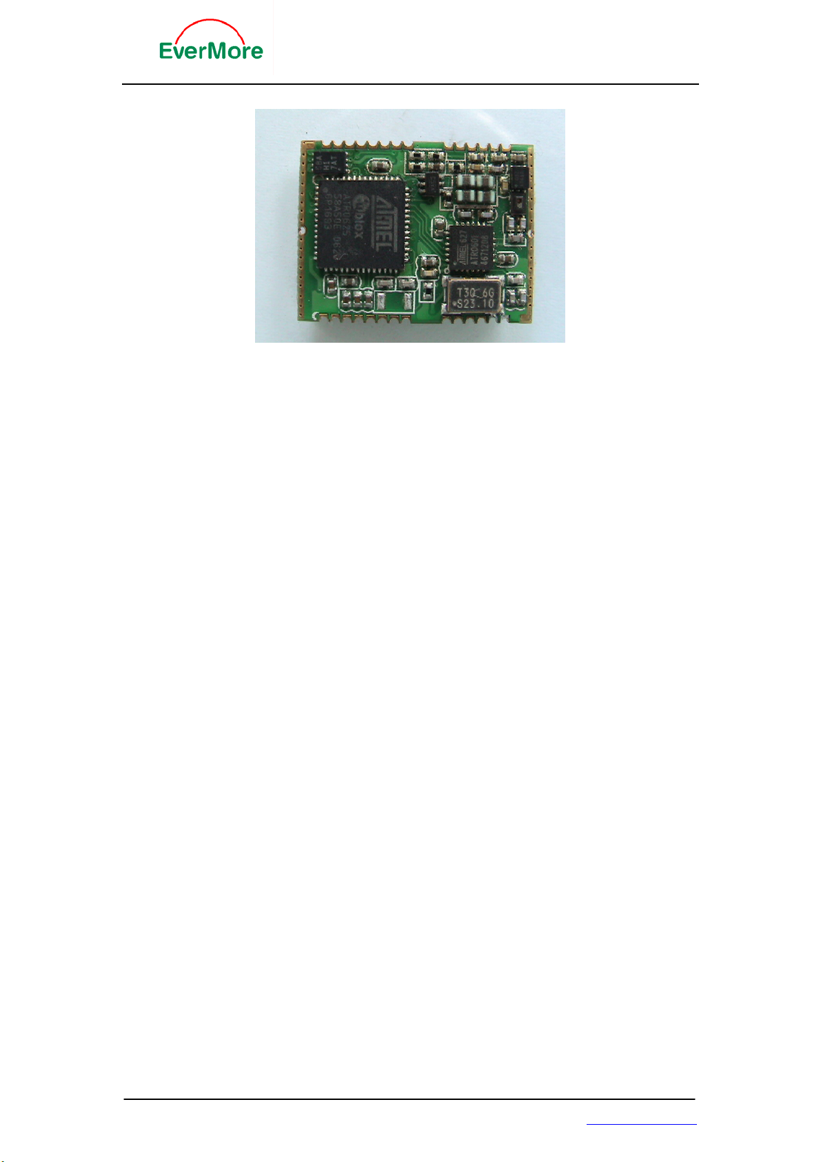
EB-A802-P GPS Engine Board
EverMore EB-A802-P is a high sensitivity, low power, SMD type GPS Module,
This product is based on Atmel chipset in 16 channel GPS receiver’s solution.
The GPS module receiver will track up to 16 satellites at a time while providing
fast time-to-first-fix and 1Hz navigation updates. It is far reaching capability
meets the sensitivity & accuracy requirements of car navigation as well as other
location-based applications, such as Personal Tracking system. PND, Handheld
Device system.
Features:
z Pin to Pin compatible ublox LEA-4P
z Atmel Chipset 16 Channels all in view tracking
z Ultra Low Power Consumption 39 mA
z High Sensitivity -158dBm
z DGPS : WAAS /EGNOS/MSAS
z Support NMEA-0183 at 4800/9600 bps baud rate
z Customized and configurable serial I/O architecture
z Support 4 Hz position update rate capability
(using on-board EEPROM)
z Support power saving modes
z Support 1 PPS
z Support 1 USB & 1 UART Port
z Lead Free , RoHS Compliant
EverMore Technology, Inc.
2F, No.7, R&D Road 1, Science-Based Industrial Park, Hsinchu, Taiwan, 300, R.O.C. http://www.emt.com.tw
Page 2

EB-A802-P GPS Engine Board
Applications:
z Land/Marine Navigation
z Telematics
z Fleet Management
z Asset Tracking
z Timing Reference
Specification:
Features Description
General L1 1575.42MHz, C/A code, 16-channel all in view
tracking
Sensitivity -158 dBm (typical)
Update Rate 1 Hz
Accuracy Position: <15m(95%) without S/A
Velocity: 0.1 m/sec without S/A
Time: ± 100ns synchronized to GPS time
Acquisition Cold start: 34 sec average
Warm start: 33 sec average
Hot start : 3.5 sec average
Dynamics Altitude : 18,000m/ Max
Velocity: 515 m/s
Acceleration: 4g Max
Reacquisition Time 0.1 second
WAAS/EGN OS Accuracy
2 m CEP
Datum WGS-84
Protocol NMEA-0183 V2.2 Baud rate: 4800/9600 ,8-None-1
UBX (ublox proprietary), RTCM
NMEA Message Default : GGA, GSA, GSV, RMC,GLL,ZDA,VTG
Primary Power 3.3VDC ± 0.1Vp-p ripple
Power Consumption 39 mA
Backup Current 5 uA typical
Serial Port UART , USB
Operation Temperature -40oC to +85 oC
Storg Temperatur e -45oC to +90oC
Operating Humidity 5% to 90% non-condensing
Interface 28 pin SMD Package / LVTTL level output
Dimension 22.4x17x3.0mm
EverMore Technology, Inc.
2F, No.7, R&D Road 1, Science-Based Industrial Park, Hsinchu, Taiwan, 300, R.O.C. http://www.emt.com.tw
Page 3

EB-A802-P GPS Engine Board
Definition of Pin assignment
Pin# Name Type Description
1
2
3
4
5
6
7
8
9
10
11
12
13~15
16
GPSMODE8 I Antenna detection configuration, keep floating
GPSMODE9 I Antenna detection configuration, keep floating
TxD1 O Serial Port 1, if not used keep floating
RxD1 I Serial Port 1, if not used keep floating
VDDIO I Pad voltage supply, 3.3V typical
VCC I Supply voltage, 3.3V typical
GND I Ground
VDD18OUT O Internal 1.8V regulator output, if not used keep floating
GPSMODE10 I Antenna detection configuration, keep floating
RESET_N I Reset Pin, active low, if not used keep floating
V_BAT I 1.5V~ 3.6V Input for backup RTC&SRAM
NC Not Connected, keep floating
GND I Ground
RF_IN I GPS signal input
17
18
19
20
21
22
23
24
25
26
27
28
GND I Ground
VCC_RF O Output Voltage RF section
V_ANT I Antenna Bias voltage
AADET_N I Active Antenna Detect (see application circuit)
GPSMODE3 I Sensitivity mode configuration, keep floating
GPSMODE2 I Sensitivity mode configuration, keep floating
USB Power Mode configuration, keep floating (Default
GPSMODE7 I
is self-powered) (“0” is bus-powered)
VDD_USB I USB Supply, 3.3V typical
USB_DM I/O USB data
USB_DP I/O USB data
EXTINT0 I External Interrupt Pin
TIMEPULSE O Time pulse (1 PPS)
EverMore Technology, Inc.
2F, No.7, R&D Road 1, Science-Based Industrial Park, Hsinchu, Taiwan, 300, R.O.C. http://www.emt.com.tw
Page 4
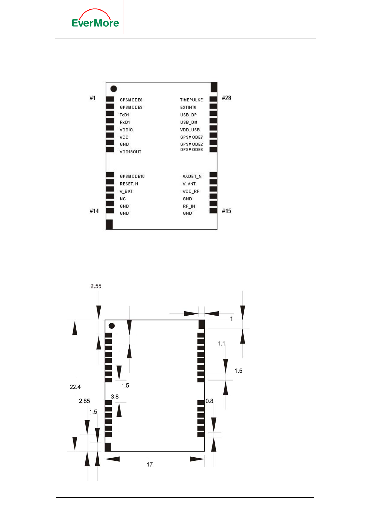
Pin Assignment
EB-A802-P GPS Engine Board
PCB TOP VIEW
Unit: mm
EverMore Technology, Inc.
2F, No.7, R&D Road 1, Science-Based Industrial Park, Hsinchu, Taiwan, 300, R.O.C. http://www.emt.com.tw
Page 5

EB-A802-P GPS Engine Board
NMEA Output Message
Table 1 NMEA-0183 Output Messages
NMEA Sentence
GGA (Default)
GLL (Default)
GSA (Default)
GSV (Default)
RMC (Default)
VTG (Default)
Description
Global positioning system fixed data
Geographic position - latitude/longitude
GNSS DOP and active satellites
GNSS satellites in view
Recommended minimum specific GNSS data
Course over ground and ground speed
GGA--- Global Positioning System Fixed Data
Table 2 contains the values for the following example:
$GPGGA,161229.487,3723.2475,N,12158.3416,W,1,07,1.0,9.0,M, , , ,0000*18
Table 2 GGA Data Format
Name Example Units Description
Message ID $GPGGA GGA protocol header
UTC Position 161229.487 hhmmss.sss
Latitude 3723.2475 ddmm.mmmm
N/S Indicator N N=north or S=south
Longitude 12158.3416 dddmm.mmmm
E/W Indicator W E=east or W=west
Position Fix
Indicator
Satellites Used 07 Range 0 to 12
HDOP 1.0 Horizontal Dilution of Precision
MSL Altitude 9.0 meters
Units M meters
Geoid Separation meters
Units M meters
Age of Diff. Corr. second Null fields when DGPS is not used
Diff. Ref. Station
ID
EverMore Technology, Inc.
2F, No.7, R&D Road 1, Science-Based Industrial Park, Hsinchu, Taiwan, 300, R.O.C. http://www.emt.com.tw
1 See Table 3
0000
Page 6
EB-A802-P GPS Engine Board
Checksum *18
<CR> <LF> End of message termination
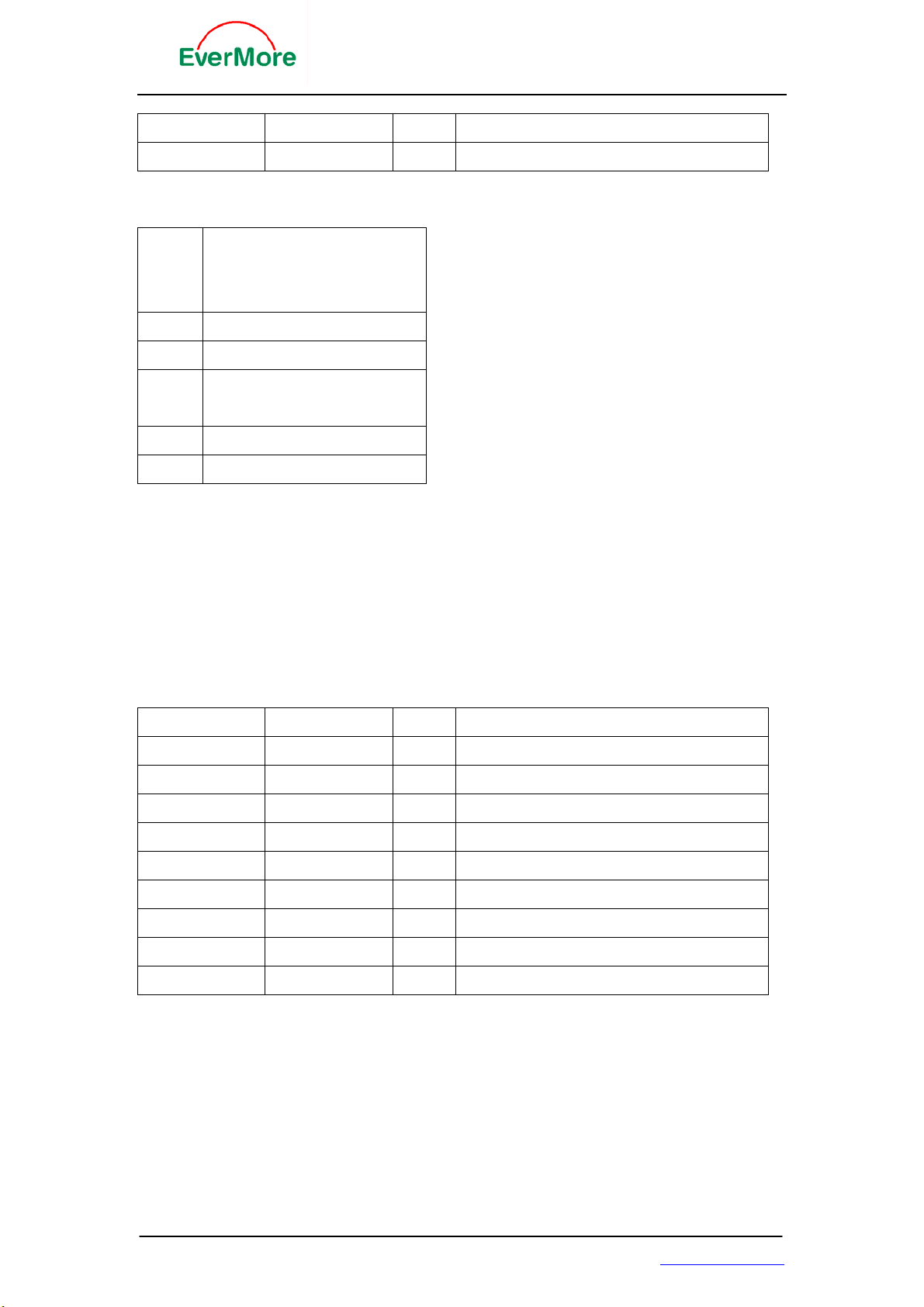
Table 3 Position Fix Indicator
Value
Description
0 Fix not available or invalid
1 GPS SPS Mode, fix valid
2 Differential GPS, SPS Mode, fix
valid
3 GPS PPS Mode, fix valid
GLL--- Geographic Position – Latitude/Longitude
Table 4 contains the values for the following example:
$GPGLL,3723.2475,N,12158.3416,W,161229.487,A*2C
Table 4 GLL Data Format
Name Example Units Description
Message ID $GPGLL GLL protocol header
Latitude 3723.2475 ddmm.mmmm
N/S Indicator N N=north or S=south
Longitude 12158.3416 dddmm.mmmm
E/W Indicator W E=east or W=west
UTC Position 161229.487 hhmmss.sss
Status A A=data valid or V=data not valid
Checksum *2C
<CR> <LF>
nd of message termination
EverMore Technology, Inc.
2F, No.7, R&D Road 1, Science-Based Industrial Park, Hsinchu, Taiwan, 300, R.O.C. http://www.emt.com.tw
Page 7
EB-A802-P GPS Engine Board
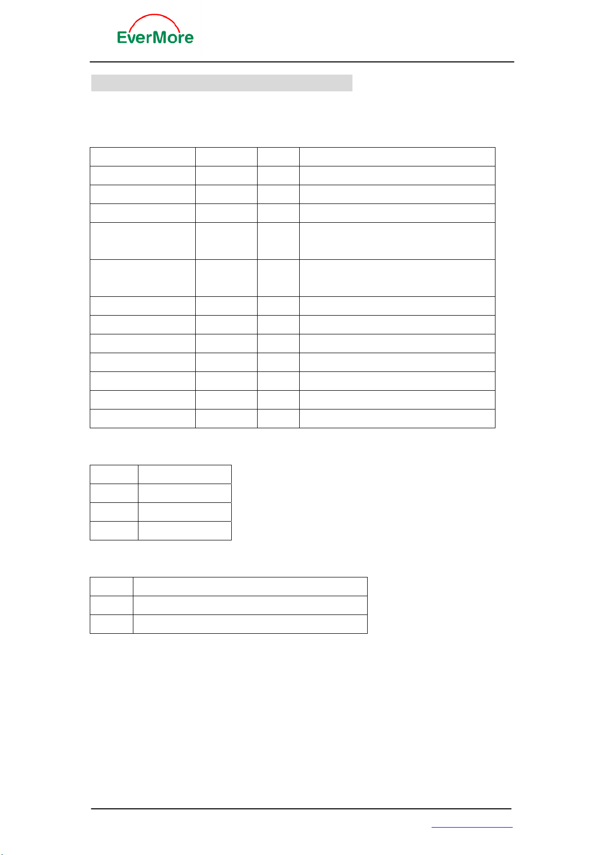
GSA---GNSS DOP and Active Satellites
Table 5 contains the values for the following example:
$GPGSA,A,3,07,02,26,27,09,04,15, , , , , ,1.8,1.0,1.5*33
Table 5 GSA Data Format
Name Example Units Description
Message ID $GPGSA
Mode 1 A See Table 7
Mode 2 3 See Table 6
Satellite Used in
solution
Satellite Used in
solution
Satellite Used Sv on Channel 12
PDOP 1.8 Position Dilution of Precision
HDOP 1.0 Horizontal Dilution of Precision
VDOP 1.5 Vertical Dilution of Precision
Checksum *33
<CR> <LF> End of message termination
Table 6 Mode 2
07 Sv on Channel 1
02 Sv on Channel 2
GSA protocol header
Value Description
1 Fix not available
2 2D
3 3D
Table 7 Mode 1
Value Description
M Manual- forced to operate i n 2D or 3D mode
A Automatic-allowed to automatically switch 2D/3D
EverMore Technology, Inc.
2F, No.7, R&D Road 1, Science-Based Industrial Park, Hsinchu, Taiwan, 300, R.O.C. http://www.emt.com.tw
Page 8

EB-A802-P GPS Engine Board
GSV---GNSS Satellites in View
Table 8 contains the values for the following example:
$GPGSV,2,1,07,07,79,048,42,02,51,062,43,26,36,256,42,27,27,138,42*71
$GPGSV,2,2,07,09,23,313,42,04,19,159,41,15,12,041,42*41
Table 8 GSV Data Format
Name Example Units Description
Message ID $GPGSV
Number of
Messages
Message Number11 Range 1 to 3
Satellites in View 07
Satellite ID 07
Elevation 79 Degrees
Azimuth 048 Degrees Channel 1 (Maximum 90)
SNR (C/No) 42 DBHz Channel 1 (True, Range 0 to 359)
Satellite ID 27 Range 0 to 99, null when not tracking
Elevation 27 Degrees Channel 4 (Range 1 to 32)
Azimuth 138 Degrees Channel 4 (Maximum 90)
SNR (C/No) 42 DBHz Channel 4 (True, Range 0 to 359)
Checksum *71 Range 0 to 99, null when not tracking
<CR> <LF> End of message termination
1. Depending on the number of satellites tracked multiple messages of GSV data may be
1
2 Range 1 to 3
GSV protocol header
Channel 1 (Range 1 to 32)
required.
RMC---Recommended Minimum Specific GNSS
Data
Table 9 contains the values for the following example:
$GPRMC,161229.487,A,3723.2475,N,12158.3416,W,0.13,309.62,120598, ,*10
Table 9 RMC Data Format
Name Example Units Description
Message ID $GPRMC
UTC Position 161229.487 hhmmss.sss
Status A A=data valid or V=data not valid
Latitude 3723.2475 ddmm.mmmm
EverMore Technology, Inc.
2F, No.7, R&D Road 1, Science-Based Industrial Park, Hsinchu, Taiwan, 300, R.O.C. http://www.emt.com.tw
RMC protocol header
Page 9

EB-A802-P GPS Engine Board
N/S Indicator N N=north or S=south
Longitude 12158.3416 dddmm.mmmm
E/W Indicator W E=east or W=west
Speed Over
Ground
Course Over
Ground
Date 120598 ddmmyy
Magnetic
Variation
Checksum *10
<CR> <LF> End of message termination
0.13 knots
309.62 degrees True
degrees E=east or W=west (Not shown)
VTG---Course Over Ground and Ground Speed
Table 10 contains the values for the following example:
$GPVTG,309.62,T, ,M,0.13,N,0.2,K*6E
Table 10 VTG Data Format
Name Example Units Description
Message ID $GPVTG VTG protocol header
Course 309.62 degrees Measured heading
Reference T True
Course degrees Measured heading
Reference M Magnetic
Speed 0.13 knots Measured horizontal speed
Units N Knots
Speed 0.2 km/hr Measured horizontal speed
Units K Kilometer per hour
Checksum *6E
<CR> <LF> End of message termination
EverMore Technology, Inc.
2F, No.7, R&D Road 1, Science-Based Industrial Park, Hsinchu, Taiwan, 300, R.O.C. http://www.emt.com.tw
 Loading...