

Page 1
General Description
The DS8102 is a stand-alone, dual-channel, deltasigma modulator that converts measurements from two
differential analog input pairs into a Manchester-encoded output bit stream that can be processed by a companion microcontroller such as the MAXQ3108. One
channel operates at a fixed 1x gain, while the other
operates at a pin-selectable gain of 1x, 4x, 16x, or 32x.
The DS8102 includes an internal power-supply monitor,
on-board voltage reference, and low-power oscillator to
reduce the number of external components required for
data acquisition.
The Manchester-encoded output from the DS8102
combines pulse-density-modulated measurement values from both differential input channels with a synchronization bit stream and is transmitted over a single
pin. This transmission scheme is ideal for split voltage
domain applications where the DS8102 and other “hot”side components must be electrically isolated from
“cold” low-voltage components such as a companion
microcontroller. In this type of application, the DS8102
can be capacitively coupled to a companion microcontroller with only two connection points required
(MNOUT and DGND).
The MAXQ3108 dual-core microcontroller, which
includes specialized Manchester bit-stream decoding
inputs and sinc3 filters, is specifically designed to act
as a companion microcontroller for up to three DS8102
devices. This configuration, which supports up to six
differential analog input channels, is well suited for
three-phase electricity-metering applications.
Applications
Single-Phase Electricity Metering
Three-Phase Electricity Metering
Power-Line Conditioning
Electrochemical and Optical Sensors
Industrial Control
Data-Acquisition Systems and Data Loggers
Features
♦ Dual Delta-Sigma 2nd-Order Modulators
Channel 0: Pin-Selectable Gain of 1x, 4x, 16x,
or 32x
Channel 1: Fixed Gain of 1x
♦ Selectable Internal or External Voltage Reference
♦ Manchester-Encoded Bit Stream Output
Includes Synchronization Bits to Allow Clock
Recovery
Single-Pin Transmission Scheme Simplifies
Electrical Isolation Using Capacitive Coupling
♦ Selectable Internal or External Clock Source
♦ Integrated Low-Power 8MHz Oscillator
♦ Operating Mode
Active Mode (8MHz, V
DD
= 3.6V): 3.5mA
DS8102
Dual Delta-Sigma Modulator and Encoder
________________________________________________________________
Maxim Integrated Products
1
Pin Configuration
Ordering Information
Rev 1; 2/09
For pricing, delivery, and ordering information, please contact Maxim Direct at 1-888-629-4642,
or visit Maxim’s website at www.maxim-ic.com.
+
Denotes a lead(Pb)-free/RoHS-compliant package.
PART TEMP RANGE PIN-PACKAGE
DS8102+ -40°C to +85°C 16 TSSOP
Typical Operating Circuit appears at end of data sheet.
MAXQ is a trademark of Maxim Integrated Products, Inc.
TOP VIEW
DGND
AGND
REF
AN1+
AN0+
DD
+
DS8102
TSSOP
161V
DD
APDREF
152
143 RSTV
134 MNOUTAN1-
CLKIO
125
G1AN0-
116
G0
107
CLKSELV
98
Page 2
DS8102
Dual Delta-Sigma Modulator and Encoder
2 _______________________________________________________________________________________
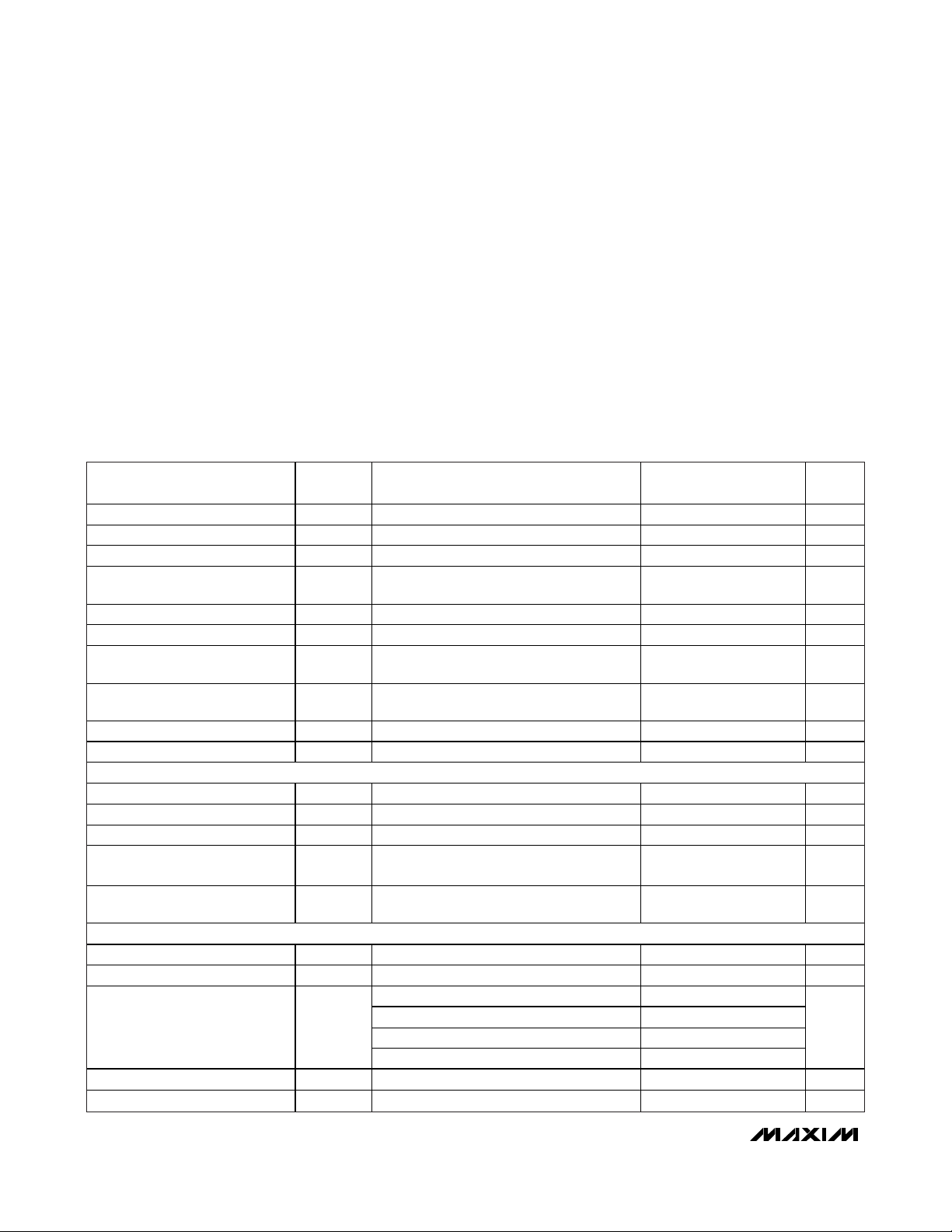
ABSOLUTE MAXIMUM RATINGS
ELECTRICAL CHARACTERISTICS
(VDD= 2.7V to 3.6V, TA= -40°C to +85°C, f
CLK
= 8MHz, V
REF
= internal, OSR = 128, unless otherwise noted.) (Note 1)
Stresses beyond those listed under “Absolute Maximum Ratings” may cause permanent damage to the device. These are stress ratings only, and functional
operation of the device at these or any other conditions beyond those indicated in the operational sections of the specifications is not implied. Exposure to
absolute maximum rating conditions for extended periods may affect device reliability.
Voltage Range on VDDRelative to DGND.............-0.3V to +4.0V
Voltage Range on V
DD
Relative to AGND.............-0.3V to +4.0V
Voltage Range on AGND Relative to DGND .........-0.3V to +0.3V
Voltage Range on Any Pin Relative to DGND
Except AN0+, AN0-, and AN1+, AN1- ...............-0.3V to +4.0V
Voltage Range on AN0+, AN0-, AN1+, and AN1-
Relative to AGND ...............................................-4.0V to +4.0V
Operating Temperature Range ...........................-40°C to +85°C
Storage Temperature Range .............................-65°C to +150°C
Soldering Temperature...........................Refer to the IPC/JEDEC
J-STD-020 Specification.
PARAMETER SYMBOL CONDITIONS MIN
Supply Voltage VDD V
Power-Fail Reset Voltage V
Active VDD Current IDD Normal operation 3.5 5.0 mA
Shutdown (Power-Down) V
Current
Input Low Voltage VIL DGND 0.3 x VDD V
Input High Voltage VIH 0.7 x VDD VDD V
Output Low Voltage
(CLKIO, MNOUT)
Output High Voltage
(CLKIO, MNOUT)
Input/Output Pin Capacitance CIO (Note 3) 15 pF
Input Leakage Current (All Inputs) IL -100 +100 nA
CLOCK SOURCE
External Cloc k Input Frequency f
External Clock Input Period t
External Cloc k Input Dut y Cycle t
Internal Oscillator Output
Frequency
Internal Oscillator Output Duty
Cycle
ANALOG-TO-DIGITAL CONVERTER
AFE Warmup Delay t
Reference Buffer Warmup Delay t
Decimator Output (Note 6)
Integral Nonlinearity INL (Notes 1, 6) ±0.01 %FSR
Offset Error Gain = 1 (Note 6) 1.4 mV
DD
XCLK-CLCL
XCLK -DUTY
t
ICLK-DUTY
Monitors VDD 2.7 2.8 2.99 V
RST
I
RST = 0 or VDD < V
STOP
V
IOL = 4mA DGND 0.4 V
OL
IOH = -4mA VDD - 0.4 V
V
OH
CLKSEL = 1 DC 8 MHz
XCLK
CLKSEL = 1 125 ns
CLKSEL = 1 40 60 %
f
CLKSEL = 0 7.5 8.0 8.5 MHz
ICLK
CLKSEL = 0 47.8 49.1 49.7 %
f
WU1
WU2
ICLK
f
ICLK
OSR = 32 16
OSR = 64 19
OSR = 128 22
OSR = 256 24
TYP
(Note 2)
3.3 3.6 V
RST
2 nA
RST
= 8MHz (Notes 1, 4) 1.02 ms
= 8MHz (Notes 1, 5) 7.17 ms
MAX UNITS
Bits
Page 3
DS8102
Dual Delta-Sigma Modulator and Encoder
_______________________________________________________________________________________ 3
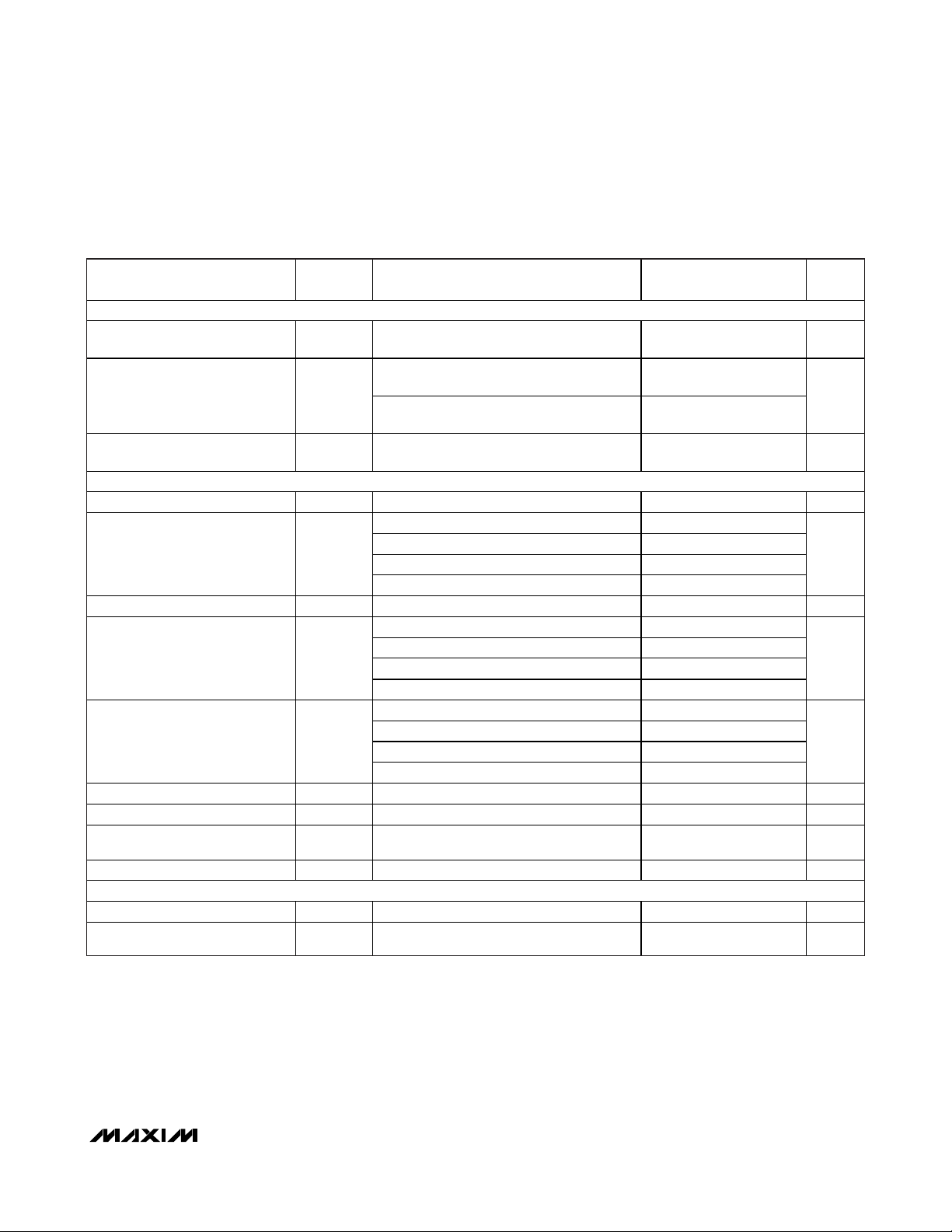
ELECTRICAL CHARACTERISTICS (continued)
(VDD= 2.7V to 3.6V, TA= -40°C to +85°C, f
CLK
= 8MHz, V
REF
= internal, OSR = 128, unless otherwise noted.) (Note 1)
Note 1: Specifications to -40°C are guaranteed by design and not production tested.
Note 2: Typical values are not guaranteed. These values are measured at room temperature, V
DD
= 3.3V.
Note 3: These numbers are guaranteed by design and are not tested.
Note 4: Calculated as t
WU1
= 1/f
ICLK
x 8192.
Note 5: Calculated as t
WU2
= 1/f
ICLK
x 57,344.
Note 6: Parameter specifications are based upon the presence of an external cubic sinc filter (as implemented in the MAXQ3108)
for generating full ADC output codewords.
Note 7: f
S
= f
CLK
/12. f
CLK
is the system clock frequency.
Note 8: This is a function of input sampling capacitance (C
IN
) and sampling frequency, and can be approximated as 6/(f
CLK
x CIN).
Note 9: Z
IN
(differential) = 2 x ZIN(single-ended).
PARAMETER SYMBOL CONDITIONS MIN
ANALOG-TO-DIGITAL CONVERTER DYNAMIC SPECIFICATIONS
DC Power-Supply Rejection Ratio PSRR
Signal-to-Noise Ratio SINAD
Total Harmonic Distortion
(to 21st Harmon ic)
ANALOG-TO-DIGITAL CONVERTER INPUTS
Input Voltage Range AN0+, AN0-, AN1+, and AN1- to AGND -1 +1 V
Input Sampling Capacitance
(Note 1)
Input Sampl ing Rate fS Cloc k at 8MHz (Note 7) 0.667 MHz
Input Impedance to AGND for
8MHz (Note 8)
Differential Input Impedance for
8MHz (Note 9)
Input Bandwidth (-3dB) 7 kHz
External Reference Input Voltage V
External Reference Input
Sampling Capacitance
Reference Input Sampling Rate fS 0.67 1 MHz
INTERNAL REFERENCE
Reference Output Voltage 1.24 V
Reference Output Temperature
Coefficient
V
DD
100mV ripple on V
VDD = 3.6V, gain = 1, AN0 = 500mV
sinewave at 62.5Hz
V
DD
sinewave at 62.5Hz
V
THD
C
IN
REF
2 pF
±30 ppm/°C
DD
sinewave at 62.5Hz
Gain = 1 1
Gain = 4 4
Gain = 16 16
Gain = 32 32
Gain = 1 750
Gain = 4 187
Gain = 16 47
Gain = 32 23.4
Gain = 1 1500
Gain = 4 375
Gain = 16 94
Gain = 32 46.9
1.2 1.25 1.3 V
= 3.0V to 3.6V, AN0+ = AN0- = AGND,
DD
,
P-P
= 3.6V, gain = 32, AN0 = 20mV
= 3.6V, gain = 32, AN0 = 20mV
P-P
P-P
,
,
95 dB
70 85
70 85
-95 -70 dB
TYP
(Note 2)
MAX UNITS
dB
pF
k
k
Page 4
DS8102
Dual Delta-Sigma Modulator and Encoder
4 _______________________________________________________________________________________
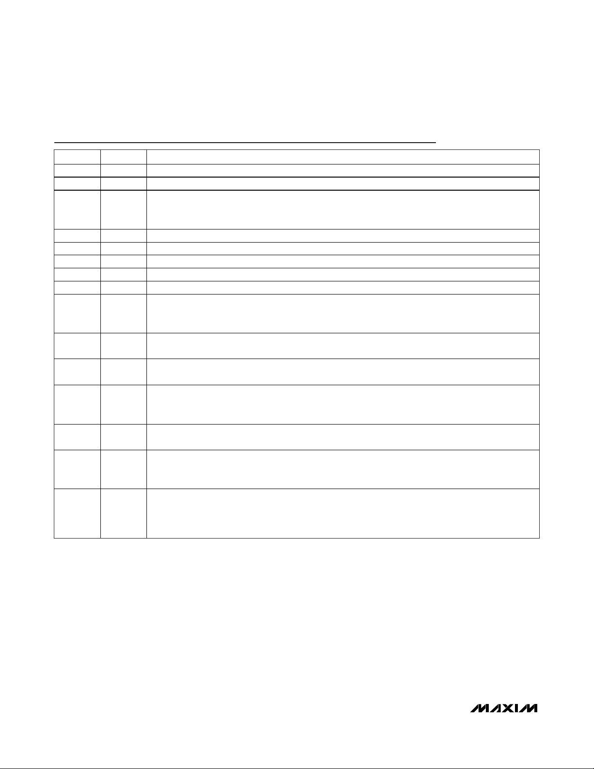
Pin Description
PIN NAME FUNCTION
1 DGND Digital Ground
2 AGND Analog Ground
Reference Voltage Input/Output. When APDREF = 0, the buffered internal voltage reference is driven on
3 V
4 AN1- Negative Input for Differential Analog Input Channel 1
5 AN1+ Positive Input for Differential Analog Input Channel 1
6 AN0- Negative Input for Differential Analog Input Channel 0
7 AN0+ Positive Input for Differential Analog Input Channel 0
8, 16 VDD Digital and Analog Power Supply
9 CLKSEL
REF
this pin as an output and can be used by other devices. When APDREF = 1, an external voltage
reference must be provided on this pin.
Clock Select Input. When CLKSEL = 0, the DS8102 uses its internal 8MHz oscillator as a clock source.
When CLKSEL = 1, the DS8102 operates from an external clock source (which must be provided at
CLKIO).
10 G0
11 G1
12 CLKIO
13 MNOUT
14 RST
15 APDREF
Gain Select Input 0. This pin, along with G1, is used to select the gain setting for differential analog
input channel 0.
Gain Select Input 1. This pin, along with G0, is used to select the gain setting for differential analog
input channel 0.
Clock Input/Output. When CLKSEL = 0 (internal clock selected), the internal 8MHz clock is output on
this pin and can be used by external devices. When CLKSEL = 1 (external clock selected), an external
clock must be provided on this pin.
Manchester Encoder Output. This output pin provides a Manchester-encoded bit stream containing
output bits from both modulators interleaved with an alternating synchroniza tion bit.
Reset. This input pin can be used to force the DS8102 into a shutdown (low-power) state by driving
RST = 0. If the external reset function is not used, this pin must be connected to V
operation. An RC circuit is not required on this pin for power-up, as this function is provided internally.
Analog Power-Down Reference. This input pin controls whether the internal voltage reference is
enabled. If APDREF = 0, the internal vo ltage reference is enabled and the voltage reference level is
driven out on V
reference must be provided on V
for proper
DD
. If APDREF = 1, the internal vo ltage reference is di sabled and an external voltage
REF
REF
.
Page 5

DS8102
Dual Delta-Sigma Modulator and Encoder
_______________________________________________________________________________________ 5
Detailed Description
Operating Modes
The DS8102 has two operating modes: shutdown (or
power-down) mode and active mode.
Shutdown Mode
In shutdown mode, the DS8102 is in an inactive state
and consumes a minimal amount of current. No analogto-digital conversion or encoding is performed, and the
internal 8MHz oscillator and internal voltage reference
are disabled.
An integrated power-supply monitor holds the DS8102
in shutdown mode whenever VDD≤ V
RST
. Additionally,
the RST pin can be driven low by an external companion microcontroller (such as the MAXQ3108) to force the
DS8102 to remain in shutdown mode, regardless of the
supply level at VDD. This is useful in nonisolated configurations (when a power supply is shared between the
DS8102 and the companion microcontroller) to reduce
the current consumption of the entire system. In this
scenario, the companion microcontroller would perform
this sequence of actions when entering stop mode:
1) Drive the RST line on the DS8102 low to force the
DS8102 into shutdown mode.
2) Enter stop mode. Both the companion microcontroller and the DS8102 are now in their lowest current consumption modes.
3) Exit stop mode.
4) Drive the RST line on the DS8102 high to return the
DS8102 to active mode.
Note: The RST line on the DS8102 does not include
a pullup. This means that if the RST line is not driven by a companion microcontroller, RST must be
connected to V
DD
for proper operation. RST cannot
be left unconnected.
While the DS8102 is in shutdown mode, the levels on
the configuration input pins (APDREF, CLKSEL, G1,
and G0) can be changed if they are being driven by a
companion microcontroller instead of hardwired to V
DD
or DGND. However, once the DS8102 enters active
mode, the levels on these pins must remain static for
proper operation.
Functional Diagram
V
REF
AN1+
AN1-
AN0+
AN0-
APDREF
INTERNAL
REFERENCE
G1
G0
REFERENCE
BUFFER
1x
INTEGRATORS/
COMPARATOR
DELTA-SIGMA MODULATOR
1x, 4x,
16x, 32x
INTEGRATORS/
COMPARATOR
DELTA-SIGMA MODULATOR
RST
8MHz
OSCILLATOR
DS8102
MANCHESTER
ENCODER
POWER
MONITOR
DGNDAGND
V
DD
CLKSEL
CLKIO
MNOUT
Page 6

DS8102
Dual Delta-Sigma Modulator and Encoder
6 _______________________________________________________________________________________
Once the power supply is at an acceptable level
(VDD>V
RST
) and the RST line is driven high, the
DS8102 exits shutdown mode. However, a warmup
sequence must then be completed before analog-todigital conversion and Manchester encoding begins.
The length of this sequence depends on the
internal/external voltage reference mode (controlled by
the APDREF pin).
If the external voltage reference is selected (APDREF = 1),
the following actions are performed:
1) Upon exit from shutdown mode (VDD> V
RST
and
RST = 1), the 8MHz oscillator is started.
2) The DS8102 delays for 16 cycles of the 8MHz oscil-
lator. This allows the 8MHz oscillator to warm up.
3) The analog front-end (AFE) is enabled.
4) The DS8102 delays for 8192 cycles of the 8MHz
oscillator. This allows the AFE to warm up.
5) If CLKSEL = 1, the 8MHz oscillator is disabled at
this point and the DS8102 switches to the external
clock source provided at CLKIO.
6) Both modulator channels are enabled, and the
DS8102 begins performing conversions using the
external voltage reference.
If the internal voltage reference is selected (APDREF = 0),
the followings actions are performed:
1) Upon exit from shutdown mode (VDD> V
RST
and
RST = 1), the 8MHz oscillator is started.
2) The DS8102 delays for 16 cycles of the 8MHz oscil-
lator. This allows the 8MHz oscillator to warm up.
3) The AFE is enabled.
4) The DS8102 delays for 8192 cycles of the 8MHz
oscillator. This allows the AFE to warm up.
5) The internal voltage reference is enabled.
6) The DS8102 delays for an additional 57,344 cycles
of the 8MHz oscillator. This allows the internal reference to warm up.
7) If CLKSEL = 1, the 8MHz oscillator is disabled at
this point and the DS8102 switches to the external
clock source provided at CLKIO.
8) Both modulator channels are enabled, and the
DS8102 begins performing conversions using the
internal voltage reference.
Even if the external clock has been selected by setting
CLKSEL = 1, the internal 8MHz oscillator is still used to
control the warmup sequence. Once the warmup
sequence has completed, the internal 8MHz oscillator
is disabled if CLKSEL = 1.
Active Mode
In active mode, the AFE and delta-sigma modulators on
the DS8102 are enabled, and the DS8102 converts and
outputs samples over the Manchester-encoded output
(MNOUT) at a rate determined by either the internal
8MHz oscillator (if CLKSEL = 0) or the external clock
input at CLKIO (if CLKSEL = 1).
If RST is driven low or if V
DD
drops below the V
RST
level, the DS8102 enters shutdown mode immediately
and must go through the warmup sequence again
(once V
DD
> V
RST
and RST = 1) to return to active
mode.
Configuration Inputs
The input pins G0, G1, APDREF, and CLKSEL are configuration inputs for the DS8102 that determine its operating mode, including:
• Clock selection—internal or external
• Voltage reference—internal or external
• Gain setting for analog input channel 0—1x, 4x, 16x,
or 32x
These pins must be set to a valid level for proper operation; they cannot be left disconnected. If any of the
configuration inputs are driven by a companion microcontroller (as opposed to being statically connected to
VDDor GND), the inputs can only be changed when the
DS8102 is in shutdown mode.
Channel 0 Gain Selection
Configuration input pins G0 and G1 are used to select
the gain setting for analog input channel 0. The available gain configurations are 1x, 4x, 16x, and 32x. The
effective input voltage range scales downward proportionally with each increased gain selection. For example, full-scale output at gain = 1x occurs when AN0+ is
2V higher than AN0-. However, with the gain setting at
4x, the output reaches full scale when AN0+ is only
500mV higher than AN0-.
Table 1 lists the gain configuration settings available for
channel 0. The levels at G0 and G1 should be set when
the DS8102 is in shutdown mode.
Table 1. Modulator 0 Gain Settings
G1 PIN G0 PIN GAIN
0 0 1x
0 1 4x
1 0 16 x
1 1 32 x
Page 7

DS8102
Dual Delta-Sigma Modulator and Encoder
_______________________________________________________________________________________ 7
Internal/External Voltage Reference
Selection
The configuration pin APDREF selects whether the
DS8102 uses its internal voltage reference or an external voltage reference provided at V
REF
when performing conversions. If the internal voltage reference is
selected, the internal reference is buffered and driven
out at V
REF
, and can be used by external devices if
desired.
Table 2 summarizes the modes of operation for the
DS8102 based on the APDREF input. The level at
APDREF should be set when the DS8102 is in shutdown mode.
Internal/External Clock Selection
The configuration input pin CLKSEL selects whether the
DS8102 uses the internal 8MHz oscillator or an external
clock (provided at CLKIO) when performing conversions. If the internal 8MHz oscillator is selected, the
internal clock is driven out at CLKIO and can be used
by external devices if desired.
Table 3 summarizes the modes of operation for the
DS8102 based on the CLKSEL input. The level at
CLKSEL should be set when the DS8102 is in shutdown
mode.
Manchester Encoder
Once the DS8102 enters active mode, it begins generating a Manchester-encoded bit stream on the MNOUT
pin. This bit stream is output at a rate equal to the
selected clock frequency divided by 4, so, for example,
if the internal 8MHz oscillator is selected as the DS8102
clock source, a new bit is output on MNOUT approximately every 500ns.
Bit values are encoded as either low-to-high transitions
(for bit values of 1) or high-to-low transitions (for bit values of 0). The transition from low-to-high or high-to-low
occurs halfway through the bit time slot.
As shown in Figure 1, the Manchester-encoded bitstream output on MNOUT contains three interleaved bit
streams. These bit streams, in the order that they are
output, are as follows:
1) SYNC—Synchronization bit stream containing alternating 0s and 1s.
2) CHAN0—Pulse-density-modulated output from analog channel 0.
3) CHAN1—Pulse-density-modulated output from analog channel 1.
Both modulator outputs are always included in the bit
stream, even if only one of them is being used by the
application. This means that the maximum bit-rate output for either modulator channel over MNOUT is
f
CLK
/12 as shown in Figure 1.
Definitions
Integral Nonlinearity
Integral nonlinearity (INL) is the deviation of the values
on an actual transfer function from a straight line. This
straight line is either a best straight-line fit or a line
drawn between the endpoints of the transfer function
once offset and gain errors have been nullified.
Offset Error
For an ideal converter, the first transition occurs at 0.5
LSB above zero. Offset error is the amount of deviation
between the measured first transition point and the
ideal point.
Power-Supply Rejection Ratio
Power-supply rejection ratio (PSRR) is the ratio of
changes in the power supply (V) to changes in the converter output (V). It is typically measured in decibels.
Table 2. Voltage Reference Selection and Operating Modes
Table 3. Clock Source Selection
RST PIN APDREF PIN DS8102 MODE
0 X Shutdown.
1 0 Operation us ing internal voltage reference (V
1 1 Operation using external voltage reference (V
output buffer enabled).
REF
output buffer disabled).
REF
CLKSEL PIN DS8102 CLOCK SOURCE CLKIO PIN MODE
0 Internal 8MHz oscillator Output: Drives out 8MHz clock.
1 External clock (provided at CLKIO) Input: Accepts external clock.
Page 8

DS8102
Dual Delta-Sigma Modulator and Encoder
8 _______________________________________________________________________________________
Typical Operating Circuit
PACKAGE TYPE PACKAGE CODE DOCUMENT NO.
16 TSSOP U16+2
21-0066
Package Information
For the latest package outline information and land patterns, go to www.maxim-ic.com/packages.
Figure 1. Manchester Encoder Output Example
1
2
3456789101112123456789101112123456789101112123456789101112
1
CLKIO
0
SYNC
CHAN0
CHAN1
1111110000 00
MNOUT
DGND
AGND
REF
AN1+
AN0+
DD
SYNC
DS8102
CHAN0
APDREF
CLKIO
CLKSELV
CHAN1
161V
DD
152
143 RSTV
134 MNOUTAN1-
125
G1AN0-
116
G0
107
98
SYNC
CHAN0
CHAN1
SYNC
CHAN0
CHAN1
DC POWER
SUPPLY
V
DD
MNIN+
MNIN-
ISOLATION
CAPACITORS
COMPANION
µC
DGND
LINE
SUPPLY
AC LINE
AC NEUTRAL
AC LINE
OUT
AC NEUTRAL
OUT
VOLTAGE-
DIVIDER
CURRENT SHUNT
IN
IN
Page 9

DS8102
Dual Delta-Sigma Modulator and Encoder
Maxim cannot assume responsibility for use of any circuitry other than circuitry entirely embodied in a Maxim product. No circuit patent licenses are
implied. Maxim reserves the right to change the circuitry and specifications without notice at any time.
Maxim Integrated Products, 120 San Gabriel Drive, Sunnyvale, CA 94086 408-737-7600 _____________________
9
© 2009 Maxim Integrated Products Maxim is a registered trademark of Maxim Integrated Products, Inc.
Revision History
REVISION
NUMBER
0 1/09 Initial release. —
1 2/09
REVISION
DATE
DESCRIPTION
Changed the part number in the Ordering Information table. 1
In the Electrical Characteristic s table, changed f
changed t
from 1.4mV (min) to 1.4mV (max); added new conditions and note and changed
1.33MHz (typ) to 0.667MHz (typ) for the Input Sampling Rate parameter.
Corrected the reference from CLKSEL to APDREF in the Internal/External Volt age
Reference Selection section; corrected the reference from APDREF to CLKSEL in
the Internal/External Clock Selection section.
XCLK-CLCL(MIN)
from 83ns to 125ns; changed the Offset Error parameter
XCLK(MAX)
from 12MH z to 8MHz;
PAGES
CHANGED
2, 3
7
 Loading...