

Page 1
Rev: 111908
(
)
ABRIDGED DATA SHEET
DS33M30/DS33M31/DS33M33
Ethernet Over SONET/SDH Mapper
________________________ General Description
The DS33M30 family of products provides a compact
and efficient solution for transporting Gigabit Ethernet
traffic over OC-3/STM-1 optical networks. With the
addition of an optical transceiver, Ethernet PHY,
DDR SDRAM, and host processor, a complete
solution of GbE over OC-3/STM-1 can be
implemented. The family supports Ethernet over
SONET/SDH (EoS) at VC-4, “Next-Generation” EoS
high-order mapping with multiple concatenated
VC-3s, and Ethernet over PDH over SONET/SDH
(EoPoS) with up to three virtually concatenated
DS3/E3 tributaries. The supported frame
encapsulations include GFP-F, HDLC, cHDLC, and
X.86 (LAPS).
_______________________________ Applications
Ethernet Service Delivery Over SONET/SDH
Multiservice Provisioning Platforms (MSPPs)
Transparent LAN Services
LAN Extension
_____________________________________Features
♦ Support for EoS in One STS-3c/VC-4, EoS
Over Up to Three Concatenated STS-1/VC-3s,
and EoPoS Over Up to Three Concatenated
DS-3s
♦ Two Independent 155.52Mbps SerDes Ports
♦ One 10/100/1000 IEEE 802.3 Ethernet MAC
Port
♦ Configurable MII/RMII/GMII MAC Interface
♦ GFP/LAPS/HDLC/cHDLC Encapsulation
♦ IEEE 802.1Q VLAN and Q-in-Q Support
♦ Add/Drop OAM Frames from μP Interface
♦ Quality of Service (QoS) Support
♦ Traffic Policing Through CIR/CBS
♦ Classification Through PCP or DSCP
♦ Supports Up to 512Mb DDR SDRAM Buffer
♦ SPI™ and Parallel Microprocessor Interfaces
♦ 1.8V, 2.5V, 3.3V Supplies
Features continued in Section
1.
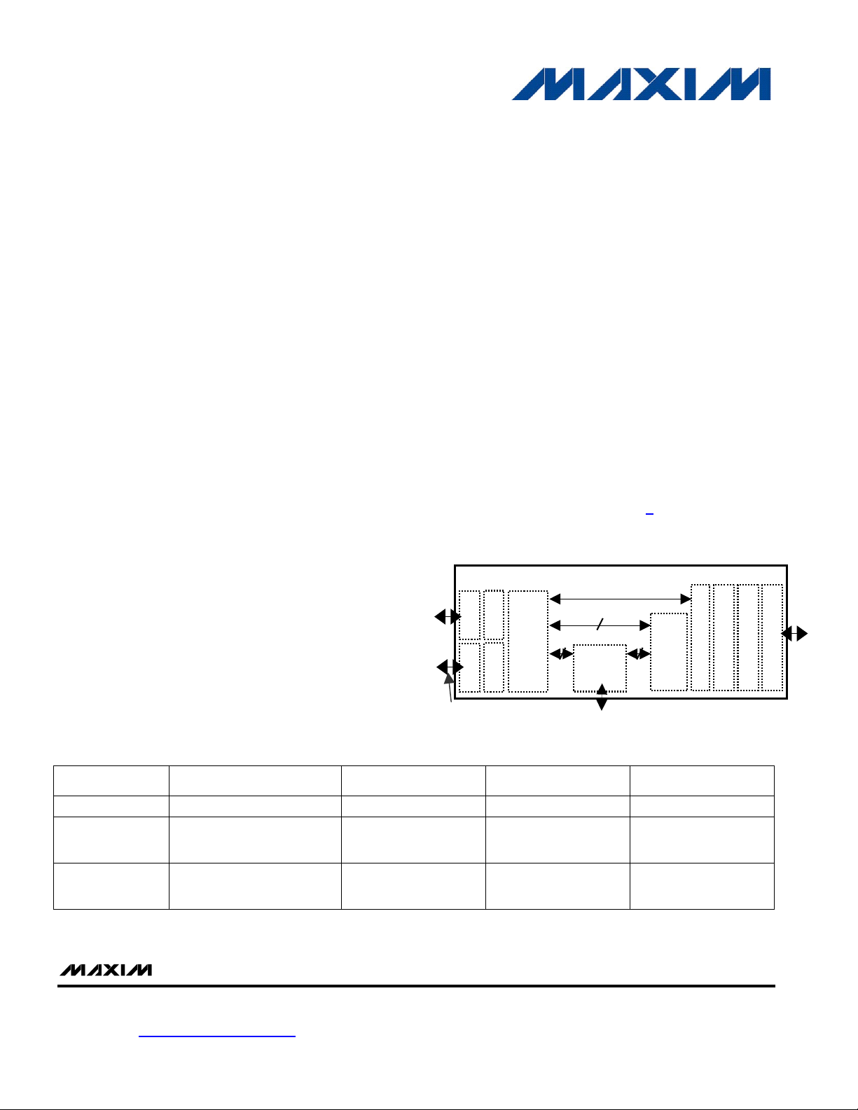
_________________________ Functional Diagram
DS33M30/M31/M33
Framer A
SERDES A
Mapper
DS3/E3
3
High-Order
Framer B
SERDES B
SerDes B AND FRAMER B ON
DS33M31/33 ONLY
Framers
1 VC-4
3x VC-3
3
DS3 ADD/DROP (DS33M33 ONLY)
LCAS
VCAT /
GFP / HDLC / LAPS
Advanced OAM
Traffic Mgmt
Ethernet MAC
______________________________________________________________________________Ordering Information
PART
DS33M30N+
DS33M31N+*
DS33M33N+
+Denotes a lead-free/RoHS-compliant package.
*Future product—contact factory for availability.
SUPPORTED EoS/EoPoS
MODES
EoS at VC-4 1 No 144 CSBGA
EoS at VC-4,
EoS at 3xVC-3,
EoPoS at 3xDS3
EoS at VC-4,
EoS at 3xVC-3,
EoPoS at 3xDS3
155Mbps PORTS EXT. DS3/E3 LINE PIN-PACKAGE
2 No 256 CSBGA
2 Yes (3) 256 CSBGA
SPI is a trademark of Motorola, Inc.
Maxim Integrated Products 1
Some revisions of this device may incorporate deviations from published specifications known as errata. Multiple
revisions of any device may be simultaneously available through various sales channels. For information about device
errata, go to: www.maxim-ic.com/errata
1-888-629-4642, or visit Maxim’s website at www.maxim-ic.com.
. For pricing, delivery, and ordering information, please contact Maxim Direct at
Page 2

___________________________________________________ DS33M30/M31/M33 ABRIDGED DATA SHEET
Table of Contents
1. GENERAL DESCRIPTION AND FEATURE HIGHLIGHTS.............................................................4
1.1 DEVICE FEATURE OVERVIEW ........................................................................................................... 5
1.2 TDM FEATURE OVERVIEW .............................................................................................................. 6
1.3 SONET/SDH..................................................................................................................................7
1.3.1 STS-3/STM-1 SerDes ............................................................................................................................ 7
1.3.2 STS-3/STM-1 Framer and Formatter..................................................................................................... 7
1.3.3 STS-3c/AU-4 Pointer Processing........................................................................................................... 8
1.3.4 STS-3c SPE/VC-4 Path Termination ..................................................................................................... 8
1.3.5 STS-3 Mux/Demux (DS33M31 and DS33M33 Only)............................................................................. 8
1.3.6 STS-1/AU-3/TU-3 Formatter and Framer (DS33M31 and DS33M33 Only) .......................................... 9
1.3.7 STS-1/AU-3/TU-3 Pointer Processing (DS33M31 and DS33M33 only)................................................ 9
1.3.8 STS-1/VC-3 Path Termination (DS33M31 and DS33M33 only).......................................................... 10
1.4 PDH (DS33M31 AND DS33M33 ONLY) ........................................................................................ 12
1.4.1 Add/Drop DS3/E3 Framer/Formatter (DS33M31 and DS33M33 only)................................................ 12
1.4.2 DS3/E3 Ethernet Mapping (DS33M31 and DS33M33 only)................................................................ 13
1.4.3 Line DS3/E3 Framer/Formatter (DS33M33 only) ................................................................................ 13
1.4.4 Loopback.............................................................................................................................................. 14
1.5 VIRTUAL CONCATENATION (VCAT) (DS33M31 AND DS33M33 ONLY)............................................14
1.5.1 SONET/SDH VCAT/LCAS ................................................................................................................... 14
1.5.2 PDH VCAT/LCAS................................................................................................................................. 15
1.6 ENCAPSULATION ...........................................................................................................................15
1.6.1 GFP-F Encapsulation (per ITU-T G.7041)........................................................................................... 15
1.6.2 HDLC Encapsulation............................................................................................................................ 15
1.6.3 cHDLC Encapsulation.......................................................................................................................... 15
1.6.4 X.86 Encapsulation Support ................................................................................................................ 15
1.7 ETHERNET FEATURE OVERVIEW ....................................................................................................15
1.7.1 Ethernet MAC Interface........................................................................................................................ 16
1.7.2 Ethernet Bridging for 10/100 ................................................................................................................ 16
1.7.3 Ethernet Traffic Classification .............................................................................................................. 16
1.7.4 Ethernet Traffic Profiling and Policing.................................................................................................. 16
1.7.5 Ethernet Traffic Scheduling.................................................................................................................. 16
1.7.6 Ethernet Control Frame Processing..................................................................................................... 16
1.7.7 Q-in-Q .................................................................................................................................................. 16
1.8 SDRAM INTERFACE......................................................................................................................16
1.9 CLOCK RATE ADAPTER (CLAD).....................................................................................................16
1.10 SPI SERIAL MICROPROCESSOR FEATURES................................................................................. 17
1.11 PARALLEL MICROPROCESSOR INTERFACE (DS33M31 AND DS33M33 ONLY)..............................17
1.12 TEST AND DIAGNOSTICS.............................................................................................................17
2. STANDARDS COMPLIANCE ........................................................................................................18
3. APPLICATIONS ............................................................................................................................. 20
Rev: 111908 2 of 20
Page 3

___________________________________________________ DS33M30/M31/M33 ABRIDGED DATA SHEET
List of Figures
Figure 1-1 TDM Functional Blocks .............................................................................................................................. 6
Figure 3-1. Example Application 1: EoS for DS33M30.............................................................................................. 20
Figure 3-2. Example Application 2: EoPoS for DS33M31 Interworking with EoP in DS33X162 Family of Devices .20
Figure 3-3. Example Application 3: EoPoS Transport for DS33M33 with Integrated Ethernet and PDH Services .. 20
List of Tables
Table 1-1. Product Selection Matrix............................................................................................................................. 5
Table 1-2. Summary of Mapping Functions................................................................................................................. 5
Table 2-1. Standards Compliance Summary............................................................................................................. 18
Rev: 111908 3 of 20
Page 4

___________________________________________________ DS33M30/M31/M33 ABRIDGED DATA SHEET
1. General Description and Feature Highlights
The DS33M30 family of devices provides interconnection and mapping functionality between Ethernet and
SONET/SDH networking elements. The product family includes three devices with differing features:
• DS33M30: One GMII mapped to STS-3c/VC-4 in a compact 10mm package.
• DS33M31: One GMII/MII mapped to a protected interface, with higher order EoS and EoPoS.
• DS33M33: One GMII/MII mapped to a protected interface, with higher order EoS, EoPoS and DS3/E3
add/drop mux.
All devices in the product family contain an Ethernet MAC port, one or two STS-3/STM-1 SerDes ports with the
LVDS/LVPECL interface, one or three GFP-F/HDLC/cHDLC/X.86 (LAPS) protocol encapsulators, one or three
higher order SONET/SDH mappers, a DDR SDRAM interface, and a local bus port for control/status. Ethernet
traffic is encapsulated with GFP-F, HDLC, cHDLC, or X.86 (LAPS) protocol to be transmitted onto the STS-3/
STM-1 interface. The family receives encapsulated Ethernet frames from the SerDes receiver interface and
transmits the de-encapsulated frames onto the Ethernet port.
With the smallest footprint, the DS33M30 contains the smallest feature set in the product family. It performs EoS
higher order mapping of Ethernet frames into a single STS-3c SPE or VC-4. The DS33M30 has one 1000Mbps
(GbE) port with GMII interface. The DS33M30 supports Ethernet OAM insert/extract capability, QoS Priority
Scheduling, VLAN processing, and committed information rate (CIR)-based policers for the delivery of carrier
Ethernet services.
The DS33M31 and DS33M33 expand on the features of the DS33M30 with additional mapping capabilities. They
support next-generation Ethernet over SONET/SDH in virtually concatenated higher order containers as well as
Ethernet-over-PDH-over-SONET/SDH (EoPoS) at the DS3/E3 level. They have an Ethernet interface that can be
configured as a 10/100Mbps MII/RMII port or a 1000Mbps (GbE) GMII port. They integrate four
mapping/demapping functions:
• SONET/SDH mapping: STS-1/VC-3 to STS-3/STM-1; or TU-3 to VC-4 to STM-1
• PDH mapping: DS3/E3 to STS-1/VC-3 (or TUG-3/VC-4);
• EoS higher order mapping: Ethernet to STS-1/VC-3 (or TU-3); and
• EoPoS mapping: Ethernet to DS3/E3 to STS-1/VC-3 (or TUG-3/VC-4).
At the STS-3/STM-1 side, the DS33M31 and DS33M33 devices interface to an STS-3/STM-1 signal through dual
serial-data buses operating at the rate of 155.52Mbps. This allows the implementation of a protected SONET/SDH
at PHY layer. Each serializer/deserializer (SerDes) is supported with independent STS-3/STM-1 framer.
The DS33M33 supports all the features of the DS33M30 and DS33M31, with additional line interfaces for up to
three add/drop DS3/E3 tributaries.
The SerDes interfaces, with LVDS/LVPECL, can be seamlessly connected to commercially available optical
transceivers.
Microprocessor control can be accomplished through an 8/16-bit local bus or SPI bus. The family contains a
125MHz DDR SDRAM controller and interfaces to a 32-bit-wide 256Mb DDR SDRAM through a 16-bit data bus.
The DDR SDRAM is used to buffer data through the Ethernet and STS-3/STM-1 ports.
The power supplies consist of a 1.8V core supply, a 2.5V DDR SDRAM supply, and 3.3V I/O supply.
Rev: 111908 4 of 20
Page 5
___________________________________________________ DS33M30/M31/M33 ABRIDGED DATA SHEET
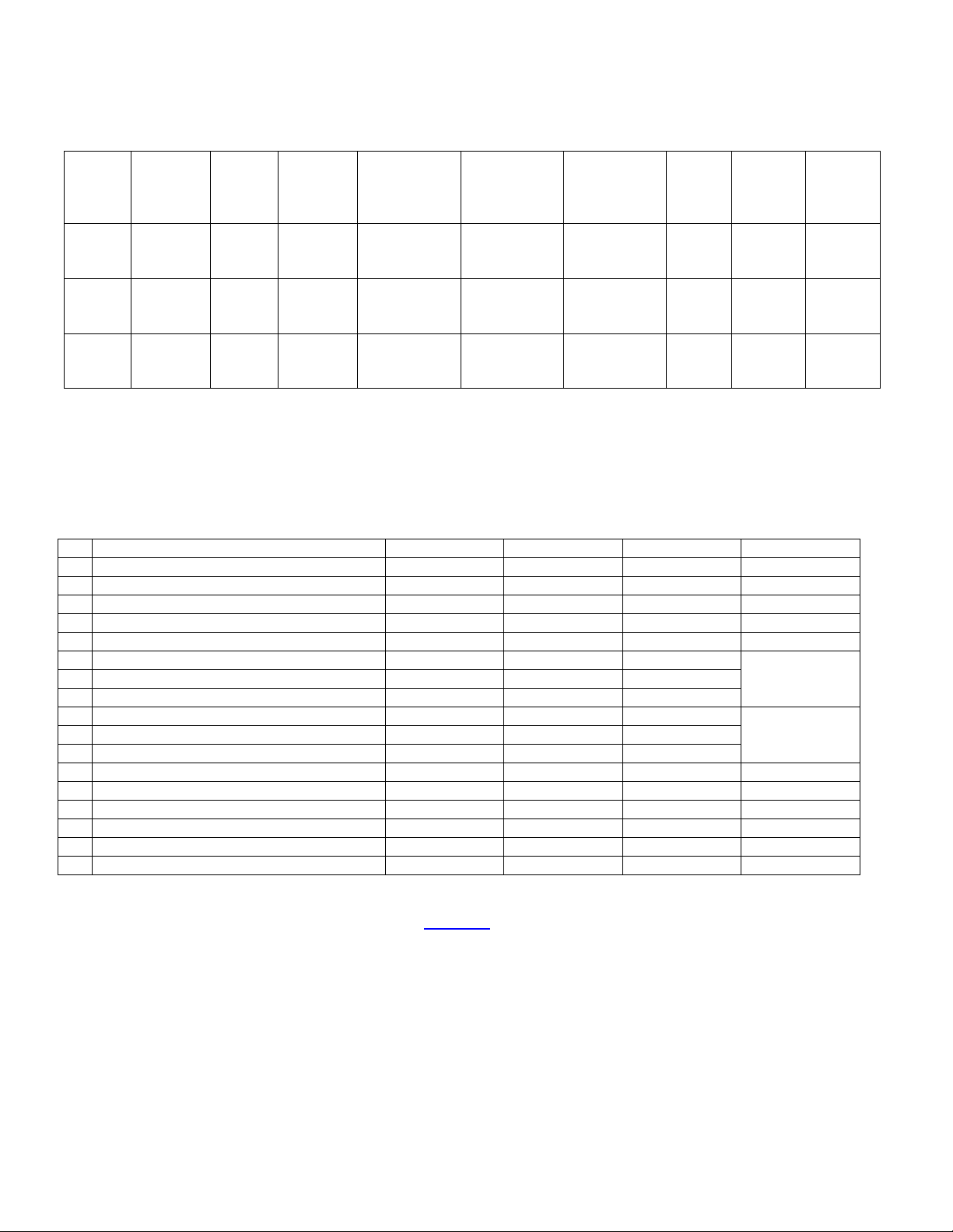
Table 1-1. Product Selection Matrix
PART
DS33M30
DS33M31
DS33M33
Note: The number of members for a VCG in the DS33M31 and DS33M33 can be 1, 2, or 3.
ETHERNET
PORT
1 GbE
1 (10/100,
GbE)
1 (10/100,
GbE)
STS-3/
STM-1
PORT
1 0 EoS NA Y 1 SPI
2 (1+1
protected)
2 (1+1
protected)
PDH
(DS3/E3)
PORT
0 EoS, EoPoS Y Y 3
3 EoS, EoPoS Y Y 3
ETHERNET
MAPPING
VLAN
FORWARDING
SUPPORT
PRIORITY
FORWARDING
SUPPORT
VCAT
GROUPS
(VCGS)
μP
CONTROL
SPI or
Parallel
SPI or
Parallel
PACKAGE
10mm, 144
CSBGA
17mm, 256
CSBGA
17mm, 256
CSBGA
1.1 Device Feature Overview
Note: See the glossary section (in the full data sheet) for the descriptions of terms used in this
documentation, especially for the terms referring to the ports, blocks, and directions.
Table 1-2. Summary of Mapping Functions
1 Ethernet > STS-3c > STS-3 x x x —
2 Ethernet > AU-4 > STM-1 x x x —
3 Ethernet > STS-1 > STS-3 — x x —
4 Ethernet > AU-3 > STM-1 — x x —
5 Ethernet > TU-3 > AU-4 > STM-1 — x x —
6 Ethernet > DS3 > STS-1 > STS-3 — x x
7 Ethernet > DS3 > AU-3 > STM-1 — x x
8 Ethernet > DS3 > TU-3 > AU-4 > STM-1 — x x
9 Ethernet > E3 > STS-1 > STS-3 — x x
10 Ethernet > E3 > AU-3 > STM-1 — x x
11 Ethernet > E3 > TU-3 > AU-4 > STM-1 — x x
12 DS3 > STS-1 > STS-3 — — x —
13 DS3 > AU-3 > STM-1 — — x —
14 DS3 > TU-3 > AU-4 > STM-1 — — x —
15 E3 > STS-1 > STS-3 — — x —
16 E3 > AU-3 > STM-1 — — x —
17 E3 > TU-3 > AU-4 > STM-1 — — x —
The DS33M30 family of devices offer the following features:
MAPPING FUNCTIONS “>” DS33M30 DS33M31 DS33M33 NOTES
Without
external DS3
port
Without
external E3
port
• Supports the mapping protocols as listed in
Table 1-2.
• Supports single 10/100/1000Mbps Ethernet interface
• STS-3/STM-1 interface operating at 155.52Mbps
• Supports two transmit timing modes for STS-3/STM-1 port(s):
• Loop timing (transmit timing reference = receive timing)
• Local timing (transmit timing reference = CLAD timing)
• Supports three transmit timing modes for Line DS3/E3 ports: (DS33M33)
• Loop timed (transmit timing reference = receive timing)
• Line timed (or thru timed) (transmit timing reference = Drop DS3/E3 thru timing)
• Local timed (transmit timing reference = CLAD timing)
• Certain clock, data, and control signals can be inverted to allow a glueless interface to other devices
• Certain port can be put into a low-power standby mode when not being used
Rev: 111908 5 of 20
Page 6
___________________________________________________ DS33M30/M31/M33 ABRIDGED DATA SHEET
• Manual or automatic one-second update of performance monitoring counters
• Single reference clock for all data rates using internal clock rate adapter (CLAD)
• Detection of loss of transmit clock and loss of receive clock
• Supports two packages:
• 10mm, 144-pin CSBGA Package (DS33M30)
• 17mm, 256-pin CSBGA Package (DS33M31/DS33M33)
• 1.8V, 2.5V, 3.3V supplies
• IEEE 1149.1 JTAG boundary scan
• Software access to device ID and silicon revision
• Development support includes evaluation kit, driver source code, and reference designs
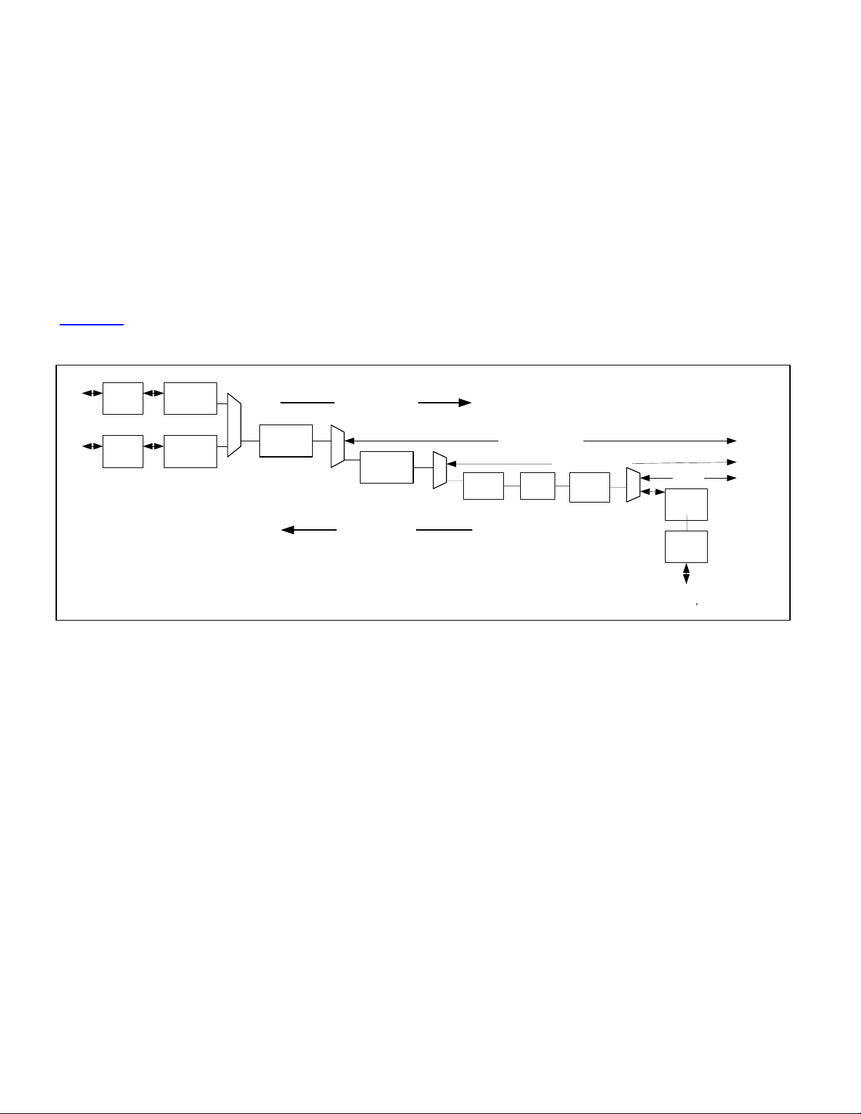
1.2 TDM Feature Overview
Figure 1-1 describes the TDM side feature.
Figure 1-1. TDM Functional Blocks
SERDES
SERDES
STS-3/STM-1
Side
STS-3
Section/Line
Termination
STS-3
Section/Line
Termination
M
U
STS-3 Path
X
Termination
(VC-4)
M
U
X
STS-1 Path
Termination
(VC-3)
M
U
X
EoS (VC-4/STS-3c)
DS3/E3
MAPPER
EoS (VC-3/STS-1)
DS3/E3
Desync
Add/Drop
DS3/E3
Framer
M
U
X
Add Direction
line coder
Drop Direction
to
Encapsulated
Ethernet
EoPoS
Line
DS3/E3
Framer
B3ZS/
HDB3
Line DS3/E3 side
• Supports M23 DS3, C-bit DS3, G.751 E3, and G.832 E3 facilities
• Mapping/demapping of three DS3/E3 tributaries to/from STS-3/STM-1 through STS-1 or AU-3 or TU-3/AU-4
• Fully integrated and compliant DS3/E3 mapper/demapper and synchronizers/desynchronizers per
Telcordia, ANSI, and ITU standards
• High speed DS3/E3/STS-1/STS-3 overhead insertion/extraction with full access to all overhead bytes
• Full-featured DS3/E3/STS-1/STS-3 defect and performance monitoring (PM) support Large PM counters
for accumulation intervals up to one second
• Loopback capabilities at both STS-3/STM-1 side and line DS3/E3 side
• Dual STS-3/STM-1 155.52Mbps serial interfaces with receive clock recovery and transmit clock synthesis
• From a single reference clock the CLAD (cLock rate adapter) generates clock references for DS3
(44.736MHz), E3 (34.368MHz), and/or STS-3/STM-1 reference (77.76/19.44MHz)
Rev: 111908 6 of 20
Page 7

___________________________________________________ DS33M30/M31/M33 ABRIDGED DATA SHEET
1.3
SONET/SDH
1.3.1 STS-3/STM-1 SerDes
• SerDes with clock recovery at 155.52Mbps interface for STS-3/STM-1 data stream
• LVDS/LVPECL levels for glueless interconnect to 155.52Mbps optical transceiver device
1.3.2 STS-3/STM-1 Framer and Formatter
1.3.2.1 STS-3/STM-1 Formatter with Transport Overhead Insertion
• User-configurable scrambling for transmit STS-3/STM-1 bit stream
• User-configurable TOH bytes insertion for framing (A1, A2), Section trace (J0), Section BIP-8 (B1), Section
orderwire (E1), Section user channel (F1), Section Data Communication Channel (DCC) (D1-D3), STS-1
pointers (H1, H2, H3), Line BIP-8 (B2), automatic protection switching (APS) channel (K1, K2), Line DCC
(D4-D12), synchronization status message (S1), line Remote Error Indication (REI) (M1), and line
orderwire (E2). Note: B1 and B2 are configured as error masks
• Automatic calculation and insertion of Section BIP-8 (B1) and Line BIP-8 (B2)
• User configurable insertion of AIS-P, and AIS-L
• Programmable generation of H1, H2, and H3 bytes as an error mask
• All TOH bytes can be inserted from the associated transmit STS-3 transport overhead input port or
software accessible internal registers
• Automatic or manual generation of line remote error indication (REI-L) and line remote defect indication
(RDI-L)
• Programmable insertion of framing errors, B1 errors, B2 errors, and invalid pointer
• Insertion of HDLC data stream into section DCC (D1-D3), line DCC (D4-D12), TOH DCC (D1-D12), or
section user channel (F1)
• Insertion of trace ID message into section trace (J0)
1.3.2.2 STS-3/STM-1 Framer with Transport Overhead Extraction
• Frame synchronization for STS-3 compliant to GR-253 so that SEF defect is not detected more than an
average of once every six minutes in the presence of STS-1 BER of 10-3
• Optional descrambler of incoming STS-1 data stream with polynomial of 1+x6+x7
• Extraction of all TOH bytes (per LTE requirement): Framing (A1, A2), Section trace (J0), Section BIP-8
(B1), Section orderwire (E1), Section user channel (F1), Section Data Communication Channel (DCC) (D1D3), STS-1 pointers (H1, H2, H3), Line BIP-8 (B2), automatic protection switching (APS) channel (K1, K2),
Line DCC (D4-D12), synchronization status message (S1), Line Remote Error Indication (REI) (M1), and
Line orderwire (E2)
• All TOH bytes are presented on the associated receive STS-3 transport overhead output port and software
accessible internal registers
• Detection of STE and LTE defects including LOS, LOF, SEF, COFA, and AIS-L
• Fully programmable automatic downstream path AIS (AIS-P) insertion upon detection of LOS, LOF, TIM-S,
and/or AIS-L
• Detection of STE and LTE defects including RDI-L, APS unstable, and sync message change (S1)
• Detection and accumulation of framing errors (A1/A2), OOF occurrences, section BIP-8 (B1) errors (bit or
block basis), line BIP-8 (B2) errors (bit or block basis), and line remote error indications (REI-L)
• Extraction of HDLC data stream from Section DCC (D1-D3), Line DCC (D4-D12), TOH DCC (D1-D12), or
Section user channel (F1)
• Extraction of trace ID message from Section trace (J0)
• Two line BIP-8 parity (B2) bit error rate (BER) measurement circuits with separate software programmable
detection and clearing settings
Rev: 111908 7 of 20
Page 8

___________________________________________________ DS33M30/M31/M33 ABRIDGED DATA SHEET
1.3.3 STS-3c/AU-4 Pointer Processing
1.3.3.1 STS-3c/AU-4 Pointer Generation
• AU-4 pointer generation using the associated Add STS-3/STM-1 clock
• Pointer generation of outgoing pointer values (H1/H2) per ITU G.707 specifications
• Generation of AU-4 pointer bytes (H1, H2, and H3) and insertion of the VC-4 POH
• User-configurable automatic or manual generation of AIS-P
• Generation of an unequipped indication (“all zero” path (payload data and POH) with valid J1, B3, and G1)
• Comprehensive software programmable pointer (H1, H2) diagnostics
1.3.3.2 STS-3c/AU-4 Pointer Interpretation
• AU-4 pointer interpretation using the Drop STS-3/STM-1 clock
• Pointer interpretation per ITU G.707 specifications
• Extraction of AU-4 pointer bytes (H1, H2, and H3) and the VC-4 POH
• Detection of alarm defects including LOP and “all ones” pointer (AIS-P)
• Detection and accumulation of incoming pointer increments, decrements, changes, and new pointers
1.3.4 STS-3c SPE/VC-4 Path Termination
1.3.4.1 STS-3c SPE/VC-4 Path Overhead Generation
• Generation of all POH bytes including Path trace ID (J1), Path BIP-8 (B3), Path signal label (C2), Path
status (G1), Path user byte (F2), Path concatenation indicator (H4), and Path growth (Z3, Z4, and Z5)
• All POH bytes can be inserted from either the VC-4 POH input port or software accessible internal registers
• User configurable automatic or manual generation of PTE defects including RDI-P and ERDI-P
• Programmable error insertion of B3 and REI errors
• Insertion of HDLC data stream into path user byte (F2)
• Insertion of path trace ID into path trace byte (J1)
1.3.4.2 STS-3c SPE/VC-4 Path Overhead Reception and Monitoring
• Monitoring of all POH bytes including Path trace ID (J1), Path BIP-8 (B3), Path signal label (C2), Path
status (G1), Path user byte (F2), Path concatenation indicator (H4), and Path growth (Z3, Z4, and Z5)
• All POH bytes are presented to the VC-4 POH output port and software accessible internal registers
• PTE defect detection: PLM-P, PLU-P, UNEQ-P, PDI-P, RDI-P, and Enhanced RDI-P (ERDI-P)
• Detection and accumulation of Path BIP-8 (B3) errors and Path REI errors (part of G1) on a bit or block
basis
• Two POH B3 bit-error rate (BER) measurement circuits with separate software programmable detection
and clearing thresholds
• Extraction of HDLC data stream from path user byte (F2)
• Extraction of path trace ID from path trace byte (J1)
1.3.4.3 STS-3c SPE/VC-4 Payload Mapper/Demapper
• Mapping of Ethernet traffic into/out of VC-4 payload (C-4).
1.3.5 STS-3 Mux/Demux (DS33M31 and DS33M33 Only)
1.3.5.1 STS-3 Mux
• Multiplexing of three TU-3 data streams (or ports) into a C-4 per ITU G.707
• Multiplexing of three STS-1/AU-3 data streams (or ports) into an STS-3/STM-1 per ITU G.707 and
Telcordia GR-253
1.3.5.2 STS-3 DeMux
• Demultiplexing of three TU-3 data streams (or ports) from a C-4 per ITU G.707
• Demultiplexing of three STS-1/AU-3 data streams (or ports) from an STS-3/STM-1 per ITU G.707 and
Telcordia GR-253
Rev: 111908 8 of 20
Page 9

___________________________________________________ DS33M30/M31/M33 ABRIDGED DATA SHEET
1.3.6 STS-1/AU-3/TU-3 Formatter and Framer (DS33M31 and DS33M33 Only)
1.3.6.1 STS-1/AU-3 Formatter with Transport Overhead Insertion
• User-configurable scrambling for transmit STS-1 data stream using a polynomial of 1 + x6 + x7
• Generation of all TOH bytes (per LTE requirement) including framing (A1, A2), Section trace (J0), Section
BIP-8 (B1), Section orderwire (E1), Section user channel (F1), Section Data Communication Channel
(DCC) (D1-D3), STS-1 pointers (H1, H2, H3), line BIP-8 parity (B2), automatic protection switching (APS)
channel (K1, K2), Line DCC (D4-D12), synchronization status message (S1), Line Remote Error Indication
(REI) (M1), and line orderwire (E2) Note: B1 and B2 are configured as error masks
• Calculation and insertion of Section BIP-8 (B1) and Line BIP-8 (B2)
• Programmable insertion of AIS-P, and AIS-L
• Programmable generation of H1, H2, and H3 bytes as an error mask
• All TOH bytes can be inserted from the associated transmit STS-1 transport overhead input port or
software accessible internal registers
• Automatic or manual generation of Line remote error indication (REI-L) and Line remote defect indication
(RDI-L)
• Programmable insertion of framing errors, B1 errors, B2 errors, and invalid pointer
• Insertion of HDLC data stream into Section DCC (D1-D3), Line DCC (D4-D12), TOH DCC (D1-D12), or
Section user channel (F1)
• Insertion of trace ID message into Section trace (J0)
1.3.6.2 STS-1/AU-3 Framer with Transport Overhead Extraction
• User-configurable descrambler of incoming STS-1 data stream with polynomial of 1 + x6 + x7
• Extraction of all TOH bytes (per LTE requirement): Framing (A1, A2), Section trace (J0), Section BIP-8
(B1), Section orderwire (E1), Section user channel (F1), Section Data Communication Channel (DCC) (D1D3), STS-1 pointers (H1, H2, H3), Line BIP-8 (B2), automatic protection switching (APS) channel (K1, K2),
Line DCC (D4-D12), synchronization status message (S1), Line Remote Error Indication (REI) (M1), and
Line orderwire (E2)
• All TOH bytes are presented on the associated receive STS-1 transport overhead output port and software
accessible internal registers
• Detection of STE and LTE defects including LOS, LOF, SEF, COFA, and AIS-L
• Fully programmable automatic downstream path AIS (AIS-P) insertion upon detection of LOS, LOF, TIM-S,
and/or AIS-L
• Detection of STE and LTE defects including RDI-L, APS unstable, and sync message change (S1)
• Detection and accumulation of framing errors (A1/A2), OOF occurrences, section BIP-8 (B1) errors (bit or
block basis), line BIP-8 (B2) errors (bit or block basis), and line remote error indications (REI-L)
• Extraction of HDLC data stream from Section DCC (D1-D3), Line DCC (D4-D12), TOH DCC (D1-D12), or
Section user channel (F1)
• Extraction of trace ID message from Section trace (J0)
1.3.7 STS-1/AU-3/TU-3 Pointer Processing (DS33M31 and DS33M33 only)
1.3.7.1 STS-1/AU-3/TU-3 Pointer Generation
• Per STS-1/AU-3/TU-3 tributary pointer generation using the associated inbound Add STS-3/STM-1 clock
• Pointer generation per Telcordia GR-253-CORE and ITU G.707 specifications
• Generation of STS-1, AU-3, or TU-3 pointer bytes (H1, H2, and H3) and insertion of the STS-1 SPE/VC-3
POH
• Detection and accumulation of pointer increments, decrements, and changes
• User configurable automatic or manual generation of AIS-P
• Generation of an unequipped indication (“all zero” path (payload data and POH) with valid J1, B3, and G1)
• Comprehensive software programmable pointer (H1, H2) diagnostics (Performs a pointer increment
justification (PJC+), pointer decrement justification (PJC-), pointer change (PJC) to a programmable fixed
value (without NDF), or new pointer change (NDF) to a programmable fixed value (with NDF) via the
register interface)
• Regeneration/relaying of an incoming STS-1 “all-ones” pointer (AIS-P) within one-frame time (125μs )
• STS-1 SPE POH generation pass-through mode for STS-1 line terminating equipment (LTE) applications
Rev: 111908 9 of 20
Page 10

___________________________________________________ DS33M30/M31/M33 ABRIDGED DATA SHEET
1.3.7.2 STS-1/AU-3/TU-3 Pointer Interpreter
• Per STS-1/AU-3/TU-3 tributary pointer interpretation using the outbound Drop STS-3/STM-1 clock
• Pointer interpretation per Telcordia GR-253-CORE and ITU G.707 specifications
• Extraction of STS-1, AU-3, or TU-3 pointer bytes (H1, H2, and H3)
• Detection of defects including, LOP and “all-ones” pointer (AIS-P)
• Detection and accumulation of incoming pointer increments, decrements, changes, and new pointers
1.3.8 STS-1/VC-3 Path Termination (DS33M31 and DS33M33 only)
1.3.8.1 STS-1/VC-3 Path Overhead Generation
• Generation of all POH bytes including Path trace ID (J1), Path BIP-8 (B3), Path signal label (C2), Path
status (G1), Path user byte (F2), Path concatenation indicator (H4), and Path growth (Z3, Z4, and Z5)
• All POH bytes can be inserted from either the associated inbound Add STS-1/VC-3 POH input port or
software accessible internal registers
• Automatic or manual generation of PTE alarm defects including RDI-P and ERDI-P
• Programmable error insertion of B3 and REI errors
• Insertion of HDLC data stream into path user byte (F2)
• Insertion of path trace ID into path trace byte (J1)
1.3.8.2 STS-1/VC-3 Path Overhead Reception and Monitoring
• Termination of all POH bytes (per PTE requirement) including Path trace ID (J1), Path BIP-8 (B3), path
signal label (C2), Path status (G1), Path user byte (F2), path concatenation indicator (H4), and Path growth
(Z3, Z4, and Z5)
• All POH bytes presented on the associated STS-1 SPE/VC-3 POH output port and software accessible
internal registers
• Detection of PTE defects: PLM-P, PLU-P, UNEQ-P, PDI-P, RDI-P, and Enhanced RDI-P (ERDI-P)
• Detection and accumulation of path B3 and path REI errors (part of G1) on a bit or block basis
• Two POH B3 bit error rate (BER) measurement circuits with separate software programmable detection
and clearing thresholds
• Extraction of HDLC data stream from path user byte (F2)
• Extraction of path trace ID from path trace byte (J1)
1.3.8.3 STS-1/VC-3 Synchronizer
• Synchronization of STS-1 SPE/VC-3 to accommodate asynchronous payload through pointer justifications
• Accommodation of frequency offsets up to +100ppm between the SONET/SDH Telecom Bus reference
frequency of 77.76MHz and the line/tributary STS-1 frequency 51.84MHz
• Elastic store overflow and underflow conditions
• Selectable lock and fast lock modes of operation
• Programmable frequency out of range indication (±5, ±10, ±20, or ±40ppm).
• SONET mapping jitter conforming to GR-253 and GR-499 and SDH mapping jitter compliant to ITU G.825e
and O.172e
1.3.8.4 STS-1 SPE Payload Mapping
• Each STS-1 SPE can be mapped with Asynchronous DS3/E3 or Ethernet traffic. These two mapping
modes are mutually exclusive.
1.3.8.5 STS-1 SPE Ethernet Mapping/Demapping
• Mapping of Ethernet packets into STS-1 SPE
1.3.8.6 Async DS3/E3 Demapper/Desynchronizer
• Extraction of DS3/E3 data stream from an STS-1 SPE compliant to Telcordia GR-253 or VC-3 compliant to
ITU G.707
• Generation of a nominal rate E3 (34.368MHz) or DS3 (44.736MHz)
• Standard SONET STS-1 demapping for a DS3/E3 conforming with Telcordia GR-253 and GR-499
• Standard SDH VC-3 demapping for a DS3/E3 conforming to ITU-T G.707, G.825e, and O.172e
• All combinations of DS3 or E3 demapping configuration from STS-1, AU-3, or TU-3/AU-4 are possible
• Software configuration for SONET/SDH demapping on a per tributary basis
Rev: 111908 10 of 20
Page 11

___________________________________________________ DS33M30/M31/M33 ABRIDGED DATA SHEET
• Synchronization of DS3/E3 serial streams from SONET/SDH STS-1 SPE/VC-3 accommodating
asynchronous timing between the DS3/E3 line/tributary and the STS-3/STM-1 references, through
appropriate processing of bit stuffing and pointer justifications
• Full integration of the DS3/E3 desynchronization and PLL circuitry necessary to produce smooth DS3/E3
data and clock signals that meet the Telcordia (GR-253-CORE and GR-499-CORE), ANSI (T1-105.031994 and T1-105.03b-1997), and ITU (G.825e and O.172e) jitter and wander requirements. Desynchronize
circuitry includes clock smoother consisting of onboard analog/digital control modulators, analog/digital
filters, and frequency detectors
• Absorption of SONET/SDH pointer justifications and DS3/E3 payload bit stuffs in an elastic store, and
controlling outgoing clock phase using the smooth clock generator circuit with selectable lock and fast lock
modes of operation
• Tolerating frequency offsets up to ±200ppm between the inbound Add Telecom Bus clock (ACLK) and the
free-running DS3/E3 reference clocks generated by the internal Clock Rate Adapter
• Monitoring and detection of the stability of the recovered DS3 clocks with frequency offset indications of
±20, ±100, and ±200ppm and the elastic store FIFO underflow/overflow conditions. The elastic store has
an auto center mechanism that separates the read and write pointers under normal operating conditions
and after underflow/overflow events occur
• Programmable frequency out of range indication (±10, ±20, ±40, or ±100ppm)
• Selectable lock and fast lock modes of operation
• Maximum lock time for the smooth recovered/output DS3/E3 data and clock that is demapped from
SONET/SDH is 1.06ms (10 DS3, 24 G.751 E3, or nine G.832 E3 frames) (switch time to valid DS3 with a
smooth clock)
• Controls include enables/disables/settings for serial data type, and demapping mode
1.3.8.7 Async DS3/E3 Mapper/Synchronizer
• Synchronization of DS3/E3 serial streams to SONET/SDH STS-1 SPE/VC-3 accommodating
asynchronous timing between the DS3/E3 line/tributary and the STS-3/STM-1 references, through bit
stuffing
• Accommodation of frequency offsets up to +200ppm between the 155.52Mbps inbound add STS-3/STM-1
serial data stream and the 44.736/34.368MHz line/tributary DS3/E3 clock (RLCLKn)
• Elastic store overflow and underflow conditions
• Programmable frequency out of range indication (±10, ±20, ±40, or ±100ppm)
• SONET mapping jitter conforming to GR-253 and GR-499 and SDH mapping jitter compliant to ITU G.707,
G.825e and O.172e
• Mapping of DS3/E3 serial data stream into an STS-1 SPE compliant to Telcordia GR-253 or VC-3
compliant to ITU G.707
• Standard SONET STS-1 mapping for DS3/E3 conforming to Telcordia GR-253 and GR-499
• Standard SDH VC-3 mapping for DS3/E3 conforming to ITU-T G.707
• All combinations of DS3 or E3 mapping configuration into STS-1, AU-3, or TU-3/AU-4 are possible
• Software configuration for SONET/SDH mapping on a per tributary basis
• Software configuration for all fixed stuff bits to zeros or ones
• Controls include enables/disables/settings for mapping type, alarm insertion, stuff bits, frequency offset
(±100ppm to ±200ppm)
Rev: 111908 11 of 20
Page 12

___________________________________________________ DS33M30/M31/M33 ABRIDGED DATA SHEET
1.4 PDH (DS33M31 and DS33M33 Only)
There are two sets of DS3/E3 framer/formatters. Each set supports three independent DS3/E3 data streams (or
ports). The set interfaces directly to the Async DS3/E3 mapper called Add/Drop Framer/Formatter. The set
interfaces with external T3/E3 facilities are called Line Framer/Formatter The Add/Drop Framers reside in both the
DS33M31 and DS33M33 and are used for path monitoring the desynchronized DS3/E3 and test origination of the
PDH signals. The Line Framers, supported only in DS33M33, are used for path monitoring the received signals
from external facilities.
1.4.1 Add/Drop DS3/E3 Framer/Formatter (DS33M31 and DS33M33 only)
1.4.1.1 Drop DS3/E3 Framer
• Incorporation of drop DS3/E3 framers on a per port basis for far-end alarm detection and performance
monitor of DS3/E3 signals that are demapped from SONET/SDH STS-12/STM-4
• Frame synchronization for M23 DS3, C-bit Parity DS3, G.751 E3, and G.832 E3
• Detection of DS3 loss of frame (LOF), out of frame (OOF), out of multiframe (OOMF), severely error frame
(SEF), change of frame alignment (COFA), remote defect indication (RDI), alarm indication signal (AIS),
receive unframed all ones, idle signal, DS3 application ID bit, and DS3 format mismatch
• Detection of G.751 E3 LOF, OOF, COFA, remote alarm indication (RAI), and AIS
• Detection of G.832 E3 LOF, OOF, COFA, RDI, and AIS
• Detection and accumulation of F-bit errors, M-bit errors, FAS errors, FA1 and FA2 byte errors, OOF
occurrences, P-bit parity errors, C-bit parity errors, BIP-8 (bit or block basis) errors, far end block errors
(FEBE), and remote error indications (REI)
• Fully programmable automatic AIS insertion upon detection of OOF and/or AIS
• All DS3/E3 overhead fields are presented on the associated receive DS3/E3 overhead output port
• Extraction of HDLC data stream from DS3 path maintenance data link (PMDL), G.751 E3 national bit, or
G.832 E3 NR or GC bytes
• Extraction of trail trace access point identifier from G.832 E3 TR byte
1.4.1.2 Add DS3/E3 Formatter (Optional)
• Insertion of all overhead for M23 DS3, C-bit parity DS3, G.751 E3, and G.832 E3
• Manual generation of AIS and DS3 idle signals
• Automatic or manual generation of RDI/RAI and FEBE/REI
• Programmable error insertion of framing errors, parity errors, and FEBE/REI errors
• All DS3/E3 overhead fields can be sourced from the external transmit DS3/E3 overhead input port
• Insertion of HDLC data stream into DS3 path maintenance data link (PMDL), G.751 E3 national bit, or
G.832 E3 NR or GC bytes
• Insertion of trail trace access point identifier into G.832 E3 TR byte
• M23 DS3 C-bits programmable as payload or overhead
• Formatter pass-through mode with programmable DS3 P-bit correction for DS3/E3 line terminating
equipment (LTE) applications
1.4.1.3 HDLC Controller
• Two controllers per port for DS3 path maintenance data link (PMDL), G.751 national bit (Sn), G.832
NR/GC, or STS-1 DCCs (D1-D3 and/or D4-12), or STS-1/VC-3 path user channel (F1 or F2)
• A controller for each optional VC-4 path user channels (F2)
• 256-byte receive and transmit FIFOs
• Handles all of the normal Layer 2 tasks including zero stuffing/destuffing, FCS generation/checking, abort
generation/checking, flag generation/detection, and byte alignment
• Programmable high and low water marks for the transmit and receive FIFOs
• Rx data is forced to all ones during LOS, LOF, and AIS detection to eliminate false packets
Rev: 111908 12 of 20
Page 13

___________________________________________________ DS33M30/M31/M33 ABRIDGED DATA SHEET
1.4.1.4 Trace Identifier Controller
• Three trace identifier controllers per port for
o the line/tributary side G.832 trail trace (TR),
o the system/trunk side G.832 trail trace (TR), and system/trunk side STS-1/VC-3 path trace (J1) in
DS3/E3 mode, or
o the STS-1 section trace (J0), line/tributary side STS-1 path trace (J1), and system/trunk side STS-
1/VC-3 path trace (J1) in STS-1 mode.
• A trace identifier controller for each optional VC-4 path trace (J1)
• Software programmable trace identifier mode: 16-byte trail trace access point or 64-byte path trace
• Extraction and storage of the incoming trace identifier message in a 64/16-byte receive register
• Software programmable incoming expected trace identifier message
• Software programmable outgoing trace identifier message or idle trace identifier message
• Incoming trace identifier mismatch, unstable, idle, and change indications
• Insertion of the outgoing trace identifier message from a 64/16-byte transmit register
1.4.1.5 Bit Error Rate Tester (BERT)
• One BERT per port software programmable for insertion
o Into DS3/E3 payload toward DS3/E3 Line interface, or
o Into DS3/E3 payload mapped to STS-1 toward STS-3/STM-1 interface, or
o Into STS-1 payload toward STS-3/STM-1 interface
• Generates and detects pseudo-random patterns of length 2n – 1 (n = 1 to 32) and repetitive patterns from
1 to 32 bits in length
• Supports pattern insertion/extraction in DS3/E3 payload, or entire data stream
• Supports pattern insertion/extraction in STS-1/VC-3/VC-4 payload, or entire STS-1 SPE/AU-3/AU-4
• Large 24-bit error and 32-bit bit counters allow testing over long periods without host intervention
• Errors can be inserted in BERT patterns for diagnostic purposes (single bit errors or specific bit-error rates)
• Pattern synchronization even in the presence of 10-3 bit error rate
1.4.2 DS3/E3 Ethernet Mapping (DS33M31 and DS33M33 only)
• Mapping/Demapping of encapsulated Ethernet packets into/out-of the payload of the Add/Drop DS3/E3.
1.4.3 Line DS3/E3 Framer/Formatter (DS33M33 only)
1.4.3.1 Line DS3/E3 Framer
• Frame synchronization for M23 DS3, C-bit Parity DS3, G.751 E3, and G.832 E3
• Detection of DS3 loss of signal (LOS), loss of frame (LOF), out of frame (OOF), out of multiframe (OOMF),
severely error frame (SEF), change of frame alignment (COFA), remote defect indication (RDI), alarm
indication signal (AIS), receive unframed all ones, idle signal, DS3 application ID bit, and DS3 format
mismatch
• Detection of G.751 E3 LOS, LOF, OOF, COFA, remote alarm indication (RAI), and AIS
• Detection of G.832 E3 LOS, LOF, OOF, COFA, RDI, and AIS
• Detection and accumulation of F-bit errors, M-bit errors, FAS errors, FA1 and FA2 byte errors, OOF
occurrences, P-bit parity errors, C-bit parity errors, BIP-8 (bit or block basis) errors, far end block errors
(FEBE), and remote error indications (REI)
• Fully programmable automatic AIS insertion upon detection of LOS, OOF, and/or AIS
• All DS3/E3 overhead fields are presented on the associated receive DS3/E3 overhead output port
• Extraction of HDLC data stream from DS3 path maintenance data link (PMDL), G.751 E3 national bit, or
G.832 E3 NR or GC bytes
• Extraction of FEAC data from DS3 FEAC bit or G.751 E3 alarm bit
• Extraction of trail trace access point identifier from G.832 E3 TR byte
• Framer pass-through mode for clear channel applications and externally defined frame formats
Rev: 111908 13 of 20
Page 14

___________________________________________________ DS33M30/M31/M33 ABRIDGED DATA SHEET
1.4.3.2 Line DS3/E3 Formatter (Optional)
• Insertion of all overhead for M23 DS3, C-bit parity DS3, G.751 E3, and G.832 E3
• Automatic or manual generation of RDI/RAI and FEBE/REI
• Fully programmable automatic AIS insertion upon detection of an outbound Drop Telecom Bus alarm
indication (DALARM), VC-4 LOP, VC-4 AIS-P, STS-1/AU-3/TU-3 LOP, and/or STS-1 SPE/VC-3 AIS-P
• Automatic generation of RDI/RAI and FEBE/REI
• Programmable error insertion of framing errors, parity errors, and FEBE/REI errors
• All DS3/E3 overhead fields can be sourced from the externally controlled transmit DS3/E3 overhead input
port
• Insertion of HDLC data stream into DS3 path maintenance data link (PMDL), G.751 E3 national bit, or
G.832 E3 NR or GC bytes
• Insertion of FEAC data into DS3 FEAC bit or G.751 E3 alarm bit
• Insertion of trail trace access point identifier into G.832 E3 TR byte
• M23 DS3 C-bits programmable as payload or overhead
• Formatter pass-through mode with programmable DS3 P-bit correction for DS3/E3 line terminating
equipment (LTE) applications
1.4.3.3 FEAC Controller
• One controller per port at the Receive DS3/E3 framer and Transmit DS3/E3 Formatter
• Designed to handle multiple FEAC codewords without Host intervention
• Receive FEAC automatically validates incoming codewords and stores them in a 4-byte FIFO
• Transmit FEAC can be programmed to send one code word, one code word continuously, or two different
code words back-to-back to send DS3 Line Loopback commands
• Terminates the FEAC port in DS3 C-Bit Parity mode or either the Sn or A bit in G.751 E3 mode
1.4.3.4 Receive B3ZS/HDB3 Decoder
• Software programmable B3ZS/HDB3 or AMI decoding
• Detection of loss of signal (LOS) and receipt of B3ZS/HDB3 codewords
• Detection and accumulation of bipolar violations (BPV), code violations (CV), and excessive zeroes
occurrences (EXZ)
1.4.3.5 Transmit B3ZS/HDB3 Encoder
• Software programmable B3ZS/HDB3 or AMI decoding
• Programmable insertion of bipolar violations (BPV), code violations (CV), and excessive zeroes
occurrences (EXZ)
1.4.4 Loopback
• Line analog terminal loopback—ALB (transmit LIU/line output to receive LIU/line input)
• Line facility loopback—LLB (receive LIU/line output to transmit LIU/line input)
• Diagnostic terminal loopback—DLB (transmit formatter output to receive framer input)
• Payload loopback—PLB (receive framer output to transmit formatter input)
• STS-3/STM-1 interface loopback—SLB (Outbound Drop Telecom Bus input to Inbound Add Telecom Bus
output)
• Simultaneous line facility loopback (LLB) and diagnostic terminal loopback (DLB)
• Optionally AIS (unframed all-ones, UA1, or framed AIS) can be inserted in the normal data stream during a
line (LLB), framer diagnostic (DLB), payload (PLB), or STS-3/STM-1 loopback (SLB) mode
1.5 Virtual Concatenation (VCAT) (DS33M31 and DS33M33 only)
• Up to three VCG engines
1.5.1 SONET/SDH VCAT/LCAS
• Supports up to three VC-3 in one VCG (per ITU-T G.707)
• Supports differential delay compensation up to 200ms
Rev: 111908 14 of 20
Page 15

___________________________________________________ DS33M30/M31/M33 ABRIDGED DATA SHEET
1.5.2 PDH VCAT/LCAS
• Supports up to three DS3/E3 in one VCG (per ITU-T G.7043/G.7042)
• Supports differential delay compensation up to 200ms
1.6 Encapsulation
• Up to three encap/decap engines for various port configurations
1.6.1 GFP-F Encapsulation (per ITU-T G.7041)
• GFP-F idle frame insertion and extraction
• Null header support
• cHEC-based frame delineation
43
• X
• Barker sequence scrambling and descrambling
• Supports CSF frame handling
• CRC-32 generation and verification
1.6.2 HDLC Encapsulation
• Programmable 16/32-bit FCS insertion/extraction
• Support for bit and byte stuffed operation
• Programmable address/control/PID fields
• Self-synchronizing X
• Valid and invalid frame counters
• Programmable inter-frame fill
• Frame filtering of FCS errors
• cHDLC support with SLARP extraction
+1 payload scrambling and descrambling
43
+1 packet scrambling
1.6.3 cHDLC Encapsulation
• Bit stuffing with address/control/PID/FCS fields
• Programmable interframe fill length
• Transparency processing
• Counters: number of received valid frames and erred frames
• Incoming frame discard due to FCS error, abort, or frame length longer than preset max
• Default maximum frame length is associated with the maximum PDU length of MAC frame
• Extract SLARP for external processor interpretation
1.6.4 X.86 Encapsulation Support
• Transmit Transparency Processing
• Receive rate adaptation removal
• Selectable X
43
+1 packet scrambling
• Valid and Invalid Frame counters
• Frame filtering of FCS errors
1.7 Ethernet Feature Overview
• Supports Single 10/100/1000Mbps Ethernet interfaces (Half or Full Duplex)
• WAN Packet field modifications (Header and FCS)
• Byte stuffed HDLC or GFP (Null or Linear) for any valid BW and VCG size
• Ethernet Frame modifications (Remove 14/18, VLAN/Q-in-Q and Ethernet FCS)
• LAN Frame Inspection for VLAN (Forwarding, Discarding, Extract), Extract, Priority Coding
• WAN Frame Inspection for VLAN (Forwarding, Extract), Extract
• Scheduler with options of strict priority or WRR
• Up to 200ms of differential delay using external DDR SDRAM
• Bridge Filtering for 10/100Mbps applications
• Policing based on per-port, per-COS, or per-multicast/broadcast type
Rev: 111908 15 of 20
Page 16

___________________________________________________ DS33M30/M31/M33 ABRIDGED DATA SHEET
1.7.1 Ethernet MAC Interface
• One E/FE/GbE port (MII/RMII/GMII)
• 10Mbps/100Mbps/1000Mbps data rates
• Support for DTE or DCE operation
• Half- and full-duplex flow control per IEEE 802.3
• Jumbo frame lengths up to 10KB for GbE
• 64-byte minimum frame size
• Ethernet management interface (MDIO)
• Supports applicable RMON (RFC2819) counters
• Promiscuous and broadcast discard modes
• OAM frames can be intercepted, processed by host software, and responses inserted
1.7.2 Ethernet Bridging for 10/100
• 4K address and VLAN ID lookup table for learning and filtering
• Programmable aging between one to 300 seconds in one-second intervals
1.7.3 Ethernet Traffic Classification
• Ingress classification according to Ethernet COS
• Programmable class map to four queues for each Ethernet port
1.7.4 Ethernet Traffic Profiling and Policing
• Ingress classification by PCP or DSCP
• Programmable class mapping to four queues
• Programmable bandwidth profiling at either the port level or per-class level
• Programmable bandwidth profiling for multicast and broadcast flows
• Policing with programmable CIR/CBS
• Nonconforming Ethernet frames discarded according to the configured BW profile
1.7.5 Ethernet Traffic Scheduling
• Programmable scheduler for Ethernet flows toward PDH port(s):
o Strict priority, or
o Weighted queuing
1.7.6 Ethernet Control Frame Processing
• Control frames, except PAUSE and OAM, are forwarded without processing
• PAUSE and OAM frames can be programmed to be intercepted, discarded or forwarded
1.7.7 Q-in-Q
• Programmable carrier VLAN tag insertion
1.8 SDRAM Interface
• Interface for up to 256Mb DDR SDRAM (JEDEC JESD79D compliant)
• Compatible with DDR266+
• 16-bit-wide data bus with dual edge transfers and auto refresh timing
• SDRAM interface clock output of 125MHz
• Direct connection to external DDR SDRAM
• Example devices: Micron MT46V16M16, Samsung K4H561638F and Hynix HY5DU561622CF
1.9 Clock Rate Adapter (CLAD)
• Creates DS3, E3, STS-1, and/or telecom bus clocks from single-input reference clock
• Input reference clock to CLAD can be 77.76, 51.84, 44.736, 34.368, or 19.44MHz
Rev: 111908 16 of 20
Page 17

___________________________________________________ DS33M30/M31/M33 ABRIDGED DATA SHEET
• Clocks can be used for LIU, jitter attenuator, and DS3 desynchronizer reference clocks and STS-1 transmit
clocks on per port basis
• Output four derived clocks for external component use, if needed
• Meets jitter and wander transmission clock requirements.
• Transmit (outbound) line/tributary LIU signals using internal CLAD meet Telcordia (DS3) and ITU (E3) jitter
and wander requirements
1.10 SPI Serial Microprocessor Features
• Operation up to 10Mbps
• Burst mode for multibyte read and write accesses
• Programmable clock polarity and phase
• Half-duplex operation gives option to connect SDI and SDO together externally to reduce wire count
1.11 Parallel Microprocessor Interface (DS33M31 and DS33M33 Only)
• Multiplexed or nonmultiplexed address bus modes
• 8-bit or 16-bit data bus modes
• Intel and Motorola bus compatible
• Ready handshake output signal
• Global reset input pin
• Global interrupt output pin
• Two programmable I/O pins per port
1.12 Test and Diagnostics
• IEEE 1149.1 JTAG support
• Diagnostic loopbacks
Rev: 111908 17 of 20
Page 18

___________________________________________________ DS33M30/M31/M33 ABRIDGED DATA SHEET
2. Standards Compliance
The DS33M30 family of products adhere to the applicable telecommunications standards. Table 2-1 provides the
specifications and relevant sections.
Table 2-1. Standards Compliance Summary
SPECIFICATION SPECIFICATION TITLE
ANSI
T1.102-1993
T1.105-2001
T1.105.02-2001
T1.105.03-1994
T1.105.03b-1997
T1.105.06-2001
T1.107-1995
T1.107a-1990
T1.231-1997
T1.231.03-2003
T1.231.04-2003
T1.404-1994
T1.646-1995
ETSI
ETS 300 337
ETS 300 417-1-1 Generic Functional Requirements for Synchronous Digital Hierarchy (SDH) equipment,
ETS 300 686
ETS 300 687
ETS 300 689
TBR 24
IETF
RFC 1662 PPP in HDLC-like Framing, July, 1994
RFC 2615 PPP over SONET/SDH; June 1999
RFC 2496 Definition of Managed Objects for the DS3/E3 Interface Type, January, 1999
RFC 2819 Remote Network Monitoring Management Information Base; May 2000
ISO
ISO 3309:1993
Digital Hierarchy – Electrical Interfaces
Synchronous Optical Network (SONET) -- Basic Description including Multiplex Structure,
Rates, and Formats
Synchronous Optical Network (SONET) – Payload Mappings
Synchronous Optical Network (SONET) – Jitter at Network Interfaces
Synchronous Optical Network (SONET) – Jitter at Network Interfaces – DS3 Wander
Supplement
Synchronous Optical Network (SONET) – Physical Layer Specifications
Digital Hierarchy – Formats Specification
Digital Hierarchy – Supplement to Formats Specifications (DS3 Format Applications)
Digital Hierarchy – Layer 1 In-Service Digital Transmission Performance Monitoring
DS3 – Layer 1 In-Service Digital Transmission Performance Monitoring
SONET – Layer 1 In-Service Digital Transmission Performance Monitoring
Network-to-Customer Installation – DS3 Metallic Interface Specification
Broadband ISDN – Physical Layer Specification for User-Network Interfaces Including
DS1/ATM
Transmission and Multiplexing (TM); Generic frame structures for the transport of various
signals (including Asynchronous Transfer Mode (ATM) cells and Synchronous Digital
Hierarchy (SDH) elements) at the ITU-T Recommendation G.702 hierarchical rates of 2 048
Kbit/s, 34 368 Kbit/s and 139 264 Kbit/s, Second Edition, June, 1997
January 1996
Business TeleCommunications; 34Mbit/s and 140Mbits/s digital leased lines (D34U, D34S,
D140U and D140S); Network interface presentation, 1996
Business TeleCommunications; 34Mbit/s digital leased lines (D34U and D34S); Connection
characteristics, 1996
Business TeleCommunications (BTC); 34 Mbit/s digital leased lines (D34U and D34S),
Terminal equipment interface, V 1.2.1, 2001-07
Business TeleCommunications; 34Mbit/s digital unstructured and structured lease lines;
attachment requirements for terminal equipment interface, 1997
Information Technology – Telecommunications & information exchange between systems –
High Level Data Link Control (HDLC) procedures – Frame structure, Fifth Edition, 1993
Rev: 111908 18 of 20
Page 19

___________________________________________________ DS33M30/M31/M33 ABRIDGED DATA SHEET
SPECIFICATION SPECIFICATION TITLE
ITU-T
G.703 11/01
G.704 10/98
Physical/Electrical Characteristics of Hierarchical Digital Interfaces
Synchronous Frame Structures Used at 1544, 6312, 2048, 8488 and 44 736 Kbit/s
Hierarchical Levels
G.707/Y.1322 Network node interface for the synchronous digital hierarchy (SDH) (10/2000)
G.751 11/88
Digital Multiplex Equipment Operating at the Third Order Bit Rate of 34,368 Kbit/s and the
Fourth Order bit Rate of 139,264 Kbit/s and Using Positive Justification
G.752 11/88
Characteristics Of Digital Multiplex Equipments Based On A Second Order Bit Rate Of 6312
Kbit/s And Using Positive Justification
G.775 11/94
Loss Of Signal (LOS) and Alarm Indication Signal (AIS) Defect Detection and Clearance
Criteria
G.783 02/04
G.823 03/00
Characteristics of synchronous digital hierarchy (SDH) equipment functional blocks
The Control of Jitter and Wander Within Digital Networks Which are Based on the 2048
Kbit/s Hierarchy
G.824 03/00
The Control of Jitter and Wander Within Digital Networks Which Are Based On The 1544
Kbit/s Hierarchy
G.825 03/00
The Control of Jitter and Wander Within Digital Networks Which Are Based On The
Synchronous Digital Hierarchy (SDH)
G.832 10/98
Transport of SDH Elements on PDH Networks – Frame and Multiplexing Structures
G.7041/Y.1303 Generic Framing Procedure (GFP) (08/2005)
G.7042/Y.1305 Link Capacity Adjustment Scheme (LCAS) for Virtual Concatenated signal (03/2006)
G.7043/Y.1343 Virtual Concatenation of PDH signals (07/2004)
G.8040/Y.1340 GFP Frame Mapping into PDH (09/2005)
O.150 05/96
General Requirements for Instrumentation for Performance Measurements on Digital
Transmission Equipment
O.151 10/92
O.161 11/88
O.162 10/92
Error Performance Measuring Equipment Operating at the Primary Rate and Above
In-Service Code Violation Monitors for Digital Systems
Equipment To Perform In-Service Monitoring on 2048, 8448, 34,368 and 139,264 Kbit/s
Signals
O.171 04/97
Timing Jitter And Wander Measuring Equipment For Digital Systems Which Are Based On
The Plesiochronous Digital Hierarchy (PDH)
O.172 03/01
Timing Jitter And Wander Measuring Equipment For Digital Systems Which Are Based On
The Synchronous Digital Hierarchy (SDH)
O.181 05/02
Equipment to assess error performance on STM-N interfaces
Q.921 ISDN User-Network Interface – Data Link Layer Specification (09/1997)
Y.1731 Y.1731 Ethernet OAM (05/2006)
X.86/Y.1323 Ethernet over LAPS (02/2001)
Telcordia
GR-253-CORE Synchronous Optical Network (SONET) Transport Systems: Common Generic Criteria, Issue
3, September 2000
GR-499-CORE Transport Systems Generic Requirements (TSGR): Common Requirements, Issue 2,
December 1998
GR-820-CORE Generic Digital Transmission Surveillance, Issue 1, November 1994
IEEE
802.3-2005 CSMA/CD access method and physical layer specifications.
802.1D-2004 MAC Bridge
802.1Q-2005 Virtual LANs
802.1v-2001 VLAN Classification by Protocol and port
802.1ag Ethernet OAM (extract/insert support) (draft 8.1)
IEEE Std 11491990
IEEE Standard Test Access Port and Boundary-Scan Architecture, (Includes IEEE Std 1149-
1993E) October 21, 1993
Other
RMII: Industry Implementation Agreement for “Reduced MII Interface”, Sept 1997
Rev: 111908 19 of 20
Page 20

___________________________________________________ DS33M30/M31/M33 ABRIDGED DATA SHEET
S33
3. Applications
• Ethernet Service Mux over SDH (EoS)—Higher Order
• Ethernet Service Backhaul over PDH over SDH (EoPoS)—E3/T3 Æ STS-1/VC3
• Ethernet Service Extension
• Integrated Access Device (IAD)—Dual Service with Data (Ethernet) and TDM (E3/DS3) Access
• Ethernet Access Concentrators
• MSPPs with EoS and EoP Support
• Base-Station Backhaul
• Microwave Radio Links
Figure 3-1. Example Application 1: EoS for DS33M30
ETH
SW
GbE
DS33M30
STM-1
SDH
ADM
STM-1
DS33M30
GbE
ETH
SW
Figure 3-2. Example Application 2: EoPoS for DS33M31 Interworking with EoP in DS33X162 Family of Devices
ETH
SW
E/FE/
GbE
DS33X11/
DS33X41
EoP
E3/T3
1~3 LINES,
1 VCG
SDH
ADM
EoPoS
STM-1
DS33M31
E/FE/
GbE
ETH
SW
Figure 3-3. Example Application 3: EoPoS Transport for DS33M33 with Integrated Ethernet and PDH Services
E/FE
. . .
E1/T1
. . .
ETH
SW
PDH
Mux
ETH
SW
GbE
DS3
E/FE/
GbE
DS33M33
DS33X11/
X41
D
STM-1
(A)
(B)
EoP
DS3
SDH
ADM
STM-1
DS33M33
GbE
DS3
ETH
SW
PDH
ADM
. . .
E1/T1
. . .
E/FE
Note to readers: This document is an abridged version of the full data sheet. To request the full data sheet, go to
www.maxim-ic.com/DS33M30. For additional support, go to www.maxim-ic.com/support.
Rev: 111908 20 of 20
Maxim cannot assume responsibility for use of any circuitry other than circuitry entirely embodied in a Maxim product. No circuit patent licenses
are implied. Maxim reserves the right to change the circuitry and specifications without notice at any time.
Maxim Integrated Products, 120 San Gabriel Drive, Sunnyvale, CA 94086 408-737-7600
© 2008 Maxim Integrated Products
is a registered trademark of Maxim Integrated Products.
 Loading...