

Page 1
PRST
P
P
E
P
Y
P
Y
P
P
P
L
PREQ
PGNT
P
R
P
R
PXAS
PXDS
P
T
J
T
K
L
W
L
LINT
LRDY
LCS
L
L
L
K
LBHE
K
)
www.maxim-ic.com
GENERAL DESCRIPTION
The DS3131 bit-synchronous (BoSS) HDLC
controller can handle up to 40 channels of highspeed, unchannelized, bit-synchronous HDLC.
The on-board DMA has been optimized for
maximum flexibility and PCI bus efficiency to
minimize host processor intervention in the data
path. Diagnostic loopbacks and an on-board
BERT remove the need for external components.
APPLICATIONS
Routers
xDSL Access Multiplexers (DSLAMs)
Clear-Channel (unchannelized) T1/E1
Clear-Channel (unchannelized) T3/E3
SONET/SDH Path Overhead Termination
High-Density V.35 Terminations
High-Speed Links such as HSSI
DEMO KIT AVAILABLE
DS3131 BoSS
40-Port, Unchannelized
Bit-Synchronous HDLC
FEATURES
40 Timing Independent Ports
40 Bidirectional HDLC Channels
Each Port Can Operate Up to 52Mbps
Up to 132Mbps Full-Duplex Throughput
On-Board Bit Error-Rate Tester (BERT)
Diagnostic Loopbacks in Both Directions
Local Bus Supports PCI Bridging
33MHz 32-Bit PCI Interface
Full Suite of Driver Code
Features continued on page 6.
ORDERING INFORMATION
PART TEMP RANGE PIN-PACKAGE
DS3131 0°C to +70°C
FUNCTIONAL DIAGRAM
RC39
RD39
TRS
JTDI
JTMS
JTCL
JTDO
RC0
RD0
TC0
TD0
RC1
RD1
TC1
TD1
RC2
RD2
TC2
TD2
TC39
TD39
LAYER 1 BLOCK (SECT. 6
JTAG TEST
ACCESS
(SECT. 12)
RECEIVE DIRECTION
TRANSMIT DIRECTION
40-BIT SYNCHRONOUS
HDLC CONTROLLERS (SECT. 7)
BERT
(SECT. 6)
FIFO BLOCK (SECT. 8)
INTERNAL CONTROL BUS
DS3131
272 PBGA
DMA BLOCK (SECT. 9)
PCI BLOCK (SECT. 10)
(SECT. 11)
LOCAL BUS BLOC
PIN NAMES IN ( )
ARE ACTIVE WHEN
THE DEVICE IS IN
THE MOT MODE
(i.e., LIM = 1).
PCLK
PAD[31:0]
CBE[3:0]
PPAR
FRAM
IRD
TRD
STO
PIDSEL
DEVSE
PER
SER
XBLAS
LA[19:0]
LD[15:0]
WR(LR/
RD(LDS)
LIM
LMS
LHOLD(
LHLDA(
BGAC
LCLK
LBPXS
BR)
BG)
)
Note: Some revisions of this dev ice may incorporate deviati ons from published specifications know n as errata. Multiple rev isions of any d evic e
may be simultaneously available through various sales channels. For information about device errata, click here: www.maxim-ic.com/errata
1 of 174 112002
.
Page 2

DS3131
TABLE OF CONTENTS
1. MAIN FEATURES .......................................................................................................................... 6
2. DETAILED DESCRIPTION.......................................................................................................... 7
3. SIGNAL DESCRIPTION..............................................................................................................14
3.1 OVERVIEW/SIGNAL LIST..........................................................................................................................14
3.2 SERIAL PORT INTERFACE SIGNAL DESCRIPTION.....................................................................................20
3.3 LOCAL BUS SIGNAL DESCRIPTION ..........................................................................................................20
3.4 JTAG SIGNAL DESCRIPTION ...................................................................................................................23
3.5 PCI BUS SIGNAL DESCRIPTION ...............................................................................................................24
3.6 PCI EXTENSION SIGNALS ........................................................................................................................26
3.7 SUPPLY AND TEST SIGNAL DESCRIPTION................................................................................................27
4. MEMORY MAP ............................................................................................................................ 28
4.1 INTRODUCTION ........................................................................................................................................28
4.2 GENERAL CONFIGURATION REGISTERS (0XX) ........................................................................................28
4.3 RECEIVE PORT REGISTERS (1XX) ............................................................................................................29
4.4 TRANSMIT PORT REGISTERS (2XX)..........................................................................................................30
4.5 RECEIVE HDLC CONTROL REGISTERS (3XX) .........................................................................................31
4.6 TRANSMIT HDLC CONTROL REGISTERS (4XX).......................................................................................32
4.7 BERT REGISTERS (5XX)..........................................................................................................................33
4.8 RECEIVE DMA REGISTERS (7XX)............................................................................................................33
4.9 TRANSMIT DMA REGISTERS (8XX).........................................................................................................34
4.10 FIFO REGISTERS (9XX)...........................................................................................................................34
4.11 PCI CONFIGURATION REGISTERS FOR FUNCTION 0 (PIDSEL/AXX) ......................................................35
4.12 PCI CONFIGURATION REGISTERS FOR FUNCTION 1 (PIDSEL/BXX).......................................................35
5. GENERAL DEVICE CONFIGURATION AND STATUS/INTERRUPT............................... 36
5.1 MASTER RESET AND ID REGISTER DESCRIPTION ...................................................................................36
5.2 MASTER CONFIGURATION REGISTER DESCRIPTION................................................................................37
5.3 STATUS AND INTERRUPT .........................................................................................................................39
5.3.1 General Description of Operation......................................................................................................39
5.3.2 Status and Interrupt Register Description...........................................................................................41
5.4 TEST REGISTER DESCRIPTION .................................................................................................................46
6. LAYER 1......................................................................................................................................... 47
6.1 GENERAL DESCRIPTION...........................................................................................................................47
6.2 PORT REGISTER DESCRIPTIONS ...............................................................................................................49
6.3 BERT.......................................................................................................................................................51
6.4 BERT REGISTER DESCRIPTION ...............................................................................................................52
7. HDLC .............................................................................................................................................. 59
7.1 GENERAL DESCRIPTION...........................................................................................................................59
7.2 HDLC OPERATION ..................................................................................................................................59
7.3 BIT-SYNCHRONOUS HDLC REGISTER DESCRIPTION ..............................................................................61
8. FIFO ................................................................................................................................................ 65
8.1 GENERAL DESCRIPTION AND EXAMPLE..................................................................................................65
8.1.1 Receive High Watermark....................................................................................................................67
8.1.2 Transmit Low Watermark....................................................................................................................67
8.2 FIFO REGISTER DESCRIPTION.................................................................................................................68
9. DMA ................................................................................................................................................ 74
9.1 INTRODUCTION ........................................................................................................................................74
9.2 RECEIVE SIDE ..........................................................................................................................................76
9.2.1 Overview .............................................................................................................................................76
9.2.2 Packet Descriptors..............................................................................................................................80
9.2.3 Free Queue..........................................................................................................................................82
2 of 174
Page 3

DS3131
9.2.4 Done Queue.........................................................................................................................................87
9.2.5 DMA Configuration RAM...................................................................................................................93
9.3 TRANSMIT SIDE........................................................................................................................................97
9.3.1 Overview .............................................................................................................................................97
9.3.2 Packet Descriptors............................................................................................................................105
9.3.3 Pending Queue..................................................................................................................................107
9.3.4 Done Queue.......................................................................................................................................111
9.3.5 DMA Configuration RAM.................................................................................................................116
10. PCI BUS ........................................................................................................................................ 121
10.1 GENERAL DESCRIPTION OF OPERATION................................................................................................121
10.1.1 PCI Read Cycle.................................................................................................................................122
10.1.2 PCI Write Cycle ................................................................................................................................123
10.1.3 PCI Bus Arbitration..........................................................................................................................124
10.1.4 PCI Initiator Abort............................................................................................................................124
10.1.5 PCI Target Retry...............................................................................................................................125
10.1.6 PCI Target Disconnect......................................................................................................................125
10.1.7 PCI Target Abort...............................................................................................................................126
10.1.8 PCI Fast Back-to-Back......................................................................................................................127
10.2 PCI CONFIGURATION REGISTER DESCRIPTION .....................................................................................128
10.2.1 Command Bits...................................................................................................................................129
10.2.2 Status Bits..........................................................................................................................................130
10.2.3 Command Bits...................................................................................................................................134
10.2.4 Status Bits..........................................................................................................................................135
11. LOCAL BUS................................................................................................................................. 138
11.1 GENERAL DESCRIPTION.........................................................................................................................138
11.1.1 PCI Bridge Mode ..............................................................................................................................141
11.1.2 Configuration Mode..........................................................................................................................143
11.2 LOCAL BUS BRIDGE MODE CONTROL REGISTER DESCRIPTION............................................................145
11.3 EXAMPLES OF BUS TIMING FOR LOCAL BUS PCI BRIDGE MODE OPERATION .....................................147
12. JTAG ............................................................................................................................................. 155
12.1 JTAG DESCRIPTION...............................................................................................................................155
12.2 TAP CONTROLLER STATE MACHINE DESCRIPTION..............................................................................156
12.3 INSTRUCTION REGISTER AND INSTRUCTIONS........................................................................................159
12.4 TEST REGISTERS....................................................................................................................................160
13. AC CHARACTERISTICS .......................................................................................................... 161
14. MECHANICAL DIMENSIONS................................................................................................. 169
14.1 272 PBGA PACKAGE.............................................................................................................................169
15. APPLICATIONS ......................................................................................................................... 170
15.1 T1/E1 AND T3/E3 APPLICATIONS..........................................................................................................170
15.2 DSL AND CABLE MODEM APPLICATIONS .............................................................................................173
15.3 SONET/SDH APPLICATIONS ................................................................................................................174
3 of 174
Page 4

DS3131
LIST OF FIGURES
Figure 2-1. Block Diagram ........................................................................................................................10
Figure 2-2. Configuration Options.............................................................................................................11
Figure 3-1. Signal Floorplan......................................................................................................................19
Figure 5-1. Status Register Block Diagram for SM...................................................................................40
Figure 6-1. Layer 1 Port Interface Block Diagram ....................................................................................48
Figure 6-2. BERT Mux Diagram...............................................................................................................51
Figure 6-3. BERT Register Set ..................................................................................................................52
Figure 8-1. FIFO Example.........................................................................................................................66
Figure 9-1. Receive DMA Operation.........................................................................................................78
Figure 9-2. Receive DMA Memory Organization.....................................................................................79
Figure 9-3. Receive Descriptor Example...................................................................................................80
Figure 9-4. Receive Packet Descriptors.....................................................................................................81
Figure 9-5. Receive Free-Queue Descriptor ..............................................................................................82
Figure 9-6. Receive Free-Queue Structure ................................................................................................84
Figure 9-7. Receive Done-Queue Descriptor.............................................................................................87
Figure 9-8. Receive Done-Queue Structure...............................................................................................89
Figure 9-9. Receive DMA Configuration RAM ........................................................................................93
Figure 9-10. Transmit DMA Operation.....................................................................................................99
Figure 9-11. Transmit DMA Memory Organization ...............................................................................100
Figure 9-12. Transmit DMA Packet Handling.........................................................................................101
Figure 9-13. Transmit DMA Priority Packet Handling ........................................................................... 102
Figure 9-14. Transmit DMA Error Recovery Algorithm.........................................................................104
Figure 9-15. Transmit Descriptor Example .............................................................................................105
Figure 9-16. Transmit Packet Descriptors ...............................................................................................106
Figure 9-17. Transmit Pending-Queue Descriptor...................................................................................107
Figure 9-18. Transmit Pending-Queue Structure.....................................................................................109
Figure 9-19. Transmit Done-Queue Descriptor .......................................................................................111
Figure 9-20. Transmit Done-Queue Structure .........................................................................................113
Figure 9-21. Transmit DMA Configuration RAM...................................................................................116
Figure 10-1. PCI Configuration Memory Map........................................................................................121
Figure 10-2. PCI Bus Read ......................................................................................................................122
Figure 10-3. PCI Bus Write .....................................................................................................................123
Figure 10-4. PCI Bus Arbitration Signaling Protocol..............................................................................124
Figure 10-5. PCI Initiator Abort ..............................................................................................................124
Figure 10-6. PCI Target Retry .................................................................................................................125
Figure 10-7. PCI Target Disconnect ........................................................................................................125
Figure 10-8. PCI Target Abort.................................................................................................................126
Figure 10-9. PCI Fast Back-to-Back........................................................................................................127
Figure 11-1. Bridge Mode........................................................................................................................ 139
Figure 11-2. Bridge Mode with Arbitration Enabled...............................................................................139
Figure 11-3. Configuration Mode............................................................................................................140
Figure 11-4. Local Bus Access Flowchart...............................................................................................144
Figure 11-5. 8-Bit Read Cycle.................................................................................................................147
Figure 11-6. 16-Bit Write Cycle ..............................................................................................................148
Figure 11-7. 8-Bit Read Cycle.................................................................................................................149
Figure 11-8. 16-Bit Write (Only Upper 8 Bits Active) Cycle .................................................................150
4 of 174
Page 5

DS3131
Figure 11-9. 8-Bit Read Cycle.................................................................................................................151
Figure 11-10. 8-Bit Write Cycle ..............................................................................................................152
Figure 11-11. 16-Bit Read Cycle.............................................................................................................153
Figure 11-12. 8-Bit Write Cycle ..............................................................................................................154
Figure 12-1. Block Diagram ....................................................................................................................155
Figure 12-2. TAP Controller State Machine............................................................................................156
Figure 13-1. Layer 1 Port AC Timing Diagram.......................................................................................162
Figure 13-2. Local Bus Bridge Mode (LMS = 0) AC Timing Diagram..................................................163
Figure 13-3. Local Bus Configuration Mode (LMS = 1) AC Timing Diagrams.....................................165
Figure 13-4. PCI Bus Interface AC Timing Diagram..............................................................................167
Figure 13-5. JTAG Test Port Interface AC Timing Diagram..................................................................168
Figure 15-1. 28 T1 Lines Demuxed from a T3 Line................................................................................170
Figure 15-2. Multiport T1 or E1 Application ..........................................................................................171
Figure 15-3. Unchannelized T3 or E3 Application..................................................................................172
Figure 15-4. DSLAM/Cable Modem Application...................................................................................173
Figure 15-5. SONET/SDH Overhead Termination Application..............................................................174
LIST OF TABLES
Table 1-A. Data Sheet Definitions...............................................................................................................7
Table 2-A. Restrictions ..............................................................................................................................12
Table 2-B. Initialization Steps ...................................................................................................................13
Table 2-C. Indirect Registers .....................................................................................................................13
Table 3-A. Signal Description ...................................................................................................................14
Table 4-A. Memory Map Organization .....................................................................................................28
Table 6-A. HDLC Channel Assignment....................................................................................................47
Table 6-B. Port Configuration Options......................................................................................................47
Table 7-A. HDLC Channel Assignment....................................................................................................59
Table 7-B. Receive Bit-Synchronous HDLC Packet Processing Outcomes .............................................60
Table 7-C. Receive Bit-Synchronous HDLC Functions............................................................................ 60
Table 7-D. Transmit Bit-Synchronous HDLC Functions..........................................................................61
Table 8-A. FIFO Priority Algorithm Select...............................................................................................65
Table 9-A. DMA Registers to be Configured by the Host on Power-Up..................................................75
Table 9-B. Receive DMA Main Operational Areas...................................................................................77
Table 9-C. Receive Descriptor Address Storage .......................................................................................80
Table 9-D. Receive Free-Queue Read/Write Pointer Absolute Address Calculation................................83
Table 9-E. Receive Free-Queue Internal Address Storage ........................................................................83
Table 9-F. Receive Done-Queue Internal Address Storage.......................................................................88
Table 9-G. Transmit DMA Main Operational Areas.................................................................................97
Table 9-H. Done-Queue Error-Status Conditions....................................................................................103
Table 9-I. Transmit Descriptor Address Storage .....................................................................................105
Table 9-J. Transmit Pending-Queue Internal Address Storage................................................................108
Table 9-K. Transmit Done-Queue Internal Address Storage...................................................................112
Table 11-A. Local Bus Signals (LBPXS Floating or Connected High) ..................................................138
Table 11-B. Local Bus 8-Bit Width Address, LBHE Setting ..................................................................141
Table 11-C. Local Bus 16-Bit Width Address, LD, LBHE Setting.........................................................142
Table 12-A. Instruction Codes.................................................................................................................159
5 of 174
Page 6

DS3131
1. MAIN FEATURES
Layer 1
40 independent bit-synchronous physical ports
capable of speeds up to 52Mbps
Each port can be independently configured
Loopback in both directions (receive to transmit
and transmit to receive)
On-board BERT generation and detection
HDLC
40 independent full-duplex HDLC channels
132Mbps throughput in both the receive and
transmit directions with a 33MHz PCI clock
Transparent mode
Automatic flag detection and generation
Shared opening and closing flag
Interframe fill
Zero stuffing and destuffing
CRC16/32 checking and generation
Abort detection and generation
CRC error and long/short frame-error detection
Bit flip
Invert data
FIFO
Large 8kB receive and 8kB transmit buffers
maximize PCI bus efficiency
Small block size of 16 Bytes allows maximum
flexibility
Programmable low and high watermarks
Programmable HDLC channel priority setting
Governing Specifications
The DS3131 fully meets the following specifications:
•= ANSI (American National Standards Institute) T1.403-1995 Network-to-Customer Installation DS1 Metallic
Interface March 21, 1995
•= PCI Local Bus Specification V2.1 June 1, 1995
•= ITU Q.921 March 1993
•= ISO Standard 3309-1979 Data Communications–HDLC Procedures–Frame Structure
DMA
Efficient scatter-gather DMA minimizes PCI bus
accesses (same as the DS3134 Chateau)
Programmable small and large buffer sizes up to
8191 Bytes and algorithm select
Descriptor bursting to conserve PCI bus
bandwidth
Programmable packet-storage address offset
Identical receive and transmit descriptors
minimize host processing in store-and-
forward
Automatic channel disabling and enabling on
transmit errors
Receive packets are timestamped
Transmit packet priority setting
PCI Bus
32-bit, 33MHz
Version 2.1 Compliant; See t5 in the PCI Bus
AC Characteristics for a 1ns exception.
Note: This does not affect real- w orld
designs. DS3131 V
than the PCI specification, as detailed in the
first page of Section 13
Contains extension signals that allow adoption to
custom buses
Can burst up to 256 32-bit words to maximize
bus efficiency
is also slightly higher
IH
.
Local Bus
Can operate as a bridge from the PCI bus or a
configuration bus
Can arbitrate for the bus when in bridge mode
8 or 16 bits wide
Supports a 1MB address space when in bridge
mode
Supports Intel and Motorola bus timing
JTAG Test Access
3.3V low-power CMOS with 5V tolerant I/Os
272-pin plastic BGA package (27mm x 27mm)
6 of 174
Page 7

DS3131
Table 1-A. Data Sheet Definitions
The following terms are used throughout this data sheet.
Note: The DS3131’s ports are numbered 0 t o 39; the HDLC channel s are numbered 1 to 40. HDLC Channel 1 is always associated wi th Port
0, HDLC Channel 2 with Port 1, and so on.
TERM DEFINITION
BERT Bit Error-Rate Tester
Descriptor A message passed back and forth between the DMA and the host
Dword Double word; a 32-bit data entity
DMA Direct Memory Access
FIFO First In, First Out. A temporary memory storage scheme.
HDLC High-Level Data-Link Control
Host The main controller that resides on the PCI Bus
n/a Not assigned
2. DETAILED DESCRIPTION
The DS3131 BoSS HDLC controller is based on Dallas Semiconductor’s DS3134 CHATEAU HDLC
controller. Both devices share the same DMA and FIFO structure as well as the same signal locations for
the local bus and the PCI bus. The primary difference between the two devices is in the Layer 1
functionality. The CHATEAU supports channelized T1/E1 whereas the BoSS does not. Therefore, the
Layer 1 functions in the CHATEAU that support channelized interfaces do not exist in the BoSS.
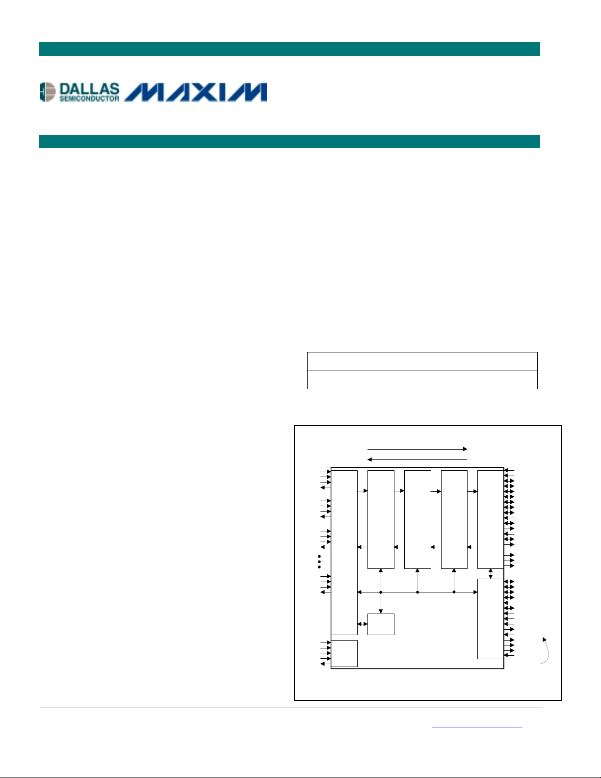
Figure 2-1 shows the major blocks of the device. The DS3131 can be operated in two configurations
depending on whether the local bus is enabled or not (Figure 2-2).
The Layer 1 block handles the physical input and output of serial data to and from the DS3131. The
DS3131 is capable of operating in a number of modes and can be used in many applications requiring
high-density and high-speed HDLC termination. Section 15 details a few common applications for the
DS3131. The Layer 1 block prepares the incoming data for the HDLC block and grooms data from the
HDLC block for transmission. The Layer 1 block interfaces directly to the BERT block. The BERT
block can generate and detect both pseudorandom and repeating bit patterns and is used to test and stress
data communication links. The BERT block is a global chip resource that can be assigned to an y one of
the 40 bit-synchronous ports.
The DS3131 BoSS is composed of 40 bit-synchronous HDLC controllers (one for each port) that are
each capable of operating at speeds up to 52Mbps. The bit-synchronous HDLC controllers also have
serial interfaces. The HDLC controllers perform all of the Layer 2 processing, which includes zero
stuffing and destuffing, flag generation and detection, CRC generation and checking, and abort
generation and checking.
In the receive path, the f ollowing process occurs. The HDLC controllers collect the incoming data and
then signal the FIFO that the controller has data to transfer. The 40 ports are priority decoded (Port 0 gets
the highest priority) for the data transfer from the HDLC controllers to the FIFO block. There is no
priority of transfer between the HDLC controllers and the FIFO because the DS3131 handles up to
132Mbps in both the receive and the transmit directions without any potential data loss because of
priority conflicts.
7 of 174
Page 8

DS3131
The FIFO transfers data from the HDLC engines into the FIFO and checks to see if the FIFO has filled to
beyond the programmable high watermark. If it has, the FIFO signals to the DMA that data is ready to be
burst read from the FIFO to the PCI bus. The FIFO block controls the DMA block and it tells the DMA
when to transfer data from the FIFO to the PCI bus. Since the DS3131 can handle multiple HDLC
channels, it is possible that at any one time, several HDLC channels may need to have data transferred
from the FIFO to the PCI bus. The FIFO determines which HDLC channel the DMA handles next
through a host configurable algorithm, which allows the selection to be either round robin or priority,
decoded (with HDLC channel 1 getting the highest priority). Depending on the application, the selection
of this algorithm can be quite important. The DS3131 cannot control when it is granted PCI bus access
and, if bus access is restricted, then the host may wish to prioritize which HDLC channels get top
priority access to the PCI bus when it is granted to the DS3131.
When the DMA transfers data from the FIFO to the PCI bus, it burst reads all available data in the FIFO
(even if the FIFO contains multiple HDLC packets) and tries to empty the FIFO. If an incoming HDLC
packet is not large enough to fill the FIFO to the high watermark, then the FIFO does not wait for more
data to enter. It signals the DMA that an end-of-frame (EOF) w as detected and that data is ready to be
transferred from the FIFO to the PCI bus.
In the transmit path, a very similar process occurs. As soon as an HDLC channel is enabled, the H DLC
(Layer 2) engines begin requesting data from the FIFO. Like the receive side, the 40 ports are priorit y
decoded with port 0 (HDLC channel #1) getting the highest priority. Therefore, if multiple ports are
requesting packet data, the FIFO first satisfies the requirements on all the enabled HDLC channels in the
lower numbered ports before moving to the higher numbered ports. Again, there is no potential data loss
as long as the transmit throughput maximum of 132Mbps is not exceeded. When the FIFO detects that an
HDLC engine needs data, it then transfers the data from the FIFO to the HDLC engines. If the FIFO
detects it is below the low watermark, it checks with the DMA to see if there is any data available for
that HDLC channel. The DMA knows if any data is available because the host on the PCI bus has
informed it of such through the pending-queue descriptor. When the DM A detects that data is avail able,
it informs the FIFO, which then decides which HDLC channel gets the highest priority to the DMA to
transfer data from the PCI bus into the FIFO. Again, since the DS3131 can handle multiple HDLC
channels, it is possible that at any one time, several HDLC channels may need the DMA to burst data
from the PCI bus into the FIFO. The FIFO determines which HDLC channel the DMA handles next
through a host-configurable algorithm, which allows the selection to be either round robin or priority
decoded (with HDLC channel 1 getting the highest priority).
When the DMA begins burst-writing data into the FIFO, it tries to completely fill the FIFO with HDLC
packet data even if it that means writing multiple packets. Once the FIFO detects that the DMA has filled
it to beyond the low watermark (or an EOF is reached), the FIFO begins transferring data to the HDLC
controller.
One of the DS3131’s unique attributes is the DMA’s structure. The DMA maintains maximum
flexibility, yet reduces the number of bus cycles required to transfer packet data. The DMA uses a
flexible scatter/gather technique, which all ows that packet data to be placed anywhere within the 32-bit
address space. The user has the option on the receive side of two different buffer siz es, which are called
“large” and “small” but that can be set to an y size up to 8191 Bytes. The user can choose to store the
incoming data in the large buffers, in the small buffers, or in the small buffers first, filling the large
buffers as needed. The varying buffer storage options allow the user to make the best use of available
memory and balance the trade-off between latency and bus utilization.
8 of 174
Page 9

DS3131
The DMA uses a set of descriptors to know where to store the incoming H D LC packet data and wh ere to
obtain HDLC packet data ready to be transmitted. The descriptors are fixed-size messages that are
handed back and forth from the DMA to the host. Since this descriptor transfer uses bus cycles, the
DMA has been structured to minimize the number of transfers required. For example, on the receive
side, the DMA obtains descriptors from the host to know where in the 32-bit address space to place the
incoming packet data. These descriptors are known as free-queue descriptors. When the DMA reads
these descriptors off the PCI bus, they provide all the information the DMA needs to store the incoming
data. Unlike other existing scatter/gather DMA arc hitectures, the DS3131 D MA does not need additional
bus cycles to determine where to place the data. Other DMA archite ctures tend to use pointers, which
require them to go back onto the bus to obtain more information and hence use more bus cycles.
Another technique the DMA uses to maximize bus utilization is burst reading and writing the
descriptors. The BoSS can be enabled to read and write the d escriptors in bu rsts of 8 or 1 6 instead o f one
at a time. Since there is fixed overhead associated with each bus transaction, the ability to burst read and
write descriptors allows the device to share the bus overhead among 8 or 16 descriptor transactions,
reducinga the total number of bus cycles needed.
The DMA can also burst up to 256 dwords (1024 Bytes) onto the PCI bus. This helps minimize bus
cycles by allowing the device to burst large amounts of data in a smaller number of bus transactions.
This reduces bus cycles by reducing the amount of fixed overhead placed on the bus.
When the local bus is enabled, ports 28 to 39 (HDLC channels 29 to 40) are disabled to make room for
the signals needed by the local bus. The local bus block has two modes of operation. It can be us ed as a
bridge from the PCI bus, in which case it is a bus master. It can also be used as a confi guration bus, in
which case it is a bus slave. The bridge mode allows the host on the PCI bus to access the local bus. The
DS3131 maps data from the PCI bus to the local bus. In the configuration mode, the local bus is used
only to control and monitor the DS3131, while the HDLC packet data is still transferred to the host
through the PCI bus.
9 of 174
Page 10
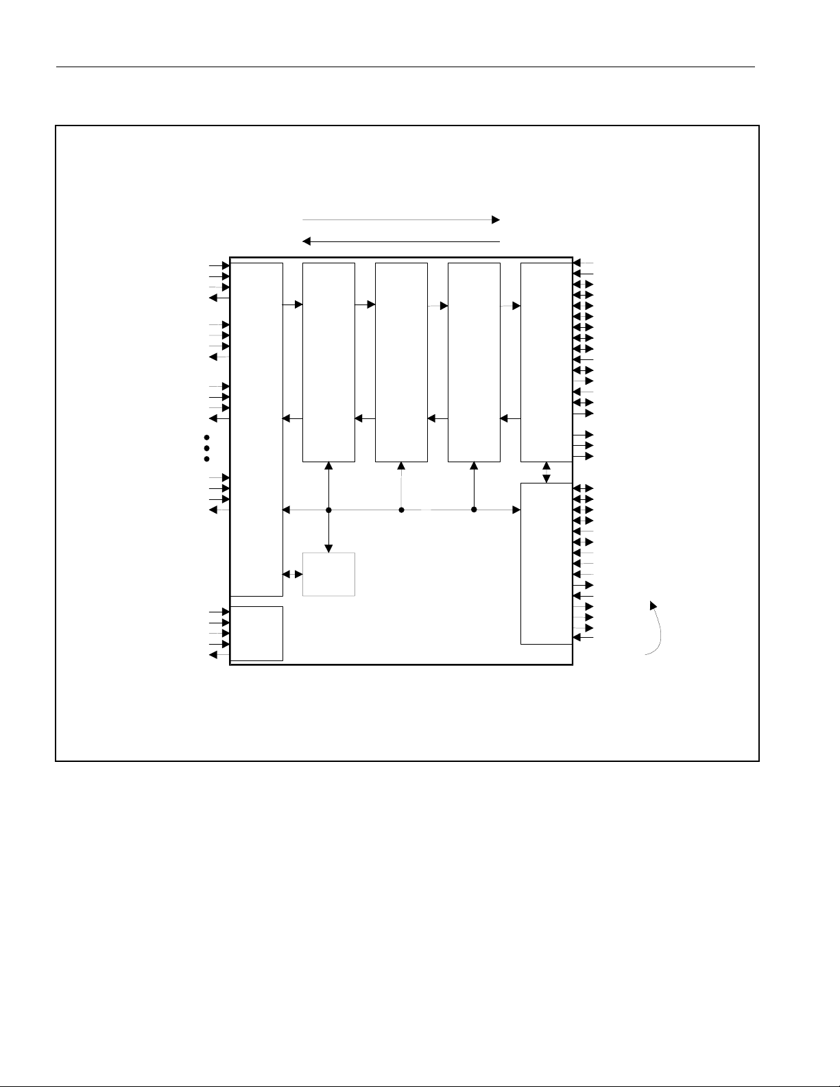
Figure 2-1. Block Diagram
K
PRST
P
P
E
P
Y
P
Y
P
P
P
L
P
L
PREQ
PGNT
P
R
P
R
PXAS
PXDS
P
T
J
T
K
LWR
L
LINT
LRDY
LCS
R
G)L
K
K
A
LBHE
K
DS3131
RECEIVE DIRECTION
TRANSMIT DIRECTION
RC0
RD0
RC1
RD1
RC2
RD2
RC39
RD39
TC39
TD39
TRS
JTDI
JTMS
JTCL
JTDO
TC0
TD0
TC1
TD1
TC2
TD2
LAYER 1 BLOCK (SECT. 6)
JTAG
TEST
ACCESS
(SECT. 12)
CONTROLLERS (SECT. 7)
40-BIT SYNCHRONOUS HDLC
BERT
(SECT. 6)
FIFO BLOCK (SECT. 8)
DMA BLOCK (SECT. 9)
INTERNAL CONTROL BUS
DS3131
PCI BLOCK (SECT. 10)
(SECT. 11)
LOCAL BUS BLOC
PIN NAMES IN ( )
THE DEVICE IS IN
THE MOT MODE
(i.e., LIM = 1).
PCL
PAD[31:0]
CBE[3:0]
PPAR
FRAM
IRD
TRD
STO
IDSE
DEVSE
PER
SER
XBLAS
LA[19:0]
LD[15:0]
(LR/W)
RD(LDS)
LIM
LMS
LHOLD(LB
LHLDA(LB
LCL
LBPXS
)
BGAC
RE ACTIVE WHEN
10 of 174
Page 11
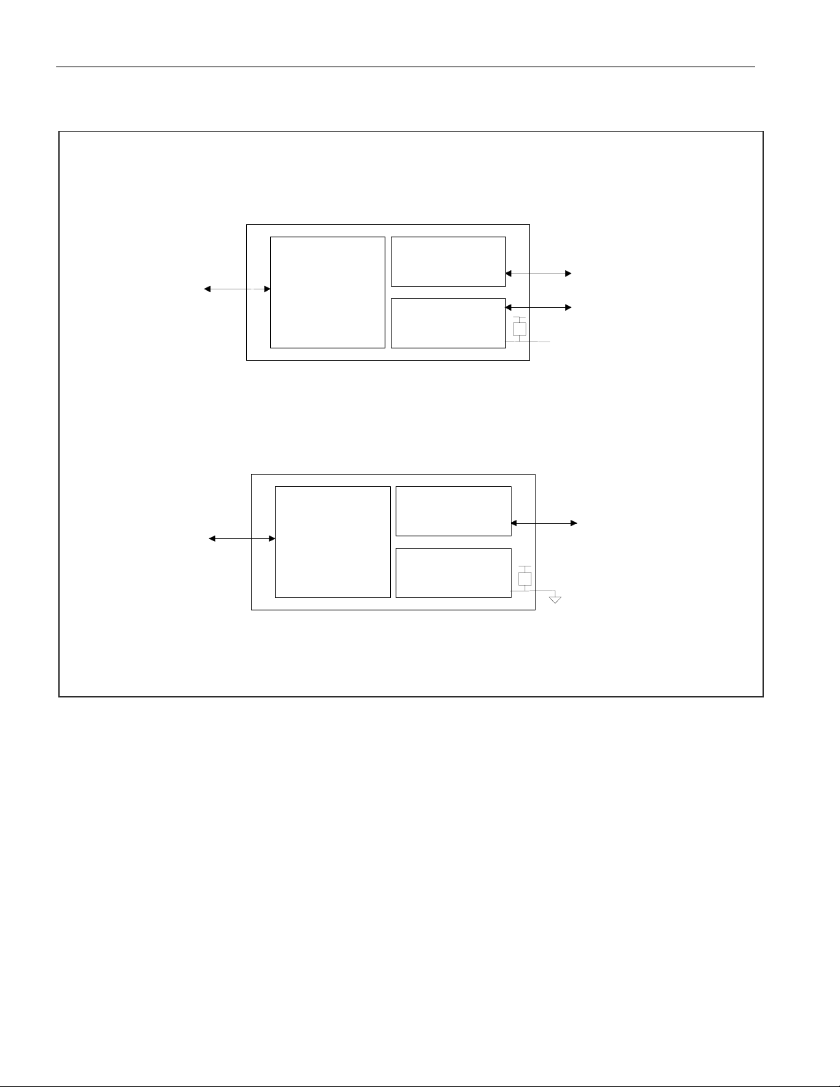
Figure 2-2. Configuration Options
28 Bit-Synchronous Ports/Local Bus Enabled (Default State)
DS3131
28 Serial
Interfaces
(Ports 0 to 27)
40 Serial
Interfaces
(Ports 0 to 39)
PCI Bus
28
Bit-Synchronous
HDLC Controllers
Local Bus
LBPXS
PU
Open-Circuited
40 Bit-Synchronous Ports/Local Bus Disabled
PCI Bus
40
Bit-Synchronous
HDLC Controllers
Local Bus
LBPXS
PU
11 of 174
Page 12

DS3131
Restrictions
In creating the overall system architecture, the user must balance the port, throughput, and HDLC
channel restrictions of the DS3131. Table 2-A lists all of the upper-bound maximum restrictions.
Table 2-A. Restrictions
ITEM RESTRICTION
Port
Throughput
HDLC
Maximum of 40 physical ports
Maximum data rate of 52Mbps
Maximum receive: 132Mbps (Refer to Application Note 358: DS3134
PCI Bus Utilization.)
Maximum transmit: 132Mbps
Maximum of 40 channels
Internal Device Configuration Registers
All internal device configuration registers (with the exception of the PCI configuration registers, which
are 32-bit registers) are 16 bits wide and are not byte addressable. When the host on the PCI bus accesses
these registers, the particular combination of byte enables (i.e., PCBE signals) is not important, but at
least one of the byte enables must be asserted for a transaction to occur. All registers are read/write,
unless otherwise noted. Reserved bits should not be modified to allow for future upgrades to the d evice.
These bits should be treated as having no meaning and could be either 0 or 1 when read.
Initialization
On a system reset (which can be invoked b y either hardware a ction through the PRST signal or software
action through the RST control bit in the master reset and ID register), all of the internal device
configuration registers are set to 0 (0000h). The local bus bridge mode control register (LBBMC) is not
affected by a software-invoked system reset; it is forced to all zeros only by a hardware reset. The
internal registers that are access ed indirectl y (these are listed as “indirect r egisters” in the data sheet and
consist of the port DS0 configuration registers in the Layer 1 block, the DMA configuration RAMs, and
the FIFO registers) are not affe cted by a system reset, so they must be configured on power-up by the
host to a proper state.
By design, the DS3131 BoSS does not take control of the PCI bus upon power-up. All physical ports
start up by sending all ones (not the HDLC idle code), so the BoSS is idle upon power-up. Please note,
however, that the BoSS uses internal RAM to periodically store and retrieve the states of the internal
state machines. Because there are many such complex state machi nes and in terworkin g fun cti onal b l ocks
inside the BoSS, all internal registers must be initialized to a known state before any data packets can be
transmitted and received.
Table 2-B lists the steps required to initialize the DS3131. It is imperative that they are followed exactl y
in the order presented, or exactly as implemented in Dallas Semiconductor DS3131 driver code.
12 of 174
Page 13

DS3131
Table 2-B. Initialization Steps
INITIALIZATION STEP COMMENTS
1) System Reset System reset can be invoked by either hardware action
through the PRST signal (recommended) or software
action through the RST control bit in the master reset and
ID register. All configuration registers are set to 0 (0000h)
by system reset.
2) Configure LBBMC Register Please note that this register is not affected by the
software-invoked system reset. It is forced to all zeros only
by the hardware reset.
3) Configure PCI This is achieved by asserting the PIDSEL signal.
4) Disable Transmit and Receive DMA for each
Channel
Ensure the DMA is off on both the transmit and receive
sides through the channel-enable bit in the transmit and
receive RAM.
5) Configure Receive DMA Program the receive DMA configuration RAM.
6) Configure Receive FIFO Program the receive FIFO registers.
7) Configure Receive Layer 1 Program the receive port registers (RP[n]CR).
8) Configure Transmit DMA Program the transmit DMA configuration RAM.
9) Configure Transmit FIFO Program the transmit FIFO registers.
10) Configure Transmit Layer 2 Program the transmit HDLC port control registers
(TH[n]CR).
11) Configure Transmit Layer 1 Program the transmit port registers (TP[n]CR).
12) Configure Receive Layer 2 Program the receive HDLC port control registers
(RH[n]CR).
13) Enable Receive DMA for Each Channel Set the channel-enable bit in the receive DMA
configuration RAM for the channels in use.
14) Enable Transmit DMA for Each Channel Set the channel-enable bit in the transmit DMA
configuration RAM for the channels in use.
15) Configure Interrupts Optional,
16) Configure Master Control Register Set the RDE and TDE control bits in the master
configuration (MC) register .
Table 2-C. Indirect Registers
REGISTER NAME NUMBER OF INDIRECT REGISTERS
Receive DMA Configuration RDMAC 120 (three for each HDLC Channel)1
Transmit DMA Configuration TDMAC 240 (six for each HDLC Channel)1
Receive FIFO Starting Block Pointer RFSBP 40 (one for each HDLC Channel)
Receive FIFO Block Pointer RFBP 512 (one for each FIFO Block)
Receive FIFO High Watermark RFHWM 40 (one for each HDLC Channel)
Transmit FIFO Starting Block Pointer TFSBP 40 (one for each HDLC Channel)
Transmit FIFO Block Pointer TFBP 512 (one for each FIFO Block)
Transmit FIFO Low Watermark TFLWM 40 (one for each HDLC Channel)
1
On device initialization, the host needs only to write to one of the receive and one of the transmit DMA registers. See Sections 9.2.5 and 9.3.5
for details.
13 of 174
Page 14
DS3131
3. SIGNAL DESCRIPTION
3.1 Overview/Signal List
This section describes the input and output signals on the DS3131. Signal names follow a convention
that is shown in the Signal Naming Convention table below. Table 3-A
lists all of the signals, their signal
type, description, and pin location.
Signal Naming Convention
FIRST LETTER SIGNAL CATEGORY SECTION
R Receive Serial Port 3.2
T Transmit Serial Port 3.2
L Local Bus 3.3
J JTAG Test Port 3.4
LXXX–T/RXXX: Multiplexed local bus with extended ports controlled by LBPXS.
P PCI Bus 3.5
Table 3-A. Signal Description
PIN NAME TYPE FUNCTION
W20 TC0 I Transmit Serial Clock for Port 0
U19 TC1 I Transmit Serial Clock for Port 1
T17 TC2 I Transmit Serial Clock for Port 2
U20 TC3 I Transmit Serial Clock for Port 3
T19 TC4 I Transmit Serial Clock for Port 4
R18 TC5 I Transmit Serial Clock for Port 5
R19 TC6 I Transmit Serial Clock for Port 6
P18 TC7 I Transmit Serial Clock for Port 7
P20 TC8 I Transmit Serial Clock for Port 8
N19 TC9 I Transmit Serial Clock for Port 9
M17 TC10 I Transmit Serial Clock for Port 10
M19 TC11 I Transmit Serial Clock for Port 11
L19 TC12 I Transmit Serial Clock for Port 12
L20 TC13 I Transmit Serial Clock for Port 13
K19 TC14 I Transmit Serial Clock for Port 14
J20 TC15 I Transmit Serial Clock for Port 15
J18 TC16 I Transmit Serial Clock for Port 16
H19 TC17 I Transmit Serial Clock for Port 17
G20 TC18 I Transmit Serial Clock for Port 18
F20 TC19 I Transmit Serial Clock for Port 19
F19 TC20 I Transmit Serial Clock for Port 20
G17 TC21 I Transmit Serial Clock for Port 21
E19 TC22 I Transmit Serial Clock for Port 22
E18 TC23 I Transmit Serial Clock for Port 23
C20 TC24 I Transmit Serial Clock for Port 24
D18 TC25 I Transmit Serial Clock for Port 25
B20 TC26 I T ransmit Serial Clock for Port 26
B19 TC27 I T ransmit Serial Clock for Port 27
V19 TD0 O Transmit Serial Data for Port 0
U18 TD1 O Transmit Serial Data for Port 1
V20 TD2 O Transmit Serial Data for Port 2
14 of 174
Page 15

PIN NAME TYPE FUNCTION
T18 TD3 O Transmit Serial Data for Port 3
T20 TD4 O Transmit Serial Data for Port 4
P17 TD5 O Transmit Serial Data for Port 5
R20 TD6 O Transmit Serial Data for Port 6
P19 TD7 O Transmit Serial Data for Port 7
N18 TD8 O Transmit Serial Data for Port 8
N20 TD9 O Transmit Serial Data for Port 9
M18 TD10 O Transmit Serial Data for Port 10
M20 TD11 O Transmit Serial Data for Port 11
L18 TD12 O Transmit Serial Data for Port 12
K20 TD13 O Transmit Serial Data for Port 13
K18 TD14 O Transmit Serial Data for Port 14
J19 TD15 O Transmit Serial Data for Port 15
H20 TD16 O Transmit Serial Data for Port 16
H18 TD17 O Transmit Serial Data for Port 17
G19 TD18 O Transmit Serial Data for Port 18
G18 TD19 O Transmit Serial Data for Port 19
E20 TD20 O Transmit Serial Data for Port 20
F18 TD21 O Transmit Serial Data for Port 21
D20 TD22 O Transmit Serial Data for Port 22
D19 TD23 O Transmit Serial Data for Port 23
E17 TD24 O Transmit Serial Data for Port 24
C19 TD25 O Transmit Serial Data for Port 25
C18 TD26 O Transmit Serial Data for Port 26
A20 TD27 O Transmit Serial Data for Port 27
W9, U14, C10 N.C. — No Connect. Do not connect any signal to this pin.
V17 PAD0 I/O PCI Multiplexed Address and Data Bit 0
U16 PAD1 I/O PCI Multiplexed Address and Data Bit 1
Y18 PAD2 I/O PCI Multiplexed Address and Data Bit 2
W17 PAD3 I/O PCI Multiplexed Address and Data Bit 3
V16 PAD4 I/O PCI Multiplexed Address and Data Bit 4
Y17 PAD5 I/O PCI Multiplexed Address and Data Bit 5
W16 PAD6 I/O PCI Multiplexed Address and Data Bit 6
V15 PAD7 I/O PCI Multiplexed Address and Data Bit 7
W15 PAD8 I/O PCI Multiplexed Address and Data Bit 8
V14 PAD9 I/O PCI Multiplexed Address and Data Bit 9
Y15 P AD10 I/O PCI Multiplexed Address and Data Bit 10
W14 PAD11 I/O PCI Multiplexed Address and Data Bit 11
Y14 P AD12 I/O PCI Multiplexed Address and Data Bit 12
V13 P AD13 I/O PCI Multiplexed Address and Data Bit 13
W13 PAD14 I/O PCI Multiplexed Address and Data Bit 14
Y13 P AD15 I/O PCI Multiplexed Address and Data Bit 15
V9 PAD16 I/O PCI Multiplexed Address and Data Bit 16
U9 PAD17 I/O PCI Multiplexed Address and Data Bit 17
Y8 PAD18 I/O PCI Multiplexed Address and Data Bit 18
W8 PAD19 I/O PCI Multiplexed Address and Data Bit 19
V8 PAD20 I/O PCI Multiplexed Address and Data Bit 20
Y7 PAD21 I/O PCI Multiplexed Address and Data Bit 21
W7 PAD22 I/O PCI Multiplexed Address and Data Bit 22
V7 PAD23 I/O PCI Multiplexed Address and Data Bit 23
U7 PAD24 I/O PCI Multiplexed Address and Data Bit 24
V6 PAD25 I/O PCI Multiplexed Address and Data Bit 25
DS3131
15 of 174
Page 16

PIN NAME TYPE FUNCTION
Y5 PAD26 I/O PCI Multiplexed Address and Data Bit 26
W5 PAD27 I/O PCI Multiplexed Address and Data Bit 27
V5 PAD28 I/O PCI Multiplexed Address and Data Bit 28
Y4 PAD29 I/O PCI Multiplexed Address and Data Bit 29
Y3 PAD30 I/O PCI Multiplexed Address and Data Bit 30
U5 PAD31 I/O PCI Multiplexed Address and Data Bit 31
Y16
V12
Y9
W6
PCBE0
PCBE1
PCBE2
PCBE3
I/O
I/O
I/O
I/O
PCI Bus Command/Byte Enable Bit 0
PCI Bus Command/Byte Enable Bit 1
PCI Bus Command/Byte Enable Bit 2
PCI Bus Command/Byte Enable Bit 3
Y2 PCLK I PCI and System Clock. A 33MHz clock is applied here.
Y11
W10
W4
PDEVSEL
PFRAME
PGNT
I/O
I/O
I
PCI Device Select
PCI Cycle Frame
PCI Bus Grant
Y6 PIDSEL I P CI Initialization Device Sele ct
W18
V10
PINT
PIRDY
O
I/O
PCI Interrupt
PCI Initiator Ready
W12 PPAR I/O PCI Bus Parity
V11
V4
W3
Y12
W11
Y10
V18
Y20
W19
PPERR
PREQ
PRST
PSERR
PSTOP
PTRDY
PXAS
PXBLAST
PXDS
I/O
O
I
O
I/O
I/O
O
O
O
PCI Parity Error
PCI Bus Request
PCI Reset
PCI System Error
PCI Stop
PCI Target Ready
PCI Extension Signal: Address Strobe
PCI Extension Signal: Burst Last
PCI Extension Signal: Data Strobe
Y1 RC0 I Receive Serial Clock for Port 0
V3 RC1 I Receive Serial Clock for Port 1
V2 RC2 I Receive Serial Clock for Port 2
T4 RC3 I Receive Serial Clock for Port 3
U2 RC4 I Receive Serial Clock for Port 4
U1 RC5 I Receive Serial Clock for Port 5
R3 RC6 I Receive Serial Clock for Port 6
T1 RC7 I Receive Serial Clock for Port 7
P3 RC8 I Receive Serial Clock for Port 8
P2 RC9 I Receive Serial Clock for Port 9
N3 RC10 I Receive Serial Clock for Port 10
N1 RC11 I Receive Serial Clock for Port 11
M2 RC12 I Receive Serial Clock for Port 12
L3 RC13 I Receive Serial Clock for Port 13
L1 RC14 I Receive Serial Clock for Port 14
K3 RC15 I Receive Serial Clock for Port 15
J1 RC16 I Receive Serial Clock for Port 16
J3 RC17 I Receive Serial Clock for Port 17
H1 RC18 I Receive Serial Clock for Port 18
H3 RC19 I Receive Serial Clock for Port 19
G2 RC20 I Receive Serial Clock for Port 20
F1 RC21 I Receive Serial Clock for Port 21
G4 RC22 I Receive Serial Clock for Port 22
E1 RC23 I Receive Serial Clock for Port 23
E3 RC24 I Receive Serial Clock for Port 24
16 of 174
DS3131
Page 17

PIN NAME TYPE FUNCTION
C1 RC25 I Receive Serial Clock for Port 25
D3 RC26 I Receive Serial Clock for Port 26
C2 RC27 I Receive Serial Clock for Port 27
W2 RD0 I Receive Serial Data for Port 0
W1 RD1 I Receive Serial Data for Port 1
U3 RD2 I Receive Serial Data for Port 2
V1 RD3 I Receive Serial Data for Port 3
T3 RD4 I Receive Serial Data for Port 4
T2 RD5 I Receive Serial Data for Port 5
P4 RD6 I Receive Serial Data for Port 6
R2 RD7 I Receive Serial Data for Port 7
R1 RD8 I Receive Serial Data for Port 8
P1 RD9 I Receive Serial Data for Port 9
N2 RD10 I Receive Serial Data for Port 10
M3 RD11 I Receive Serial Data for Port 11
M1 RD12 I Receive Serial Data for Port 12
L2 RD13 I Receive Serial Data for Port 13
K1 RD14 I Receive Serial Data for Port 14
K2 RD15 I Receive Serial Data for Port 15
J2 RD16 I Receive Serial Data for Port 16
J4 RD17 I Receive Serial Data for Port 17
H2 RD18 I Receive Serial Data for Port 18
G1 RD19 I Receive Serial Data for Port 19
G3 RD20 I Receive Serial Data for Port 20
F2 RD21 I Receive Serial Data for Port 21
F3 RD22 I Receive Serial Data for Port 22
E2 RD23 I Receive Serial Data for Port 23
D1 RD24 I Receive Serial Data for Port 24
E4 RD25 I Receive Serial Data for Port 25
D2 RD26 I Receive Serial Data for Port 26
B1 RD27 I Receive Serial Data for Port 27
A19 JTMS I JTAG IEEE 1149.1 Test Mode Select
D16 JTDO O JTAG IEEE 1149.1 Test Serial-Data Output
B18 JTCLK I JTAG IEEE 1149.1 Test Serial Clock
B17 JTRST I JTAG IEEE 1149.1 Test Reset
C17 JTDI I JTAG IEEE 1149.1 Test Serial-Data Input
C8 LA0–RD37 I/O–I Local Bus Address Bit 0–Receive Serial Data for Port 37
A7 LA1–RC37 I/O–I Local Bus Address Bit 1–Receive Serial Clock for Port 37
B7 LA2–RD36 I/O–I Local Bus Address Bit 2–Receive Serial Data for Port 36
A6 LA3–RC36 I/O–I Local Bus Address Bit 3–Receive Serial Clock for Port 36
C7 LA4–RD35 I/O–I Local Bus Address Bit 4–Receive Serial Data for Port 35
B6 LA5–RC35 I/O–I Local Bus Address Bit 5–Receive Serial Clock for Port 35
A5 LA6–RD34 I/O–I Local Bus Address Bit 6–Receive Serial Data for Port 34
D7 LA7–RC34 I/O–I Local Bus Address Bit 7–Receive Serial Clock for Port 34
C6 LA8–RD33 I/O–I Local Bus Address Bit 8–Receive Serial Data for Port 33
B5 LA9–RC33 I/O–I Local Bus Address Bit 9–Receive Serial Clock for Port 33
A4 LA10–RD32 I/O–I Local Bus Address Bit 10–Receive Serial Data for Port 32
C5 LA11–RC32 I/O–I Local Bus Address Bit 11–Receive Serial Clock for Port 32
B4 LA12–RD31 I/O–I Local Bus Address Bit 12–Receive Serial Data for Port 31
A3 LA13–RC31 I/O–I Local Bus Address Bit 13–Receive Serial Clock for Port 31
D5 LA14–RD30 I/O–I Local Bus Address Bit 14–Receive Serial Data for Port 30
C4 LA15–RC30 I/O–I Local Bus Address Bit 15–Receive Serial Clock for Port 30
DS3131
17 of 174
Page 18

PIN NAME TYPE FUNCTION
B3 LA16–RD29 I/O–I Local Bus Address Bit 16–Receive Serial Data for Port 29
B2 LA17–RC29 I/O–I Local Bus Address Bit 17–Receive Serial Clock for Port 29
A2 LA18–RD28 I/O–I Local Bus Address Bit 18–Receive Serial Data for Port 28
C3 LA19–RC28 I/O–I Local Bus Address Bit 19–Receive Serial Clock for Port 28
A18 LD0–TC28 I/O–I Local Bus Data Bit 0–Transmit Serial Clock for Port 28
A17 LD1–TD28 I/O–O Local Bus Data Bit 1–Transmit Serial Data for Port 28
C16 LD2–TC29 I/O–I Local bus Data Bit 2–Transmit Serial Clock for Port 29
B16 LD3–TD29 I/O–O Local Bus Data Bit 3–Transmit Serial Data for Port 29
A16 LD4–TC30 I/O–I Local Bus Data Bit 4–Transmit Serial Clock for Port 30
C15 LD5–TD30 I/O–O Local Bus Data Bit 5–Transmit Serial Data for Port 30
D14 LD6–TC31 I/O–I Local Bus Data Bit 6–Transmit Serial Clock for Port 31
B15 LD7–TD31 I/O–O Local Bus Data Bit 7–Transmit Serial Data for Port 31
A15 LD8–TC32 I/O–I Local Bus Data Bit 8–Transmit Serial Clock for Port 32
C14 LD9–TD32 I/O–O Local Bus Data Bit 9–Transmit Serial Data for Port 32
B14 LD10–TC33 I/O–I Local Bus Data Bit 10–Transmit Serial Clock for Port 33
A14 LD11–TD33 I/O–O Local Bus Data Bit 11–Transmit Serial Data for Port 33
C13 LD12–TC34 I/O–I Local Bus Data Bit 12–Transmit Serial Clock for Port 34
B13 LD13–TD34 I/O–O Local Bus Data Bit 13–Transmit Serial Data for Port 34
A13 LD14–TC35 I/O–I Local Bus Data Bit 14-Transmit Serial Clock for Port 35
D12 LD15–TD35 I/O–O Local Bus Data Bit 15–Transmit Serial Data for Port 35
C9 LMS–RD39 I–I Local Bus Mode Select–Receive Serial Data for Port 39
B11 LBHE–TD37 O–O Local Bus Byte High Enable–Transmit Serial Data for Port 37
B10 LHOLD–TD39 O–O Local Bus Hold (Local Bus Request)–Transmit Serial Data for Port 39
A9 LWR–RC39 I/O–I
C12 LIM–TC36 I–I Local Bus Intel/Motorola Bus Select–Transmit Serial Clock for Port 36
C11 LHLDA–TC38 I–I
B12 LCLK–TD36 O–O Local Bus Clock–Transmit Serial Data for Port 36
A11 LBGACK–TD38 O–O Local Buses Grant Acknowledge–Transmit Serial Data for Port 38
A8 LRD–RD38 I/O–I
A12 LINT–TC37 I/O–I Local Bus Interrupt–Transmit Serial Clock for Port 37
A10 LRDY–TC39 I–I Local Bus PCI Bridge Ready–Transmit Serial Clock for Port 39
B9 LBPXS I Local Bus Port Extension Select. Leave open to enable local bus.
B8 LCS–RC38 I–I Local Bus Chip Select–Receive Serial Data for Port 38
Y19 TEST I Test. Factory test signals; leave open-circuited.
D6, D10, D11,
D15, F4, F17,
K4, K17, L4,
L17, R4, R17,
U6, U10, U11,
U15
A1, D4, D8, D9,
D13, D17, H4,
H17, J17, M4,
N4, N17, U4,
U8, U12, U13,
U17
J9–J12, K9–
K12, L9–L12,
M1, M9–11
VDD — Positive Suppl y, 3.3V (± 10%)
VSS — Ground
VSST — Ground and Thermal Dissipation Ball
Local Bus Write Enable (Local Bus Read/Write Select)–Receive Serial
Clock for Port 39
Local Bus Hold Acknowledge (Local Bus Grant)–Transmit Serial
Clock for Port 38
Local Bus Read Enable (Local Bus Data Strobe)–Receive Serial Data
for Port 38
DS3131
18 of 174
Page 19
Figure 3-1. Signal Floorplan
1234567891011121314151617181920
Y RC0 PCLK PAD30 PAD29 PAD26 PIDSEL PAD21 PAD18 PCBE2* PTRDY*
W RD1 RD0 PRST* PGNT* PAD27 PCBE3* PAD22 PAD19 NC
V RD3 RC2 RC1 PREQ* PAD28 PAD25 PAD23 PAD20 PAD16 PIRDY* PPERR* PCBE1* PAD13 PAD9 PAD7 PAD4 PAD0 PXAS* TD0 TD2 V
U RC5 RC4 RD2 VSS PAD31 VDD PAD24 VSS PAD17 VDD VDD VSS VSS NC VDD PAD1 VSS TD1 TC1 TC3 U
R RD8 RD7 RC6 VDD VDD TC5 TC6 TD6 R
T RC7 RD5 RD4 RC3 TC2 TD3 TC4 TD4 T
P RD9 RC9 RC8 RD6 TD5 TC7 TD7 TC8 P
N RC11 RD10 RC10 VSS VSS TD8 TC9 TD9 N
M RD12 RC12 RD11 VSS VSST VSST VSST VSST TC10 TD10 TC11 TD11 M
L RC14 RD13 RC13 VDD VSST VSST VSST VSST VDD TD12 TC12 TC13 L
K RD14 RD15 RC15 VDD VSST VSST VSST VSST VDD TD14 TC14 TD13 K
PDEV-
PSERR* PAD15 PAD12 PAD10 PCBE0* PAD5 PAD2 TEST
SEL*
P-
PSTOP* PPAR PAD14 PAD11 PAD8 PAD6 PAD3 PINT* PXDS* TC0 W
FRAME*
PXB-
LAST*
DS3131
Y
J RC16 RD16 RC17 RD17 VSST VSST VSST VSST VSS TC16 TD15 TC15 J
H RC18 RD18 RC19 VSS VSS TD17 TC17 TD16 H
G RD19 RC20 RD20 RC22 TC21 TD19 TD18 TC18 G
F RC21 RD21 RD22 VDD VDD TD21 TC20 TC19 F
E RC23 RD23 RC24 RD25 TD24 TC23 TC22 TD20 E
D RD24 RD26 RC26 VSS
LA17-
RC29
LA18RD28
LA19-
RC28
LA16RD29
LA13-
RC31
C RC25 RC27
BRD27
A VSS
1234567891011121314151617181920
LA14-
VDD LA7-RC34 VSS VSS VDD VDD
RD30
LA15-
LA11-
RC30
LA12-
RD31
LA10-
RD32
LA8-RD33 LA4-RD35 LA0-RD37 LMS-RD39 NC
RC32
LA9-RC33 LA5-RC35 LA2-RD36 LCS-RC38 LBPXS
LA6-RD34 LA3-RC36 LA1-RC37 LRD-RD38
LWRRC39
LHOLD-
TD39
LRDY-
TC39
LHLDA-
TC38
LBHE-
TD37
LBGAC-
TD38
LD15-
VSS LD6-TC31 VDD JTDO VSS TC25 TD23 TD22 D
TD35
LD12-
LIM-TC36
LCLK-
TD36
LINT-
TC37
LD9-TD32 LD5-TD30 LD2-TC29 JTDI TD26 TD25 TC24 C
TC34
LD13-
LD10-
TD34
LD14TC35
LD7-TD31 LD3-TD29 JTRST JTCLK TC27 TC26 B
TC33
LD11-
LD8-TC32 LD4-TC30 LD1-TD28 LD0-TC28 JTMS TD27 A
TD33
Receive Ports 0-13 Transmi t Port s 0-13 PCI other VDD
Receive Ports 14-27 Transmit Ports 14-27 JTAG, TEST, and NC VSS
Local B us and P orts 28-39 PCI address and data
19 of 174
Page 20

DS3131
3.2 Serial Port Interface Signal Description
Signal Name: RC0 to RC39
Signal Description: Receive Serial Clock
Signal Type: Input
Data can be clocked into the device either on rising edges (normal clock mode) or falling edges (inverted clock
mode) of RC. This is programmable on a per port basis. RC can operate at speeds from DC to 52MHz. Clock
gapping is acceptable. If not used, this signal should be wired low.
Signal Name: RD0 to RD39
Signal Description: Receive Serial Data
Signal Type: Input
Can be sampled either on the rising edge of RC (normal clock mode) or the falling edge of RC (inverted clock
mode). If not used, this signal should be wired low.
Signal Name: TC0 to TC39
Signal Description: Transmit Serial Clock
Signal Type: Input
Data is clocked out of the device at TD either on rising edges (normal clock mode) or falling edges (inverted clock
mode) of TC. This is programmable on a per port basis. TC can operate at speeds from DC to 52MHz. Clock
gapping is acceptable. If not used, this signal should be wired low.
Signal Name: TD0 to TD39
Signal Description: Transmit Serial Data
Signal Type: Output
Can be updated either on the rising edge of TC (normal clock mode) or the falling edge of TC (inverted clock
mode). TD can be forced either high or low by the TP[n]CR register. See Section 6.1
for details.
3.3 Local Bus Signal Description
Note: The signals listed in this section are only active when the local bus is enabled.
Signal Name: LMS
Signal Description: Local Bus Mode Select
Signal Type: Input
This signal should be connected low when the device operates with no local bus access or if the local bus is used
as a bridge from the PCI bus. This signal should be connected high if the local bus is to be used by an external host
to configure the device.
0 = local bus is in the PCI bridge mode (master)
1 = local bus is in the configuration mode (slave)
Signal Name: LIM
Signal Description: Local Bus Intel/Motorola Bus Select
Signal Type: Input
The signal determines whether the local bus operates in the Intel mode (LIM = 0) or the Motorola mode (LIM =
1). The signal names in parenthesis are operational when the device is in the Motorola mode.
0 = local bus is in the Intel mode
1 = local bus is in the Motorola mode
20 of 174
Page 21

DS3131
Signal Name: LBPXS
Signal Description: Local Bus or Port Extension Select
Signal Type: Input (with internal 10kΩ pullup)
This signal must be left open-circuited (or connected high) to activate and enable the local bus. When this signal is
connected low, the local bus is disabled and its signals are redefined to support 12 bit-synchronous HDLC
controllers on ports 28 to 39 (Table 3-A
).
0 = local bus disabled
1 (or open -ircuited) = local bus enabled
Signal Name: LD0 to LD15
Signal Description: Local Bus Nonmultiplexed Data Bus
Signal Type: Input/Output (three-state capable)
In PCI bridge mode (LMS = 0), data from/to the PCI bus can be transferred to/from these signals. When writing
data to the local bus, these signals are outputs and updated on the rising edge of LCLK. When reading data from
the local bus, these signals are inputs, which are sampled on the rising edge of LCLK. Depending on the assertion
of the PCI byte enables (PCBE0 to PCBE3) and the local bus-width (LBW) control bit in the local bus bridge
mode control register (LBBMC), this data bus uses all 16 bits (LD[ 15:0]) or just the lower 8 bits (LD[7:0]) or the
upper 8 bits (LD[15:8]). If the upper LD bits (LD[15:8]) are used, then the local bus high-enable signal (LBHE) is
asserted during the bus transaction. If the local bus is not currently involved in a bus transaction, all 16 signals are
three-stated. When reading data from the local bus, these signals are outputs that are updated on the rising edge of
LCLK. When writing data to the local bus, these signals become inputs, which are sampled on the rising edge of
LCLK. In configuration mode (LMS = 1), the external host configures the device and obtains real-time status
information about the device through these signals. Only the 16-bit bus width is allowed (i.e., byte addressing is
not available).
Signal Name: LA0 to LA19
Signal Description: Local Bus Nonmultiplexed Address Bus
Signal Type: Input/Output (three-state capable)
In the PCI bridge mode (LMS = 0), these signals are outputs that are asserted on the rising edge of LCLK to
indicate which address is written to or read from. If bus arbitration is enabled through the local bus arbitration
(LARBE) control bit in the LBBMC register, these signals are three-stated when the local bus is not currently
involved in a bus transaction and driven when a bus transaction is active. When bus arbitration is disabled, these
signals are always driven. These signals are sampled on the rising edge of LCLK to determine the internal device
configuration register that the external host wishes to access. In configuration mode (LMS = 1), these signals are
inputs and only the bottom 16 bits (LA[15:0]) are active; the upper four (LA[19:16]) are ignored and should be
connected low.
Signal Name: LWR
LWR (LR/WWWW)
LWRLWR
Signal Description: Local Bus Write Enable (Local Bus Read/Write Select)
Signal Type: Input/Output (three-state capable)
In the PCI bridge mode (LMS = 0), this output signal is asserted on the rising edge of LCLK. In Intel mode
(LIM = 0), it is asserted when data is to be written to the local bus. In Motorola mode (LIM = 1), this signal
determines whether a read or write is to occur. If bus arbitration is enabled through the LARBE control bit in the
LBBMC register, this signal is three-stated when the local bus is not currently involved in a bus transaction and
driven when a bus transaction is active. When bus arbitration is disabled, this signal is always driven. In
configuration mode (LMS = 1), this signal is sampled on the rising edge of LCLK. In Intel mode (LIM = 0), it
determines when data is to be written to the device. In Motorola mode (LIM = 1), this signal determines whether a
read or write is to occur.
21 of 174
Page 22

DS3131
Signal Name: LRD
LRD (LDS
LDS)
LRDLRD
LDSLDS
Signal Description: Local Bus Read Enable (Local Bus Data Strobe)
Signal Type: Input/Output (three-state capable)
In the PCI bridge mode (LMS = 0), this active-low output signal is asserted on the rising edge of LCLK. In Intel
mode (LIM = 0), it is asserted when data is to be read from the local bus. In Motorola mode (LIM = 1), the rising
edge is used to write data into the slave device. If bus arbitration is enabled through the LARBE control bit in the
LBBMC register, this signal is three-stated when the local bus is not currently involved in a bus transaction and
driven when a bus transaction is active. When bus arbitration is disabled, this signal is always driven. In
configuration mode (LMS = 1), this signal is an active-low input that is sampled on the rising edge of LCLK. In
Intel mode (LIM = 0), it determines when data is to be read from the device. In Motorola mode (LIM = 1), the
rising edge writes data into the device.
Signal Name: LINT
LINT
LINTLINT
Signal Description: Local Bus Interrupt
Signal Type: Input/Output (open drain)
In the PCI bridge mode (LMS = 0), this active-low signal is an input that is sampled on the rising edge of LCLK.
If asserted and unmasked, this signal causes an interrupt at the PCI bus through the PINTA signal. If not used in
PCI bridge mode, this signal should be connected high. In configuration mode (LMS = 1), this signal is an opendrain output that is forced low if one or more unmasked interrupt sources within the device is active. The signal
remains low until either the interrupt is serviced or masked.
Signal Name: LRDY
LRDY
LRDYLRDY
Signal Description: Local Bus PCI Bridge Ready (PCI Bridge Mode Only)
Signal Type: Input
This active-low signal is sampled on the rising edge of LCLK to determine when a bus transaction is complete.
This signal is only examined when a bus transaction is taking place. This signal is ignored when the local bus is in
configuration mode (LMS = 1) and should be connected high.
Signal Name: LHLDA (LBG
LBG)
LBGLBG
Signal Description: Local Bus Hold Acknowledge (Local Bus Grant) (PCI Bridge Mode Only)
Signal Type: Input
This input signal is sampled on the rising edge of LCLK to determine when the device has been granted access to
the bus. In Intel mode (LIM = 0), this is an active-high signal; in Motorola mode (LIM = 1) this is an active-low
signal. This signal is ignored and should be connected high when the local bus is in configuration mode
(LMS = 1). Also, in PCI bridge mode (LMS = 0), this signal should be wired deasserted when the local bus
arbitration is disabled through the LBBMC register.
Signal Name: LHOLD (LBR
LBR)
LBRLBR
Signal Description: Local Bus Hold (Local Bus Request) (PCI Bridge Mode Only)
Signal Type: Output
This signal is asserted when the DS3131 is attempting to control the local bus. In Intel mode (LIM = 0), this signal
is an active-high signal; in Motorola mode (LIM = 1) this signal is an active-low signal. It is deasserted
concurrently with LBGACK. This signal is three-stated when the local bus is in configuration mode (LMS = 1)
and also in PCI bridge mode (LMS = 0) when the local bus arbitration is disabled through the LBBMC register.
Signal Name: LBGACK
LBGACK
LBGACKLBGACK
Signal Description: Local Bus Grant Acknowledge (PCI Bridge Mode Only)
Signal Type: Output (three-state capable)
This active-low signal is asserted when the local bus hold-acknowledge/bus grant signal (LHLDA/LB G) has been
detected and continues its assertion for a programmable (32 to 1,048,576) number of LCLKs, based on the local
bus arbitration timer setting in the LBBMC register. This signal is three-stated when the local bus is in
configuration mode (LMS = 1).
22 of 174
Page 23

DS3131
Signal Name: LBHE
LBHE
LBHELBHE
Signal Description: Local Bus Byte-High Enable (PCI Bridge Mode Only)
Signal Type: Output (three-state capable)
This active-low output signal is asserted when all 16 bits of the data bus (LD[15:0]) are active. It remains high if
only the lower 8 bits (LD[7:0)] are active. If bus arbitration is enabled through the LARBE control bit in the
LBBMC register, this signal is three-stated when the local bus is not currently involved in a bus transaction and
driven when a bus transaction is active. When bus arbitration is disabled, this signal is always driven. This signal
remains in three-state when the local bus is not involved in a bus transaction and is in configuration mode
(LMS = 1).
Signal Name: LCLK
Signal Description: Local Bus Clock (PCI Bridge Mode Only)
Signal Type: Output (three-state capable)
This signal outputs a buffered version of the clock applied at the PCLK input. All local bus signals are generated
and sampled from this clock. This output is three-stated when the local bus is in configuration mode (LMS = 1). It
can be disabled in the PCI bridge mode through the LBBMC register.
Signal Name: LCS
LCS
LCSLCS
Signal Description: Local Bus Chip Select (Configuration Mode Only)
Signal Type: Input
This active-low signal must be asserted for the device to accept a read or write command from an external host.
This signal is ignored in the PCI bridge mode (LMS = 0) and should be connected high.
3.4 JTAG Signal Description
Signal Name: JTCLK
Signal Description: JTAG IEEE 1149.1 Test Serial Clock
Signal Type: Input
This signal is used to shift data into JTDI on the rising edge and out of JTDO on the falling edge. If not used, this
signal should be pulled high.
Signal Name: JTDI
Signal Description: JTAG IEEE 1149.1 Test Serial-Data Input
Signal Type: Input (with internal 10kΩ pullup)
Test instructions and data are clocked into this signal on the rising edge of JTCLK. If not used, this signal should
be pulled high. This signal has an internal pullup.
Signal Name: JTDO
Signal Description: JTAG IEEE 1149.1 Test Serial-Data Output
Signal Type: Output
Test instructions are clocked out of this signal on the falling edge of JTCLK. If not used, this signal should be left
open circuited.
Signal Name: JTRST
Signal Description: JTAG IEEE 1149.1 Test Reset
Signal Type: Input (with internal 10kΩ pullup)
This signal is used to synchronously reset the test access port controller. At power-up, JTRST must be set low and
then high. This action sets the device into the boundary scan bypass mode, allowing normal device operation. If
boundary scan is not used, this signal should be held low. This signal has an internal pullup.
Signal Name: JTMS
Signal Description: JTAG IEEE 1149.1 Test Mode Select
Signal Type: Input (with internal 10kΩ pullup)
This signal is sampled on the rising edge of JTCLK and is used to place the test port into the various defined IEEE
1149.1 states. If not used, this signal should be pulled high. This signal has an internal pullup.
JTRST
JTRSTJTRST
23 of 174
Page 24

DS3131
3.5 PCI Bus Signal Description
Signal Name: PCLK
Signal Description: PCI and System Clock
Signal Type: Input (Schmitt triggered)
This clock input provides timing for the PCI bus and the device’s internal logic. A 33MHz clock with a nominal
50% duty cycle should be applied here.
Signal Name: PRST
Signal Description: PCI Reset
Signal Type: Input
This active-low input is used to force an asynchronous reset to both the PCI bus and the device’s internal logic.
When forced low, this input forces all the internal logic of the device into its default state, forces the PCI outputs
into three-state, and forces the TD[39:0] output port-data signals high.
Signal Name: PAD0 to PAD31
Signal Description: PCI Address and Data Multiplexed Bus
Signal Type: Input/Output (three-state capable)
Both address and data information are multiplexed onto these signals. Each bus transaction consists of an address
phase followed by one or more data phases. Data can be either read or written in bursts. The address is transferred
during the first clock cycle of a bus transaction. When the Little Endian format is selected, PAD[31:24] is the
MSB of the DWORD; when Big Endian is selected, PAD[7:0] contains the MSB. When the device is an initiator,
these signals are always outputs during the address phase. They remain outputs for the data phase(s) in a write
transaction and become inputs for a read transaction. When the device is a target, these signals are always inputs
during the address phase. They remain inputs for the data phase(s) in a read transaction and become outputs for a
write transaction. When the device is not involved in a bus transaction, these signals remain three-stated. These
signals are always updated and sampled on the rising edge of PCLK.
Signal Name: PCBE0
Signal Description: PCI Bus Command and Byte Enable
Signal Type: Input/Output (three-state capable)
Bus command and byte enables are multiplexed onto the same PCI signals. During an address phase, these signals
define the bus command. During the data phase, these signals are used as bus enables. During data phases, PCBE0
refers to the PAD[7:0] and PCBE3 refers to PAD[31:24]. When this signal is high, the associated byte is invalid;
when low, the associated byte is valid. When the device is an initiator, this signal is an output and is updated on
the rising edge of PCLK. When the device is a target, this signal is an input and is sampled on the rising edge of
PCLK. When the device is not involved in a bus transaction, these signals are three-stated.
Signal Name: PPAR
Signal Description: PCI Bus Parity
Signal Type: Input/Output (three-state capable)
This signal provides information on even parity across both the PAD address/data bus and the PCBE bus
command/byte enable bus. When the device is an initiator, this signal is an output for writes and an input for reads.
It is updated on the rising edge of PCLK. When the device is a target, this signal is an input for writes and an
output for reads. It is sampled on the rising edge of PCLK. When the device is not involved in a bus transaction,
PPAR is three-stated.
Signal Name: PFRAME
Signal Description: PCI Cycle Frame
Signal Type: Input/Output (three-state capable)
This active-low signal is created by the bus initiator and is used to indicate the beginning and duration of a bus
transaction. PFRAME is asserted by the initiator during the first clock cycle of a bus transaction and remains
asserted until the last data phase of a bus transaction. When the device is an initiator, this signal is an output and is
PRST
PRSTPRST
PCBE0/PCBE1
PCBE0PCBE0
PFRAME
PFRAMEPFRAME
PCBE1/PCBE2
PCBE1PCBE1
PCBE2/PCBE3
PCBE2PCBE2
PCBE3
PCBE3PCBE3
24 of 174
Page 25

DS3131
updated on the rising edge of PCLK. When the device is a target, this signal is an input and is sampled on the
rising edge of PCLK. When the device is not involved in a bus transaction, PFRAME is three-stated.
Signal Name: PIRDY
PIRDY
PIRDYPIRDY
Signal Description: PCI Initiator Ready
Signal Type: Input/Output (three-state capable)
The initiator creates this active-low signal to signal the target that it is ready to send/accept or to continue
sending/accepting data. This signal handshakes with the PTRDY signal during a bus transaction to control the rate
at which data transfers across the bus. During a bus transaction, PIRDY is deasserted when the initiator cannot
temporarily accept or send data, and a wait state is invoked. When the device is an initiator, this signal is an output
and is updated on the rising edge of PCLK. When the device is a target, this signal is an input and is sampled on
the rising edge of PCLK. When the device is not involved in a bus transaction, PIRDY is three-stated.
Signal Name: PTRDY
PTRDY
PTRDYPTRDY
Signal Description: PCI Target Ready
Signal Type: Input/Output (three-state capable)
The target creates this active-low signal to signal the initiator that it is ready to send/accept or to continue
sending/accepting data. This signal handshakes with the PIRDY signal during a bus transaction to control the rate
at which data transfers across the bus. During a bus transaction, PTRDY is deasserted when the target cannot
temporarily accept or send data, and a wait state is invoked. When the device is a target, this signal is an output
and is updated on the rising edge of PCLK. When the device is an initiator, this signal is an input and is sampled
on the rising edge of PCLK. When the device is not involved in a bus transaction, PTRDY is three-stated.
Signal Name: PSTOP
PSTOP
PSTOPPSTOP
Signal Description: PCI Stop
Signal Type: Input/Output (three-state capable)
The target creates this active-low signal to signal the initiator to stop the current bus transaction. When the device
is a target, this signal is an output and is updated on the rising edge of PCLK. When the device is an initiator, this
signal is an input and is sampled on the rising edge of PCLK. When the device is not involved in a bus transaction,
PSTOP is three-stated.
Signal Name: PIDSEL
Signal Description: PCI Initialization Device Select
Signal Type: Input
This input signal is used as a chip select during configuration read and write transactions. This signal is disabled
when the local bus is set in configuration mode (LMS = 1). When PIDSEL is set high during the address phase
of a bus transaction and the bus command signals (PCBE0 to PCBE3) indicate a register read or write, the de vice
allows access to the PCI configuration registers, and the PDEVSEL signal is asserted during the PCLK cycle.
PIDSEL is sampled on the rising edge of PCLK.
Signal Name: PDEVSEL
PDEVSEL
PDEVSELPDEVSEL
Signal Description: PCI Device Select
Signal Type: Input/Output (three-state capable)
The target creates this active-low signal when it has decoded the address sent to it by the initiator as its own to
indicate that the address is valid. If the device is an initiator and does not see this signal asserted within six PCLK
cycles, the bus transaction is aborted and the PCI host is alerted. When the device is a target, this signal is an
output and is updated on the rising edge of PCLK. When the device is an initiator, this signal is an input and is
sampled on the rising edge of PCLK. When the device is not involved in a bus transaction, PDEVSEL is threestated.
25 of 174
Page 26

DS3131
Signal Name: PREQ
PREQ
PREQPREQ
Signal Description: PCI Bus Request
Signal Type: Output (three-state capable)
The initiator asserts this active-low signal to request that the PCI bus arbiter allow it access to the bus. PREQ is
updated on the rising edge of PCLK.
Signal Name: PGNT
Signal Description: PCI Bus Grant
PGNT
PGNTPGNT
Signal Type: Input
The PCI bus arbiter asserts this active-low signal to indicate to the PCI requesting agent that access to the PCI bus
has been granted. The device samples PGNT on the rising edge of PCLK and, if detected, initiates a bus
transaction when it has sensed that the PFRA ME signal has been deasserted.
Signal Name: PPERR
PPERR
PPERRPPERR
Signal Description: PCI Parity Error
Signal Type: Input/Output (three-state capable)
This active-low signal reports parity errors. PPERR can be enabled and disabled through the PCI configuration
registers. This signal is updated on the rising edge of PCLK.
Signal Name: PSERR
PSERR
PSERRPSERR
Signal Description: PCI System Error
Signal Type: Output (open drain)
This active-low signal reports any parity errors that occur during the address phase. PSERR can be enabled and
disabled through the PCI configuration registers. This signal is updated on the rising edge of PCLK.
Signal Name: PINTA
PINTA
PINTAPINTA
Signal Description: PCI Interrupt
Signal Type: Output (open drain)
This active-low (open drain) signal is asserted low asynchronously when the device is requesting attention from
the device driver. PINTA is deasserted when the device-interrupting source has been serviced or masked. This
signal is updated on the rising edge of PCLK.
3.6 PCI Extension Signals
These signals are not part of the normal PCI bus signal set. There are additional signals that are asserted when the
BoSS is an initiator on the PCI bus to help users interpret the normal PCI bus signal set and connect them to a nonPCI environment like an Intel i960-type bus.
Signal Name: PXAS
Signal Description: PCI Extension Address Strobe
Signal Type: Output
This active-low signal is asserted low on the same clock edge as PFRAME and is deasserted after one clock
period. This signal is only asserted when the device is an initiator. This signal is an output and is updated on the
rising edge of PCLK.
Signal Name: PXDS
Signal Description: PCI Extension Data Strobe
Signal Type: Output
This active-low signal is asserted when the PCI bus either contains valid data to be read from the device or can
accept valid data that is written into the device. This signal is only asserted when the device is an initiator. This
signal is an output and is updated on the rising edge of PCLK.
PXAS
PXASPXAS
PXDS
PXDSPXDS
26 of 174
Page 27

DS3131
Signal Name: PXBLAST
PXBLAST
PXBLASTPXBLAST
Signal Description: PCI Extension Burst Last
Signal Type: Output
This active-low signal is asserted on the same clock edge as PFRAME is deasserted and is deasserted on the same
clock edge as PIRDY is deasserted. T his signal is only asserted when the device is an initiator. This signal is an
output and is updated on the rising edge of PCLK.
3.7 Supply and Test Signal Description
Signal Name: TEST
Signal Description: Factory Test Input
Signal Type: Input (with internal 10kΩ pullup)
This input should be left open-circuited by the user.
Signal Name: VDD
Signal Description: Positive Supply
Signal Type: n/a
3.3V (±10%). All VDD signals should be connected together.
Signal Name: VSS
Signal Description: Ground Reference
Signal Type: n/a
All VSS signals should be connected to the local ground plane.
27 of 174
Page 28
DS3131
4. MEMORY MAP
4.1 Introduction
All addresses within the memory map are on dword boundaries, even though all internal device
configuration registers are only one word (16 bits) wide. The memory map consumes an address range of
4kb (12 bits). When the PCI bus is the host (i.e., the local bus is in bridge mode), the actual 32-bit PCI
bus addresses of the internal device confi guration registers are obtained by adding the DC b ase address
value in the PCI device-configuration m emory-base address register (S ection 10.2) to the offset listed in
Sections 4.1 to 4.10. When an external host is configuring the device through the local bus (i .e., the local
bus is in the configuration mode), the offset is 0h and the host on the local bus uses the 16-bit addresses
listed in Sections 4.2 to 4.10.
Table 4-A. Memory Map Organization
REGISTER
General Configuration Registers (0x000) (00xx) 4.2
Receive Port Registers (0x1xx) (01xx) 4.3
Transmit Port Registers (0x2xx) (02xx) 4.4
Receive HDLC Control Registers (0x3xx) (03xx) 4.5
Transmit HDLC Control Registers (0x4xx) (04xx) 4.6
BERT Registers (0x5xx) (05xx) 4.7
Receive DMA Registers (0x7xx) (07xx) 4.8
Transmit DMA Registers (0x8xx) (08xx) 4.9
FIFO Registers (0x9xx) (09xx) 4.10
PCI Configuration Registers for Function 0 (PIDSEL) (0Axx) 4.11
PCI Configuration Registers for Function 1 (PIDSEL) (0Bxx) 4.12
PCI HOST [OFFSET
FROM DC BASE]
LOCAL BUS HOST
(16-BIT ADDRESS)
SECTION
4.2 General Configuration Registers (0xx)
OFFSET/
ADDRESS
0000 MRID Master Reset and ID Register 5.1
0010 MC Master Configuration 5.2
0020 SM Master Status Register 5.3.2
0024 ISM Interrupt Mask Register for SM 5.3.2
0028 SDMA Status Register for DMA 5.3.2
002C ISDMA Interrupt Mask Register for SDMA 5.3.2
0040 LBBMC Local Bus Bridge Mode Control Register 11.2
0050 TEST Test Register 5.4
NAME REGISTER SECTION
28 of 174
Page 29

4.3 Receive Port Registers (1xx)
DS3131
OFFSET/
ADDRESS
NAME REGISTER SECTION
0100 RP0CR Receive Port 0 Control Register 6.2
0104 RP1CR Receive Port 1 Control Register 6.2
0108 RP2CR Receive Port 2 Control Register 6.2
010C RP3CR Receive Port 3 Control Register 6.2
0110 RP4CR Receive Port 4 Control Register 6.2
0114 RP5CR Receive Port 5 Control Register 6.2
0118 RP6CR Receive Port 6 Control Register 6.2
011C RP7CR Receive Port 7 Control Register 6.2
0120 RP8CR Receive Port 8 Control Register 6.2
0124 RP9CR Receive Port 9 Control Register 6.2
0128 RP10CR Receive Port 10 Control Register 6.2
012C RP11CR Receive Port 11 Control Register 6.2
0130 RP12CR Receive Port 12 Control Register 6.2
0134 RP13CR Receive Port 13 Control Register 6.2
0138 RP14CR Receive Port 14 Control Register 6.2
013C RP15CR Receive Port 15 Control Register 6.2
0140 RP16CR Receive Port 16 Control Register 6.2
0144 RP17CR Receive Port 17 Control Register 6.2
0148 RP18CR Receive Port 18 Control Register 6.2
014C RP19CR Receive Port 19 Control Register 6.2
0150 RP20CR Receive Port 20 Control Register 6.2
0154 RP21CR Receive Port 21 Control Register 6.2
0158 RP22CR Receive Port 22 Control Register 6.2
015C RP23CR Receive Port 23 Control Register 6.2
0160 RP24CR Receive Port 24 Control Register 6.2
0164 RP25CR Receive Port 25 Control Register 6.2
0168 RP26CR Receive Port 26 Control Register 6.2
016C RP27CR Receive Port 27 Control Register 6.2
0170 RP28CR Receive Port 28 Control Register 6.2
0174 RP29CR Receive Port 29 Control Register 6.2
0178 RP30CR Receive Port 30 Control Register 6.2
017C RP31CR Receive Port 31 Control Register 6.2
0180 RP32CR Receive Port 32 Control Register 6.2
0184 RP33CR Receive Port 33 Control Register 6.2
0188 RP34CR Receive Port 34 Control Register 6.2
018C RP35CR Receive Port 35 Control Register 6.2
0190 RP36CR Receive Port 36 Control Register 6.2
0194 RP37CR Receive Port 37 Control Register 6.2
0198 RP38CR Receive Port 38 Control Register 6.2
019C RP39CR Receive Port 39 Control Register 6.2
29 of 174
Page 30

4.4 Transmit Port Registers (2xx)
DS3131
OFFSET/
ADDRESS
NAME REGISTER SECTION
0200 TP0CR Transmit Port 0 Control Register 6.2
0204 TP1CR Transmit Port 1 Control Register 6.2
0208 TP2CR Transmit Port 2 Control Register 6.2
020C TP3CR Transmit Port 3 Control Register 6.2
0210 TP4CR Transmit Port 4 Control Register 6.2
0214 TP5CR Transmit Port 5 Control Register 6.2
0218 TP6CR Transmit Port 6 Control Register 6.2
021C TP7CR Transmit Port 7 Control Register 6.2
0220 TP8CR Transmit Port 8 Control Register 6.2
0224 TP9CR Transmit Port 9 Control Register 6.2
0228 TP10CR Transmit Port 10 Control Register 6.2
022C TP11CR Transmit Port 11 Control Register 6.2
0230 TP12CR Transmit Port 12 Control Register 6.2
0234 TP13CR Transmit Port 13 Control Register 6.2
0238 TP14CR Transmit Port 14 Control Register 6.2
023C TP15CR Transmit Port 15 Control Register. 6.2
0240 TP16CR Transmit Port 16 Control Register 6.2
0244 TP17CR Transmit Port 17 Control Register 6.2
0248 TP18CR Transmit Port 18 Control Register 6.2
024C TP19CR Transmit Port 19 Control Register 6.2
0250 TP20CR Transmit Port 20 Control Register 6.2
0254 TP21CR Transmit Port 21 Control Register 6.2
0258 TP22CR Transmit Port 22 Control Register 6.2
025C TP23CR Transmit Port 23 Control Register 6.2
0260 TP24CR Transmit Port 24 Control Register 6.2
0264 TP25CR Transmit Port 25 Control Register 6.2
0268 TP26CR Transmit Port 26 Control Register 6.2
026C TP27CR Transmit Port 27 Control Register 6.2
0270 TP28CR Transmit Port 28 Control Register 6.2
0274 TP29CR Transmit Port 29 Control Register 6.2
0278 TP30CR Transmit Port 30 Control Register 6.2
027C TP31CR Transmit Port 31 Control Register 6.2
0280 TP32CR Transmit Port 32 Control Register 6.2
0284 TP33CR Transmit Port 33 Control Register 6.2
0288 TP34CR Transmit Port 34 Control Register 6.2
028C TP35CR Transmit Port 35 Control Register 6.2
0290 TP36CR Transmit Port 36 Control Register 6.2
0294 TP37CR Transmit Port 37 Control Register 6.2
0298 TP38CR Transmit Port 38 Control Register 6.2
029C TP39CR Transmit Port 39 Control Register 6.2
30 of 174
Page 31

4.5 Receive HDLC Control Registers (3xx)
OFFSET/
ADDRESS
0300 RH0CR Receive Port 0 HDLC Control Register 7.2
0304 RH1CR Receive Port 1 HDLC Control Register 7.2
0308 RH2CR Receive Port 2 HDLC Control Register 7.2
030C RH3CR Receive Port 3 HDLC Control Register 7.2
0310 RH4CR Receive Port 4 HDLC Control Register 7.2
0314 RH5CR Receive Port 5 HDLC Control Register 7.2
0318 RH6CR Receive Port 6 HDLC Control Register 7.2
031C RH7CR Receive Port 7 HDLC Control Register 7.2
0320 RH8CR Receive Port 8 HDLC Control Register 7.2
0324 RH9CR Receive Port 9 HDLC Control Register 7.2
0328 RH10CR Receive Port 10 HDLC Control Register 7.2
032C RH11CR Receive Port 11 HDLC Control Register 7.2
0330 RH12CR Receive Port 12 HDLC Control Register 7.2
0334 RH13CR Receive Port 13 HDLC Control Register 7.2
0338 RH14CR Receive Port 14 HDLC Control Register 7.2
033C RH15CR Receive Port 15 HDLC Control Register 7.2
0340 RH16CR Receive Port 16 HDLC Control Register 7.2
0344 RH17CR Receive Port 17 HDLC Control Register 7.2
0348 RH18CR Receive Port 18 HDLC Control Register 7.2
034C RH19CR Receive Port 19 HDLC Control Register 7.2
0350 RH20CR Receive Port 20 HDLC Control Register 7.2
0354 RH21CR Receive Port 21 HDLC Control Register 7.2
0358 RH22CR Receive Port 22 HDLC Control Register 7.2
035C RH23CR Receive Port 23 HDLC Control Register 7.2
0360 RH24CR Receive Port 24 HDLC Control Register 7.2
0364 RH25CR Receive Port 25 HDLC Control Register 7.2
0368 RH26CR Receive Port 26 HDLC Control Register 7.2
036C RH27CR Receive Port 27 HDLC Control Register 7.2
0370 RH28CR Receive Port 28 HDLC Control Register 7.2
0374 RH29CR Receive Port 29 HDLC Control Register 7.2
0378 RH30CR Receive Port 30 HDLC Control Register 7.2
037C RH31CR Receive Port 31 HDLC Control Register 7.2
0380 RH32CR Receive Port 32 HDLC Control Register 7.2
0384 RH33CR Receive Port 33 HDLC Control Register 7.2
0388 RH34CR Receive Port 34 HDLC Control Register 7.2
038C RH35CR Receive Port 35 HDLC Control Register 7.2
0390 RH36CR Receive Port 36 HDLC Control Register 7.2
0394 RH37CR Receive Port 37 HDLC Control Register 7.2
0398 RH38CR Receive Port 38 HDLC Control Register 7.2
039C RH39CR Receive Port 39 HDLC Control Register 7.2
03A0 RHPL Receive HDLC Maximum Packet Length 7.2
NAME REGISTER SECTION
DS3131
31 of 174
Page 32

4.6 TRANSMIT HDLC CONTROL REGISTERS (4xx)
OFFSET/
ADDRESS
0400 TH0CR Transmit Port 0 HDLC Control Register 7.2
0404 TH1CR Transmit Port 1 HDLC Control Register 7.2
0408 TH2CR Transmit Port 2 HDLC Control Register 7.2
040C TH3CR Transmit Port 3 HDLC Control Register 7.2
0410 TH4CR Transmit Port 4 HDLC Control Register 7.2
0414 TH5CR Transmit Port 5 HDLC Control Register 7.2
0418 TH6CR Transmit Port 6 HDLC Control Register 7.2
041C TH7CR Transmit Port 7 HDLC Control Register 7.2
0420 TH8CR Transmit Port 8 HDLC Control Register 7.2
0424 TH9CR Transmit Port 9 HDLC Control Register 7.2
0428 TH10CR Transmit Port 10 HDLC Control Register 7.2
042C TH11CR Transmit Port 11 HDLC Control Register 7.2
0430 TH12CR Transmit Port 12 HDLC Control Register 7.2
0434 TH13CR Transmit Port 13 HDLC Control Register 7.2
0438 TH14CR Transmit Port 14 HDLC Control Register 7.2
043C TH15CR Transmit Port 15 HDLC Control Register 7.2
0440 TH16CR Transmit Port 16 HDLC Control Register 7.2
0444 TH17CR Transmit Port 17 HDLC Control Register 7.2
0448 TH18CR Transmit Port 18 HDLC Control Register 7.2
044C TH19CR Transmit Port 19 HDLC Control Register 7.2
0450 TH20CR Transmit Port 20 HDLC Control Register 7.2
0454 TH21CR Transmit Port 21 HDLC Control Register 7.2
0458 TH22CR Transmit Port 22 HDLC Control Register 7.2
045C TH23CR Transmit Port 23 HDLC Control Register 7.2
0460 TH24CR Transmit Port 24 HDLC Control Register 7.2
0464 TH25CR Transmit Port 25 HDLC Control Register 7.2
0468 TH26CR Transmit Port 26 HDLC Control Register 7.2
046C TH27CR Transmit Port 27 HDLC Control Register 7.2
0470 TH28CR Transmit Port 28 HDLC Control Register 7.2
0474 TH29CR Transmit Port 29 HDLC Control Register 7.2
0478 TH30CR Transmit Port 30 HDLC Control Register 7.2
047C TH31CR Transmit Port 31 HDLC Control Register 7.2
0480 TH32CR Transmit Port 32 HDLC Control Register 7.2
0484 TH33CR Transmit Port 33 HDLC Control Register 7.2
0488 TH34CR Transmit Port 34 HDLC Control Register 7.2
048C TH35CR Transmit Port 35 HDLC Control Register 7.2
0490 TH36CR Transmit Port 36 HDLC Control Register 7.2
0494 TH37CR Transmit Port 37 HDLC Control Register 7.2
0498 TH38CR Transmit Port 38 HDLC Control Register 7.2
049C TH39CR Transmit Port 39 HDLC Control Register 7.2
NAME REGISTER SECTION
DS3131
32 of 174
Page 33

4.7 BERT Registers (5xx)
DS3131
OFFSET/
ADDRESS
0500 BERTC0 BERT Control 0 6.4
0504 BERTC1 BERT Control 1 6.4
0508 BERTRP0 BERT Repetitive Pattern Set 0 (lower word) 6.4
050C BERTRP1 BERT Repetitive Pattern Set 1 (upper word) 6.4
0510 BERTBC0 BERT Bit Counter 0 (lower word) 6.4
0514 BERTBC1 BERT Bit Counter 1 (upper word) 6.4
0518 BERTEC0 BERT Error Counter 0 (lower word) 6.4
051C BERTEC1 BERT Error Counter 1 (upper word) 6.4
NAME REGISTER SECTION
4.8 Receive DMA Registers (7xx)
OFFSET/
ADDRESS
0700 RFQBA0 Receive Free-Queue Base Address 0 (lower word) 9.2.3
0704 RFQBA1 Receive Free-Queue Base Address 1 (upper word) 9.2.3
0708 RFQEA Receive Free-Queue End Address 9.2.3
070C RFQSBSA Receive Free-Queue Small Buffer Start Address 9.2.3
0710 RFQLBWP Receive Free-Queue Large Buffer Host Write Pointer 9.2.3
0714 RFQSBWP Receive Free-Queue Small Buffer Host Write Pointer 9.2.3
0718 RFQLBRP Receive Free-Queue Large Buffer DMA Read Pointer 9.2.3
071C RFQSBRP Receive Free-Queue Small Buffer DMA Read Pointer 9.2.3
0730 RDQBA0 Receive Done-Queue Base Address 0 (lower word) 9.2.4
0734 RDQBA1 Receive Done-Queue Base Address 1 (upper word) 9.2.4
0738 RDQEA Receive Done-Queue End Address 9.2.4
073C RDQRP Receive Done-Queue Host Read Pointer 9.2.4
0740 RDQWP Receive Done-Queue DMA Write Pointer 9.2.4
0744 RDQFFT Receive Done-Queue FIFO Flush Timer 9.2.4
0750 RDBA0 Receive Descriptor Base Address 0 (lower word) 9.2.2
0754 RDBA1 Receive Descriptor Base Address 1 (upper word) 9.2.2
0770 RDMACIS Receive DMA Configuration Indirect Select 9.3.5
0774 RDMAC Receive DMA Configuration 9.3.5
0780 RDMAQ Receive DMA Queues Control 9.2.3/9.2.4
0790 RLBS Receive Large Buffer Size 9.2.1
0794 RSBS Receive Small Buffer Size 9.2.1
NAME REGISTER SECTION
33 of 174
Page 34

4.9 Transmit DMA Registers (8xx)
OFFSET/
ADDRESS
0800 TPQBA0 Transmit Pending-Queue Base Address 0 (lower word) 9.3.3
0804 TPQBA1 Transmit Pending-Queue Base Address 1 (upper word) 9.3.3
0808 TPQEA Transmit Pending-Queue End Address 9.3.3
080C TPQWP Transmit Pending-Queue Host Write Pointer 9.3.3
0810 TPQRP Transmit Pending-Queue DMA Read Pointer 9.3.3
0830 TDQBA0 Transmit Done-Queue Base Address 0 (lower word) 9.3.4
0834 TDQBA1 Transmit Done-Queue Base Address 1 (upper word) 9.3.4
0838 TDQEA Transmit Done-Queue End Address 9.3.4
083C TDQRP Transmit Done-Queue Host Read Pointer 9.3.4
0840 TDQWP Transmit Done-Queue DMA Write Pointer 9.3.4
0844 TDQFFT Transmit Done-Queue FIFO Flush Timer 9.3.4
0850 TDBA0 Transmit Descriptor Base Address 0 (lower word) 9.3.2
0854 TDBA1 Transmit Descriptor Base Address 1 (upper word) 9.3.2
0870 TDMACIS Transmit DMA Configuration Indirect Select 9.3.5
0874 TDMAC Transmit DMA Configuration 9.3.5
0880 TDMAQ Transmit DMA Queues Control 9.3.3/9.3.4
4.10 FIFO Registers (9xx)
OFFSET/
ADDRESS
0900 RFSBPIS Receive FIFO Starting Block Pointer Indirect Select 8.2
0904 RFSBP Receive FIFO Starting Block Pointer 8.2
0910 RFBPIS Receive FIFO Block Pointer Indirect Select 8.2
0914 RFBP Receive FIFO Block Pointer 8.2
0920 RFHWMIS Receive FIFO High-Watermark Indirect Select 8.2
0924 RFHWM Receive FIFO High Watermark 8.2
0980 TFSBPIS Transmit FIFO Starting Block Pointer Indirect Select 8.2
0984 TFSBP Transmit FIFO Starting Block Pointer 8.2
0990 TFBPIS Transmit FIFO Block Pointer Indirect Select 8.2
0994 TFBP Transmit FIFO Block Pointer 8.2
09A0 TFLWMIS Transmit FIFO Low-Watermark Indirect Select 8.2
09A4 TFLWM Transmit FIFO Low Watermark 8.2
NAME REGISTER SECTION
NAME REGISTER SECTION
DS3131
34 of 174
Page 35

4.11 PCI Configuration Registers for Function 0 (PIDSEL/ Axx)
OFFSET/
ADDRESS
0x000/0A00 PVID0 PCI Vendor ID/Device ID 0 10.2
0x004/0A04 PCMD0 PCI Command Status 0 10.2
0x008/0A08 PRCC0 PCI Revision ID/Class Code 0 10.2
0x00C/0A0C PLTH0 PCI Cache Line Size/Latency Timer/Header Type 0 10.2
0x010/0A10 PDCM PCI Device Configuration Memory Base Address 10.2
0x03C/0A3C PINTL0 PCI Interrupt Line and Pin /Min Grant/Max Latency 0 10.2
NAME REGISTER SECTION
4.12 PCI Configuration Registers for Function 1 (PIDSEL/Bxx)
DS3131
OFFSET/
ADDRESS
NAME REGISTER SECTION
0x100/0B00 PVID1 PCI Vendor ID/Device ID 1 10.2
0x104/0B04 PCMD1 PCI Command Status 1 10.2
0x108/0B08 PRCC1 PCI Revision ID/Class Code 1 10.2
0x10C/0B0C PLTH1 PCI Cache Line Size/Latency Timer/Header Type 1 10.2
0x110/0B10 PLBM PCI Device Local Base Memory Base Address 10.2
0x13C/0B3C PINTL1 PCI Interrupt Line and Pin/Min Grant/Max Latency 1 10.2
35 of 174
Page 36

DS3131
5. GENERAL DEVICE CONFIGURATION AND STATUS/INTERRUPT
5.1 M aster Reset and ID Register Description
The master reset and ID (MRID) register can be used to globally reset the device. When the RST bit is
set to 1, all of the internal registers (except the PCI configuration registers) are placed into their default
state, which is 0000h. The host must set the RST bit back to 0 before the device can be programmed for
normal operation. The RST bit does not force the PCI outputs to three-state as does the hardware reset
which is invoked by the PRST pin. A reset invoked b y the PRST pin forces the RST bit to 0 as well as
the rest of the internal configuration registers. See Section 2 for more details about device initialization.
The upper byte of the MRID register is read-only and it can b e read by the host to determine the chip
revision. Contact the factory for specifics on the meaning of the value read from the ID0 to ID7 bits.
Register Name: MRID
Register Description: Master Reset and ID Register
Register Address: 0000h
Bit # 7 6 5 4 3 2 1 0
Name reserved reserved reserved reserved reserved reserved reserved RST
Default 0 0 0 0 0 0 0 0
Bit # 15 14 13 12 11 10 9 8
Name ID7
Default 0 0 0 0 0 0 0 0
Note: Bits that are underlined are read-only; all other bits are read-write.
Bit 0/Master Software Reset (RST)
0 = normal operation
1 = force all internal registers (except LBBMC) to their default value of 0000h
Bits 8 to 15/Chip Revision ID Bit 0 to 7 (ID0 to ID7). Read-only. Contact the factory for details on the meaning
of the ID bits.
ID6 ID5 ID4 ID3 ID2 ID1 ID0
36 of 174
Page 37

DS3131
5.2 Master Configuration Register Description
The master configuration (MC) register is used by the host to enable the receive and transmit DMAs as
well as to control their PCI bus bursting attributes and select which port the BERT is dedicated to.
Register Name: MC
Register Description: Master Configuration Register
Register Address: 0010h
Bit # 7 6 5 4 3 2 1 0
Name BPS0 PBO RFPC1 RFPC0 TDE DT1 DT0 RDE
Default 0 0 0 0 0 0 0 0
Bit # 15 14 13 12 11 10 9 8
Name TFPC1 TFPC0 reserved BPS5 BPS4 BPS3 BPS2 BPS1
Default 0 0 0 0 0 0 0 0
Note: Bits that are underlined are read-only; all other bits are read-write.
Bit 0/Receive DMA Enable (RDE). This bit is used to enable the receive DMA. When it is set to 0, the receive
DMA does not pass any data from the receive FIFO to the PCI bus, even if one or more HDLC channels is
enabled. On device initialization, the host should fully configure the receive DMA before enabling it through this
bit.
0 = receive DMA is disabled
1 = receive DMA is enabled
Bit 1/DMA Throttle Select Bit 0 (DT0); Bit 2/DMA Throttle Select Bit 1 (DT1). These two bits select the
maximum burst length that the receive and transmit DMA is allowed on the PCI bus. The DMA can be restricted
to a maximum burst length of just 32 dwords (128 Bytes) or it can be incr ementally adj usted up to 256 dwords
(1024 Bytes). The host selects the optimal length based on a number of factors, including the system envi ronment
for the PCI bus, the number of HDLC channels being used, and the trade-off between channel latency and bus
efficiency.
00 = burst length maximum is 32 dwords
01 = burst length maximum is 64 dwords
10 = burst length maximum is 128 dwords
11 = burst length maximum is 256 dwords
Bit 3/Transmit DMA Enable (TDE). This bit is used to enable the transmit DMA. When it is set to 0, the
transmit DMA does not pass any data from the PCI bus to the transmit FIFO, even if one or more HDLC channels
is enabled. On device initialization, the host should fully configure the transmit DMA before enabling it through
this bit. See Table 8-A
0 = transmit DMA is disabled
1 = transmit DMA is enabled
Bit 4/Receive FIFO Priority Control Bit 0 (RFPC0); Bit 5/Receive FIFO Priority Control Bit 1 (RFPC1).
These two bits select the algorithm the FIFO uses to determine which HDLC channel gets the highest priority to
the DMA to transfer data from the FIFO to the PCI bus. In the priority-decoded scheme, the lower the HDLC
channels number, the higher the priority.
00 = all HDLC channels are serviced round robin
01 = HDLC channels 1 and 2 are priority decoded; other HDLC channels are round robin
10 = HDLC channels 1 to 4 are priority decoded; other HDLC channels are round robin
11 = HDLC channels 1 to 16 are priority decoded; other HDLC channels are round robin
.
37 of 174
Page 38

DS3131
Bit 6/PCI Bus Orientation (PBO). This bit selects whether HDLC packet data on the PCI bus operates in either
Little Endian or Big Endian format. Little Endian byte ordering places the least significant byte at the lowest
address while Big Endian places the least significant byte at the highest address. This bit setting only affects
HDLC data on the PCI bus. All other PCI bus transactions to the internal device configuration registers, PCI
configuration registers, and local bus are always in Little Endian format.
0 = HDLC packet data on the PCI bus is in Little Endian format
1 = HDLC packet data on the PCI bus is in Big Endian format
Bits 7 to 12/BERT Port Select Bits 0 to 5 (BPS0 to BPS5). These six bits select which port has the dedicated
resources of the BERT.
000000 (00h) = Port 0
000001 (01h) = Port 1
000010 (02h) = Port 2
100110 (26h) = Port 38
100111 (27h) = Port 39
101000 (28h) = illegal setting
111111 (3Fh) = illegal setting
Bit 14/Transmit FIFO Priority Control Bit 0 (TFPC0); Bit 15/Transmit FIFO Priority Control Bit 1
(TFPC1). These two bits select the algorithm the FIFO uses to determine which HDLC channel gets the highest
priority to the DMA to transfer data from the PCI bus to the FIFO. In the priority-decoded scheme, the lower the
HDLC channel numbers, the higher the priority. See Table 8-A
.
00 = all HDLC channels are serviced round robin
01 = HDLC channels 1 and 2 are priority decoded; other HDLC channels are round robin
10 = HDLC channels 1 to 4 are priority decoded; other HDLC channels are round robin
11 = HDLC channels 1 to 16 are priority decoded; other HDLC channels are round robin
38 of 174
Page 39

DS3131
5.3 Status and Interrupt
5.3.1 General Description of Operation
There are two status registers in the device, status master (SM) and status for DMA (SDMA). Both
registers report events in real-time as they occur by setting a bit within the register to 1. Each bit has the
ability to generate an interrupt at the PCI bus through the PINTA output signal pin and if the local bus is
in the configuration mode, then an interrupt also be created at the LINT output signal pin. Each status
register has an associated interrupt mask register, which can allow/deny interrupts from being generated
on a bit-by-bit basis. All status remains active even if the associated interrupt is disabled.
SM Register
The status master (SM) register reports events t hat occur at the port interface, at the BERT receiver, at
the PCI bus and at the local bus. See Figure 5-1
The BERT receiver report s three events: a change in the receive synchronizer stat us, a bit error being
detected, and if either the bit counter or the error counter overflows. E ach o f these ev ents can be ma sked
within the BERT function through the BERT control register (BERTC0). If the software detects that the
BERT has reported an event, the software must read the BERT status register (BER TEC0) to determine
which event(s) has occurred.
The SM register also reports events as they occur in the PCI bus and the local bus. There are no c ontrol
bits to stop these events from being reported in the SM register. When the local bus is operated in the
PCI bridge mode, SM reports any interrupts detected through the local bus LINT input signal pin and if
any timing errors occur because the external timi ng signal LRDY. When the local bus is operat ed in the
configuration mode, the LBINT and LBE bits are meaningless and should be ignored.
SDMA Register
The status DMA (SDMA) register reports events pertaining to the receive and transmit DMA blocks as
well as the receive HDLC cont roller and F IFO. The S DMA reports wh en the DMA re ads from eith er the
receive free queue or transmit pending queue or writes to the receive or transmit done queues. Also
reported are error conditions that might occur in the access o f one of these queues. The SDMA reports if
any of the HDLC channels experiences an FIFO overflow/underflow condition and if the receive HDLC
controller encounters a CRC error, abort signal, or octet length problem on any of the HDLC channels.
The host can determine which specific HDLC channel incurred an FIFO overflow/underflow, CRC error,
octet length error, or abort by reading the status bits as reported in done queues, which are created by the
DMA. There are no control bits to stop these events from being reported in the SDMA register.
for details.
39 of 174
Page 40

Figure 5-1. Status Register Block Diagram for SM
R
BERT
BERTEC0 Bit 1 (BECO)
BERTEC0 Bit 2 (BBCO)
BERTC0 Bit 13 (IEOF)
Change in BERTEC0 Bit 0 (SYNC)
BERTC0 Bit 15 (IESYNC)
BERTEC0 Bit 3 (BED)
BERTC0 Bit 14 (IEBED)
OR
DS3131
OR
SM: STATUS MASTER REGISTE
n/an/aLBINT LBE
PSERRPPERR
SBERT
n/a n/a
40 of 174
Page 41

DS3131
5.3.2 Status and Interrupt Register Description
Register Name: SM
Register Description: Status Master Register
Register Address: 0020h
Bit # 7 6 5 4 3 2 1 0
Name reserved reserved reserved PPERR
Default 0 0 0 0 0 0 0 0
Bit # 15 14 13 12 11 10 9 8
Name LBINT
Default 0 0 0 0 0 0 0 0
Note: Bits that are underlined are read-only; all other bits are read-write.
LBE reserved reserved reserved reserved reserved reserved
Bit 2/Status Bit for Change of State in BERT (SBERT). This status bit is set to 1 if there is a major change of
state in the BERT receiver. A major change of state is defined as either a change in the receive synchronization
(i.e., the BERT has gone into or out of receive synchronization), a bit error has been detected, or an overflow has
occurred in either the bit counter or the error counter. The host must read the status bits of the BERT in the BERT
status register (BERTEC0) to determine the change of state. The SBERT bit is cleared when the BERT status
registe r i s rea d and is n ot se t aga in unti l the BE RT has ex peri en ced anot he r cha nge o f st at e. If ena ble d th rough t he
SBERT bit in the interrupt mask for SM (ISM), the setting of this bit causes a hardware interrupt at the PCI bus
through the PINTA signal pin and also at the LINT if the local bus is in configuration m ode.
Bit 3/Status Bit for PCI System Error (PSERR). This status bit is a software version of the PCI bus hardware
pin PSERR. It is set to 1 if the PCI bus detects an address parity error or other PCI bus error. The PSERR bit is
cleared when read and is not set again until another PCI bus error has occurred. If enabled through the PSERR bit
in the interrupt mask for SM (ISM), the setting of this bit causes a hardware interrupt at the PCI bus through the
PINTA signal pin and also at the LINT if the local bus is in configuration mode. This status bit is also reported in
the control/status register in the PCI configuration registers (Section 10
Bit 4/Status Bit for PCI System Error (PPERR). This stat us bit is a sof tware vers ion of the P CI bus hardwa re
pin PPERR. It is set to 1 if the PCI bus detects parity errors on the PAD and PCBE buses as experienced or
reported by a target. The PPERR bit is cleared when read and is not set again until another parity error has been
detected. If enabled through the PPERR bit in the interrupt mask for SM (ISM), the setting of this bit causes a
hardware interrupt at the PCI bus through the PINTA signal pin and also at the LINT if the local bus is in
configuration mode. This status bit is also reported in the control/status register in the PCI configuration registers
(Section 10).
Bit 14/Status Bit for Local Bus Error (LBE). This status bit applies to the local bus when it is operated in PCI
bridge mode. It is set to 1 when the local bus LRDY signal is not detected within nine LCLK periods. This
indicates to the host that an aborted local bus access has occurred. If enabled through the LBE bit in the interrupt
mask for SM (ISM), the setting of this bit causes a hardware interrupt at the PCI bus through the PINTA signal pin
and also at the LINT if the local bus is in configuration mode. The LBE bit is meaningless when the local bus is
operated in the configuration mode and should be ignored.
Bit 15/Status Bit for Local Bus Interrupt (LBINT). This status bit is set to 1 if the local bus LINT signa l has
been detected as asserted. This status bit is only valid when the local bus is operated in PCI bridge mode. The
LBINT bit is cleared when read and is not set again until the LINT signal pin once again has been detected as
asserted. If enabled through the LBINT bit in the interrupt mask for SM (ISM), the setting of this bit causes a
hardware interrupt at the PC I bus through the PINTA signal pin. The LBINT bit is meaningless when the local bus
is operated in the configuration mode and should be ignored.
PSERR SBERT reserved reserved
).
41 of 174
Page 42

DS3131
Register Name: ISM
Register Description: Interrupt Mask Register for SM
Register Address: 0024h
Bit # 7 6 5 4 3 2 1 0
Name reserved reserved reserved PPERR PSERR SBERT reserved reserved
Default 0 0 0 0 0 0 0 0
Bit # 15 14 13 12 11 10 9 8
Name LBINT LBE reserved reserved reserved reserved reserved reserved
Default 0 0 0 0 0 0 0 0
Note: Bits that are underlined are read-only; all other bits are read-write.
Bit 2/Status Bit for Change of State in BERT (SBERT)
0 = interrupt masked
1 = interrupt unmasked
Bit 3/Status Bit for PCI System Error (PSERR)
0 = interrupt masked
1 = interrupt unmasked
Bit 4/Status Bit for PCI System Error (PPERR)
0 = interrupt masked
1 = interrupt unmasked
Bit 14/Status Bit for Local Bus Error (LBE)
0 = interrupt masked
1 = interrupt unmasked
Bit 15/Status Bit for Local Bus Interrupt (LBINT)
0 = interrupt masked
1 = interrupt unmasked
Register Name: SDMA
Register Description: Status Register for DMA
Register Address: 0028h
Bit # 7 6 5 4 3 2 1 0
Name RLBRE
RLBR ROVFL RLENC RABRT RCRCE reserved reserved
Default 0 0 0 0 0 0 0 0
Bit # 15 14 13 12 11 10 9 8
Name TDQWE TDQW TPQR TUDFL RDQWE RDQW RSBRE RSBR
Default 0 0 0 0 0 0 0 0
Note: Bits that are underlined are read-only; all other bits are read-write.
Bit 2/Status Bit for Receive HDLC CRC Error (RCRCE). This status bit is set to 1 if any of the receive HDLC
channels experiences a CRC checksum error. The RCRCE bit is cleared when read and is not set again until
another CRC checksum error has occurred. If enabled through the RCRCE bit in the interrupt mask for SDMA
(ISDMA), the setting of this bit causes a hardware interrupt at the PCI bus through the PINTA signal pin and a lso
at the LINT if the local bus is in configuration mode.
42 of 174
Page 43

DS3131
Bit 3/Status Bit for Receive HDLC Abort Detected (RABRT). This status bit is set to 1 if any of the receive
HDLC channels detects an abort. The RABRT bit is cleared when read and is not set again until another abort has
been detected. If enabled through the RABRT bit in the interrupt mask for SDMA (ISDMA), the setting of this bit
causes a hardware interrupt at the PCI bus through the PINTA signal pin and also at the LINT if the local bus is in
configuration mode.
Bit 4/Status Bit for Receive HDLC Length Check (RLENC). This status bit is set to 1 if any of the HDLC
channels:
•= exceeds the octet length count (if so enabled to check for octet length)
•= receives an HDLC packet that does not meet the minimum length criteria
•= experiences a nonintegral number of octets in between opening and closing flags
The RLENC bit is cleared when read and is not set again until another length violation has occurred. If enabled
through the RLENC bit in the interrupt mask for SDMA (ISDMA), the setting of this bit causes a hardware
interrupt at the PCI bus through the PINTA signal pin and also at the LINT if the local bus is in conf iguration
mode.
Bit 5/Status Bit for Receive FIFO Overflow (ROVFL). This status bit is set to 1 if any of the HDLC channels
experiences an overflow in the receive FIFO. The ROVFL bit is cleared when read and is not set again until
another overflow has occurred. If enabled through the ROVFL bit in the interrupt mask for SDMA (ISDMA), the
setting of this bit causes a hardware interrupt at the PCI bus through the PINTA signal pin and also at the LINT if
the local bus is in configuration mode.
Bit 6/Status Bit for Receive DMA Large Buffer Read (RLBR). This status bit is set to 1 each time the receive
DMA completes a single read or a burst read of the large buffer free queue. The RLBR bit is cleared when read
and is not be set again, until another read of the large buffer free queue has occurred. If enabled through the RLBR
bit in the interrupt mask for SDMA (ISDMA), the setting of this bit causes a hardware interrupt
at th e PCI bus
through the PINTA signal pin and also at the LINT if the local bus is in configuration m ode.
Bit 7/Status Bit for Receive DMA Large Buffer Read Error (RLBRE). This status bit is set to 1 each time the
receive DMA tries to read the large buffer free queue and it is empty. The RLBRE bit is cleared when read and is
not set again, until another read of the large buffer free queue detects that it is empty. If enabled through the
RLBRE bit in the interrupt mask for SDMA (ISDMA), the setting of this bit causes a hardware interrupt at the PCI
bus through the PINTA signal pin and also at the LINT if the local bus is in configuration mode.
Bit 8/Status Bit for Receive DMA Small Buffer Read (RSBR). This status bit is set to 1 each time the receive
DMA completes a single read or a burst read of the small buffer free queue. The RSBR bit is cleared when read
and is not set again, until another read of the small buffer free queue has occurred. If enabled through the RSBR
bit in the interrupt mask for SDMA (ISDMA), the setting of this bit causes a hardware interrupt at the PCI bus
through the PINTA signal pin and also at the LINT if the local bus is in configuration m ode.
Bit 9/Status Bit for Receive DMA Small Buffer Read Error (RSBRE). This status bit is set to 1 each time the
receive DMA tries to read the small buffer free queue and it is empty. The RSBRE bit is cl eared when read and is
not set again, until another read of the small buffer free queue detects that it is empty. If enabled through the
RSBRE bit in the interrupt mask for SDMA (ISDMA), the setting of this bit causes a hardware interrupt at the PCI
bus through the PINTA signal pin and also at the LINT if the local bus is in configuration mode.
Bit 10/Status Bit for Receive DMA Done-Queue Write (RDQW). This st atus bi t is set to 1 when the receive
DMA writes to the done queue. Based of the setting of the receive done-queue threshold setting (RDQT0 to
RDQT2) bits in the receive DMA queues-control (RDMAQ) register, this bit is set either after each write or after a
programmable number of writes from 2 to 128 (Section 9.2.4
). The RDQW bit is cleared when read and is not set
again until another write to the done queue has occurred. If enabled through the RDQW bit in the interrupt mask
43 of 174
Page 44

DS3131
for SDMA (ISDMA), the setting of this bit causes a hardware interrupt at the PCI bus through the PINTA signal
pin and also at the LINT if the local bus is in configuration mode.
Bit 11/Status Bit for Receive DMA Done-Queue Write Error (RDQWE). This status bit is set to 1 each time
the receive DMA tries to write to the done queue and it is full. The RDQWE bit is cleared when read and is not set
again until another write to the done queue detects that it is full. If enabled through the RDQWE bit in the interrupt
mask for SDMA (ISDMA), the setting of this bit causes a hardware interrupt at the PCI bus through the PINTA
signal pin and also at the LINT if the local bus is in configuration mode.
Bit 12/Status Bit for Transmit FIFO Underflow (TUDFL). This status bit is set to 1 if any of the HDLC
channels experiences an underflow in the transmit FIFO. The TUDFL bit is cleared when read and is not set again
until another underflow has occurred. If enabled through the TUDFL bit in the interrupt mask for SDMA
(ISDMA), the setting of this bit causes a hardware interrupt at the PCI bus through the PINTA signal pin and a lso
at the LINT if the local bus is in configuration mode.
Bit 13/Status Bit for Transmit DMA Pending-Queue Read (TPQR). This status bit is set to 1 each time the
transmit DMA reads the pending queue. The TPQR bit is cleared when read and is not set again until anot her read
of the pending queue has occurred. If enabled through the TPQR bit in the interrupt mask for SDMA (ISDMA),
the setting of this bit causes a hardware interrupt at the PCI bus through the PINTA signal pin and also at the LINT
if the local bus is in configuration mode.
Bit 14/Status Bit for Transmit DMA Done-Queue Write (TDQW). This status bit is set to 1 when the transmit
DMA writes to the done queue. Based on the setting of the transmit done-queue threshold setting (TDQT0 to
TDQT2) bits in the transmit DMA queues-control (T DMAQ) register, this bit is set either after each write or after
a programmable number of writes from 2 to 128 (Section 9.2.4
). The TDQW bit is cleared when read and is not set
again until another write to the done queue has occurred. If enabled through the TDQW bit in the interrupt mask
for SDMA (ISDMA), the setting of this bit causes a hardware interrupt at the PCI bus through the PINTA signal
pin and also at the LINT if the local bus is in configuration mode.
Bit 15/Status Bit for Transmit DMA Done-Queue Write Error (TDQWE). This status bit is set to 1 each time
the transmit DMA tries to write to the done queue and it is full. The TDQWE bit is cleared when read and is not
set again until another write to the done queue detects that it is full. If enabled through the TDQWE bit in the
interrupt mask for SDMA (ISDMA), the setting of this bit causes a hardware interrupt at the PCI bus through the
PINTA signal pin and also at the LINT if the local bus is in configuration mode.
44 of 174
Page 45

DS3131
Register Name: ISDMA
Register Description: Interrupt Mask Register for SDMA
Register Address: 002Ch
Bit # 7 6 5 4 3 2 1 0
Name RLBRE RLBR ROVFL RLENC RABRT RCRCE reserved reserved
Default 0 0 0 0 0 0 0 0
Bit # 15 14 13 12 11 10 9 8
Name TDQWE TDQW TPQR TUDFL RDQWE RDQW RSBRE RSBR
Default 0 0 0 0 0 0 0 0
Note: Bits that are underlined are read-only; all other bits are read-write.
Bit 2/Status Bit for Receive HDLC CRC Error (RCRCE)
0 = interrupt masked
1 = interrupt unmasked
Bit 3/Status Bit for Receive HDLC Abort Detected (RABRT)
0 = interrupt masked
1 = interrupt unmasked
Bit 4/Status Bit for Receive HDLC Length Check (RLENC)
0 = interrupt masked
1 = interrupt unmasked
Bit 5/Status Bit for Receive FIFO Overflow (ROVFL)
0 = interrupt masked
1 = interrupt unmasked
Bit 6/Status Bit for Receive DMA Large Buffer Read (RLBR)
0 = interrupt masked
1 = interrupt unmasked
Bit 7/Status Bit for Receive DMA Large Buffer Read Error (RLBRE)
0 = interrupt masked
1 = interrupt unmasked
Bit 8/Status Bit for Receive DMA Small Buffer Read (RSBR)
0 = interrupt masked
1 = interrupt unmasked
Bit 9/Status Bit for Receive DMA Small Buffer Read Error (RSBRE)
0 = interrupt masked
1 = interrupt unmasked
Bit 10/Status Bit for Receive DMA Done-Queue Write (RDQW)
0 = interrupt masked
1 = interrupt unmasked
Bit 11/Status Bit for Receive DMA Done-Queue Write Error (RDQWE)
0 = interrupt masked
1 = interrupt unmasked
Bit 12/Status Bit for Transmit FIFO Underflow (TUDFL)
0 = interrupt masked
1 = interrupt unmasked
45 of 174
Page 46

DS3131
Bit 13/Status Bit for Transmit DMA Pending-Queue Read (TPQR)
0 = interrupt masked
1 = interrupt unmasked
Bit 14/Status Bit for Transmit DMA Done-Queue Write (TDQW)
0 = interrupt masked
1 = interrupt unmasked
Bit 15/Status Bit for Transmit DMA Done-Queue Write Error (TDQWE)
0 = interrupt masked
1 = interrupt unmasked
5.4 Test Register Description
Register Name: TEST
Register Description: Test Register
Register Address: 0050h
Bit # 7 6 5 4 3 2 1 0
Name reserved reserved reserved reserved reserved reserved reserved FT
Default 0 0 0 0 0 0 0 0
Bit # 15 14 13 12 11 10 9 8
Name reserved reserved reserved reserved reserved reserved reserved reserved
Default 0 0 0 0 0 0 0 0
Note: Bits that are underlined are read-only; all other bits are read-write.
Bit 0/Factory Test (FT). This bit is used by the factory to place the DS3131 into the test mode. For normal device
operation, this bit should be set to 0 whenever this register is written to.
Bit 1 to 15/Device Internal Test Bits. Bits 1 to 15 shown in the above table are for BoSS internal (Dallas
Semiconductor) test use, not user test-mode controls. Values of these bits should always be 0. If any of these bits
are set to 1 the device does not function properly.
46 of 174
Page 47

DS3131
6. LAYER 1
6.1 General Description
Each port on the DS3131 contains a dedicated bit-synchronous HDLC controller for that port. The Layer
1 block diagram in Figure 6-1
Depending on the configuration, the DS3131 can have either 28 or 40 bit-synchronous HDLC interfaces
(Table 6-B
). Figure 2-2 details the configurations shown in Table 6-B.
Each of the 40 ports can be independently configured into a different m ode. The ports are capable of
operating at speeds up to 52MHz and are gapped clock tolerant. There are no restrictions on clock
gapping as long as the minimum clock period and high and low times listed in Section 13 are not
violated. Each port is a simple synchronous serial interface where data is clock into the devic e using the
RC input and clocked out of the device using the TC input. The transmit and receive timing is
completely independent. Each port has an associated receive port control register (RP[n]CR, where n = 0
to 39) and a transmit port control register (TP[n]CR, where n = 0 to 39). These control registers control
all of the circuitry in the Layer 1 block. See Section 6.2 for details.
HDLC Channel Assignment
HDLC channel numbers are assigned as shown in Table 6-A.
BERT Operation
The DS3131 contains an on-board full-featured BERT capable of generating and detecting both
pseudorandom and repeating serial bit patterns. The BERT function is a shared resource among the 40
ports on the DS3131 and can only be assigned to one port at a time. The details on the BERT are covered
in Section 6.3.
provides a block level description of the La yer 1 circuitry on each port.
Table 6-A. HDLC Channel Assignment
PORT NUMBER HDLC CHANNEL NUMBER
0 1
1 2
2 3
3 4
4 5
… …
37 38
38 39
39 40
Table 6-B. Port Configuration Options
LOCAL BUS ENABLED? NUMBER OF BIT-SYNCHRONOUS PORTS AVAILABLE
Yes 28
No 40
47 of 174
Page 48

Figure 6-1. Layer 1 Port Interface Block Diagram
DS3131
48 of 174
Page 49

DS3131
6.2 Port Register Descriptions
Receive Side Control Bits (one each for all 40 ports)
Register Name: RP[n]CR, where n = 0 to 39 for each port
Register Description: Receive Port [n] Control Register
Register Address: See the Register Map in Section 4
Bit # 7 6 5 4 3 2 1 0
Name reserved reserved reserved reserved reserved reserved RIDE RICE
Default 0 0 0 0 0 0 0 0
Bit # 15 14 13 12 11 10 9 8
Name reserved reserved reserved reserved LLBB LLBA reserved reserved
Default 0 0 0 0 0 0 0 0
Note: Bits that are underlined are read-only; all other bits are read-write.
Bit 0/Invert Receive Clock Enable (RICE)
0 = do not invert clock (normal mode)
1 = invert clock (inverted clock mode)
Bit 1/Invert Receive Data Enable (RIDE)
0 = do not invert data (normal mode)
1 = invert data (inverted data mode)
Bit 10/Local Loopback A Enable (LLBA). This loopback routes transmit data back to the receive port close to
the ports pins on the device (Figure 6-1
).
0 = loopback disabled
1 = loopback enabled
Bit 11/Local Loopback B Enable (LLBB). This loopback route transmits data as it leaves the bit-synchronous
HDLC controller back into the HDLC controller (Figure 6-1
0 = loopback disabled
1 = loopback enabled
.
).
49 of 174
Page 50

DS3131
Transmit Side Control Bits (one each for all 40 ports)
Register Name: TP[n]CR, where n = 0 to 39 for each port
Register Description: Transmit Port [n] Control Register
Register Address: See the Register Map in Section 4
Bit # 7 6 5 4 3 2 1 0
Name reserved reserved reserved reserved TFDA1 reserved TIDE TICE
Default 0 0 0 0 0 0 0 0
Bit # 15 14 13 12 11 10 9 8
Name reserved reserved reserved reserved TBS PLB reserved reserved
Default 0 0 0 0 0 0 0 0
Note: Bits that are underlined are read-only; all other bits are read-write.
Bit 0/Invert Transmit Clock Enable (TICE)
0 = do not invert clock (normal clock mode)
1 = invert clock (inverted clock mode)
Bit 1/Invert Transmit Data Enable (TIDE)
0 = do not invert data (normal data mode)
1 = invert data (inverted data mode)
Bit 3/Force Data All Ones (TFDA1)
0 = force all data at TD to be 1
1 = allow data to be transmitted normally
Bit 10/Port Loopback Enable (PLB). This loopback routes the data incoming at the RD pin to the TD pin
(Figure 6-1
).
0 = loopback disabled
1 = loopback enabled
Bit 11/BERT Select (TBS). This select bit controls whether data is to be sourced from the HDLC controller or
from th e BERT bloc k (Figure 6-1
). See Section 6.3 for details on how to configure the operation of the BERT.
0 = source transmit data from the HDLC controller
1 = source transmit data from the BERT block
.
50 of 174
Page 51

DS3131
6.3 BERT
The BERT block is capable of generating and detecting the following patterns:
The pseudorandom patterns 2E7, 2E11, 2E15, and QRSS
A repetitive pattern from 1 to 32 bits in length
Alternating (16-bit) words which flip every 1 to 256 words
The BERT receiver has a 32-bit bit counter and a 24-bit error count er. It can generate interrupts upon
detecting a bit error, a change in s ynchronization, or if an overflow occurs in the bit and error counters.
See Section 5 for details on status bits and interrupts from the BERT block. To activate the BERT block,
the host must configure the BERT mux through the master control register (Figure 6-2
bit in the TP[n]CR register must be set to 1 to have the BERT data appear at the TD pin (Section 6.2
); the TBS select
).
Figure 6-2. BERT Mux Diagram
SBERT STATUS BIT IN SM
BERT BLOCK
INTERNAL CONTROL
AND CONFIGURATION BUS
BERT
MUX
BERT SELECT BITS (6)
IN THE MASTER CONTROL
REGISTER
PORT 0
PORT 1
PORT 2
PORT 3
PORT 4
PORT 5
PORT 37
PORT 38
PORT 39
51 of 174
Page 52

6.4 BERT Register Description
Figure 6-3. BERT Register Set
BERTC0: BERT Control 0 LSB
reserved TINV RINV PS2 PS1 PS0 LC RESYNC
MSB
IESYNC IEBED IEOF reserved RPL3 RPL2 RPL1 RPL0
BERTC1: BERT Control 1 LSB
EIB2 EIB1 EIB0 SBE reserved reserved reserved TC
MSB
Alternating Word Count
BERTRP0: BERT Repetitive Pattern Set 0 (lower word) LSB
BERT Repetitive Pattern Set (lower byte)
MSB
BERT Repetitive Pattern Set
BERTRP1: BERT Repetitive Pattern Set 1 (upper word) LSB
BERT Repetitive Pattern Set
MSB
BERT Repetitive Pattern Set (upper byte)
BERTBC0: BERT Bit Counter 0 (lower word) LSB
BERT 32-Bit Bit Counter (lower byte)
MSB
BERT 32-Bit Bit Counter
BERTBC1: BERT Bit Counter 0 (upper word) LSB
BERT 32-Bit Bit Counter
MSB
BERT 32-Bit Bit Counter (upper byte)
BERTEC0: BERT Error Counter 0/Status LSB
reserved RA1 RA0 RLOS BED BBCO BECO SYNC
MSB
BERT 24-Bit Error Counter (lower byte)
BERTEC1: BERT Error Counter 1 (upper word) LSB
BERT 24-Bit Error Counter
MSB
BERT 24-Bit Error Counter (upper byte)
DS3131
52 of 174
Page 53

DS3131
Register Name: BERTC0
Register Description: BERT Control Register 0
Register Address: 0500h
Bit # 7 6 5 4 3 2 1 0
Name reserved TINV RINV PS2 PS1 PS0 LC RESYNC
Default 0 0 0 0 0 0 0 0
Bit # 15 14 13 12 11 10 9 8
Name IESYNC IEBED IEOF reserved RPL3 RPL2 RPL1 RPL0
Default 0 0 0 0 0 0 0 0
Note: Bits that are underlined are read-only; all other bits are read-write.
Bit 0/Force Resynchronization (RESYNC). A low-to-high transition forces the receive BERT synchronizer to
resynchronize to the incomi ng data stream. This bit should be toggled from low to high whenever the host wishes
to acquire synchronization on a new pattern. It must be cleared and set again for a subsequent resynchronization.
Note: Pattern selects bits PS0~2 must be set before resync.
Bit 1/Load Bit and Error Counters (LC). A low-to-hi gh transition latches the current bit and error counts into
the host accessible regi sters BERTBC and BERTEC and clears the internal count. This bit should be toggled from
low to high whenever the host wishes to begin a new acquisition period. Must be cleared and set again for
subsequent loads.
Bit 2/Pattern Select Bit 0 (PS0); Bit 3/Pattern Select Bit 1 (PS1); Bit 4/Pattern Select Bit 2 (PS2)
000 = pseudorandom pattern 2E7 - 1
001 = pseudorandom pattern 2E11 - 1
010 = pseudorandom pattern 2E15 - 1
011 = pseudorandom pattern QRSS (2E20 - 1 with a 1 forced, if the next 14 positions are 0)
100 = repetitive pattern
101 = alternating word pattern
110 = illegal state
111 = illegal state
Bit 5/Receive Invert Data Enable (RINV)
0 = do not invert the incoming data stream
1 = invert the incoming data stream
Bit 6/Transmit Invert Data Enable (TINV)
0 = do not invert the outgoing data stream
1 = invert the outgoing data stream
Bit 8/Repetitive Pattern Length Bit 0 (RPL0); Bit 9/Repetitive Pattern Length Bit 1 (RPL1);
Bit 10/Repetitive Pattern Length Bit 2 (RPL2); Bit 11/Repetitive Pattern Length Bit 3 (RPL3). RPL0 is the
LSB and RPL3 is the MSB of a nibble that describes the how long the repetitive pattern is. The valid range is 17
(0000) to 32 (1111). These bits are ignored if the receive BERT is programmed for a pseudorandom pattern. To
create repetitive patterns less than 17 bits in length, the user must set the length to an integer number of the desired
length that is less than or equal to 32. For example, to create a 6-bit pattern, the user can set the length to 18 (0001)
or to 24 (0111) or to 30 (1101).
53 of 174
Page 54

DS3131
Repetitive Pattern Length Map
Length Code Length Code Length Code Length Code
17 Bits 0000 18 Bits 0001 19 Bits 0010 20 Bits 0011
21 Bits 0100 22 Bits 0101 23 Bits 0110 24 Bits 0111
25 Bits 1000 26 Bits 1001 27 Bits 1010 28 Bits 1011
29 Bits 1100 30 Bits 1101 31 Bits 1101 32 Bits 1111
Bit 13/Interrupt Enable for Counter Overflow (IEOF). Allows the receive BERT to cause an interrupt if either
the bit counter or the error counter overflow s.
0 = interrupt masked
1 = interrupt enabled
Bit 14/Interrupt Enable for Bit Error Detected (IEBED). Allows the receive BERT to cause an interrupt if a bit
error is detected.
0 = interrupt masked
1 = interrupt enabled
Bit 15/Interrupt Enable for Change-of-Synchronization Status (IESYNC). Allows the receive BERT to cause
an interrupt if there is a change of state in the synchronization status (i.e., the receive BERT either goes into or out
of synchronization).
0 = interrupt masked
1 = interrupt enabled
54 of 174
Page 55

DS3131
Register Name: BERTC1
Register Description: BERT Control Register 1
Register Address: 0504h
Bit # 7 6 5 4 3 2 1 0
Name
Default 0 0 0 0 0 0 0 0
Bit # 15 14 13 12 11 10 9 8
Name Alternating Word Count
Default 0 0 0 0 0 0 0 0
Note: Bits that are underlined are read-only; all other bits are read-write.
Bit 0/Transmit Pattern Load (TC). A low-to-high transition loads the pattern generator with repetitive or
pseudorandom pattern that is to be generated. This bit should be toggled from low to high whenever the host
wishes to load a new pattern. Must be cleared and set again for subsequent loads.
Bit 4/Single Bit-Error Insert (SBE). A low-to-high transition creates a si ngle bit error. Must be cleared and set
again for a subsequent bit error to be inserted.
Bit 5/Error Insert Bit 0 (EIB0); Bit 6/Error Insert Bit 1 (EIB1); Bit 7/Error Insert Bit 2 (EIB2).
Automatically inserts bit errors at the prescribed rate into the generated data pattern. Useful for verifying error
detection operation.
EIB2 EIB1 EIB0 Error Rate Inserted
0 0 0 No errors automatically inserted
0 0 1 10E-1
0 1 0 10E-2
0 1 1 10E-3
1 0 0 10E-4
1 0 1 10E-5
1 1 0 10E-6
1 1 1 10E-7
Bits 8 to 15/Alternating Word Count Rate. When the BERT is programmed in the alternating word mode, the
words repeat for the count loaded into this register, then flip to the other word and again repeat for the number of
times loaded into this register. The valid count range is from 05h to FFh.
EIB2 EIB1 EIB0 SBE reserved reserved reserved TC
55 of 174
Page 56

DS3131
Register Name: BERTBRP0
Register Description: BERT Repetitive Pattern Set 0
Register Address: 0508h
Register Name: BERTBRP1
Register Description: BERT Repetitive Pattern Set 1
Register Address: 050Ch
BERTRP0: BERT Repetitive Pattern Set 0 (lower word)
Bit # 7 6 5 4 3 2 1 0
Name BERT Repetitive Pattern Set (lower byte)
Default 0 0 0 0 0 0 0 0
Bit # 15 14 13 12 11 10 9 8
Name Bert Repetitive Pattern Set
Default 0 0 0 0 0 0 0 0
BERTRP1: BERT Repetitive Pattern Set 1 (upper word)
Bit # 23 22 21 20 19 18 17 16
Name BERT Repetitive Pattern Set
Default 0 0 0 0 0 0 0 0
Bit #
31 30 29 28 27 26 25 24
Name Bert Repetitive Pattern Set (upper byte)
Default 0 0 0 0 0 0 0 0
Note: Bits that are underlined are read-only; all other bits are read-write.
Bits 0 to 31/BERT Repetitive Pattern Set (BERTRP0 and BERTRP1). These registers must be properly loaded
for the BERT to properly generate and synchronize to either a repetitive pattern, a pseudorandom pattern, or an
alternating word pattern. For a repetitive pattern that is less than 32 bits, the pattern should be repeated so that all
32 bits are used to describe the pattern. For example, if the pattern was the repeating 5-bit pattern …01101…
(where the right-most bit is one sent first and received first), then PBRP0 should be loaded with xB5AD and
PBRP1 should be loaded with x5AD6. For a pseudorandom pattern, both registers should be loaded with all ones
(i.e., xFFFF). For an alternating word pattern, one word should be placed into PBRP0 and the other word should
be placed into PBRP1. For example, if the DDS stress pattern “7E” is to be described, the user would place x0000
in PBRP0 and x7E7E in PBRP1 and the alternating word counter would be set to 50 (decimal) to allow 100 Bytes
of 00h followed by 100 Bytes of 7Eh to be sent and received.
56 of 174
Page 57

DS3131
Register Name: BERTBC0
Register Description: BERT 32-Bit Bit Counter (lower word)
Register Address: 0510h
Register Name: BERTBC1
Register Description: BERT 32-Bit Bit Counter (upper word)
Register Address: 0514h
BERTBC0: BERT Bit Counter 0 (lower word)
Bit # 7 6 5 4 3 2 1 0
Name BERT 32-Bit Bit Counter (lower byte)
Default 0 0 0 0 0 0 0 0
Bit # 15 14 13 12 11 10 9 8
Name BERT 32-Bit Bit Counter
Default 0 0 0 0 0 0 0 0
BERTBC1: BERT Bit Counter 0 (upper word)
Bit # 23 22 21 20 19 18 17 16
Name BERT 32-Bit Bit Counter
Default 0 0 0 0 0 0 0 0
Bit # 31 30 29 28 27 26 25 24
Name BERT 32-Bit Bit Counter (upper byte)
Default 0 0 0 0 0 0 0 0
Note: Bits that are underlined are read-only; all other bits are read-write
.
Bits 0 to 31/BERT 32-Bit Bit Counter (BERTBC0 and BERTBC1). This 32-bit counter increments for each
data bit (i.e., clock) received. This counter is not disabled when the receive BERT loses synchronization. This
counter is loaded with the current bit count value when the LC control bit in the BERTC0 register is toggled from
a low (0) to a high (1). When full, this counter saturates and sets the BBCO status bit.
Register Name: BERTEC0
Register Description: BERT 24-Bit Error Counter (lower) and Status Information
Register Address: 0518h
Bit # 7 6 5 4 3 2 1 0
Name reserved RA1
Default 0 0 0 0 0 0 0 0
Bit # 15 14 13 12 11 10 9 8
Name BERT 24-Bit Error Counter (lower byte)
Default 0 0 0 0 0 0 0 0
Note: Bits that are underlined are read-only; all other bits are read-write.
Bit 0/Real-Time Synchronization Status (SYNC). Real-time status of the synchronizer (this bit is not latched). Is
set when the incoming pattern matches for 32 consecutive bit positions. Is cleared when six or more bits out of 64
are received in error.
RA0 RLOS BED BBCO BECO SYNC
57 of 174
Page 58

DS3131
Bit 1/BERT Error Counter Overflow (BECO). A latched bit that is set when the 24-bit BERT error counter
(BEC) overflows. Cleared when read and is not set again until another overflow occurs.
Bit 2/BERT Bit Counter Overflow (BBCO). A latched bit that is set when the 32-bit BERT bit counter (BBC)
overflows. Cleared when read and is not set again until another overflow occurs.
Bit 3/Bit Error Detected (BED). A latched bit that is set when a bit error is detected. The receive BERT must be
in synchronization for it to detect bit errors. Cleared when read.
Bit 4/Receive Loss of Synchronization (RLOS). A latched bit that is set whenever the receive BERT begins
searching for a pattern. Once synchronization is achieved, this bit remains set until read.
Bit 5/Receive All Zeros (RA0). A latched bit that is set when 31 consecutive 0s are received. Allowed to be
cleared once a 1 is received.
Bit 6/Receive All Ones (RA1). A latched bit that is set when 31 consecutive 1s are received. Allowed to be
cleared once 0 is received.
Bits 8 to 15/BERT 24-Bit Error Counter (BEC). Lower word of the 24-bit error counter. See the BERTEC1
register description for details.
Register Name: BERTEC1
Register Description: BERT 24-Bit Error Counter (upper)
Register Address: 051Ch
Bit # 7 6 5 4 3 2 1 0
Name BERT 24-Bit Error Counter
Default 0 0 0 0 0 0 0 0
Bit # 15 14 13 12 11 10 9 8
Name BERT 24-Bit Error Counter (upper byte)
Default 0 0 0 0 0 0 0 0
Note: Bits that are underlined are read-only; all other bits are read-write. default value for all bits is 0.
Bits 0 to 15/BERT 24-Bit Error Counter (BEC). Upper two words of the 24-bit error counter. This 24-bit
counter increments for each data bit received in error. This counter is not disabled when the receive BERT loses
synchronization. This counter is loaded with the current bit count value when the LC control bit in the BERTC0
register is toggled from a low (0) to a high (1). When full, this counter saturates and sets the BECO status bit.
58 of 174
Page 59

DS3131
7. HDLC
7.1 General Description
Each port on the DS3131 has a dedicated bit-synchronous HDLC controller that can operate up to
52Mbps. See Figure 2-2 and Figure 6-1. HDLC channel numbers are assigned as shown below in
Table 7-A
.
Table 7-A. HDLC Channel Assignment
PORT NUMBER HDLC CHANNEL NUMBER
0 1
1 2
2 3
3 4
4 5
. . . . . .
37 38
38 39
39 40
7.2 HDLC Operation
The HDLC controllers can handle all normal real-time tasks required. Table 7-C lists all of the functions
supported by the receive HDLC controller and Table 7-D lists all functions supported by the transmit
HDLC controller. Each of the 40 HDLC channels within the BoSS are configured by the host through
the receive HDLC control register (RH[n]CR) and transmit HDLC control register (TH[n]CR). There is a
separate RHCR and THCR register for each HD LC channel; the host can access the resp ectiv e RH[n] CR
and TH[n]CR registers directly.
On the receive side, when the HDLC block is processing a packet, one of the outcomes shown in
Table 7-B occurs. For each packet, one of these outcomes is reported in the receive done-queue
descriptor. (See Section 9.2.4 for details.) On the transmit side, when the HDLC block is processing a
packet, an error in the PCI block (parity or target abort) or transmit FIFO underflow causes the HDLC
block to send an abort sequence (eight 1s in a row) followed continuousl y by the selected interfill ( either
7Eh or FFh) until the HDLC channel is reset by the transmit DMA block (Section 9.3.1). This same
sequence of events occurs even if the transmit HDLC channel is operating in the transparent mode. If the
FIFO is empty, the interfill byte (either 7Eh or FFh) is sent until an outgoing packet is ready for
transmission.
59 of 174
Page 60

DS3131
Table 7-B. Receive Bit-Synchronous HDLC Packet Processing Outcomes
OUTCOME CRITERIA
EOF/Normal Packet Integral number of packets > min and < max is received and CRC is okay
EOF/Bad FCS Integral number of packets > min and < max is received and CRC is bad
Abort Detected Seven or more 1s in a row detected
EOF/Too Few Bytes Less than the packet minimum is received (if detection enabled)
Too Many Bytes Greater than the packet maximum is received (if detection enabled)
EOF/Bad Number of Bits Not an integral number of bytes received
FIFO Overflow Tried to write a byte into an already full FIFO
Note: EOF = End of Frame, which means that this outcome is not determined until a closing flag is detected.
If any of the 40 receive HDLC channels detects an abort sequence, a FCS checksum error, or if the
packet length was incorrect, then the appropri ate status bi t in the status regist er for DMA (SDMA) i s set.
If enabled, the setting of any of these statuses can cause a hardware interrupt to occur. See Section 5.3.2
for details about the operation of these status bits.
Table 7-C. Receive Bit-Synchronous HDLC Functions
Zero Destuff
Flag Detection and Byte
Alignment
Octet Length Check
CRC Check
Abort Detection
Invert Data
Bit Flip
Transparent Mode
This operation is disabled if the channel is set to transparent mode.
Okay to have two packets separated by only one flag or by two flags sharing 0. This
operation is disabled if the channel is set to tran spa ren t m ode.
The maximum check is programmable up to 65,536 Bytes through the RHPL
register. The maximum check can be disabled through the ROLD control bit in the
RHCR register. The minimum and maximum counts include the FCS. An error is
also reported if a noninteger number of octets occur between flags.
Can be either set to CRC-16 or CRC-32 or none. The CRC can be passed through to
the PCI bus or not. The CRC check is disabled if the channel is set to transparent
mode.
Checks for seven or more 1s in a row.
All data (including the flags and FCS) is inverted before HDLC processing. Also
available in the transparent mode.
The first bit received becomes either the LSB (normal mode) or the MSB (telecom
mode) of the byte stored in the FIFO. Also available in the transparent mode.
If enabled, flag detection, zero destuffing, abort detection, length checking, and
FCS checking are disabled. Data is passed to the PCI bus on octet (byte) boundaries
in unchannelized operation.
60 of 174
Page 61

DS3131
Table 7-D. Transmit Bit-Synchronous HDLC Functions
Only used between opening and closing flags. Is disabled in between a closing flag
Zero Stuffing
and an opening flag and for sending aborts and/or interfill data. Disabled if the
channel is set to the transparent mode.
Interfill Selection
Flag Generation
CRC Generation
Invert Data
Can be either 7Eh or FFh.
A programmable number of flags (1 to 16) can be set between packets. Disabled if
the channel is set to the transparent mode.
Can be either CRC-16 or CRC-32 or none. Disabled if the channel is set to
transparent mode.
All data (including the flags and FCS) is inverted after processing. Also available in
the transparent mode.
The LSB (normal mode) of the byte from the FIFO becomes the first bit sent or the
Bit Flip
MSB (telecom mode) becomes the first bit sent. Also available in the transparent
mode.
Transparent Mode
Invert FCS
If enabled, flag generation, zero stuffing, and FCS generation is disabled.
Passes bytes from the PCI Bus to Layer 1 on octet (byte) boundaries.
When enabled, it inverts all of the bits in the FCS (useful for HDLC testing).
7.3 Bit-Synchronous HDLC Register Description
Register Name: RH[n]CR, where n= 0 to 39 (one for each port)
Register Description: Receive HDLC Port [n] Control Register
Register Address: See the Register Map in Section 4.5
Bit # 7 6 5 4 3 2 1 0
Name RABTD RCS RBF RID RCRC1 RCRC0 ROLD RTRANS
Default 0 0 0 0 0 0 0 0
Bit # 15 14 13 12 11 10 9 8
Name reserved reserved reserved reserved reserved reserved RPEN RZDD
Default 0 0 0 0 0 0 0 0
Note: Bits that are underlined are read-only; all other bits are read-write.
Bit 0/Receive Transparent Enable (RTRANS). When this bit is set low, the HDLC controller performs flag
delineation, zero destuffing, abort detection, octet length checking (if enabled via ROLD), and FCS checking (if
enabled via RCRC0/1). When this bit is set high, the HDLC controller does not perform flag delineation, zero
destuffing, and abort detection, octet length checking, or FCS checking. When in transparent mode, the devi ce
must not be configured to write done-queue descriptors only at the end of a packet if it is desired that done-queue
descriptors be written; there is not an end of packet on the receive side in transparent mode by definition. For more
information about done-queue configuration, see Section 9.3.5
note that an end of packet does not occur on the receive side while in transparent mode.
0 = transparent mode disabled
1 = transparent mode enabled
.
: dword 1, Bit 1/Done Queue Select (DQS). Please
61 of 174
Page 62

DS3131
Bit 1/Receive Maximum Octet Length-Detection Enable (ROLD). When this bit is set low, the HDLC
controller does not check to see if the octet length of the received packets exceeds the count loaded into the receive
HDLC packet length (RHPL) register. When this bit is set high, the HDLC controller checks to see if the octet
length of the received packets exceeds the count loaded into the RHPL regi ster. When an incoming packet exceeds
the maximum length, the packet is aborted and the remainder is discarded. This bit is ignored if the HDLC channel
is set to transparent mode (RTRANS = 1).
0 = octet length detection disabled
1 = octet length detection enabled
Bits 2, 3/Receive CRC Selection (RCRC0/RCRC1). These two bits are ignored if the HDLC channel is set into
transparent mode (RTRANS = 1).
RCRC1 RCRC0 ACTION
0 0 No CRC verification performed
0 1 16-bit CRC (CCITT/ITU Q.921)
1 0 32-bit CRC
1 1 Illegal state
Bit 4/Receive Invert Data Enable (RID). When this bit is set low, the incoming HDLC packets are not inverted
before processing. When this bit is set high, the HDLC controller inverts all the data (flags, information fields, and
FCS) before processing the data. The data is not reinverted before passing to the FIFO.
0 = do not invert data
1 = invert all data (including flags and FCS)
Bit 5/Receive Bit Flip (RBF). When this bit is set low, the HDLC controller places the first HDLC bit received in
the lowest bit position of the PCI bus bytes (i.e., PAD[0], PAD[8], PAD[16], PAD[24]). When this bit is set high,
the HDLC controller places the first HDLC bit received in the highest bit position of the PCI bus bytes (i.e.,
PAD[7], PAD[15], PAD[23], PAD[31]).
0 = the first HDLC bit received is placed in the lowest bit position of the bytes on the PCI bus
1 = the first HDLC bit received is placed in the highest bit position of the bytes on the PCI bus
Bit 6/Receive CRC Strip Enable (RCS). When this bit is set high, the FCS is not transferred through to the PCI
bus. When this bit is set low, the HDLC controller includes the 2-Byte FCS (16-bit) or 4-Byte FCS (32-bit) in the
data that it transfers to the PCI bus. This bit is ignored if the HDLC channel is set into transparent mode
(RTRANS = 1).
0 = send FCS to the PCI bus
1 = do not send the FCS to the PCI bus
Bit 7/Receive Abort Disable (RABTD). When this bit is set low, the HDLC controller examines the incoming
data stream for the abort sequence, which is seven or more consecutive 1s. When this bit is set hi gh, the incoming
data stream is not examined for the abort sequence, and, if an incoming abort sequence is received, no action is
taken. This bit is ignored when the HDLC controller is configured in the transparent mode (RTRANS = 1).
0 = abort detection enabled
1 = abort detection disabled
Bit 8/Receive Zero Destuffing Disable (RZDD). When this bit is set low, the HDLC controller zero destuffs the
incoming data stream. When this bit is set high, the HDLC controller does not zero destuff the incoming data
stream. This bit is ignored when the HDLC controller is configured in the transparent mode (RTRANS = 1).
0 = zero destuffer enabled
1 = zero destuffer disabled
Bit 9/Receive Port Enable (RPEN). When this bit is set low, the receive port is disabled. When this bit is set
high, the receive port is enabled. By default, this bit defaults the port in an off state (RPEN = 0).
0 = port disabled (default)
1 = port enabled
62 of 174
Page 63

DS3131
Register Name: RHPL
Register Description: Receive HDLC Maximum Packet Length
Register Address: 03A0h
Bit # 7 6 5 4 3 2 1 0
Name RHPL7 RHPL6 RHPL5 RHPL4 RHPL3 RHPL2 RHPL1 RHPL0
Default 0 0 0 0 0 0 0 0
Bit # 15 14 13 12 11 10 9 8
Name RHPL15 RHPL14 RHPL13 RHPL12 RHPL11 RHPL10 RHPL9 RHPL8
Default 0 0 0 0 0 0 0 0
Note: Bits that are underlined are read-only; all other bits are read-write.
Bits 0 to 15/Receive Bit-Synchronous HDLC Maximum Packet Length (RHPL0 to RHPL15). If the receive
octet length-detection enable (ROLD) bit is set to 1, the HDLC controller checks the number of received octets in
a packet to see if they exceed the count in this register. If the length is exceeded, the packet is aborted and the
remainder is discarded. The definition of “octet length” is everything between the opening and closing flags which
includes the address field, control field, information field, and FCS.
Register Name: TH[n]CR, where n = 0 to 39 (one for each port)
Register Description: Transmit HDLC Port [n] Control Register
Register Address: See the Register Map in Section 4.6
Bit # 7 6 5 4 3 2 1 0
Name TABTE TCFCS TBF TID TCRC1 TCRC0 TIFS TTRANS
Default 0 0 0 0 0 0 0 0
Bit # 15 14 13 12 11 10 9 8
Name reserved reserved reserved TZSD TFG3 TFG2 TFG1 TFG0
Default 0 0 0 0 0 0 0 0
Note: Bits that are underlined are read-only, all other bits are read-write.
Bit 0/Transmit Transparent Enable (TTRANS). When this bit is set low, the HDLC controller generates flags
and the FCS (if enabled through TCRC0/1) and performs zero stuffing. When this bit is set high, the HDLC
controller does not generate flags or the FCS and does not perform zero stuffing.
0 = transparent mode disabled
1 = transparent mode enabled
Bit 1/Transmit Interfill Select (TIFS)
0 = the interfill byte is 7Eh (01111110)
1 = the interfill byte is FFh (11111111)
Bits 2, 3/Transmit CRC Selection (TCRC0/TCRC1). These bits are ignored if the HDLC channel is set to
transparent mode (TTRANS = 1).
TCRC1 TCRC0 ACTION
0 0 No CRC is generated
0 1 16-bit CRC (CCITT/ITU Q.921)
1 0 32-bit CRC
1 1 Illegal state
.
63 of 174
Page 64

DS3131
Bit 4/Transmit Invert Data Enable (TID). When this bit is set low, the outgoing HDLC packets are not inverted
after being generated. When this bit is set high, the HDLC controller inverts all the data (flags, information fields,
and FCS) after the packet has been generated.
0 = do not invert data
1 = invert all data (including flags and FCS)
Bit 5/Transmit Bit Flip (TBF). When this bit is set low, the HDLC controller obtains the first HDLC bit to be
transmitted from the lowest bit position of the PCI bus bytes (i.e., PAD[0], PAD[8], PAD[16], PAD[24]). When
this bit is set high, the HDLC controller obtains the first HDLC bit to be transmitted from the highest bit position
of the PCI bus bytes (i.e., PAD[7], PAD[15], PAD[23], PAD[31]).
0 = the first HDLC bit transmitted is obtained from the lowest bit position of the bytes on the PCI bus
1 = the first HDLC bit transmitted is obtained from the highest bit position of the bytes on the PCI bus
Bit 6/Transmit Corrupt FCS (TCFCS). When this bit is set low, the HDLC controller allows the frame
checksum sequence (FCS) to be transmitted as generated. When this bit is set high, the HDLC controller inverts all
the bits of the FCS before transmission occurs. This is useful in debugging and testing HDLC channels at the
system level.
0 = generate FCS normally
1 = invert all FCS bits
Bit 7/Transmit Abort Enable (TABTE). When this bit is set low, the HDLC controller performs normally, only
sending an abort sequence (eight 1s in a row) when an error occurs in the PCI block or the FIFO underflows.
When this bit is set high, the HDLC controller continuously transmits an all-ones pattern (i.e., an abort sequence).
This bit is still active when the HDLC controller is configured in the transparent mode (TTRANS = 1).
0 = normal generation of abort
1 = constant abort generated
Bits 8 to 11/Transmit Flag Generation Bits 0 to 3 (TFG0/TFG1/TFG2/TFG3). These four bits d etermin e how
many flags and interfill bytes are sent in between consecutive packets.
TFG3 TFG2 TFG1 TFG0 ACTION
0 0 0 0 Share closing and opening flag
0 0 0 1 Closing flag/no interfill bytes/opening flag
0 0 1 0 Closing flag/1 interfill byte/opening flag
0 0 1 1 Closing flag/2 interfill bytes/opening flag
0 1 0 0 Closing flag/3 interfill bytes/opening flag
0 1 0 1 Closing flag/4 interfill bytes/opening flag
0 1 1 0 Closing flag/5 interfill bytes/opening flag
0 1 1 1 Closing flag/6 interfill bytes/opening flag
1 0 0 0 Closing flag/7 interfill bytes/opening flag
1 0 0 1 Closing flag/8 interfill bytes/opening flag
1 0 1 0 Closing flag/9 interfill bytes/opening flag
1 0 1 1 Closing flag/10 interfill bytes/opening flag
1 1 0 0 Closing flag/11 interfill bytes/opening flag
1 1 0 1 Closing flag/12 interfill bytes/opening flag
1 1 1 0 Closing flag/13 interfill bytes/opening flag
1 1 1 1 Closing flag/14 interfill bytes/opening flag
Bit 12/Transmit Zero Stuffing Disable (TZSD). When this bit is set low, the HDLC controller performs zero
stuffing on the outgoing data stream. When this bit is set high, the outgoing data stream is not zero stuffed. This
bit is ignored when the HDLC controller is configured in the transparent mode (TTRANS = 1).
0 = zero stuffing enabled
1 = zero stuffing disabled
64 of 174
Page 65

DS3131
8. FIFO
8.1 General Description and Example
The BoSS contains one 8kB FIFO for the receive path and another 8kB FIFO for the transmit path. Both
of these FIFOs are organized into blocks. Since a block is defined as 4 dwords (16 Bytes), each FIFO is
made up of 512 blocks. Figure 8-1 shows an FIFO example.
The FIFO contains a state machine that is constantly polling the 40 ports to determine if any data is ready
for transfer to/from the FIFO from/to the HDLC engines. The 40 ports are priority decoded with Port 0
getting the highest priority and Port 39 getting the lowest priority. Therefore, all of the enabled HDLC
channels on the lower numbered ports are serviced before the higher numbered ports. As long as the
maximum throughput rate of 132Mbps is not exceeded, the DS3131 ensures that there is enough
bandwidth in this transfer to prevent any data loss between the HDLC engines and the FIFO.
The FIFO also controls which HDLC channel the DMA should service to read data out of the F IFO on
the receive side and to write data into the FIFO on the transmit side. Which channel gets the highest
priority from the FIFO is configurable through some control bits in the Master Configuration (MC)
register (Section 5.2). There are two control bits for the receive side (RFPC0 and RFPC1) and two
control bits for the transmit side (TFPC0 and TFPC1) that will determine the priority algorithm as shown
in Table 8-A. W hen an HDLC channel is priority decoded, the lower the number of the HDLC channel,
generally the higher the priority. Options 3 and 4 in Table 8-A are exceptions to this rule since they are
priority decoded in reverse order; the round robin decodes in options 3 and 4 are standard with respect to
lower channel numbers receiving higher priority than subsequent channels.
Table 8-A. FIFO Priority Algorithm Select
OPTION
1 None Decode 1 up to 40
2 Decode 1 to 2 Then 3 up to 40
3 Decode 4, 3, 2, then 1 Then 5 up to 40
4 Decode 16, 15, 14, . . . then 1 Then 17 up to 40
HDLC CHANNELS THAT ARE
PRIORITY DECODED
To maintain maximum flexibility for channel reconfiguration, each block within the FIFO can be
assigned to any of the 40 HDLC channels . Also, blocks are link-listed to gether to form a chain whereby
each block points to the next bl ock in the chain. The minimum size of the link-listed chain i s 4 blocks
(64 Bytes) and the maximum is the full size of the FIFO, which is 512 blocks.
To assign a set of blocks to a particular HDLC channel, the host must configure the starting block pointer
and the block pointer RAM. The starting block pointer assigns a particu lar HDLC channel to a set of
link-listed blocks by pointing to one of the blocks within the chain (it does not matter which block in the
chain is pointed to). The block pointer RAM must be configured for each b lock that is being used w ithin
the FIFO. The block pointer RAM indicates the next block in the link-listed chain.
Figure 8-1
shows an example of how to configure the starting block pointer and the block pointer RAM.
In this example, only three HDLC channels are being used (channels 2, 6, and 16). The device knows
that channel 2 has been assigned to the eight link-listed blocks of 112, 118, 119, 120, 121, 122, 125, and
126 because a block pointer of 125 has been programmed into the channel 2 position of the starting
HDLC CHANNELS THAT ARE SERVICED
ROUND ROBIN
65 of 174
Page 66

DS3131
block pointer. The block pointer RAM tells the device how to link the ei ght blocks together to form a
circular chain.
The host must set the watermarks for the receive and transmit paths. The receive path has a high
watermark and the transmit path has a low watermark.
Figure 8-1. FIFO Example
HDLC
Channel
Number
CH 1
CH 2
CH 3
CH 4
CH 5
CH 6
CH 7
CH 8
CH 9
CH 10
CH 11
CH 12
CH 13
CH 14
CH 15
Starting Block
Pointer
not used
Block Pointer 125
not used
not used
not used
Block Pointer 113
not used
not used
not used
not used
not used
not used
not used
not used
not used
Block 0
Block 1
Block 2
Block 3
Block 4
Block 5
Block 6
Block 112
Block 113
Block 114
Block 115
Block 116
Block 117
512 Block FIFO
(1 Block = 4 dwords)
not used
not used
Channel 16
Channel 16
Channel 16
Channel 16
not used
Channel 2
Channel 6
Channel 6
not used
not used
not used
Block 0
Block 1
Block 2
Block 3
Block 4
Block 5
Block 6
Block 112
Block 113
Block 114
Block 115
Block 116
Block 117
Block Pointer
RAM
not used
not used
Block 4
Block 5
Block 3
Block 2
not used
Block 118
Block 114
Block 113
not used
not used
not used
CH 16
CH 17
CH 18
CH 19
CH 20
CH 21
CH 39
CH 40
Block Pointer 5
not used
not used
not used
not used
not used
not used
not used
bfifobd. drw
Block 118
Block 119
Block 120
Block 121
Block 122
Block 123
Block 124
Block 125
Block 126
Block 127
Block 510
Block 511
Channel 2
Channel 2
Channel 2
Channel 2
Channel 2
not used
not used
Channel 2
Channel 2
not used
not used
not used
66 of 174
Block 118
Block 119
Block 120
Block 121
Block 122
Block 123
Block 124
Block 125
Block 126
Block 127
Block 510
Block 511
Block 119
Block 120
Block 121
Block 122
Block 125
not used
not used
Block 126
Block 112
not used
not used
not used
Page 67

DS3131
8.1.1 Receive High Watermark
The high watermark tells the device how many blocks should be written into the receive FIFO by the
HDLC controllers before the DMA begins sending the data to the PCI bus, or rather, how full the FIFO
should get before it should be emptied by the DMA. When the DMA begins reading the data f rom the
FIFO, it reads all available data and tries to completely empty the FIFO even if one or more EOFs (end
of frames) are detected. For example, if four blocks were link-listed together and the host programmed
the high watermark to three blocks, then the DMA would read the data out of the FIFO and transfer it to
the PCI bus after the HDLC controller had written three complete blocks in succession into the FIFO and
still had one block left to fill. The DMA would not read the data out of the FIFO again until another three
complete blocks had been written into the FIFO in succession by the HDLC controller or until an EOF
was detected. In this example of four blocks being link-listed together, the high watermark could also be
set to 1 or 2, but no other values would be allowed; the maximum value of the high watermark is the size
of the FIFO - 2. If an incoming packet does not fill the FIFO enough to reach the high watermark before
an EOF is detected, the DMA still requests that the data be sent to the PCI bus; it does not wait for
additional data to be written into the FIFO by the HDLC controllers.
8.1.2 Transmit Low Watermark
The low watermark tells the device how man y blocks should be left in the FIFO before the DMA s hould
begin getting more data from the PCI bus, or rather, how empty the FIFO should get before it should be
filled again by the DMA. When the DMA begins reading the data from the PCI bus, it reads all available
data and tries to completely fill the FIFO even if one or more EOFs (HDLC packets) are detected. For
example, if five blocks were link-listed together and the host programmed the low watermark to two
blocks, then the DMA would read the data from the PC I bus and transfer it to the F IFO after the HDLC
controller has read three complete blocks in succession from the FIFO and, therefore, still had two
blocks left before the FIFO was empty. The DMA would not read the data from the PCI bus again until
another three complete blocks had been re ad from the FIFO in succession by the HDLC controllers. In
this example of five blocks being link-listed together, the low watermark could also be set to any value
from 1 to 4 (inclusive) but no other values would be allowed. When a new packet is written into a
completely empty FIFO by the DMA, the HDLC controllers wait until the FIFO fills beyond the low
watermark or until an EOF is seen before reading the data out of the FIFO.
67 of 174
Page 68

DS3131
8.2 FIFO Register Description
Register Name: RFSBPIS
Register Description: Receive FIFO Starting Block Pointer Indirect Select
Register Address: 0900h
Bit # 7 6 5 4 3 2 1 0
Name reserved reserved HCID5 HCID4 HCID3 HCID2 HCID1 HCID0
Default 0 0 0 0 0 0 0 0
Bit # 15 14 13 12 11 10 9 8
Name IAB
Default 0 0 0 0 0 0 0 0
Note: Bits that are underlined are read-only; all other bits are read-write.
Bits 0 to 5/HDLC Channel ID (HCID0 to HCID5)
000000 (00h) = HDLC channel number 1
100111 (27h) = HDLC channel number 40
Bit 14/Indirect Access Read/Write (IARW). When the host wishes to read data from the current internal receive
block pointer, the host should write this bit to 1. This causes the device to begin obtaining the data from the
channel location indicated by the HCID bits. During the read access, the IAB bit is set to 1. Once the data is ready
to be read from the RFSBP register, the IAB bit is set to 0. When the host wishes to write data to set the internal
receive starting block pointer, the host should write this bit to 0. This causes the device to take the data that is
currently present in the RFSBP register and write it to the channel location indicated by the HCID bits. When the
device has completed the write, the IAB is set to 0.
Bit 15/Indirect Access Busy (IAB). When an indirect read or write access is in progress, this read-only bit is set
to 1. During a read operation, this bit is set to 1 until the data is ready to be read. It is set to 0 when the data is
ready to be read. During a write operation, this bit is set to 1 while the write is taking place. It is set to 0 once the
write operation has completed.
Register Name: RFSBP
Register Description: Receive FIFO Starting Block Pointer
Register Address: 0904h
Bit # 7 6 5 4 3 2 1 0
Name RSBP7 RSBP6 RSBP5 RSBP4 RSBP3 RSBP2 RSBP1 RSBP0
Default
Bit # 15 14 13 12 11 10 9 8
Name reserved reserved reserved reserved reserved reserved reserved RSBP8
Default
Note: Bits that are underlined are read-only; all other bits are read-write.
Bits 0 to 8/Starting Block Pointer (RSBP0 to RSBP8). These bits determine which of the 512 blocks within the
receive FIFO the host wants the device to configure as the starting block for a particular HDLC channel. Any of
the blocks within a chain of blocks for an HDLC channel can be configured as the starting block. When these nine
bits are read, they report the current block pointer being used to write data into the receive FIFO from the HDLC
controllers.
000000000 (000h) = use block 0 as the starting block
111111111 (1ffh) = use block 511 as the starting block
IARW reserved reserved reserved reserved reserved reserved
68 of 174
Page 69

DS3131
Register Name: RFBPIS
Register Description: Receive FIFO Block Pointer Indirect Select
Register Address: 0910h
Bit # 7 6 5 4 3 2 1 0
Name BLKID7 BLKID6 BLKID5 BLKID4 BLKID3 BLKID2 BLKID1 BLKID0
Default 0 0 0 0 0 0 0 0
Bit # 15 14 13 12 11 10 9 8
Name IAB IARW reserved reserved reserved reserved reserved BLKID8
Default 0 0 0 0 0 0 0 0
Note: Bits that are underlined are read-only; all other bits are read-write.
Bits 0 to 8/Block ID (BLKID0 to BLKID8)
000000000 (000h) = block number 0
111111111 (1ffh) = block number 511
Bit 14/Indirect Access Read/Write (IARW). When the host wishes to read data from the internal receive block
pointer RAM, the host should write this bit to 1. This causes the device to begin obtaining the data from the block
location indicated by the BLKID bits. During the read access, the IAB bit is set to 1. Once the data is ready to be
read from the RFBP register, the IAB bit is set to 0. When the host wishes to write data to the internal receive
block pointer RAM, this bit should be written to 0 by the host. This causes the device to take the data that is
currently present in the RFBP register and write it to the channel location indicated by the BLKID bits. When the
device has completed the write, the IAB is set to 0.
Bit 15/Indirect Access Busy (IAB). When an indirect read or write access is in progress, this read-only bit is set
to 1. During a read operation, this bit is set to 1 until the data is ready to be read. It is set to 0 when the data is
ready to be read. During a write operation, this bit is set to 1 while the write is taking place. It is set to 0 once the
write operation has completed.
Register Name: RFBP
Register Description: Receive FIFO Block Pointer
Register Address: 0914h
Bit # 7 6 5 4 3 2 1 0
Name RBP7 RBP6 RBP5 RBP4 RBP3 RBP2 RBP1 RBP0
Default
Bit # 15 14 13 12 11 10 9 8
Name reserved reserved reserved reserved reserved reserved RBP9 RBP8
Default
Note: Bits that are underlined are read-only, all other bits are read-write.
Bits 0 to 8/Block Pointer (RBP0 to RBP8). These bits indicate which of the 512 blocks is the next block in the
link-list chain. A block is not allowed to point to itself.
000000000 (000h) = block 0 is the next linked block
111111111 (1ffh) = block 511 is the next linked block
69 of 174
Page 70

DS3131
Register Name: RFHWMIS
Register Description: Receive FIFO High-Watermark Indirect Select
Register Address: 0920h
Bit # 7 6 5 4 3 2 1 0
Name reserved reserved HCID5 HCID4 HCID3 HCID2 HCID1 HCID0
Default 0 0 0 0 0 0 0 0
Bit # 15 14 13 12 11 10 9 8
Name IAB IARW reserved reserved reserved reserved reserved reserved
Default 0 0 0 0 0 0 0
Note: Bits that are underlined are read-only; all other bits are read-write.
Bits 0 to 5/HDLC Channel ID (HCID0 to HCID5)
000000 (00h) = HDLC channel number 1
100111 (27h) = HDLC channel number 40
Bit 14/Indirect Access Read/Write (IARW). When the host wishes to read data from the internal receive highwatermark RAM, this bit should be written to 1 by the host. This causes the device to begin obtaining the data
from the channel location indicated by the HCID bits. During the read access, the IAB bit is set to 1. Once the data
is ready to be read from the RFHWM register, the IAB bit is set to 0. When the host wishes to write data to the
internal receive high-watermark RAM, this bit should be written to 0 by the host. This causes the device to take
the data that is currently present in the RFHWM register and write it to the channel location indicated by the HCID
bits. When the device has completed the write, the IAB is set to 0.
Bit 15/Indirect Access Busy (IAB). When an indirect read or write access is in progress, this read-only bit is set
to 1. During a read operation, this bit is set to 1 until the data is ready to be read. It is set to 0 when the data is
ready to be read. During a write operation, this bit is set to 1 while the write is taking place. It is set to 0 once the
write operation has completed.
Register Name: RFHWM
Register Description: Receive FIFO High Watermark
Register Address: 0924h
Bit # 7 6 5 4 3 2 1 0
Name RHWM7 RHWM6 RHWM5 RHWM4 RHWM3 RHWM2 RHWM1 RHWM0
Default
Bit # 15 14 13 12 11 10 9 8
Name reserved reserved reserved reserved reserved reserved reserved RHWM8
Default
Note: Bits that are underlined are read-only; all other bits are read-write.
Bits 0 to 8/High Watermark (RHWM0 to RHWM8). These bits indicate the setting of the receive highwatermark. The high-watermark setting is the number of successive blocks that the HDLC controller writes to the
FIFO before the DMA sends the data to the PCI bus. The high-watermark setting must be between (inclusive) one
block and one less than the number of blocks in the link-list chain for the particular channel involved. For
example, if four blocks are linked together, the high watermark can be set to either 1, 2, or 3.
000000000 (000h) = invalid setting
000000001 (001h) = high watermark is 1 block
000000010 (002h) = high watermark is 2 blocks
111111111 (1ffh) = high watermark is 511 blocks
70 of 174
Page 71

DS3131
Register Name: TFSBPIS
Register Description: Transmit FIFO Starting Block Pointer Indirect Select
Register Address: 0980h
Bit # 7 6 5 4 3 2 1 0
Name reserved reserved HCID5 HCID4 HCID3 HCID2 HCID1 HCID0
Default 0 0 0 0 0 0 0 0
Bit # 15 14 13 12 11 10 9 8
Name IAB IARW reserved reserved reserved reserved reserved reserved
Default 0 0 0 0 0 0 0 0
Note: Bits that are underlined are read-only; all other bits are read-write.
Bits 0 to 5/HDLC Channel ID (HCID0 to HCID5)
000000 (00h) = HDLC channel number 1
100111 (27h) = HDLC channel number 40
Bit 14/Indirect Access Read/Write (IARW). When the host wishes to read data from the current internal
transmit block pointer, this bit should be written to 1 by the host. This causes the device to begin obtaining the
data from the channel location indicated by the HCID bits. During the read access, the IAB bit is set to 1. Once the
data is ready to be read from the TFSBP register, the IAB bit is set to 0. When the host wishes to write data to the
internal transmit starting block pointer RAM, this bit should be written to 0 by the host. This causes the device to
take the data that is currently present in the TFSBP register and write it to the channel location indicated by the
HCID bits. When the device has completed the write, the IAB is set to 0.
Bit 15/Indirect Access Busy (IAB). When an indirect read or write access is in progress, this read-only bit is set
to 1. During a read operation, this bit is set to 1 until the data is ready to be read. It is set to 0 when the data is
ready to be read. During a write operation, this bit is set to 1 while the write is taking place. It is set to 0 once the
write operation has completed.
Register Name: TFSBP
Register Description: Transmit FIFO Starting Block Pointer
Register Address: 0984h
Bit # 7 6 5 4 3 2 1 0
Name TSBP7 TSBP6 TSBP5 TSBP4 TSBP3 TSBP2 TSBP1 TSBP0
Default
Bit # 15 14 13 12 11 10 9 8
Name reserved reserved reserved reserved reserved reserved reserved TSBP8
Default
Note: Bits that are underlined are read-only; all other bits are read-write.
Bits 0 to 8/Starting Block Pointer (TSBP0 to TSBP8). These bits determine which of the 512 blocks within the
transmit FIFO the host wants the device to conf igure as the starting block for a particular HDLC channel. Any of
the blocks within a chain of blocks for an HDLC channel can be configured as the starting block. When these nine
bits are read, they report the current block pointer being used to read data from the transmit FIFO by the HDLC
controllers.
000000000 (000h) = use block 0 as the starting block
111111111 (1ffh) = use block 511 as the starting block
71 of 174
Page 72

DS3131
Register Name: TFBPIS
Register Description: Transmit FIFO Block Pointer Indirect Select
Register Address: 0990h
Bit # 7 6 5 4 3 2 1 0
Name BLKID7 BLKID6 BLKID5 BLKID4 BLKID3 BLKID2 BLKID1 BLKID0
Default 0 0 0 0 0 0 0 0
Bit # 15 14 13 12 11 10 9 8
Name IAB IARW reserved reserved reserved reserved reserved BLKID8
Default 0 0 0 0 0 0 0 0
Note: Bits that are underlined are read-only; all other bits are read-write.
Bits 0 to 8/Block ID (BLKID0 to BLKID8)
000000000 (000h) = block number 0
111111111 (1ffh) = block number 511
Bit 14/Indirect Access Read/Write (IARW). When the host wishes to read data from the internal transmit block
pointer RAM, this bit should be written to 1 by the host. This causes the device to begin obtaining the data from
the block location indicated by the BLKID bits. During the read access, the IAB bit is set to 1. Once the data is
ready to be read from the TFBP register, the IAB bit is set to 0. When the host wishes to write data to the internal
transmit block pointer RAM, this bit should be written to 0 by the host. This causes the device to take the data that
is currently present in the TFBP register and write it to the channel location indicated by the BLKID bits. When
the device has completed the write, the IAB is set to 0.
Bit 15/Indirect Access Busy (IAB). When an indirect read or write access is in progress, this read-only bit is set
to 1. During a read operation, this bit is set to 1 until the data is ready to be read. It is set to 0 when the data is
ready to be read. During a write operation, this bit is set to 1 while the write is taking place. It is set to 0 once the
write operation has completed.
Register Name: TFBP
Register Description: Transmit FIFO Block Pointer
Register Address: 0994h
Bit # 7 6 5 4 3 2 1 0
Name TBP7 TBP6 TBP5 TBP4 TBP3 TBP2 TBP1 TBP0
Default
Bit # 15 14 13 12 11 10 9 8
Name reserved reserved reserved reserved reserved reserved reserved TBP8
Default
Note: Bits that are underlined are read-only; all other bits are read-write.
Bits 0 to 8/Block Pointer (TBP0 to TBP8). These nine bits indicate which of the 512 blocks is the next block in
the link list chain. A block is not allowed to point to itself.
000000000 (000h) = block 0 is the next linked block
111111111 (1ffh) = block 511 is the next linked block
72 of 174
Page 73

DS3131
Register Name: TFLWMIS
Register Description: Transmit FIFO Low-Watermark Indirect Select
Register Address: 09A0h
Bit # 7 6 5 4 3 2 1 0
Name reserved reserved HCID5 HCID4 HCID3 HCID2 HCID1 HCID0
Default 0 0 0 0 0 0 0 0
Bit # 15 14 13 12 11 10 9 8
Name IAB IARW reserved reserved reserved reserved reserved reserved
Default 0 0 0 0 0 0 0 0
Note: Bits that are underlined are read-only, all other bits are read-write.
Bits 0 to 5/HDLC Channel ID (HCID0 to HCID5)
000000 (00h) = HDLC channel number 1
100111 (27h) = HDLC channel number 40
Bit 14/Indirect Access Read/Write (IARW). When the host wishes to read data from the internal transmit lowwatermark RAM, this bit should be written to 1 by the host. This causes the device to begin obtaining the data
from the channel location indicated by the HCID bits. During the read access, the IAB bit is set to 1. Once the data
is ready to be read from the TFLWM register, the IA B bit is set to 0. When the host wishes to write data to the
internal transmit low-watermark RAM, this bit should be written to 0 by the host. This causes the device to take
the data that is currently present in the TFLWM register and write it to the channel location indi cated by the HCID
bits. When the device has completed the write, the IAB is set to 0.
Bit 15/Indirect Access Busy (IAB). When an indirect read or write access is in progress, this read-only bit is set
to 1. During a read operation, this bit is set to 1 until the data is ready to be read. It is set to 0 when the data is
ready to be read. During a write operation, this bit is set to 1 while the write is taking place. It is set to 0 once the
write operation has completed.
Register Name: TFLWM
Register Description: Transmit FIFO Low Watermark
Register Address: 09A4h
Bit # 7 6 5 4 3 2 1 0
Name TLWM7 TLWM6 TLWM5 TLWM4 TLWM3 TLWM2 TLWM1 TLWM0
Default
Bit # 15 14 13 12 11 10 9 8
Name reserved reserved reserved reserved reserved reserved reserved TLWM8
Default
Note: Bits that are underlined are read-only; all other bits are read-write.
Bits 0 to 8/Low Watermark (TLWM0 to TLWM8). These nine bits indicate the setting of the transmit low
watermark. The low watermark setting is the number of blocks left in the transmit FIFO before the DMA gets
more data from the PCI bus. The low-watermark setting must be between (inclusive) one bl ock and two less than
the number of blocks in the link-list chain for the particular channel involved. For example, if five blocks are
linked together, the low watermark can be set to 1, 2, or 3.
000000000 (000h) = invalid setting
000000001 (001h) = low watermark is 1 block
000000010 (002h) = low watermark is 2 blocks
111111111 (1FFh) = low watermark is 511 blocks
73 of 174
Page 74

DS3131
9. DMA
9.1 Introduction
The DMA block (Figure 2-1) handles the transfer of packet data from the FIFO block to the PCI block
and vice versa. Throughout this section, the terms host and descriptor are used. Host is defined as the
CPU or intelligent controller that sits on the PCI b us and instructs the device how to handle the incoming
and outgoing packet data. Descriptor is defined as a preformatted message that is passed from the host to
the DMA block or vice versa to indicate where packet data should be placed or obtained from.
On power-up, the DMA is disabled because the RDE and TDE control bits in the master configuration
register (Section 5) are set to 0. The host must configure the DMA by writing to all of the registers listed
in Table 9-A (which includes all 40 channel locations in the receive and transmit configuration RAMs),
then enable the DMA by setting to the RDE and TDE control bits to 1.
The structure of the DMA is such that the receive and transmit side descriptor-address spaces can be
shared, even among multiple chips on the same bus. Through the master control (MC) register, the host
determines how long the DMA is allowed to burst onto the PC I bus. The d efault valu e is 32 dwords (128
Bytes) but, through the DT0 and DT1 control bits, the host can enable the receive or transmit DMAs to
burst either 64 dwords (256 Bytes), 128 dwords (512 Bytes), or 256 dwords (1024 Bytes).
The receive and transmit packet descriptors have almost identical structures (Sections 9.2.2 and 9.3.2),
which provide a minimal amount of host intervention in store-and-forward applications. In other words,
the receive descriptors created by the receive DMA can be used directly by the transmit DMA.
The receive and transmit portions of the DMA are completely independent and are discussed separately.
74 of 174
Page 75

DS3131
Table 9-A. DMA Registers to be Configured by the Host on Power-Up
ADDRESS NAME REGISTER SECTION
0700 RFQBA0 Receive Free-Queue Base Address 0 (lower word) 9.2.3
0704 RFQBA1 Receive Free-Queue Base Address 1 (upper word) 9.2.3
0708 RFQEA Receive Free-Queue End Address 9.2.3
070C RFQSBSA Receive Free-Queue Small Buffer Start Address 9.2.3
0710 RFQLBWP Receive Free-Queue Large Buffer Host Write Pointer 9.2.3
0714 RFQSBWP Receive Free-Queue Small Buffer Host Write Pointer 9.2.3
0718 RFQLBRP Receive Free-Queue Large Buffer DMA Read Pointer 9.2.3
071C RFQSBRP Receive Free-Queue Small Buffer DMA Read Pointer 9.2.3
0730 RDQBA0 Receive Done-Queue Base Address 0 (lower word) 9.2.4
0734 RDQBA1 Receive Done-Queue Base Address 1 (upper word) 9.2.4
0738 RDQEA Receive Done-Queue End Address 9.2.4
073C RDQRP Receive Done-Queue Host Read Pointer 9.2.4
0740 RDQWP Receive Done-Queue DMA Write Pointer 9.2.4
0744 RDQFFT Receive Done-Queue FIFO Flush Timer 9.2.4
0750 RDBA0 Receive Descriptor Base Address 0 (lower word) 9.2.2
0754 RDBA1 Receive Descriptor Base Address 1 (upper word) 9.2.2
0770 RDMACIS Receive DMA Configuration Indirect Select 9.2.5
0774 RDMAC Receive DMA Configuration (all 40 channels) 9.2.5
0780 RDMAQ Receive DMA Queues Control 9.2.3, 9.2.4
0790 RLBS Receive Large Buffer Size 9.2.1
0794 RSBS Receive Small Buffer Size 9.2.1
0800 TPQBA0 Transmit Pending-Queue Base Address 0 (lower word) 9.3.3
0804 TPQBA1 Transmit Pending-Queue Base Address 1 (upper word) 9.3.3
0808 TPQEA Transmit Pending-Queue End Address 9.3.3
080C TPQWP Transmit Pending-Queue Host Write Pointer 9.3.3
0810 TPQRP Transmit Pending-Queue DMA Read Pointer 9.3.3
0830 TDQBA0 Transmit Done-Queue Base Address 0 (lower word) 9.3.4
0834 TDQBA1 Transmit Done-Queue Base Address 1 (upper word) 9.3.4
0838 TDQEA Transmit Done-Queue End Address 9.3.4
083C TDQRP Transmit Done-Queue Host Read Pointer 9.3.4
0840 TDQWP Transmit Done-Queue DMA Write Pointer 9.3.4
0844 TDQFFT Transmit Done-Queue FIFO Flush Timer 9.3.4
0850 TPDBA0 Transmit Descriptor Base Address 0 (lower word) 9.3.2
0854 TPDBA1 Transmit Descriptor Base Address 1 (upper word) 9.3.2
0870 TDMACIS Transmit DMA Configuration Indirect Select 9.3.5
0874 TDMAC Transmit DMA Configuration (all 40 channels) 9.3.5
0880 TDMAQ Transmit Queues FIFO Control 9.3.3, 9.3.4
75 of 174
Page 76

DS3131
9.2 Receive Side
9.2.1 Overview
The receive DMA uses a scatter-gather technique to write packet data into main memory. The host keeps
track of and decides where the DMA should place the incoming packet data. There are a set of
descriptors that get handed back and forth betwee n the DMA and the host. Through these descriptors the
host can inform the DMA where to place the packet data and the DMA can t ell the host when the data is
ready to be processed.
The operation of the receive DMA has three main areas, as shown in Figure 9-1, Figure 9-2, and
Table 9-B. The host writes to the free-queue descriptors informing the DMA where it can place the
incoming packet data. Associated with each fre e data buffer l oc ati on is a free packet descript or whe re the
DMA can write information to inform the host about the attributes of the packet data (i.e., status
information, number of bytes, etc.) that it outputs. To accommodate the various needs of packet data, the
host can quantize the free data buffer spac e into two different buffer sizes. The host sets the size of the
buffers through the receive large buffer size (RLBS) and the receive small buffer size (RSBS) registers.
Register Name: RLBS
Register Description: Receive Large Buffer Size Select
Register Address: 0790h
Bit # 7 6 5 4 3 2 1 0
Name LBS7 LBS6 LBS5 LBS4 LBS3 LBS2 LBS1 LBS0
Default 0 0 0 0 0 0 0 0
Bit # 15 14 13 12 11 10 9 8
Name reserved reserved reserved LBS12 LBS11 LBS10 LBS9 LBS8
Default 0 0 0 0 0 0 0 0
Note: Bits that are underlined are read-only; all other bits are read-write.
Bits 0 to 12/Large Buffer Select Bit (LBS0 to LBS12)
0000000000000 (0000h) = buffer size is 0 Bytes
1111111111111 (1FFFh) = buffer size is 8191 Bytes
Register Name: RSBS
Register Description: Receive Small Buffer Size Select
Register Address: 0794h
Bit # 7 6 5 4 3 2 1 0
Name SBS7 SBS6 SBS5 SBS4 SBS3 SBS2 SBS1 SBS0
Default 0 0 0 0 0 0 0 0
Bit # 15 14 13 12 11 10 9 8
Name reserved reserved reserved SBS12 SBS11 SBS10 SBS9 SBS8
Default 0 0 0 0 0 0 0 0
Note: Bits that are underlined are read-only; all other bits are read-write.
Bits 0 to 12/Small Buffer Select Bit (SBS0 to SBS12)
0000000000000 (0000h) = buffer size is 0 Bytes
1111111111111 (1FFFh) = buffer size is 8191 Bytes
76 of 174
Page 77

DS3131
On an HDLC channel basis in the receive DMA c onfiguration RAM, the host i nstructs the DMA how to
use the large and small b uffers for the incoming p acket data on that parti cular HDLC channel. Th e host
has three options: (1) only use large buffers, (2) only use small buffers, or (3) first fill a small buffer,
then if the incoming packet requires more buffer space, us e one or more large bu ffers for the remainder
of the packet. The host selects the option through the size field in the receive configuration RAM
(Section 9.2.5). Large buffers are best used for data-intensive, time-insensitive packets like graphics
files, whereas small buffers are best used for time-sensitive information like real-time voice.
Table 9-B. Receive DMA Main Operational Ar eas
DESCRIPTORS FUNCTION SECTION
Packet
Free Queue
Done Queue
A dedicated area of memory that describes the location and attributes of
the packet data.
A dedicated area of memory that the host writes to inform the DMA
where to store incoming packet data.
A dedicated area of memory that the DMA writes to inform the host
that the packet data is ready for processing.
9.2.2
9.2.3
9.2.4
The done-queue descriptors contain information that the DMA wishes to pass to the host. Through the
done-queue descriptors, the DMA informs the host about the incomin g packet data and whe re to fin d the
packet descriptors that it has written into main memory. Each completed descriptor contains the starting
address of the data buffer where the packet data is stored.
If enabled, the DMA can burst read the free-queue descriptors and burst write the done-queue
descriptors. This helps minimize PCI bus accesses, freeing the PCI bus up to do more time critical
functions. See Sections 9.2.3 and 9.2.4 for more details about this feature.
Receive DMA Actions
A typical scenario for the receive DMA is as follows:
1) The receive DMA gets a request f rom the receive FIFO that it has packet d ata that needs to be sent to
the PCI bus.
2) The receive DMA determines whether the incoming packet dat a should be stored in a lar ge buffer or
a small buffer.
3) The receive DMA then reads a free-qu eue descript or (either by readin g a single descriptor or a burst
of descriptors), indicating where, in main memory, there exists some free data buffer space and
where the associated free packet descriptor resides.
4) The receive DMA starts storing packet data in the previously free buffer data space by writing it out
through the PCI bus.
5) When the receive DMA realizes that the current data buffer is filled (by knowing the buffer size it
can calculate this), it then reads another free-queue descriptor to find another free data buffer an d
packet descriptor location.
6) The receive DMA then writes the previous pack et descriptor and creates a linked list by placing the
current descriptor in the next descriptor pointer field; it then starts filling the new buffer location.
Figure 9-1 provides an example of packet descriptors being link listed together (see Channel 2).
7) This continues to the entire packet data is stored.
8) The receive DMA either waits until a packet has been completely received or until a programmable
number (from 1 to 7) of data buffers have been filled before writing the done-queue descriptor, which
indicates to the host that packet data is ready for processing.
77 of 174
Page 78

DS3131
s
s
r
r
r
r
r
r
r
s
s
#
Host Actions
The host typically handles the receive DMA as follows:
1) The host is always trying to make free data buffer space available and therefore tries to fill the free-
queue descriptor.
2) The host either polls, or is interrupted, when some incoming packet data is ready for processing.
3) The host then reads the done-queue descriptor circular queue to find out which channel has data
available, what the status is, and where the receive packet descriptor is located.
4) The host then reads the receive packet descriptor and begins processing the data.
5) The host then reads the next descriptor pointer in the link-listed chain and continues this process
until either a number (from 1 to 7) of descriptors have been processed or an end of packet has been
reached.
6) The host then checks the done-queue descriptor circular queue to see if any more data buffers are
ready for processing.
Figure 9-1. Receive DMA Operation
00h
08h
10h
Free Queue Descriptor
(circular queue)
Free Data Buffer Addres
unused
Free Data Buffer Addres
unused
Free Data Buffer Addres
unused Free Desc. Ptr.
Free Desc. Ptr.
Free Desc. Ptr.
Open Descriptor Space
Available for Use by the DMA
Free Data Buffe
(up to 4096 bytes)
Open Descriptor Space
Available for Use by the DMA
Free Data Buffe
(up to 4096 bytes)
Free Packet Descriptors & Data Buffers
00h
04h
08h
0Ch
Done Queue Descriptors
(circular queue)
Status CH #5 Desc. Ptr.
EOF
Status CH #2 Desc. Ptr.
EOF
Status CH #9 Desc. Ptr.
EOF
Status CH
EOF
Desc. Ptr.
Data Buffer Address
Status
# Bytes Next Desc. Ptr.
Timestamp CH #2
Unused
Data Buffer Address
Status # Bytes Next Desc. Ptr.
Timestamp CH #5
Data Buffer Address
Status # Bytes Next Desc. Ptr.
Timestamp CH #2
Used Packet Descriptors & Data Buffers
First Filled
Data Buffe
for Channel 2
Single Filled
Data Buffe
for Channel 5
Second Filled
Data Buffe
for Channel 2
Data Buffer Address
Status # Bytes Next Desc. Ptr.
Timestamp CH #2
Data Buffer Address
Status # Bytes Next Desc. Ptr.
Timestamp CH #9
Last Filled
Data Buffe
for Channel 2
Single Filled
Data Buffe
for Channel 9
78 of 174
Page 79

Figure 9-2. Receive DMA Memory Organization
y
DS3131
Internal BoSS Registers
Free-Queue Base Address (32)
Free-Queue Large Buffer Host Write Pointer (16)
Free-Queue Large Buffer DMA Read Pointer (16)
Free-Queue Small Buffer Start Address (16)
Free-Queue Small Buffer Host Write Pointer (16)
Free-Queue Small Buffer DMA Read Pointer (16)
Free-Queue End Address (16)
Main Offboard Memor
(32-Bit Address Space)
Free Data Buffer Space
Used Data Buffer Space
Receive Free-Queue Descriptors:
Contains 32-Bit Addresses for Free Data
Buffers and their Associated
Free Packet Descriptors
Up to 64k Dual dwords
Free-Queue Descriptors Allowed
Done-Queue Base Address (32)
Done-Queue DMA Write Pointer (16)
Done-Queue Host Read Pointer (16)
Done-Queue End Address (16)
Descriptor Base Address (32)
Receive Done-Queue Descriptors:
Contains Index Pointers to
Used Packet Descriptors
Up to 64k dwords Done Queue
Descriptors Allowed
Receive Packet Descriptors:
Contains 32-Bit Addresses
to Free Buffer as well as
Status/Control Information and
Links to Other Packet Descriptors
Up to 64k Quad dwords
Descriptors Allowed
79 of 174
Page 80

DS3131
r
r
r
r
r
r
r
r
r
r
r
r
9.2.2 Packet Descriptors
A contiguous section up to 65,536 quad dwords that make up the receive packet descriptors resides in
main memory. The receive packet descriptors are aligned on a quad dword basis and can be placed
anywhere in the 32-bit address space through the receive descriptor base address (Table 9-C). A data
buffer is associated with each descriptor. Th e data buffer can be up to 8191 Bytes long and must be a
contiguous section of main memory. The host can set two different data buffer sizes through the receive
large buffer size (RLBS) and the receive small buffer size (RSBS) registers (Section 9.2.1). If an
incoming packet requires more space than the data buffer allows, packet descriptors are link-listed
together by the DMA to provide a chain of data buffers. Figure 9-3 shows an example of how three
descriptors were linked together for an incoming packet on HDLC Channel 2. Figure 9-2 shows a similar
example. Channel 9 only required a single data buffer and therefore only one packet descriptor was used.
Packet descriptors can be either free (available fo r use by the DMA) or us ed (currently contain d ata that
needs to be processed by the host). The free-queu e descriptors point to the free packet descriptors. The
done-queue descriptors point to the used packet descriptors.
Table 9-C. Receive Descriptor Address Storage
REGISTER NAME ADDRESS
Receive Descriptor Base Address 0 (lower word) RDBA0 0750h
Receive Descriptor Base Address 1 (upper word) RDBA1 0754h
Figure 9-3. Receive Descriptor Example
Base + 00h
Free-Queue Descriptor Address
Done-Queue Descriptor Pointe
Maximum of 65,536
Descriptors
Base + 10h
Base + 20h
Base + 30h
Base + 40h
Base + 50h
Base + 60h
Base + 70h
Base + 80h
Base + FFFD0h
Base + FFFF0h
Free Descripto
Channel 2 First Buffer Descripto
Channel 9 Single Buffer Descripto
Free Descripto
Free Descripto
Channel 2 Second Buffer Descripto
Free Descripto
Channel 2 Last Buffer Descripto
Free Descripto
Free Descripto
Free Descripto
80 of 174
Page 81

DS3131
Figure 9-4. Receive Packet Descriptors
dword 0
Data Buffer Address (32)
dword 1
BUFS (3) Byte Count (13) Next Descriptor Pointer (16)
dword 2
Timestamp (24) 00b HDLC CH#(6)
dword 3
Note: The organization of the receive descriptor is not affected by the enabling of Big Endian.
dword 0; Bits 0 to 31/Data Buffer Address. Direct 32-bit starting address of the data buffer that is associated
with this receives descriptor.
dword 1; Bits 0 to 15/Next Descriptor Pointer. This 16-bit value is the offset from the receive descriptor base
address of the next descriptor in the chain. Only valid if buffer status = 001 or 010.
dword 1; Bits 16 to 28/Byte Count. Number of bytes stored in the data buffer. Maximum is 8191 Bytes (0000h =
0 Bytes / 1FFFh = 8191 Bytes). This byte count does not include the buffer offset. The host determi nes the buffer
offset (if any) through the buffer offset field in the receive DMA configuration RAM (Section 9.2.5
dword 1; Bits 29 to 31/Buffer Status. Must be one of the three states listed below.
001 = first buffer of a multiple buffer packet
010 = middle buffer of a multiple buffer packet
100 = last buffer of a multiple or single buffer packet (equivalent to EOF)
dword 2; Bits 0 to 5/HDLC Channel Number. HDLC channel number, which can be from 1 to 40.
000000 (00h) = HDLC channel number 1
100111 (27h) = HDLC channel number 40
dword 2; Bits 6, 7/Unused. Set to 00b by the DMA.
dword 2; Bits 8 to 31/Timestamp. When each descriptor is written into memory by the DMA, this 24-bit
timestamp is provided to keep track of packet arrival times. The timestamp is based on the PCLK frequency
divided by 16. For a 33MHz PCLK , the timestamp increments every 485ns and rolls over every 8.13s. The host
can calculate the difference in packets’ arrival times by knowing the PCLK frequency and then taking the
difference in timestamp readings between consecutive packet descriptors.
dword 3; Bits 0 to 31/Unused. Not written to by the DMA. Can be used by the host. Application Note: dword 3
is used by the transmit DMA and, in store and forward applications, the receive and transmit packet descriptors
have been designed to eliminate the need for the host to groom the descriptors before transmission. In these type of
applications, the host should not use dword 3 of the receive packet descriptor.
unused (32)
).
81 of 174
Page 82

DS3131
9.2.3 Free Queue
The host writes the 32-bit addresses of the available (free) data buffers and their associated packet
descriptors to the receive free queue. The des criptor space is indicated through a 16-bit pointer, which
the DMA uses along with the r eceive packet descriptor bas e address to find the exact 32-bit address of
the associated receive packet descriptor.
Figure 9-5. Receive Free-Queue Descriptor
dword 0
Free Data Buffer Address (32)
dword 1
Unused (16) Free Packet Descriptor Pointer (16)
Note: The organization of the free queue is not affected by the enabling of Big Endian.
dword 0; Bits 0 to 31/Data Buffer Address. Direct 32-bit starting address of a free data buffer.
dword 1; Bits 0 to 15/Free Packet Descriptor Pointer. This 16-bit value is the offset from the receive descriptor
base address of the free descriptor space associated with the free data buffer in dword 0.
dword 1; Bits 16 to 31/Unused. Not used by the DMA. Can be set to any value by the host and is ignored by the
receive DMA.
The receive DMA read from the receive free-queue descriptor circular queue, which data buffers and their
associated descriptors are available for use by the DMA.
The receive free-queue descriptor is actually a set of two circular queues (Figure 9-6
that indicates where free large buffers and their associated free descriptors exist. There is another circular queue
that indicates where free small buffers and their associated free descriptors exist.
Large and Small Buffer Size Handling
Through the receive configuration-RAM buffer-size field, the DMA knows for a particular HDLC
channel whether the incoming packets should be stored in the large or the small free data buffers. The
host informs the DMA of the size of both the large and small buffers throu gh the receive lar ge and small
buffer size (RLBS/RSBS) registers. For example, when the DMA knows that data is read y to be written
onto the PCI bus, it checks to see if the data is to be sent to a large buffer or a small buffer, and then it
goes to the appropriate free-queue descriptor and pulls the next available free buffer address and free
descriptor pointer. If the host wishes to have only one buffer size, then the receive free queue smallbuffer start address is set equal to the receive free-queue end address. In t he receive configu ration R AM,
none of the active HDLC channels are configured for the small buffer size.
There are a set of internal addresses within the device to keep track of t he addresses of the dual circular
queues in the receive free queue. These are ac ces sed b y the host and the D MA. On initializ ation, the host
configures all of the registers shown in Table 9-E. After initialization, the DMA only writes to (cha nges)
the read pointers and the host only writes to the write pointers.
). There is one circular queue
82 of 174
Page 83

DS3131
Empty Case
The receive free queue is considered empty when the read and write pointers are identical.
Receive Free-Queue Empty State
empty descriptor
empty descriptor
empty descriptor
read pointer > empty descriptor < write pointer
empty descriptor
empty descriptor
empty descriptor
Full Case
The receive free queue is considered full when the read pointer is ahead of the write pointer by one
descriptor. Therefore, one descriptor must always remain empty.
Receive Free-Queue Full State
valid descriptor
valid descriptor
empty descriptor < write pointer
read pointer > valid descriptor
valid descriptor
valid descriptor
valid descriptor
Table 9-D describes how to calculate the absolute 32-bit address of the read and write pointers for the
receive free queue.
Table 9-D. Receive Free-Queue Read/Write Pointer Absolute Address
Calculation
BUFFER ALGORITHM
Absolute Address = Free Queue Base + Write Pointer x 8
Large
Absolute Address = Free Queue Base + Read Pointer x 8
Absolute Address = Free Queue Base + Small Buffer Start x 8 + Write Pointer x 8
Small
Absolute Address = Free Queue Base + Small Buffer Start x 8 + Read Pointer x 8
Table 9-E. Receive Free-Queue Internal Address Storage
REGISTER NAME ADDRESS
Receive Free-Queue Base Address 0 (lower word) RFQBA0 0700h
Receive Free-Queue Base Address 1 (upper word) RFQBA1 0704h
Receive Free-Queue Large Buffer Host Write Pointer RFQLBWP 0710h
Receive Free-Queue Large Buffer DMA Read Pointer RFQLBRP 0718h
Receive Free-Queue Small Buffer Start Address RFQSBSA 070Ch
Receive Free-Queue Small Buffer Host Write Pointer RFQSBWP 0714h
Receive Free-Queue Small Buffer DMA Read Pointer RFQSBRP 071Ch
Receive Free-Queue End Address RFQEA 0708h
83 of 174
Page 84

DS3131
r
r
r
r
r
r
r
r
r
r
r
r
r
r
r
r
r
r
r
r
r
r
r
r
r
r
Figure 9-6. Receive Free-Queue Structure
Base + 00h
Free-Queue Large Buffe
Host Write Pointe
Base + 08h
Base + 10h
Base + 18h
Free-Queue Large Buffe
DMA Read Pointe
Base + 20h
Free-Queue Small Buffe
Start Address
Free-Queue Small Buffe
Host Write Pointe
Free-Queue Small Buffe
DMA Read Pointe
Maximum of 65,536
Free-Queue Descriptors
Base + End Address
Once the receive DMA is activated (by setting the RDE control bit in the master configuration register,
see Section 5
), it can begin reading data out of the free queu e. It knows wh ere to re ad data out of th e fr ee
queue by reading the read pointer and adding it to the base address to obtain the actual 32-bit address.
Once the DMA has read the fre e queue, it increment s the read pointer by two dwords. A check must be
made to ensure the incre mented address does not equal or exceed either t he receive free-queue smallbuffer start address (in the case of the lar ge buffer circular queue) or the recei ve free-queue end address
(in the case of the small buffer ci rcular qu eue). If the i ncrement ed address does equal or exceed either of
these addresses, the incremented read pointer is set equal to 0000h.
Host Readied
Free-Queue Descripto
DMA Acquired
Free-Queue Descripto
DMA Acquired
Free-Queue Descripto
DMA Acquired
Free-Queue Descripto
Host Readied
Free-Queue Descripto
Host Readied
Free-Queue Descripto
Host Readied
Free-Queue Descripto
Host Readied
Free Queue Descripto
DMA Acquired
Free-Queue Descripto
DMA Acquired
Free-Queue Descripto
DMA Acquired
Free-Queue Descripto
Host Readied
Free-Queue Descripto
Host Readied
Free-Queue Descripto
Large
Buffe
Circula
Queue
Small
Buffe
Circula
Queue
84 of 174
Page 85

DS3131
Status/Interrupts
On each read of the free queue by the DMA, the DMA sets either the status bit for receive DMA large
buffer read (RLBR) or the status bit for receive D MA small buffer re ad (RSBR) in the stat us register for
DMA (SDMA). The DMA also checks the receive free-queue large-buffer host write pointer and the
receive free-queue small-buffer host write pointer to ensure th at an underflow does not occur. If it does
occur, the DMA sets either the status bit for recei ve DMA large buffer read error (R LBRE) or the status
bit for receive DMA small buffer read error (R SBRE) in the status register for DMA (SDMA), and it
does not read the free queue nor does it incr ement the read point er. In such a scenario, th e receive FIFO
can overflow if the host does not provide free-queue descriptors. Each of the status bits can also (if
enabled) cause an hardware interrupt to occur. See Section 5 for more details.
Free-Queue Burst Reading
The DMA has the ability to read the free queue in bursts, which allows for a more efficient use of the
PCI bus. The DMA can grab messages from the free queue in groups rather than one at a time, freeing up
the PCI bus for more time-critical functions.
An internal FIFO stores up to 16 free-queue descriptors (32 dwords, as each descriptor occupies two
dwords). If the small free-queue buffer start addre ss and th e free-qu eue end ing address are equ al , the free
queue is a single 16-descriptor length buffer. If they are not equal, th e f ree queue is a dual queue of eight
small and large free queue buffer descriptors. Th e host must configure the free-queue FIFO for proper
operation through the receive DMA queues control (RDMAQ) register (see the following).
When enabled through the receive free-qu eue FIFO-enable (RFQFE) bit, th e free-queue FIFO does not
read the free queue until it reaches the low watermark. When the FIFO reaches the low watermark
(which is two descriptors in the dual mode or four descriptors in the single mode), it attempts to fill the
FIFO with additional descriptors by burst readin g t he free qu eue. Befo re i t reads th e free queue, it checks
(by examining the receive free-queue host write pointer) to ensure the free queue contains enough
descriptors to fill the free-queue FIFO. If the free queue does not have enough descriptors to fill the
FIFO, it only reads enough to keep from underflowing the free qu eue. If the FIFO detects that there ar e
no free-queue descriptors available for it t o read, then it sets either the status bit for the recei ve DMA
large buffer read error (R LBRE) or the status bit for th e receive DMA small buffer read error (R SBRE)
in the status register for DMA (SDMA); it does not read the free queue nor does it increment the read
pointer. In such a scenario, the receive FIFO can overflow if the host does not provide free-queue
descriptors. If the free-queue FIFO can read descriptors from the free queue, it burst reads them,
increments the read pointer, and sets either t he status bit for receive DMA large buffer read (RLBR) or
the status bit for the receive DMA small buffer read (RSBR) in the status register for DMA (SDMA).
See Section 5 for more details on status bits.
85 of 174
Page 86

DS3131
Register Name: RDMAQ
Register Description: Receive DMA Queues Control
Register Address: 0780h
Bit # 7 6 5 4 3 2 1 0
Name reserved reserved RDQF RDQFE RFQSF RFQLF reserved RFQFE
Default 0 0 0 0 0 0 0 0
Bit # 15 14 13 12 11 10 9 8
Name reserved reserved reserved reserved reserved RDQT2 RDQT1 RDQT0
Default 0 0 0 0 0 0 0 0
Note: Bits that are underlined are read-only; all other bits are read-write.
Bit 0/Receive Free-Queue FIFO Enable (RFQFE). To enable the DMA to burst read descriptors from the free
queue, this bit must be set to 1. If this bit is set to 0, descriptors are read one at a time.
0 = free queue burst read disabled
1 = free queue burst read enabled
Bit 2/Receive Free-Queue Large Buffer FIFO Flush (RFQLF). When this bit is set to 1, the internal large
buffer free queue FIFO is flushed (currently loaded free-queue descriptors are lost). This bit must be set to 0 for
proper operation.
0 = FIFO in normal operation
1 = FIFO is flushed
Bit 3/Receive Free-Queue Small Buffer FIFO Flush (RFQSF). When this bit is set to 1, the internal small
buffer free-queue FIFO is flushed (currently loaded free-queue descriptors are lost). This bit must be set to 0 for
proper operation.
0 = FIFO in normal operation
1 = FIFO is flushed
Bit 4/Receive Done-Queue FIFO Enable (RDQFE). See Section 9.2.4
for details.
Bit 5/Receive Done-Queue FIFO Flush (RDQF). See Section 9.2.4
for details.
Bits 8 to 10/Receive Done-Queue Status Bit Threshold Setting (RDQT0 to RDQT2). See Section 9.2.4
for
details.
86 of 174
Page 87

DS3131
9.2.4 Done Queue
The DMA writes to the receive done queue when it has filled a free data buffer with packet data an d has
loaded the associated packet descriptor with all the necessary information. The descriptor location is
indicated through a 16-bit pointer that the host uses with the recei ve descriptor base address to find the
exact 32-bit address of the associated receive descriptor.
Figure 9-7. Receive Done-Queue Descriptor
dword 0
V EOF Status(3) BUFCNT(3) 00b HDLC CH#(6) Descriptor Pointer (16)
Note: The organization of the done queue is not affected by the enabling of Big Endian.
dword 0; Bits 0 to 15/Descriptor Pointer. This 16-b it value is the offset from the receive descriptor base
address of a receive packet descriptor that has been readied by the DMA and is available for the host to begin
processing.
dword 0; Bits 16 to 21/HDLC Channel Number. HDLC channel number, which can be from 1 to 40.
000000 (00h) = HDLC channel number 1
100111 (27h) = HDLC channel number 40
dword 0; Bits 22 to 23/Unused. Set to 0 by the DMA.
dword 0; Bits 24 to 26/Buffer Count (BUFCNT). If an HDLC channel has been configured to only write to
the done queue after a packet has been completely received (i.e., the threshold field in the receive DMA
configuration RAM is set to 000), then BUFCNT is always set to 000. If the HDLC channel has been
configured through the threshold field to write to the done queue after a programmable number of buffers
(from 1 to 7) has been filled, then BUFCNT corresponds to the number of buffers that have been written to
host memory. The BUFCNT is less than the threshold field value when the incoming packet does not require
the number of buffers specified in the threshold field.
000 = indicates that a complete packet has been received (only used when threshold = 000)
001 = 1 buffer has been filled
010 = 2 buffers have been filled
111 = 7 buffers have been filled
dword 0; Bits 27 to 29/Packet Status. These three bits report the final status of an incoming packet. They
are only valid when the EOF bit is set to 1 (EOF = 1).
000 = no error, valid packet received
001 = receive FIFO overflow (remainder of the packet discarded)
010 = CRC checksum error
011 = HDLC frame abort sequence detected (remainder of the packet discarded)
100 = nonaligned byte count error (not an integral number of bytes)
101 = long frame abort (max packet length exceeded; remainder of the packet discarded)
110 = PCI abort or parity data error (remainder of the packet discarded)
111 = reserved state (never occurs in normal device operation)
dword 0; Bit 30/End of Frame (EOF). This bit is set to 1 when this receive descriptor is the last one in the
current descriptor chain. This indicates that a packet has been fully received or an error has been detected,
which has caused a premature termination.
dword 0; Bit 31/Valid Done-Queue Descriptor (V). This bit is set to 0 by the receive DMA. Instead of
reading the receive done queue read pointer to locate completed done queue descriptors, the host can use this
bit since the DMA sets the bit to 0 when it is written into the queue. If the latter scheme is used, the host must
set this bit to 1 when the done queue descriptor is read.
87 of 174
Page 88

DS3131
The host reads from the receive done queue to find which data buffers and their associated descriptors
are ready for processing.
The receive done queue is circular. A s et of internal addresses within the d evice that are access ed by the
host and the DMA keep track of the queue’s addresses. On initialization, the host configures all of the
registers, as shown in Table 9-F. After initialization, the DMA only writes to (changes) the write pointer
and the host only writes to the read pointer.
Empty Case
The receive done queue is considered empty when the read and write pointers are identical.
Receive Done-Queue Empty State
empty descriptor
empty descriptor
empty descriptor
read pointer > empty descriptor < write pointer
empty descriptor
empty descriptor
empty descriptor
Full Case
The receive done queue is considered full when the read pointer is ahead of the write pointer by one
descriptor. Therefore, one descriptor must always remain empty.
Receive Done-Queue Full State
valid descriptor
valid descriptor
empty descriptor < write pointer
read pointer > valid descriptor
valid descriptor
valid descriptor
valid descriptor
Table 9-F. Receive Done-Queue Internal Address Storage
REGISTER NAME ADDRESS
Receive Done-Queue Base Address 0 (lower word) RDQBA0 0730h
Receive Done-Queue Base Address 1 (upper word) RDQBA1 0734h
Receive Done-Queue DMA Write Pointer RDQWP 0740h
Receive Done-Queue Host Read Pointer RDQRP 073Ch
Receive Done-Queue End Address RDQEA 0738h
Receive Done-Queue FIFO Flush Timer RDQFFT 0744h
88 of 174
Page 89

DS3131
r
r
r
r
r
r
r
r
r
Figure 9-8. Receive Done-Queue Structure
Base + 00h
Base + 04h
Done-Queue DMA Write Pointe
Base + 08h
Base + 0Ch
Base + 10h
Done-Queue Host Read Pointe
Base + 14h
Maximum of 65,536
Done-Queue Descriptors
Base + End Address
Once the receive DMA is activated (through the RDE control bit in the master configuration register, see
Section 5
), it can begin writing data to the done queue. It knows where to write data into the done queue
by reading the write pointer and adding it to the base address to obtain the actu al 32-bit address. Once
the DMA has written to the done queue, it increments the write pointer by one dword. A check must be
made to ensure the incremented address does not exceed the receive done queue end address. If the
incremented address exceeds this address, the incremented write pointer is set equal to 0000h (i.e., the
base address).
Status Bits/Interrupts
On writes to the done queue by the DMA, the DMA sets the status bit for the receive DMA done- queue
write (RDQW) in the status register for DMA (SDMA). The host can configure the DMA to either set
this status bit on each write to the done queue or only after multiple (from 2 to 128) writes. The host
controls this by setting the RDQT0 to RDQT2 bits in the receive DMA queues control (RDMAQ)
register. See the description of the RDMAQ register at the end of Section 9.2.4
DMA also checks the receive done-queue host read pointer to ensure an overflow does not oc cur. If this
does occur, the DMA then sets the status bit for the receive DMA done-queue write error (RDQWE) in
the status register for DMA (SDMA), and it does not write to the done queue nor does it increment the
write pointer. In such a s cenario, packets can b e lost and unrecoverable. E ach of the status bits can also
(if enabled) cause a hardware interrupt to occur. See Section 5 for more details.
DMA Readied
Done-Queue Descripto
DMA Readied
Done-Queue Descripto
Host Processed
Done-Queue Descripto
Host Processed
Done-Queue Descripto
Host Processed
Done-Queue Descripto
DMA Readied
Done-Queue Descripto
DMA Readied
Done-Queue Descripto
for more details. The
89 of 174
Page 90

DS3131
Buffer Write Threshold Setting
In the DMA configuration RAM (Section 9.2.5), there is a host-controlled field called “threshold” (bits
RDT0 to RDT2) that informs the DMA when it should write to the done queue. Th e host has the option
to have the DMA place information in the done queue after a programmable number (from 1 to 7) data
buffers have been filled or wait until the completed packet data has been written. The DMA always
writes to the done queue when it has finished receiving a packet, even if the threshold has not been met.
Done-Queue Burst Writing
The DMA has the ability to write to the done queue in bursts, which allows for a more efficient us e of
the PCI bus. The DMA can hand off d escriptors to the done queue in groups rather than one at a time,
freeing up the PCI bus for more time-critical functions.
An internal FIFO stores up to eight done-queue descriptors (8 dwords as each descriptor occupies one
dword). The host must configure the FIFO for proper operation through the receive DMA queues-control
(RDMAQ) register (see the following).
When enabled through the receive done-queue FIFO-enable (RDQFE) bit, the done-queue FIFO does not
write to the done queue until it reaches the high watermark. W hen the don e -queue FIFO reaches the high
watermark (which is six descriptors), it attempts to empty the done-queue FIFO by burst writing to the
done queue. Before it writes to the done queue, it checks (by examining the receive done-queue host read
pointer) to ensure the done queue has enough room to empty the done-queue FIFO. If the done queue
does not have enough room, then it onl y burst writes enough descriptors to keep from overflowing the
done queue. If the FIFO detects that there is no room for any descriptors to be written, it sets the status
bit for the receive DMA done-queue write error (RDQWE) in the status register for DMA (SDMA). It
does not write to the done queue nor does it increment the write pointe r. In such a scenario, packet s can
be lost and unrecoverable. If the done-queue FIFO can write descriptors to the done queue, it burst writes
them, increments the write pointer, and sets the status bit for the receive DMA done-queue write
(RDQW) in the status register for DMA (SDMA). See Section 5 for more details on status bits.
Done-Queue FIFO Flush Timer
To ensure the done-queue FIFO gets flushed to the done queue on a regular basis, the DMA uses the
receive done-queue FIFO flush timer (RDQFFT) to determine the maximum wait time between writes.
The RDQFFT is a 16-bit programmable counter that is decremented every PCLK divided by 256. It is
only monitored by the DMA when the receive done-queue FIFO is enabled (RDQFE = 1). For a 33MHz
PCLK, the timer is decremented every 7.76µs. Each time the DMA writes to the done queu e it reset s the
timer to the count placed into it by the host. On initialization, the host sets a value into the RDQFFT that
indicates the maximum time the DMA should wait in between writes to the done queue. For example,
with a PCLK of 33MHz, the range of wait times is from 7.8µs (RDQFFT = 0001h) to 508ms
(RDQFFT = FFFFh).
90 of 174
Page 91

DS3131
Register Name: RDQFFT
Register Description: Receive Done-Queue FIFO Flush Timer
Register Address: 0744h
Bit # 7 6 5 4 3 2 1 0
Name TC7 TC6 TC5 TC4 TC3 TC2 TC1 TC0
Default 0 0 0 0 0 0 0 0
Bit # 15 14 13 12 11 10 9 8
Name TC15 TC14 TC13 TC12 TC11 TC10 TC9 TC8
Default 0 0 0 0 0 0 0 0
Note: Bits that are underlined are read-only, all other bits are read-write.
Bits 0 to 15/Receive Done-Queue FIFO Flush Timer Control Bits (TC0 to TC15). Please note that on system
reset, the timer is set to 0000h, which is defined as an illegal setting. If the receive done-queue FIFO is to be
activated (RDQFE = 1), then the host must first configure the timer to a proper state and then set the RDQFE bit to
one.
0000h = illegal setting
0001h = timer count resets to 1
FFFFh = timer count resets to 65,536
Register Name: RDMAQ
Register Description: Receive DMA Queues Control
Register Address: 0780h
Bit # 7 6 5 4 3 2 1 0
Name reserved reserved RDQF RDQFE RFQSF RFQLF reserved RFQFE
Default 0 0 0 0 0 0 0 0
Bit # 15 14 13 12 11 10 9 8
Name reserved reserved reserved reserved reserved RDQT2 RDQT1 RDQT0
Default 0 0 0 0 0 0 0 0
Note: Bits that are underlined are read-only, all other bits are read-write.
Bit 0/Receive Free-Queue FIFO Enable (RFQFE). See Section 9.2.3 for details.
Bit
2/Receive Free-Queue Large Buffer FIFO Flush (RFQLF). See Section 9.2 .3 for details.
Bit 3/Receive Free-Queue Small Buffer FIFO Flush (RFQSF). See Section 9.2. 3 for details.
Bit 4/Receive Done-Queue FIFO Enable (RDQFE). To enable the DMA to burst write descriptors to the done
queue, this bit must be set to 1. If this bit is set to 0, messages are written one at a time.
0 = done-queue burst-write disabled
1 = done-queue burst-write enabled
91 of 174
Page 92

DS3131
Bit 5/Receive Done-Queue FIFO Flush (RDQF). When this bit is set to 1, the internal done-queue FIFO is
flushed by sending all data into the done queue. This bit must be set to 0 for proper operation.
0 = FIFO in normal operation
1 = FIFO is flushed
Bits 8 to 10/Receive Done-Queue Status-Bit Threshold Setting (RDQT0 to RDQT2). These bits determine
when the DMA sets the receive DMA done-queue write (RDQW) status bit in the status register for DMA
(SDMA) register.
000 = set the RDQW status bit after each descriptor write to the done queue
001 = set the RDQW status bit after 2 or more descriptors are written to the done queue
010 = set the RDQW status bit after 4 or more descriptors are written to the done queue
011 = set the RDQW status bit after 8 or more descriptors are written to the done queue
100 = set the RDQW status bit after 16 or more descriptors are written to the done queue
101 = set the RDQW status bit after 32 or more descriptors are written to the done queue
110 = set the RDQW status bit after 64 or more descriptors are written to the done queue
111 = set the RDQW status bit after 128 or more descriptors are written to the done queue
92 of 174
Page 93

DS3131
9.2.5 DMA Configuration RAM
There is a set of 120 dwords (3 dwords per channel times 40 channels) on-board the device that the host
uses to configure the DMA. It uses the DMA t o store val ues locall y when it is processing a p acket. Most
of the fields within the DMA configuration RAM are for DMA use and the host never writes to these
fields. The host is only allowed to write (configure) to the lower word of dword 2 for each HDLC
channel. The host-configurable fields are denoted with a thick box as shown below.
Figure 9-9. Receive DMA Configuration RAM
HDLC
CH 1
HDLC
CH 2
HDLC
CH 40
dword 0
dword 1
dword 2
dword 0
dword 1
dword 2
dword 0
dword 1
dword 2
MSB
31
Threshold
Count (3)
Threshold
Count (3)
Threshold
Count (3)
Receive DMA Configuration RAM
Current Packet Data Buffer Address (32)
Start Descriptor Pointer (16)
Byte Count (13)
Current Packet Data Buffer Address (32)
Byte Count (13)
Current Packet Data Buffer Address (32)
Byte Count (13)
Current Descriptor Pointer (16)
Current Descriptor Pointer (16) Start Descriptor Pointer (16)
Current Descriptor Pointer (16) Start Descriptor Pointer (16)
Threshold(3)
Threshold(3)
Threshold(3)
Offset (4)
Offset (4)
Offset (4)
FBF
unused (5)
FBF
unused (5)
unused (5)
FBF
Fields shown within the thick box are written by
the host. All other fields are for DMA usage and
can only be read by the host.
Size
(2)
Size
(2)
Size
(2)
LSB
0
CH
EN
CH
EN
CH
EN
93 of 174
Page 94

DS3131
- FOR DMA USE ONLY/HOST CAN ONLY READ THIS FIELD -
dword 0; Bits 0 to 31/Current Data Buffer Address. The current 32-bit address of the data buffer that is being
used. This address is used by the DMA to keep track of where data should be written to as it comes in from the
receive FIFO.
- FOR DMA USE ONLY/HOST CAN ONLY READ THIS FIELD -
dword 1; Bits 0 to 15/Current Descriptor Pointer. This 16-bit value is the offset from the receive descriptor
base address of the current receive descriptor being used by the DMA to describe the specifics of the data stored in
the associated data buffer.
- FOR DMA USE ONLY/HOST CAN ONLY READ THIS FIELD -
dword 1; Bits 16 to 31/Starting Descriptor Pointer. This 16-bit value is the offset from the receive descriptor
base address of the first receive descriptor in a link-list chain of descriptors. This pointer is written into the done
queue by the DMA after a specified number of data buffers (see the threshold value below) have been filled.
- HOST MUST CONFIGURE -
dword 2; Bit 0/Channel Enable (CHEN). This bit is controlled by the host to enable and disable an HDLC
channel.
0 = HDLC channel disabled
1 = HDLC channel enabled
- HOST MUST CONFIGURE -
dword 2; Bits 1, 2/Buffer Size Select. These bits are controlled by the host to select the manner in which the
receive DMA stores incoming packet data.
00 = use large size data buffers only
01 = use small size data buffers only
10 = fill a small buffer first, followed then by large buffers as needed
11 = illegal state and should not be selected
- HOST MUST CONFIGURE -
dword 2; Bits 3 to 6/Buffer Offset. These bits are controlled by the host to determine if the packet data written
into the first data buffer should be offset by up to 15 Bytes. This allows the host complete control over the manner
in which data is written into main memory.
0000 (0h) = 0-Byte offset from the data buffer address of the first data buffer
0001 (1h) = 1-Byte offset from the data buffer address of the first data buffer
1111 (Fh) = 15-Byte offset from the data buffer address of the first data buffer
- HOST MUST CONFIGURE -
dword 2; Bits 7 to 9/Threshold. These bi ts are controlled by the host to determine when the DMA should write
into the done queue that data is available for processing. For transparent mode (RTRANS = 1), the three threshold
bits must not be set to ‘000.’
000 = DMA should write to the done queue only after packet reception is complete
001 = DMA should write to the done queue after 1 data buffer has been filled
010 = DMA should write to the done queue after 2 data buffers have been filled
011 = DMA should write to the done queue after 3 data buffers have been filled
100 = DMA should write to the done queue after 4 data buffers have been filled
101 = DMA should write to the done queue after 5 data buffers have been filled
110 = DMA should write to the done queue after 6 data buffers have been filled
111 = DMA should write to the done queue after 7 data buffers have been filled
94 of 174
Page 95

DS3131
- FOR DMA USE ONLY/HOST CAN ONLY READ THIS FIELD -
dword 2; Bits 10 to 14/DMA Reserved. Could be any value when read. Should be set to 0 when written to by the
host.
- FOR DMA USE ONLY/HOST CAN ONLY READ THIS FIELD -
dword 2; Bit 15/First Buffer Fill (FBF). This bit is set to 1 by the receive DMA when it is in the process of
filling the first buffer of a packet. The DMA uses this bit to determine when to switch to large buffers when the
buffer size-select field is set to 10.
- FOR DMA USE ONLY/HOST CAN ONLY READ THIS FIELD -
dword 2; Bits 16 to 28/Byte Count. The DMA uses these 13 bits to keep track of the number of bytes stored in
the data buffer. Maximum is 8191 Bytes (0000h = 0 Bytes / 1FFFh = 8191 Bytes).
- FOR DMA USE ONLY/HOST CAN ONLY READ THIS FIELD -
dword 2; Bits 29 to 31/Threshold Count. These bits keep track of the number of data buffers that have been
filled so that the receive DMA knows when, based on the host-controlled threshold, to write to the done queue.
000 = threshold count is 0 data buffers
001 = threshold count is 1 data buffer
010 = threshold count is 2 data buffers
011 = threshold count is 3 data buffers
100 = threshold count is 4 data buffers
101 = threshold count is 5 data buffers
110 = threshold count is 6 data buffers
111 = threshold count is 7 data buffers
Register Name: RDMACIS
Register Description: Receive DMA Channel Configuration Indirect Select
Register Address: 0770h
Bit # 7 6 5 4 3 2 1 0
Name reserved reserved HCID5 HCID4 HCID3 HCID2 HCID1 HCID0
Default 0 0 0 0 0 0 0 0
Bit # 15 14 13 12 11 10 9 8
Name IAB
Default 0 0 0 0 0 0 0 0
Note: Bits that are underlined are read-only; all other bits are read-write.
IARW reserved reserved reserved RDCW2 RDCW1 RDCW0
Bits 0 to 5/HDLC Channel ID (HCID0 to HCID5)
000000 (00h) = HDLC channel number 1
100111 (27h) = HDLC channel number 40
Bits 8 to 10/Receive DMA Configuration RAM Word Select Bits 0 to 2 (RDCW0 to RDCW2)
000 = lower word of dword 0
001 = upper word of dword 0
010 = lower word of dword 1
011 = upper word of dword 1
100 = lower word of dword 2 (only word that the host can write to)
101 = upper word of dword 2
110 = illegal state
111 = illegal state
95 of 174
Page 96

DS3131
Bit 14/Indirect Access Read/Write (IARW). When the host wishes to read data from the internal receive DMA
configuration RAM, this bit should be written to 1 by the host. This causes the device to begin obtaining the data
from the channel location indicated by the HCID bits. During the read access, the IAB bit is set to 1. Once the data
is ready to be read from the RDMAC register, the IAB bit is set to 0. When the host wishes to write data to the
internal receive DMA configuration RAM, this bit should be written to 0 by the host. This causes the device to
take the data that is currently present in the RDMAC register and write it to the channel location indicated by the
HCID bits. When the device has completed the write, the IAB bit is set to 0.
Bit 15/Indirect Access Busy (IAB). When an indirect read or write access is in progress, this read-only bit is set
to 1. During a read operation, this bit is set to 1 until the data is ready to be read. It is set to 0 when the data is
ready to be read. During a write operation, this bit is set to 1 while the write is taking place. It is set to 0 once the
write operation has completed.
Register Name: RDMAC
Register Description: Receive DMA Channel Configuration
Register Address: 0774h
Bit # 7 6 5 4 3 2 1 0
Name D7 D6 D5 D4 D3 D2 D1 D0
Default
Bit # 15 14 13 12 11 10 9 8
Name D15 D14 D13 D12 D11 D10 D9 D8
Default
Note: Bits that are underlined are read-only, all other bits are read-write.
Bits 0 to 15/Receive DMA Configuration RAM Data (D0 to D15). Data that is written to or read from the
Receive DMA Configuration RAM.
96 of 174
Page 97

DS3131
9.3 Transmit Side
9.3.1 Overview
The transmit DMA uses a scatter-gather technique to read packet data from main memory. The host
keeps track of and decides from where (and when) the DMA should grab the outgoing packet data. A set
of descriptors that get handed back and forth between the host and the DMA tells the DMA where to
obtain the packet data, and the DMA can tell the host when the data has been transmitted.
The transmit DMA operation has three main areas, as shown in Figure 9-10, Figure 9-11, and Table 9-G.
The host writes to the pending queue, informing the DMA which channels have packet data read y to be
transmitted. Associated with each pending-queue descriptor is a data buffer that contains the actual data
payload of the HDLC packet. The data buffers can be between 1 and 8191 Bytes in length (inclusive). If
an outgoing packet requires more memory than a data buffer contains, the host can link the data buffers
to handle packets of any size.
The done-queue descriptors contain information that the DMA wishes to pass to the host. The DMA
writes to the done queue when it has completed tr ansmitting either a complete packet or data buffer (see
below for the discussion on the DMA update to the done queue). Through the done-queue des criptors,
the DMA informs the host about the status of the outgoing packet data. If an error occurs in the
transmission, the done queue can be used by the host to recover the packet data that did not get
transmitted and the host can then re-queue the packets for transmission.
If enabled, the DMA can burst read the pending-queue descriptors and burst write the done-queue
descriptors. This helps minimize PCI bus accesses, freeing the PCI bus up to do more time-critical
functions. See Sections 9.3.3 and 9.3.4 for more details on this feature.
Table 9-G. Transmit DMA Main Operational Areas
DESCRIPTORS FUNCTION SECTION
Packet
Pending Queue
Done Queue
Host Linking of Data Buffers
As previously mentioned, the data buffers are limited to a length of 8191 Bytes. If an outgoing packet
requires more memory space than the available data buffer contains, the host can link multiple data
buffers together to handle a packet length of any size. The host does this through the end-of-frame (EOF)
bit in the packet descriptor. Each data buffer has a one-to-one association with a packet descriptor. If the
host wants to link multiple data buffers together, the EOF bit is set to 0 in all but the last data buffer.
Figure 9-10
shows an example for HDLC channel 5 where the host has linked three data buffers
together. The transmit DMA knows where to find the next data buffer when the EOF bit is set to 0
through the next descriptor pointer field.
A dedicated area of memory that describes the location and attributes of the
packet data.
A dedicated area of memory that the host writes to inform the DMA that
packet data is queued and ready for transmission.
A dedicated area of memory that the DMA writes to inform the host that the
packet data has been transmitted.
9.3.2
9.3.3
9.3.4
97 of 174
Page 98

DS3131
Host Linking of Packets (Packet Chaining)
The host also has the option to link multiple packets together in a chain. Through the chain valid (CV)
bit in the packet descriptor, the host can inform the transmit DMA that the next descriptor pointer field
contains the descriptor of another HDLC packet that is ready for transmission. The transmit DMA
ignores the CV bit until it sees EOF = 1, which indicates the end of a packet. If CV = 1 when EOF = 1,
this indicates to the transmit DMA that it should use the next descriptor pointer field to find the next
packet in the chain. Figure 9-12 shows an example of packet chaining. Each column represents a separate
packet chain. In column 1, three data buffers have been linked to gether by the host for packet #1, and the
host has created a packet chain by setting CV = 1 in the last descriptor of packet #1.
DMA Linking of Packets (Horizontal Link Listing)
The transmit DMA also has the ability to link packets together. Internally, the transmit DMA can store
up to two packet chains, but if the host places more packet chains into the pending queue, the transmit
DMA must begin linking these chains together externally. The transmit DMA does this by writing to
packet descriptors (Figure 9-12). If columns 1 and 2 were the only two packet chains queued for
transmission, then the transmit DMA would not need to link packet chains together, but as soon as
column 3 was queued for transmission, the transmit DMA had to store the t hird chain ex ternally because
it had no more room internally. The transmit DMA links the packet chain in the third column to the one
in the second column by writing the first descriptor of the third chain in the next pending descriptor
pointer field of the first descriptor of the second column (it also sets the PV bit to 1). As shown in the
figure, this chaining was carried one step farther to link the forth column to the third.
Priority Packets
The host has the option to change the order in which packets are transmitted by the DMA. If the host sets
the priority packet (PRI) bit in the pending-queue descriptor to 1, then the transmit DMA knows that this
packet is a priority packet and should be transmitted ahead of all standard packets. The rules for packet
transmission are as follows:
1) Priority packets are transmitted as soon as the current standard packet (not packet chain) finishes
transmission.
2) All priority packets are transmitted before any more standard packets are transmitted.
3) Priority packets are ordered on a first come, first served basis.
Figure 9-13 shows an example of a set of priority packets interrupting a set of standard packets. In the
example, the first priority packet chain (shown in column 2) was read by the transmit DMA from the
pending queue while it was transmitting standard packet #1. It waited until standard packet #1 was
complete and then began sending the priority packets. While column 2 was being sent, the priority
packet chains of columns 3 and 4 arrived in the pending queue, so the transmit DMA linked column four
to column three and then waited until all of the priorit y packets were transmitted before returning to the
standard packet chain in column 1. Note that the packet chain in column 1 was interrupted to transmit the
priority packets. In other words, the transmit DMA did not wait for the complete packet to finish
transmitting, only the current packet.
98 of 174
Page 99

Figure 9-10. Transmit DMA Operation
r
V
r
V
r
V
r
V
r
V
r
V
r
V
A
t
r
V
A
t
EOF = 1
EOF
CV
unused
unused
Data Buffer Address
# Bytes Next Desc. Ptr.
CH #5
Next Pend. Desc.P
DS3131
Transmitted
Data Buffe
for Channel 5
00h
04h
08h
0Ch
10h
14h
Done-Queue Descriptors
(circular queue)
Free Desc. Ptr.CH#5Status
Free Desc. Ptr.CH#1Status
Free Desc. Ptr.CH#Status
Free Desc. Ptr.CH#Status
Free Desc. Ptr.CH#Status
Free Desc. Ptr.CH#Status
EOF = 0
Data Buffer Address
EOF
EOF = 0
EOF
EOF = 1
EOF
# Bytes Next Desc. Ptr.
CV
unused
unused
CV
unused
unused
CV
unused
unused
Open Descriptor Space
vailable for Use by the Hos
Open Descriptor Space
vailable for Use by the Hos
Next Pend. Desc.P
Data Buffer Address
# Bytes Next Desc. Ptr.
Next Pend. Desc.P
Data Buffer Address
# Bytes Next Desc. Ptr.
Next Pend. Desc.P
CH #1
CH #1
CH #1
1st Transmitted
Data Buffe
for Channel 1
2nd Transmitted
Data Buffe
for Channel 1
Last Transmitted
Data Buffe
for Channel 1
Pending-Queue Descriptors
(circular queue)
00h
04h
08h
0Ch
EOF = 0
Data Buffer Address
Free Desc. Ptr.CH#5PRI
Free Desc. Ptr.CH#1PRI
Free Desc. Ptr.CH#PRI
Free Desc. Ptr.CH#PRI
EOF
EOF = 0
EOF
EOF = 1
EOF
EOF
# Bytes Next Desc. Ptr.
CV
unused
unused
CV
unused
unused
CV
unused
unused
EOF = 0
CV
unused
unused
Next Pend. Desc.P
Data Buffer Address
# Bytes Next Desc. Ptr.
Next Pend. Desc.P
Data Buffer Address
# Bytes Next Desc. Ptr.
Next Pend. Desc.P
Data Buffer Address
# Bytes Next Desc. Ptr.
Next Pend. Desc.P
CH #5
CH #5
CH #5
CH #1
1st Queued
Data Buffe
for Channel 5
2nd Queued
Data Buffe
for Channel 5
Last Queued
Data Buffe
for Channel 5
Queued
Data Buffe
for Channel 1
99 of 174
Page 100

Figure 9-11. Transmit DMA Memory Organization
Internal BoSS Registers
Pending-Queue Base Address (32)
Pending-Queue Host Write Pointer (16)
Pending-Queue DMA Read Pointer (16)
Pending-Queue End Address (16)
Main Offboard Memory
(32-Bit Address Space)
Free Data Buffer Space
Used Data Buffer Space
Transmit Pending-Queue Descriptors:
Contains Index Pointers to Packet
Descriptors of Queued Data Buffers that
are Ready to be Transmitted
Up to 64k dwords
Free-Queue Descriptors Allowed
DS3131
Done-Queue Base Address (32)
Done-Queue DMA Write Pointer (16)
Done-Queue Host Read Pointer (16)
Done-Queue End Address (16)
Descriptor Base Address (32)
Transmit Done-Queue Descriptors:
Contains Index Pointers to Packet
Descriptors of Data Buffers that have
Contains 32-Bit Addresses to Data
Information and Links to Other Packet
been Transmitted
Up to 64k dwords
Done-Queue Descriptors Allowed
Transmit Packet Descriptors:
Buffers as well as Status/Control
Up to 64k quad dwords
Descriptors Allowed
Descriptors
100 of 174
 Loading...