

Page 1
DS1720
PRELIMINARY
DS1720
Econo – Digital Thermometer and
Thermostat
FEATURES
• Requires no external components
• Supply voltage range covers from 2.7V to 5.5V
• Measures temperatures from –55°C to +125°C in
0.5°C increments. Fahrenheit equivalent is –67°F to
+257°F in 0.9°F increments
• Temperature is read as a 9–bit value
• Converts temperature to digital word in 1 second
(max)
• Thermostatic settings are user–definable and non–
volatile
• Data is read from/written via a 3–wire serial interface
(CLK, DQ, RST
)
• Applications include thermostatic controls, industrial
systems, consumer products, thermometers, or any
thermally sensitive system
• 8–pin SOIC (208 mil) package
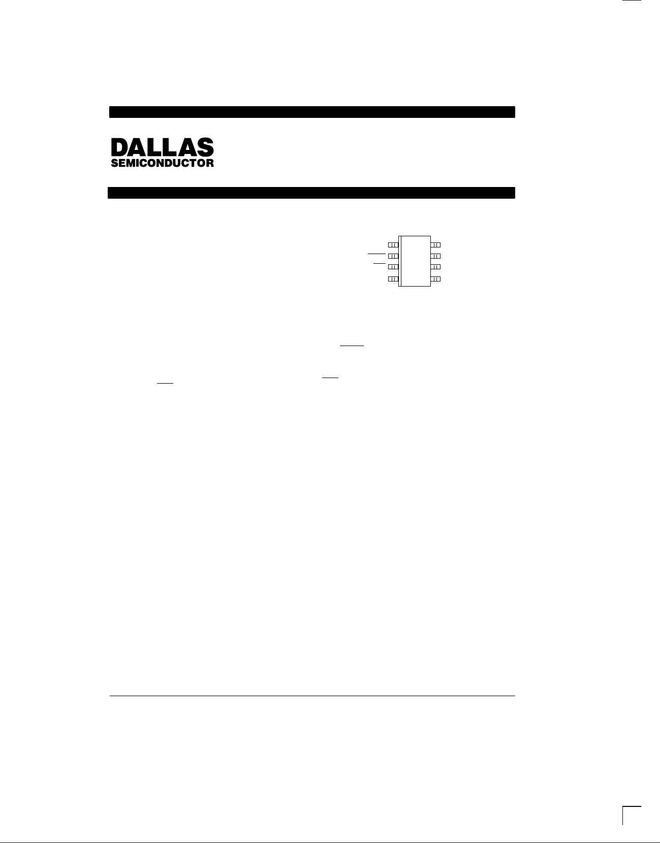
PIN ASSIGNMENT
1
DQ
CLK/CONV
RST
GND
DS1720S 8–PIN SOIC (208 MIL)
See Mech Drawings Section
8
V
2
3
4
DD
7
T
HIGH
6
T
LOW
5
T
COM
PIN DESCRIPTION
DQ – 3–Wire Input/Output
CLK/CONV
RST – 3–Wire Reset Input
GND – Ground
T
HIGH
T
LOW
T
COM
V
DD
– 3–Wire Clock Input and
Stand–alone
Convert Input
– High Temperature Trigger
– Low Temperature Trigger
– High/Low Combination Trigger
– Power Supply Voltage (3V – 5V)
DESCRIPTION
The DS1720 Digital Thermometer and Thermostat provides 9–bit temperature readings which indicate the
temperature of the device. With three thermal alarm outputs, the DS1720 can also act as a thermostat. T
driven high if the DS1720’s temperature is greater than
or equal to a user–defined temperature TH. T
driven high if the DS1720’s temperature is less than or
equal to a user–defined temperature TL. T
COM
HIGH
is
LOW
is driven
high when the temperature exceeds TH and stays high
until the temperature falls below that of TL.
User–defined temperature settings are stored in non–
is
volatile memory, so parts can be programmed prior to
insertion in a system, as well as used in stand–alone
applications without a CPU. Temperature settings and
temperature readings are all communicated to/from the
DS1720 over a simple 3–wire interface.
030598 1/12
Page 2
DS1720
OPERATION–MEASURING TEMPERATURE
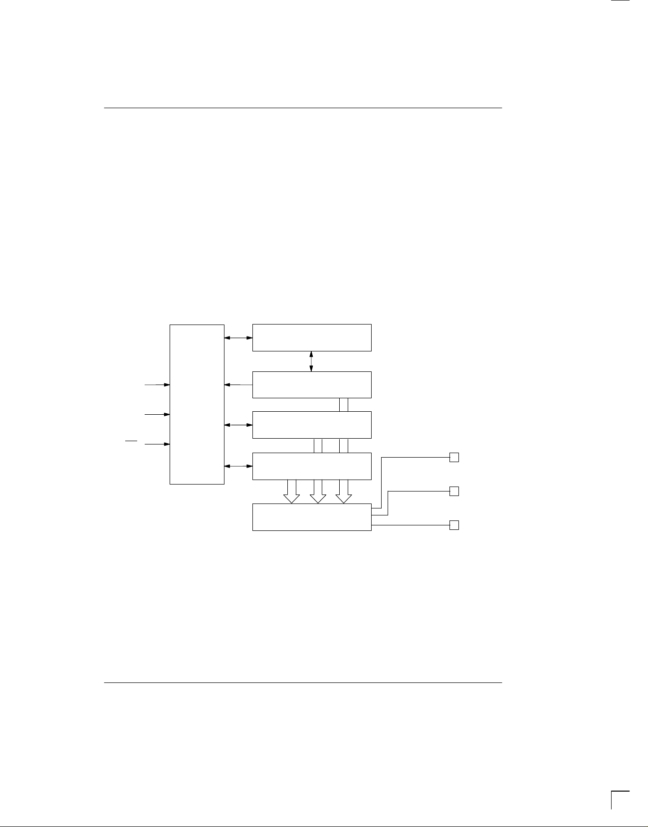
A block diagram of the DS1720 is shown in Figure 1.
The DS1720 measures temperatures through the use of
an on–board proprietary temperature measurement
technique. A block diagram of the temperature measurement circuitry is shown in Figure 2.
The DS1720 measures temperature by counting the
number of clock cycles that an oscillator with a low temperature coefficient goes through during a gate period
determined by a high temperature coefficient oscillator .
The counter is preset with a base count that corresponds to –55°C. If the counter reaches zero before the
gate period is over, the temperature register, which is
also preset to the –55°C value, is incremented, indicating that the temperature is higher than –55°C.
DS1720 FUNCTIONAL BLOCK DIAGRAM Figure 1
STATUS REGISTER AND
CONTROL LOGIC
CLK
DQ
ADDRESS
AND
RESET
TEMPERATURE SENSOR
HIGH TEMP TRIGGER, TH
At the same time, the counter is then preset with a value
determined by the slope accumulator circuitry . This circuitry is needed to compensate for the parabolic behavior of the oscillators over temperature. The counter is
then clocked again until it reaches zero. If the gate
period is still not finished, then this process repeats.
The slope accumulator is used to compensate for the
nonlinear behavior of the oscillators over temperature,
yielding a high resolution temperature measurement.
This is done by changing the number of counts necessary for the counter to go through for each incremental
degree in temperature. T o obtain the desired resolution,
therefore, both the value of the counter and the number
of counts per degree C (the value of the slope accumulator) at a given temperature must be known.
RST
030598 2/12
LOW TEMP TRIGGER, TL
DIGITAL COMPARATOR/LOGIC
T
T
T
HIGH
LOW
COM
Page 3
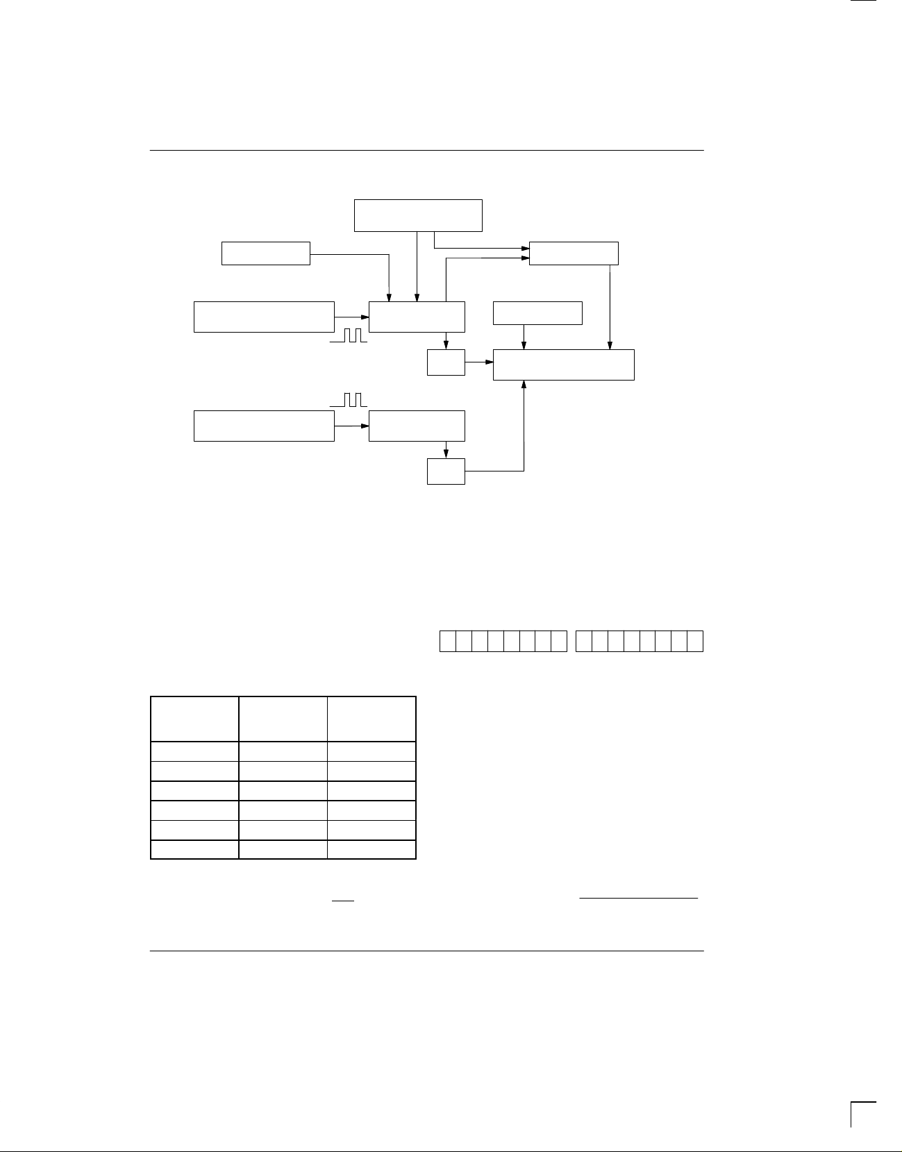
TEMPERATURE MEASURING CIRCUITRY Figure 2
SLOPE ACCUMULATOR
DS1720
PRESET
LOW TEMPERATURE
COEFFICIENT OSCILLATOR
HIGH TEMPERATURE
COEFFICIENT OSCILLATOR
COUNTER
COUNTER
This calculation is done inside the DS1720 to provide
0.5°C resolution. The temperature reading is provided
in a 9–bit, two’s complement reading by issuing a READ
TEMPERATURE command. Table 1 describes the
exact relationship of output data to measured temperature. The data is transmitted serially through the 3–wire
serial interface, LSB first. The DS1720 can measure
temperature over the range of –55°C to +125°C in 0.5°C
increments. For Fahrenheit usage, a lookup table or conversion factor must be used.
COMPARE
PRESET
INC
=0
STOP
=0
TEMPERATURE REGISTER
SET/CLEAR
LSB
9th (MSB) bit), or as two transfers of 8–bit words, with
the most significant 7 bits being ignored or set to zero,
as illustrated in T able 1. After the MSB, the DS1720 will
output 0s.
Note that temperature is represented in the DS1720 in
terms of a
MSB LSB
XXXXXXX1 11 0 01 11 0
1
/2°C LSB, yielding the following 9–bit format:
TEMPERATURE/DATA RELATIONSHIPS
T able 1
DIGITAL
OUTPUT
TEMP
(Binary)
+85°C 0 10101010 00AA
+25°C 0 00110010 0032h
1
+
°C 0 00000001 0001h
/2
+0°C 0 00000000 0000h
–1/2°C 1 11111111 01FFh
–25°C 1 11001110 01CEh
Since data is transmitted over the 3–wire bus LSB first,
temperature data can be written to/read from the
DS1720 as either a 9–bit word (taking RST low after the
DIGITAL
OUTPUT
(Hex)
T = –25°C
Higher resolutions may be obtained by reading the temperature, and truncating the 0.5°C bit (the LSB) from the
read value. This value is TEMP_READ. The value left in
the counter may then be read by issuing a READ
COUNTER command. This value is the count remaining (COUNT_REMAIN) after the gate period has
ceased. By loading the value of the slope accumulator
into the count register (using the READ SLOPE command), this value may then be read, yielding the number
of counts per degree C (COUNT_PER_C) at that temperature. The actual temperature may be then be calculated by the user using the following:
TEMPERATURE = TEMP_READ – 0.25
(COUNT_PER_C – COUNT_REMAIN)
COUNT_PER_C
030598 3/12
Page 4
DS1720
DETAILED PIN DESCRIPTION Table 2
PIN SYMBOL DESCRIPTION
1 DQ Data Input/Output pin for 3–wire communication port.
2 CLK/CONV Clock input pin for 3–wire communication port. When the DS1720 is used in a
3 RST Reset input pin for 3–wire communication port.
4 GND Ground pin.
5 T
6 T
7 T
8 V
COM
LOW
HIGH
DD
stand–alone application with no 3–wire port, this pin can be used as a convert pin.
Temperature conversion will begin on the falling edge of CONV
.
High/Low Combination Trigger. Goes high when temperature exceeds TH; will
reset to low when temperature falls below TL.
Low Temperature Trigger. Goes high when temperature falls below TL.
High Temperature Trigger. Goes high when temperature exceeds TH.
Supply Voltage. 2.7V – 5.5V input power pin.
OPERATION–THERMOSTAT CONTROLS
Three thermally triggered outputs, T
T
, are provided to allow the DS1720 to be used as a
COM
thermostat, as shown in Figure 3. When the DS1720’s
temperature meets or exceeds the value stored in the
high temperature trip register, the output T
becomes active (high) and remains active until the
DS1720’s measured temperature becomes less than
the stored value in the high temperature register, TH.
The T
output can be used to indicate that a high
HIGH
temperature tolerance boundary has been met or
exceeded, or as part of a closed loop system can be
used to activate a cooling system and to deactivate it
when the system temperature returns to tolerance.
The T
output functions similarly to the T
LOW
When the DS1720’s measured temperature equals or
HIGH
, T
HIGH
LOW
output.
, and
HIGH
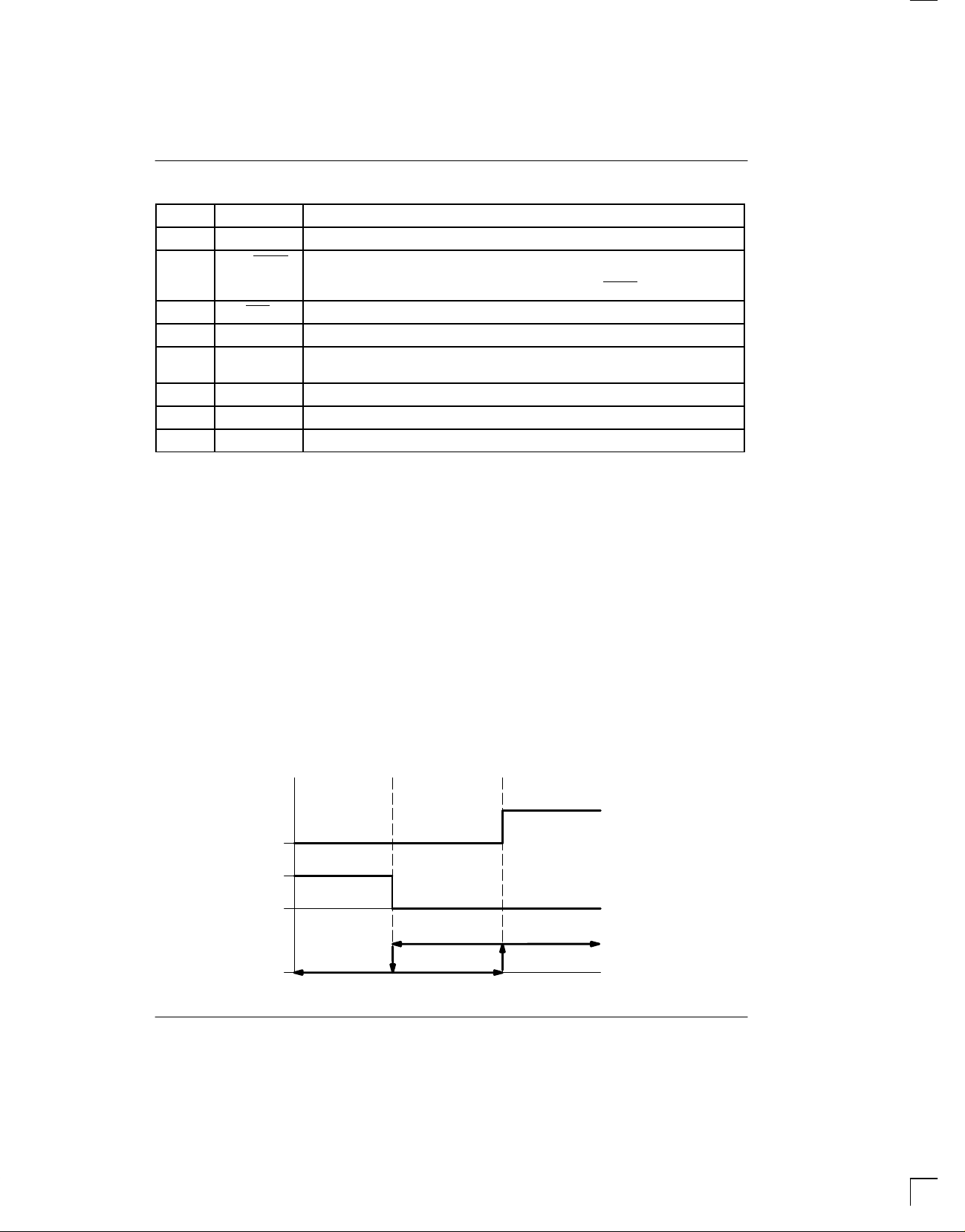
THERMOSTAT OUTPUT OPERATION Figure 3
T
HIGH
T
LOW
falls below the value stored in the low temperature register, the T
output becomes active. T
LOW
LOW
remains
active until the DS1720’s temperature becomes greater
than the value stored in the low temperature register,
TL. The T
output can be used to indicate that a low
LOW
temperature tolerance boundary has been met or
exceeded, or as part of a closed loop system, can be
used to activate a heating system and to deactivate it
when the system temperature returns to tolerance.
The T
output goes high when the measured tem-
COM
perature meets or exceeds TH, and will stay high until
the temperature equals or falls below TL. In this way,
any amount of hysteresis can be obtained.
030598 4/12
T
COM
TL TH
T (°C)
Page 5

DS1720
OPERATION AND CONTROL
The DS1720 must have temperature settings resident in
the TH and TL registers for thermostatic operation. A
configuration/status register is also used to determine
the method of operation that the DS1720 will use in a
particular application, as well as indicating the status of
the temperature conversion operation. The configuration register is defined as follows:
CONFIGURATION/STATUS REGISTER
DONE THF TLF NVB 1 0 CPU 1SHOT
where
DONE = Conversion Done bit. 1=conversion com-
plete, 0=conversion in progress.
THF = Temperature High Flag. This bit will be set
to 1 when the temperature is greater than
or equal to the value of TH. It will remain 1
until reset by writing 0 into this location or
by removing power from the device. This
feature provides a method of determining
if the DS1720 has ever been subjected to
temperatures above TH while power has
been applied.
TLF = Temperature Low Flag. This bit will be set
to 1 when the temperature is less than or
equal to the value of TL. It will remain 1
until reset by writing 0 into this location or
by removing power from the device. This
feature provides a method of determining
if the DS1720 has ever been subjected to
temperatures below TL while power has
been applied.
NVB = Nonvolatile Memory Busy Flag. 1=write to
CPU = CPU use bit. If CPU=0, the CLK/CONV
1SHOT = One–Shot Mode. If 1SHOT is 1, the
2
an E
memory cell in progress. 0=nonvolatile memory is not busy. A copy to E
may take up to 10 ms.
pin acts as a conversion start control,
when RST is low. If CPU is 1, the DS1720
will be used with a CPU communicating to
it over the 3–wire port, and the operation
of the CLK/CONV
pin is as a normal clock
in concert with DQ and RST. This bit is
stored in nonvolatile E2 memory, capable
of at least 50,000 writes. The DS1720 is
shipped with CPU=0.
DS1720 will perform one temperature
conversion upon reception of the Start
Convert T protocol. If 1SHOT is 0, the
DS1720 will continuously perform temperature conversion. This bit is stored in
nonvolatile E
2
memory, capable of at least
50,000 writes. The DS1720 is shipped
with 1SHOT=0.
For typical thermostat operation, the DS1720 will operate in continuous mode. However, for applications
where only one reading is needed at certain times, and
to conserve power, the one–shot mode may be used.
Note that the thermostat outputs (T
HIGH
will remain in the state they were in after the last valid
temperature conversion cycle when operating in one–
shot mode.
OPERATION IN STAND–ALONE MODE
In applications where the DS1720 is used as a simple
thermostat, no CPU is required. Since the temperature
limits are nonvolatile, the DS1720 can be programmed
prior to insertion in the system. In order to facilitate
operation without a CPU, the CLK/CONV
be used to initiate conversions. Note that the CPU bit
must be set to 0 in the configuration register to use this
mode of operation. Whether CPU=0 or 1, the 3–wire
port is active. Setting CPU=1 disables the stand–alone
mode.
To use the CLK/CONV
pin to initiate conversions, RST
must be low and CLK/CONV must be high. If CLK/
CONV is driven low and then brought high in less than
10 ms, one temperature conversion will be performed
and then the DS1720 will return to an idle state. If CLK/
is driven low and remains low, continuous con-
CONV
versions will take place until CLK/CONV is brought high
again. With the CPU bit set to 0, the CLK/CONV will
override the 1–shot bit if it is equal to 1. This means that
2
even if the part is set for one–shot mode, driving CLK/
low will initiate conversions.
CONV
3–WIRE COMMUNICATIONS
The 3–wire bus is comprised of three signals. These are
the RST (reset) signal, the CLK (clock) signal, and the
DQ (data) signal. All data transfers are initiated by driving the RST
nates communication. (See Figures 4 and 5). A clock
cycle is a sequence of a falling edge followed by a rising
edge. For data inputs, the data must be valid during the
rising edge of a clock cycle. Data bits are output on the
input high. Driving the RST input low termi-
, T
, T
LOW
COM
pin (pin 2) can
)
030598 5/12
Page 6

DS1720
falling edge of the clock, and remain valid through the
rising edge.
When reading data from the DS1720, the DQ pin goes
to a high impedance state while the clock is high. T aking
RST
low will terminate any communication and cause
the DQ pin to go to a high impedance state.
Data over the 3–wire interface is communicated LSB
first. The command set for the 3–wire interface as
shown in Table 3 is as follows; only these protocols
should be written to the DS1720, as writing other protocols to the device may result in permanent damage to
the part.
Read Temperature [AAh]
This command reads the contents of the register which
contains the last temperature conversion result. The
next nine clock cycles will output the contents of this register.
Write TH [01h]
This command writes to the TH (HIGH TEMPERATURE) register. After issuing this command, the next
nine clock cycles clock in the 9–bit temperature limit
which will set the threshold for operation of the T
output.
HIGH
Write TL [02h]
This command writes to the TL (LOW TEMPERATURE) register. After issuing this command, the next
nine clock cycles clock in the 9–bit temperature limit
which will set the threshold for operation of the T
output.
LOW
Read TH [A1h]
This command reads the value of the TH (HIGH TEMPERATURE) register. After issuing this command, the
next nine clock cycles clock out the 9–bit temperature
limit which sets the threshold for operation of the T
output.
HIGH
Read TL [A2h]
This command reads the value of the TL (LOW TEMPERATURE) register. After issuing this command, the
next nine clock cycles clock out the 9–bit temperature
limit which sets the threshold for operation of the T
output.
LOW
Read Counter [A0h]
This command reads the value of the counter byte. The
next nine clock cycles will output the contents of this
register.
Read Slope [A9h]
This command reads the value of the slope counter byte
from the DS1720. The next nine clock cycles will output
the contents of this register.
Start Convert T [EEh]
This command begins a temperature conversion. No
further data is required. In one–shot mode, the temperature conversion will be performed and then the DS1720
will remain idle. In continuous mode, this command will
initiate continuous conversions.
Stop Convert T [22h]
This command stops temperature conversion. No further data is required. This command may be used to halt
a DS1720 in continuous conversion mode. After issuing
this command, the current temperature measurement
will be completed, and then the DS1720 will remain idle
until a Start Convert T is issued to resume continuous
operation.
Write Config [0Ch]
This command writes to the configuration register. After
issuing this command, the next eight clock cycles clock
in the value of the configuration register.
Read Config [ACh]
This command reads the value in the configuration register. After issuing this command, the next eight clock
cycles output the value of the configuration register.
030598 6/12
Page 7

DS1720 COMMAND SET Table 3
3–WIRE BUS
DATA AFTER
ISSUING
INSTRUCTION DESCRIPTION PROTOCOL
TEMPERATURE CONVERSION COMMANDS
Read Temperature Reads last converted temperature
AAh <read data>
value from temperature register
Read Counter Reads value of count remaining from
A0h <read data>
counter
Read Slope Reads value of the slope accumulator A9h <read data>
Start Convert T Initiates temperature conversion EEh Idle 1
Stop Convert T Halts temperature conversion 22h Idle 1
THERMOSTAT COMMANDS
Write TH Writes high temperature limit value into
01h <write data> 2
TH register
Write TL Writes low temperature limit value into
02h <write data> 2
TL register
Read TH Reads stored value of high tempera-
A1h <read data> 2
ture limit from TH register
Read TL Reads stored value of low temperature
A2h <read data> 2
limit from TL register
Write Config Writes configuration data to configura-
0Ch <write data> 2
tion register
Read Config Reads configuration data from configu-
ACh <read data> 2
ration register
PROTOCOL
DS1720
NOTES
NOTES:
1. In continuous conversion mode, a Stop Convert T command will halt continuous conversion. T o restart, the Start
Convert T command must be issued. In one–shot mode, a Start Convert T command must be issued for every
temperature reading desired.
2
2. Writing to the E
should be requested for at least 10 ms.
typically requires 10 ms at room temperature. After issuing a write command, no further writes
030598 7/12
Page 8

DS1720
FUNCTION EXAMPLE
Example: CPU sets up DS1720 for continuous conversion and thermostatic function.
CPU MODE
TX RX 0Ch CPU issues Write Config command
TX RX 00h CPU sets DS1720 up for continuous conversion
TX RX Toggle RST CPU issues Reset to DS1720
TX RX 01h CPU issues Write TH command
TX RX 0050h CPU sends data for TH limit of +40°C
TX RX Toggle RST CPU issues Reset to DS1720
TX RX 02h CPU issues Write TL command
TX RX 0014h CPU sends data for TL limit of +10°C
TX RX Toggle RST CPU issues Reset to DS1720
TX RX A1h CPU issues Read TH command
RX TX 0050h DS1720 sends back stored value of TH for CPU
TX RX Toggle RST CPU issues Reset to DS1720
TX RX A2h CPU issues Read TL command
RX TX 0014h DS1720 sends back stored value of TL for CPU
TX RX Toggle RST CPU issues Reset to DS1720
TX RX EEh CPU issues Start Convert T command
TX RX Toggle RST CPU issues Reset to DS1720
DS1720 MODE
(3–WIRE)
DATA (LSB FIRST) COMMENTS
to verify
to verify
030598 8/12
Page 9

READ DATA TRANSFER Figure 4
DS1720
RST
t
CC
CLK
t
CDH
DQ
t
DC
017
WRITE DATA TRANSFER Figure 5
RST
t
CLK
DQ
CC
t
DC
017
t
CDH
t
CL
PROTOCOL
t
R
t
CH
t
CCH
t
CDD
LSB
DATA
t
DC
LSB
DATA
t
DCH
t
F
MSB
DATA
t
CCH
t
CDZ
MSB
DATA
t
CWH
t
RDZ
PROTOCOL
NOTE: tCL, tCH, tR, and tF apply to both read and write data transfer.
RELATED APPLICATION NOTES
The following Application Notes can be applied to the
DS1720. These notes can be obtained from the Dallas
Semiconductor “Application Note Book”, via our website at http:\\www.dalsemi.com/, or through our faxback
service at (972) 371–4441.
Application Note 67
in T emperature Control Applications”
: “Applying and Using the DS1620
Application Note 85
: “Interfacing the DS1620 to the Mo-
torola SPI Bus”
Application Note 105
: “High Resolution Temperature
Measurement with Dallas Direct–to–Digital Temperature Sensors”
Sample DS1720 subroutines that can be used in conjunction with AN105 can be downloaded from the website or our Anonymous FTP Site.
030598 9/12
Page 10

DS1720
ABSOLUTE MAXIMUM RATINGS*
Voltage on Any Pin Relative to Ground –0.5V to +7.0V
Operating Temperature –55°C to +125°C
Storage Temperature –55°C to +125°C
Soldering Temperature 260°C for 10 seconds
* This is a stress rating only and functional operation of the device at these or any other conditions above those
indicated in the operation sections of this specification is not implied. Exposure to absolute maximum rating
conditions for extended periods of time may affect reliability.
The Dallas Semiconductor DS1720 is built to the highest quality standards and manufactured for long term reliability.
All Dallas Semiconductor devices are made using the same quality materials and manufacturing methods. However,
the DS1720 is not exposed to environmental stresses, such as burn–in, that some industrial applications require. For
specific reliability information on this product, please contact the factory in Dallas at (972) 371–4448.
RECOMMENDED DC OPERATING CONDITIONS
PARAMETER SYMBOL MIN TYP MAX UNITS NOTES
Supply V
Logic 1 V
Logic 0 V
DD
IH
IL
2.7 5.5 V 1
2.0 VCC+0.3 V 1
–0.3 +0.6 V 1
DC ELECTRICAL CHARACTERISTICS (–55°C to +125°C; VDD=2.7V to 5.5V)
PARAMETER SYMBOL CONDITION MIN MAX UNITS NOTES
Thermometer Error T
Logic 0 Output V
Logic 1 Output V
Input Resistance R
Active Supply Current I
Standby Supply Current I
STBY
ERR
OL
OH
I
CC
0°C to 85°C ±2.5 °C 10, 11
–55°C to
+125°C
See Typical Curve
0.4 V 3
2.4 V 2
RST to GND
DQ,CLK to V
DD
2
2
MΩ
MΩ
0°C to +70°C 1 mA 4, 5
0°C to +70°C 1 µA 4, 5
SINGLE CONVERT TIMING DIAGRAM (STAND–ALONE MODE)
CONV
t
CNV
030598 10/12
Page 11

DS1720
AC ELECTRICAL CHARACTERISTICS (–55°C to +125°C; VDD=2.7V to 5.5V)
PARAMETER SYMBOL MIN TYP MAX UNITS NOTES
Temperature Conversion Time T
Data to CLK Setup t
CLK to Data Hold t
CLK to Data Delay t
CLK Low Time t
CLK High Time t
CLK Frequency f
DC
CDH
CDD
CL
CH
CLK
CLK Rise and Fall tR, t
RST to CLK Setup t
CLK to RST Hold t
RST Inactive Time t
CLK High to I/O High–Z t
RST Low to I/O High–Z t
Convert Pulse Width t
NV Write Cycle Time t
CC
CCH
CWH
CDZ
RDZ
CNV
WR
TC
35 ns 6
40 ns 6
285 ns 6
285 ns 6
DC 1.75 MHz 6
F
100 ns 6
40 ns 6
125 ns 6, 9
250 ns 500 ms
400 1000 ms
100 ns 6, 7, 8
500 ns
50 ns 6
50 ns 6
10 50 ms 12
AC ELECTRICAL CHARACTERISTICS (–55°C to +125°C; VDD=2.7V to 5.5V)
PARAMETER SYMBOL MIN TYP MAX UNITS NOTES
Input Capacitance C
I/O Capacitance C
I
I/O
5 pF
10 pF
NOTES:
1. All voltages are referenced to ground.
2. Logic one voltages are specified at a source current of 1 mA.
3. Logic zero voltages are specified at a sink current of 4 mA.
specified with DQ pin open and CLK pin at VDD.
4. I
CC
specified with VCC at 3.3V and RST=GND.
5. I
CC
6. Measured at V
7. Measured at V
8. Load capacitance = 50 pF.
9. t
must be 10 ms minimum following any write command that involves the E2 memory.
CWH
10.See typical curve for specification limits outside 0°C to 85°C range.
11.Thermometer error reflects temperature accuracy as tested during calibration.
12.Writing to the nonvolatile memory should only take place in the 0°C to 70°C temperature range.
= 2.0V or VIL = 0.6V.
IH
= 2.4V or VOL = 0.4V.
OH
030598 11/12
Page 12

DS1720
DS1720 TYPICAL THERMOMETER ERROR
DS1720 TYPICAL THERMOMETER ERROR
4
3
UPPER SPEC
LIMIT
–55 –25 –10 5 20 45 60 75 90 100
THERMOMETER ERROR (C)
2
1
–1
–2
–3
–4
–5
–6
AMBIENT TEMPERATURE (C)
TYPICAL ERROR
LOWER SPEC
LIMIT
125
030598 12/12
 Loading...