

Page 1
Note:
Some revisions of this device may incorporate deviations from published specifications known as errata. Multiple
channels. For information about device
ALARM
ALARM
ALARM
ALARM
1
6 3 2
8 4 5 7
DS1682
www.maxim
-
ic.com
FEATURES
§ Records the total time that the event input has
been active and the number of events that
have occurred
§ 32-bit, nonvolatile, elapsed time counter
monitors event duration with quarter-second
resolution and provides 34 years of total t ime
accumulation
§ Programmable elapsed time
§ Nonvolatile 17-bit event counter records the
total number of times an event has occurred
§ Calibrated, temperature-compensated RC
time base accurate to 2% typical
§ 10 bytes of EEPROM user memory
§ Write disable function to prevent the memory
from being changed or erased
§ 2-wire serial communication
§ Wide power-supply range (2.5V to 5.5V)
§ Useful in time-of -use warranty, calibration,
repair, and maintenance applications
output
Total Elapsed Time Recorder
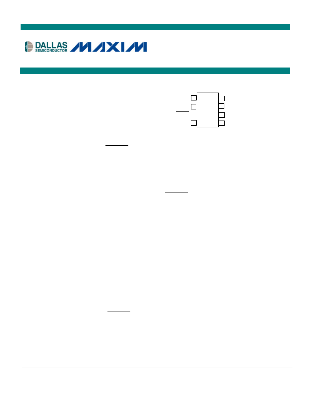
PIN ASSIGNMENT
EVENT
N/C
ALARM
GND
DS1682
DS1682S 8-Pin SO (150mil)
Top View
Package dimension information can be found at:
http://dbserv.maxim-ic.com/products.cfm
PIN DESCRIPTION
EVENT - Event Input
- Alarm Output
GND - Ground
SDA - Serial-Data I/O
SCL - Serial-Clock Input
VCC - Voltage Supply
N/C - No Connect
V
N/C
SDA
with Alarm
CC
SCL
ORDERING INFORMATION
DS1682S 8-Pin SO (150mil) -40°C to +85°C
DESCRIPTION
The DS1682 is an integrated elapsed time recorder containing a factory-calibrated, temperaturecompensated RC time base that eliminates the need for an external crystal. Using EEPROM technology
to maintain data in the absence of power, the DS1682 requires no backup power source. The DS1682
detects and records the number of events on the EVENT pin and the total cumulative event time since the
DS1682 was last reset to 0. The
user-programmed alarm value. The polarity of the open-drain
drive low or to become high impedance upon an alarm condition. The DS1682 is ideal for applications
that monitor the total amount of time that a device has been in operation and/or the number of uses since
inception of service, repair, or the last calibration.
pin alerts the user when the total time accumulated equals the
pin can be programmed to either
revisions of any device may be simultaneously available through various sales
errata, click here: http://dbserv.maxim-ic.com/errata.cfm.
1 of 15 041202
Page 2
DS1682
A
OPERATION
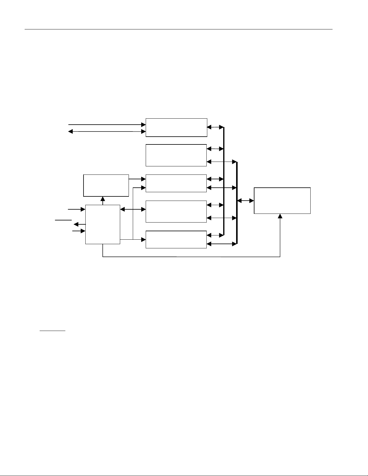
The block diagram in Figure 1 shows the relationship between the major functional blocks, the serial
interface, and the EEPROM memory section of the DS1682. Upon power-up, the DS1682 transfers the
contents of the EEPROM into the counters and memory registers where the data can be read and written
through the serial interface. The content of the counters and memory registers are written into the
EEPROM memory when the EVENT pin transitions from a logic high to a logic low.
Figure 1. BLOCK DIAGRAM
SCL
SDA
OSCILLATOR
AND
DIVIDER
V
CC
LARM
EVENT
CONTROL
LOGIC
AND
EVENT
GLITCH
FILTER
The DS1682 uses a calibrated, temperature-compensated RC time base to increment an elapsed time
counter (ETC) while an event is active. When the event becomes active, the contents of the nonvolatile
EEPROM are transferred to the ETC and event counter and the oscillator starts. As the event continues,
the ETC is incremented in quarter-second increments. When the event becomes inactive, the event
counter is incremented and the contents of the ETC and event counter are written to the nonvolatile
EEPROM.
ALARM output can be used to indicate when the ETC has matched the value in the alarm register.
The
The DS1682 can be configured to prevent clearing the alarm and the elapsed time and event counters.
The user memory can be separately write-protected.
SERIAL
INTERFACE
USER, CONTROL, AND
CONFIGURATION
REGISTERS
ELAPSED TIME
COUNTER (ETC)
ALARM REGS
AND
COMPARE LOGIC
EVENT COUNTER
EEPROM ARRAY
2 of 15
Page 3

SIGNAL DESCRIPTIONS
V
– VCC is a +2.5V to +5.5V input supply.
CC
DS1682
GND – Ground.
SCL (2-Wire Serial-Clock Input) – The SCL pin is the serial-clock input for the 2-wire synchronous
communications channel. The SCL pin is an input that requires an external pullup resistor.
SDA (2-Wire Input/Output) – The SDA pin is the data input/output signal for the 2-wire synchronous
communications channel. The SDA pin is an open-drain I/O, which requires an external pullup resistor.
EVENT (Event Input) – The EVENT pin is the input the DS1682 monitors to determine when an event
occurs. When the pin is pulled high, the contents of the EEPROM are transferred to the ETC and the
oscillator starts. The ETC will begin to count in quarter-second increments. When the EVENT pin falls to
a logic 0, the event counter increments and the event counter, ETC, and user-memory data are stored in
the EEPROM array. When the EVENT pin changes states, the 2-wire bus is unavailable for
communications for tEW. The EVENT input is also deglitched (tG) to prevent short noise spikes from
triggering an event.
ALARM (Alarm Output) – The DS1682 monitors the values in the ETC for the programmed value in the
alarm register. When the ETC matches the alarm value, the alarm flag (AF) is set. Once set, the alarm
flag cannot be reset. See the operating descriptions for the AOS and AP bits for details about the
operation of the ALARM pin.
N/C (No Connect) – This pin is not connected internally.
3 of 15
Page 4

Figure 2. MEMORY MAP
DS1682
ADDR BIT 7 BIT 6 BIT 5 BIT 4 BIT 3 BIT 2 BIT 1 BIT 0 FUNCTION
00 0 AF WDF WMDF AOS RE AP ECMSB
Configuration
Register
01 Low Byte
02 Low-Middle Byte
03 High-Middle Byte
Alarm Register
04 High Byte
05 Low Byte
06 Low-Middle Byte
07 High-Middle Byte
08 High Byte
09 Low Byte
0A High Byte
Elapsed
Time
Counter
(ETC)
Event
Counter
0B Byte 1
0C Byte 2
0D Byte 3
0E Byte 4
0F Byte 5
10 Byte 6
User Memory
11 Byte 7
12 Byte 8
13 Byte 9
14 Byte 10
15
16
17
18
19
Not Used (reads 00h) Not Used
1A
1B
1C
1D Reset Command Reset Command
1E Write Disable Write Disable
1F Write Memory Disable Memory Disable
User-modified data are not stored in EEPROM until an event becomes inactive.
4 of 15
Page 5
DS1682
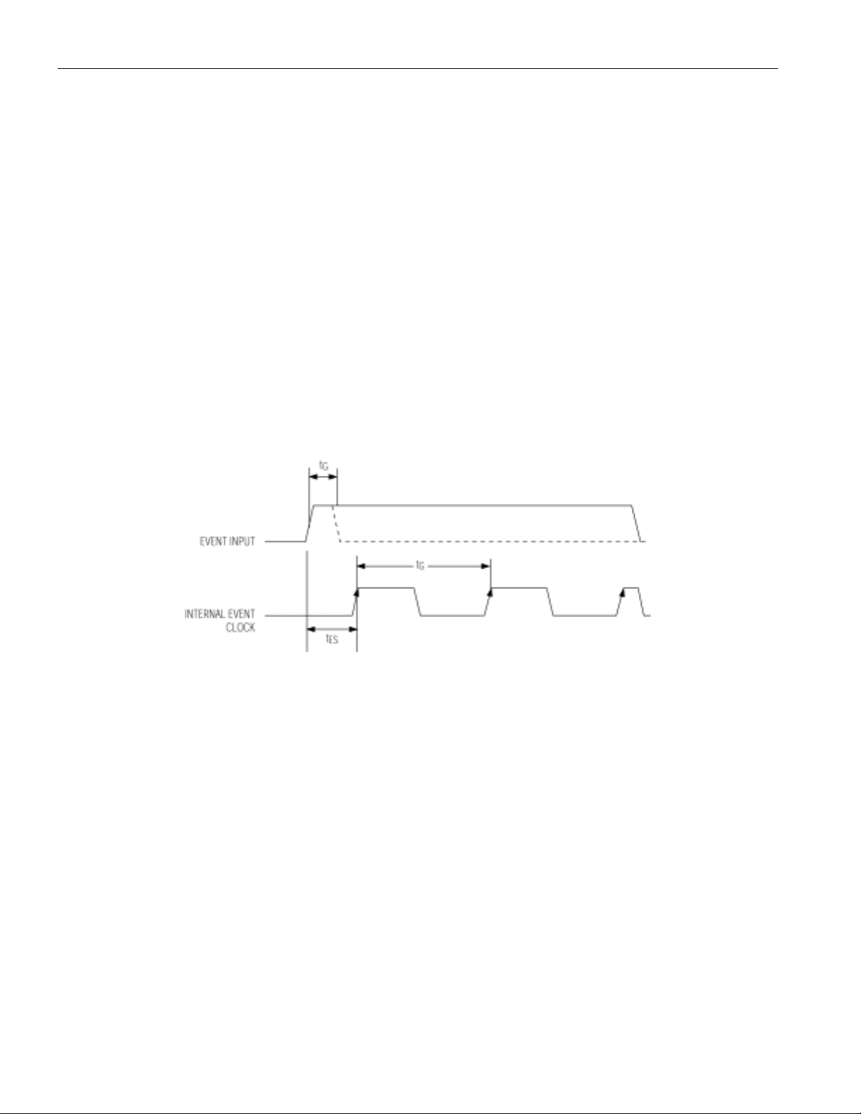
EVENT LOGGING
When the DS1682 is powered up, the event time and count values recorded in the EEPROM are
transferred to the ETC and event counter and the device waits for an event. When an event triggers the
input by transitioning the EVENT pin from a low to a high level, the following occurs:
1) The RC oscillator starts.
2) The alarm, ETC, and event counter are transferred from EEPROM to RAM.
Note: Reading the RAM during the transfer will result in invalid data.
3) After tES, the ETC increments. An event greater than tG but less than tES increments the event counter
but not the ETC (zero-length event).
4) The ETC increments every TEI. The ETC holds time in quarter-second resolution.
5) When the EVENT pin goes low, the event counter increments, the oscillator stops, and the ETC and
event counter are transferred to EEPROM. The 2-wire bus is not available for t
See Figure 3 for timing.
The ETC stops counting and does not roll over once FFFFFFFFh, or approximately 34 years, is reached.
Figure 3. EVENT INPUT TIMING
EW
.
DEVICE SETUP
Once installed in a system, the DS1682 can be programmed to record events as required by the
application, and can be tested by generating events and monitoring the results. Afterwards, it can be
“locked” to prevent alteration of the event and alarm registers and the alarm condition.
The following is a typical sequence:
1) Write the configuration register, alarm registers, and user memory to the desired values.
2) Write-protect the alarm, ETC, and event counter registers with the write disable command if needed.
3) Write-protect the user memory with the write-memory disable command, if needed.
4) Issue a reset (described in the Reset Command section).
The alarm, ETC and event counter registers, and user memory, once locked, cannot be changed.
Upon reset, the ETC and event counter registers are cleared. The RE bit is cleared by the device, and the
configuration register becomes read-only. Additional resets are ignored.
5 of 15
Page 6

DS1682
ALARM
The alarm register is a 32-bit register that holds time in quarter-second resolution. When a nonzero
number is programmed into the alarm register, the ALARM function is enabled and the DS1682
monitors the values in the ETC for the programmed value in the alarm register. When the ETC matches
the alarm value, the alarm flag is set.
EEPROM ARRAY
When power is applied, the contents of the EEPROM are transferred to the configuration register, alarm
register, ETC, event counter, and user memory. VCC slew rate tPU must be met to ensure the data transfer.
In addition, t
must also be met for proper data transfer. If tPU and t
OFF
cannot be ensured, the event pin
OFF
must not go active until VCC is stable and above VCC min for at least 100ms. An external reset circuit can
be used if needed.
The EEPROM array for the ETC and the event counter is made up of three banks. Each bank can be
written a maximum of 50k times. The device switches between banks based upon the value in the event
counter. Resetting the event counter before the counter reaches 50,000 will cause additional writes to the
first bank, which can allow writes in excess of 50k. If the event counter is set to greater than 50k or 100k
prior to reset, the device stays on the selected bank. This could result in writes in excess of 50k to one
bank.
The configuration and alarm registers and the user memory are held in one bank of EEPROM. Writes at
the end of an event only occur if the data has changed in one or more of those registers.
User-modified data in any of the registers is stored in EEPROM only if the data was written while an
event was active and is stored when the event ends.
EVENT COUNTER REGISTER
This 17-bit event counter register set provides the total number of data samples logged during the life of
the product up to 131,072 separate events. The event counter consists of 2 bytes of memory in the
memory map plus the event counter MSB bit (ECMSB) in the configuration register. Once the event
counter reaches 1FFFFh, event counting stops.
RESET COMMAND
If RE is set to a 1, a reset occurs when a reset command is sent through the 2-wire bus. A reset command
is issued by writing 55h twice into memory location 1Dh.
Upon reset, the ETC and event counter registers will be cleared. The AF, RE, and ECMSB bits are
cleared by the device, and the configuration register becomes read-only. The data are written to the
EEPROM, and additional resets are ignored.
When a reset command is issued, no additional command should be issued during the EEPROM write
time (tEW).
6 of 15
Page 7

DS1682
CONFIGURATION REGISTER
MSb
0 AF WDF WMDF AOS RE AP ECMSB
Note: The configuration register is not stored in EEPROM until an event becomes inactive. RE does not
need to be stored in EEPROM to reset the device.
AF (Alarm Flag) – The alarm flag is set to a 1 when the ETC value matches the alarm register. Once the
AF bit is set to a 1, it cannot be set to a 0. This bit is read-only.
WDF (Write Disable Flag) – When the write disable command is written to AAh twice at memory
location 1Eh, the WDF is set to a 1 and cannot be cleared or reset. When WDF is set to a 1, the alarm,
ETC, and event counter registers are read-only. This bit is read-only.
WMDF (Write-Memory Disable Flag) – When the write-memory disable command is written to F0h
twice at memory location 1Fh, the WMDF is set to a 1 and cannot be reset or cleared. Once the WMDF is
set to a 1, the 10-byte user memory becomes read-only. This bit is read-only.
AOS (Alarm Output Select) – If AOS is 0 and AF is true, the DS1682 activates the ALARM output
during an event when AF becomes true. The DS1682 also activates the ALARM output by pulling the
pin low four times at power-up, at the start and end of an event, or when the ALARM pin is pulled low
and released. This output mode can be used to flash an LED or to communicate with another device to
indicate that an alarm has occurred. AP has no affect on the output when AOS is 0.
If AOS is a 1 and AF is true, the ALARM output is constant when the alarm is active. AP determines the
polarity of the output.
RE (Reset Enable) – The reset enable bit allows the device to be reset by enabling the reset command.
The sections of the DS1682 that are reset are then dependent on the value in the WDF. With the WDF set
to 0 and the reset enable bit set to a 1, the reset command clears the ETC, EEPROM, and event counter.
When the reset enable bit is set to a 0, the reset command is disabled.
AP (Alarm Polarity) – When the alarm polarity bit in the configuration register is set to 0, the
output is high impedance during the period that the value in the ETC is less than the alarm register value.
When the ETC matches the alarm value, the
ALARM output is driven low during the period that the ETC is less than the alarm value. When the ETC
matches the alarm value, the ALARM pin becomes high impedance. The AP bit has no affect if AOS is
set to a 0.
ECMSB (Event Counter MSB) – This bit is read-only.
LSb
ALARM
ALARM pin is driven low. If the AP bit is set to a 1, the
USER MEMORY
There are 10 bytes of user-programmable, EEPROM memory. Once the write-memory disable flag is set
to a 1, the memory becomes read-only. User memory is not stored in EEPROM until an event becomes
inactive.
7 of 15
Page 8

DS1682
2-WIRE SERIAL DATA BUS
The DS1682 supports a bidirectional, 2-wire bus and data-transmission protocol. A device that sends data
onto the bus is defined as a transmitter and a device receiving data, a receiver. The device that controls
the message is called a master, and the devices controlled by the master are slaves. The bus must be
controlled by a master device that generates the serial clock (SCL), controls the bus access, and generates
the START and STOP conditions. The DS1682 operates as a slave on the 2-wire bus. Connections to the
bus are made through the open-drain I/O lines SDA and SCL.
The following bus protocol has been defined (Figure 4):
Data transfer can be initiated only when the bus is not busy.
During data transfer, the data line must remain stable whenever the clock line is HIGH. Changes in
the data line while the clock line is high are interpreted as control signals.
Figure 4. TIMING DIAGRAM: DATA TRANSFER ON 2-WIRE SERIAL BUS
8 of 15
Page 9

DS1682
Accordingly, the following bus conditions have been defined:
Bus Not Busy: Both data and clock lines remain HIGH.
Start Data Transfer: A change in the state of the data line, from HIGH to LOW, while the clock is
HIGH, defines a START condition.
Stop Data Transfer: A change in the state of the data line, from LOW to HIGH, while the clock line is
HIGH, defines the STOP condition.
Data Valid: The state of the data line represents valid data when, after a START condition, the data line
is stable for the duration of the HIGH period of the clock signal. The data on the line must be changed
during the LOW period of the clock signal. There is one clock pulse per bit of data.
Each data transfer is initiated with a START condition and terminated with a STOP condition. The
number of data bytes transferred between START and STOP conditions is not limited, and is determined
by the master device. The information is transferred byte-wise and each receiver acknowledges with a
ninth bit. Within the bus specifications a standard mode (100kHz clock rate) and a fast mode (400kHz
clock rate) are defined.
Acknowledge: Each receiving device, when addressed, is obliged to generate an acknowledge after it
receives each byte. The master device must generate an extra clock pulse, which is associated with this
acknowledge bit.
A device that acknowledges must pull down the SDA line during the acknowledge clock pulse in such a
way that the SDA line is stable LOW during the HIGH period of the acknowledge-related clock pulse. Of
course, setup and hold times must be considered. A master must signal an end-of-data to the slave by not
generating an acknowledge bit on the last byte that has been clocked out of the slave. In this case, the
slave must leave the data line HIGH to enable the master to generate the STOP condition.
Depending upon the state of the R/W bit, two types of data transfer are possible:
1) Data transfer from a master transmitter to a slave receiver. The first byte transmitted by the
master is the slave address. Next follows a number of data bytes. The slave returns an acknowledge
bit after each received byte.
2) Data transfer from a slave transmitter to a master receiver. The first byte (the slave address) is
transmitted by the master. The slave then returns an acknowledge bit. Next follows a number of data
bytes transmitted by the slave to the master. The master returns an acknowledge bit after all received
bytes other than the last byte. A “not acknowledge” is returned at the end of the last received byte.
The master device generates all of the serial clock pulses and the START and STOP conditions. A
transfer is ended with a STOP condition or with a repeated START condition. Since a repeated START
condition is also the beginning of the next serial transfer, the bus will not be released.
9 of 15
Page 10

A
A
A
A
A
A
A
A
DS1682
The DS1682 can operate in the following two modes:
1) Slave Receiver Mode (DS1682 Write Mode): Serial data and clock are received through SDA and
SCL. After each byte is received, the receiver transmits an acknowledge bit. START and STOP
conditions are recognized as the beginning and end of a serial transfer. The slave address byte is the
first byte received after the start condition is generated by the master. The address byte contains the 7bit DS1682 address, which is 1101011, followed by the direction bit (R/W). The second byte from the
master is the register address. This sets the register pointer. The master then transmits each byte of
data, with the DS1682 acknowledging each byte received. The master will generate a stop condition
to terminate the data write (Figure 5).
Figure 5. DATA WRITE, SLAVE RECEIVER MODE
SLAVE
ADDRESS
1101011
S
S - Start
A - Acknowledge
P - Stop
R/W - Read/Write or Direction Bit
R/W
0
REGISTER
XXXXXXXX
DATA(n) DATA(n+1)
XXXXXXXX
XXXXXXXX
(X + 1 Bytes + Acknowledge)
XXXXXXXX
Data Transferred
DATA(n+x)
P
2) Slave Transmitter Mode (DS1682 Read Mode): The first byte is received and handled as in the
slave receiver mode. However, in this mode, the direction bit indicates that the transfer direction is
reversed. Serial data is transmitted on SDA by the DS1682 while the serial clock is input on SCL. The
slave address byte is the first byte received after the start condition is generated by the master. The
address byte contains the 7-bit DS1682 address, followed by the direction bit (R/W). After receiving a
valid slave address byte and direction bit, the DS1682 generates an acknowledge on the SDA line.
The DS1682 begins to transmit data on each SCL pulse starting with the register address pointed to by
the register pointer. As the master reads each byte, it must generate an acknowledge. The DS1682
must receive a “not acknowledge” on the last byte to end a read (Figure 6).
Figure 6. DATA READ, SLAVE TRANSMITTER MODE
ADDRESS
1101011
S
SLAVE
R/W
1
DATA(n)
XXXXXXXX
DATA(n+1)
XXXXXXXX
XXXXXXXX
DATA(n+x) DATA(n+2)
XXXXXXXX /A
S - Start
A - Acknowledge
P - Stop
/A - Not Acknowledge
R/W - Read/Write or Direction Bit
(X + 1 Bytes + Acknowledge)
10 of 15
Data Transferred
Page 11

DS1682
ABSOLUTE MAXIMUM RATINGS*
Voltage Range on Any Pin Relative to Ground -0.3V to +6V
Operating Temperature Range -40°C to +85°C
Storage Temperature Range -55°C to +125°C
Soldering Temperature Range See IPC/JEDEC J-STD-020A specification
*This is a stress rating only and functional operation of the device at these or any other conditions beyond
those indicated in the operation sections of this specification is not implied. Exposure to absolute
maximum rating conditions for extended periods of time can affect reliability.
RECOMMENDED DC OPERATING CONDITIONS (-40°C to +85°C)
PARAMETER SYMBOL MIN TYP MAX UNITS NOTES
Power-Supply Voltage VCC 2.5 5.5 V
Input Trip Point V
Event Trip-Point Hysteresis V
0.3 x VCC 0.5 x V
ETP
1% of VCC %
HYS
0.7 x VCC V
CC
DC ELECTRICAL CHARACTERISTICS (-40°C to +85°C; VCC = 2.5V to 5.5V)
PARAMETER SYMBOL MIN TYP MAX UNITS NOTES
Input Leakage ILI -1 +1
µA
ALARM Output (IOL = 10mA) VOL 0.8 V
SDA Output (IOL = 4mA) VOL 0.8 V
Active Supply Current
I
120 300
CCA
µA
4
(Event Active)
Standby Current VCC = 5.5V
(Event Inactive) VCC = 3.0V
EEPROM Write Current IEE 150 300
I
6 2 15
CCS
4
µA
µA
4
4
EVENT TIMING (-40°C to +85°C; VCC = 2.5V to 5.5V)
PARAMETER SYMBOL MIN TYP MAX UNITS NOTES
Time Event Minimum tG 10 35 70 ms 4
Time Event Start tES 112 125 137 ms 4
Time Event Increment tEI 237.5 250 262.5 ms 4
Time Event Max tEM 34 years
TRANSISTOR COUNT: 26,032
PROCESS: CMOS
11 of 15
Page 12

DS1682
AC ELECTRICAL CHARACTERISTICS (-40°C to +85°C; VCC = 2.5V to 5.5V)
PARAMETER SYMBOL CONDITIONS MIN TYP MAX UNITS NOTES
EEPROM Endurance EE 50k writes 2
EEPROM Write Time tEW 150 300 ms 1,3,4
EEPROM Transfer to
RAM
ALARM Output
Active-Low Pulse
Width
ALARM Output
Active-High Pulse
Width
ALARM Input Pulled
Low and Released
Pulse Width
SCL Clock Frequency f
Bus Free Time
Between a STOP and
START Condition
Hold Time (Repeated)
START Condition
t
LOW Period of SCL t
HIGH Period of SCL t
Setup Time for a
Repeated START
t
Data Hold Time t
Data Setup Time t
Rise Time of SDA and
SCL Signals
Fall Time of SDA and
SCL Signals
Setup Time for STOP t
tER 1 ms 4,5
tSL 62.5 ms 4
tSH 437.5 ms 4
t
500 ms 4
SPL
SCL
Fast Mode 400
Standard Mode 100
kHz
Fast Mode 1.3
t
BUF
µs
Standard Mode 4.7
HD:STA
LOW
Fast Mode 0.6
Standard Mode 4.0
Fast Mode 1.3
Standard Mode 4.7
µs
µs
6
Fast Mode 0.6
HIGH
Standard Mode 4.0
µs
Fast Mode 0.6
SU:STA
HD:DAT
Standard Mode 4.7
Fast Mode 0
Standard Mode 0
µs
µs
7, 8
Fast Mode 100
SU:DAT
tR
tF
SU:STO
Standard Mode 250
Fast Mode
Standard Mode
Fast Mode
Standard Mode
Fast Mode 0.6
Standard Mode 4.0
20 + 0.1CB
20 + 0.1CB
20 + 0.1CB
20 + 0.1CB
300
1000
300
300
ns 10
ns 9
ns 9
µs
Input Capacitance C
Capacitive Load for
Each Bus Line
10 pF 4
I/O
CB 400 pF 9
12 of 15
Page 13

DS1682
Figure 7. TIMING DIAGRAM
NOTES:
1) VCC must be at or above 2.5V for tEW after the end of an event to insure data transfer to the EEPROM.
2) The elapsed time and event counters are backed by three EEPROM arrays which are used
sequentially, allowing up to 3 x EE. The configuration register, alarm trip-point register and user
memory use a single array, limiting them to one EE.
3) A decoupling capacitor to supply high instantaneous currents during EEPROM writes is
recommended. A typical value is 0.01µF. VCC must be maintained above Vcc minimum, including
transients, during EEPROM writes.
4) Typical values are at +25°C, VCC = 4.0V.
5) Reading data while the contents of EEPROM are transferred to RAM results in incorrect reads.
6) After this period, the first clock pulse is generated.
7) A device must internally provide a hold time of at least 300ns for the SDA signal (referred to the
V
8) The maximum t
SCL signal.
9) CB–Total capacitance of one bus line in pF.
10) A fast-mode device can be used in a standard-mode system, but the requirement t
be met. This is automatically the case if the device does not stretch the t
stretch t
before the SCL line is released.
of the SCL signal) in order to bridge the undefined region of the falling edge of SCL.
IHMIN
has only to be met if the device does not stretch the low period (t
HD:DAT
. If such a device does
LOW
, it must output the next data bit to the SDA line tR max + t
LOW
= 1000 + 250 = 1250ns
SU:DAT
≥ 250ns must
SU:DAT
LOW
) of the
13 of 15
Page 14

Figure 8. TOTAL RUN TIME
DS1682
Figure 8 shows the DS1682 measuring total run time and operating from a battery with the alarm tied to
an LED and a pushbutton switch to trigger the alarm output.
Figure 9. TOTAL TIME-OF-USE APPLICATION WITH FAST VCC SLEW RATE
Figure 9 shows the DS1682 in a total time-of-use application where power may be removed at the same
time as the end of the event. The V
slew rate at power-down is fast with respect to tEW. A capacitor
CC
maintains VCC on the DS1682 above 2.5V until the EEPROM write completes. A Schottky diode blocks
current from the capacitor to other devices connected to V
CC
.
The VCC holding capacitor value of 30µF is calculated using the maximum EEPROM write current and
EEPROM write time. This assumes that the V
2.5V on the DS1682 is at least t
EW.
slew rate allows time from EVENT trip point to VCC at
CC
14 of 15
Page 15

DS1682
Figure 10. TOTAL TIME-OF-USE APPLICATION WITH SLOW VCC SLEW RATE
Figure 10 shows the DS1682 in a total time-of-use application with power that can be removed at the
same time as the end of the event. In this application, the V
respect to tEW. The external RST IC ends the event as V
until the end of t
EW
.
CC
slew rate at power-down is slow with
CC
begins to drop. VCC must remain above 2.5V
15 of 15
 Loading...