

Page 1

AMS0805WAH
CATALOG No.:
2008.03
AMS0805WAH
Motion Sensor Data Sheet
Ver. 1.3
Advanced Material on Technolog y
Page 2

AMS0805WAH
MOTION SENSOR
Overview
Motion sensor is a 6-axis module consisting of 3-axis magnetic sensor and 3-axis
accelerometer. It allows highly accurate motion detection with geomagnetic direction and tilting
data. AMS0805WAH is a world’s smallest class of motion sensor module with embedded uCom.
Moreover, our exclusive embedded calibration algorithm, iRAC, eliminates the need for initial
manual calibrations. It also enables users to access to reliable motion data virtually anywhere.
Therefore, motion sensor is suitable for deployment in hand-held devices, where diverse
movements are constantly expected, in order to acquire accurate positioning and direction data.
Features
● a 3-axis accelerometer, a 3-axis magnetic sensor
● an internal micro-processor
● Built-in software (for auto-calibration)
● Serial interface: IIC, SPI
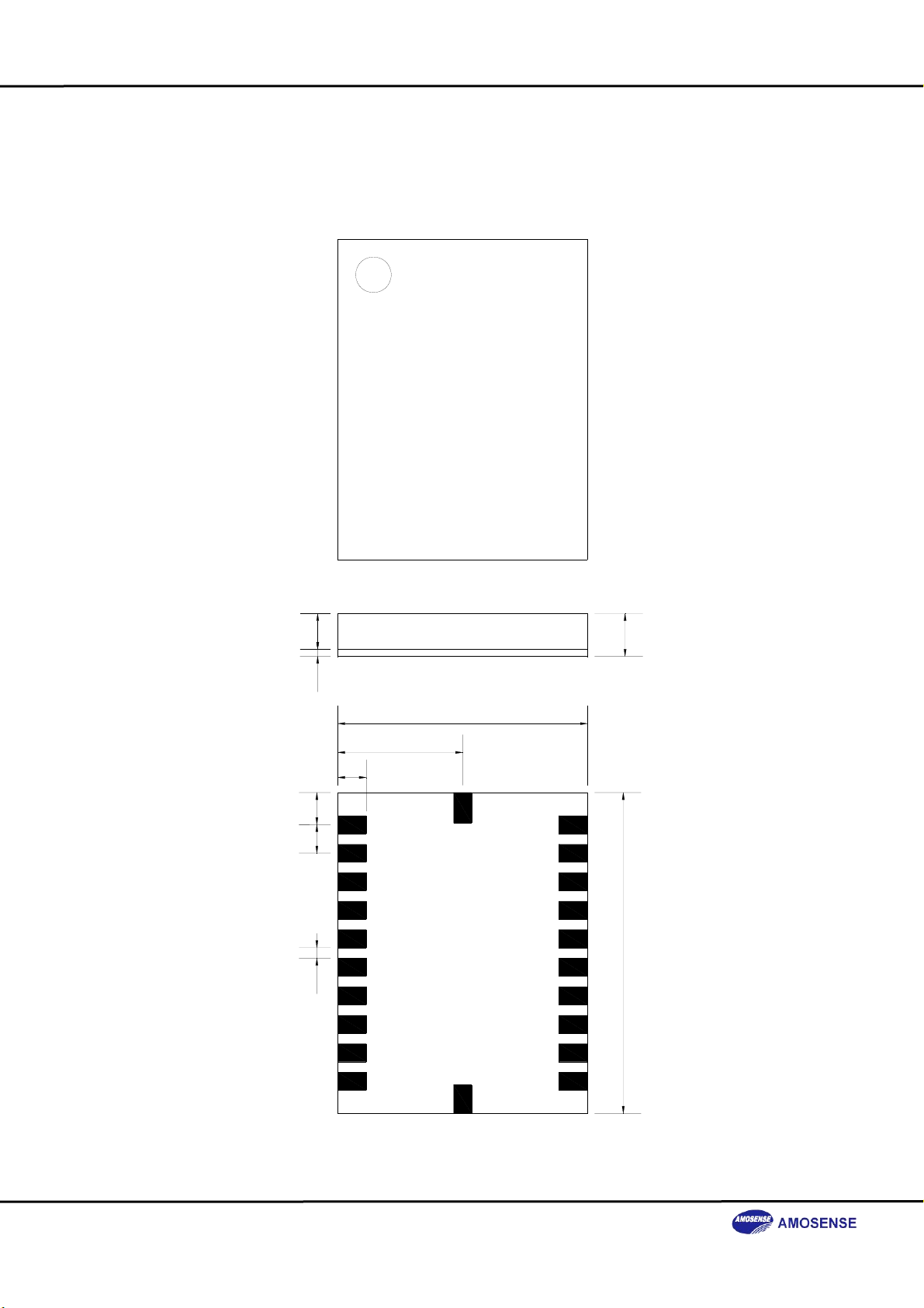
● Size: 7 X 9 X 1.2 (mm)
● iRAC (Intelligent Real time Automatic Calibration)
- Automatic offset compensation
- Automatic temperature compensation
- Automatic sensitivity calibration
- Automatic calibration for magnetic field disturbance
● Maximum sampling rate : 30Hz
● Low power: less than 9 mA in active
less than 20 uA in all power down mode
Applications
● Personal Navigation in mobile phone
● Calorie counter
● Constellation seeking device
● Robot motion control
● 3-D presenter
● Game controller
2
Page 3
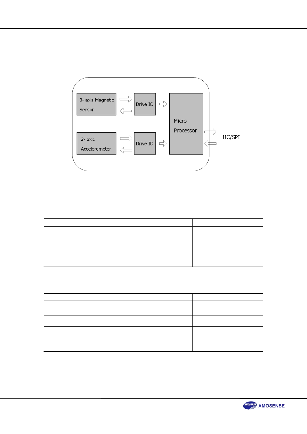
Functional Block Diagram
Absolute Maximum Ratings
Item Symbol Min. Max. Unit Description
DC Supply Voltage
(DVDD,DVDDIO,AVDD)
Storage Temperature
Range
Mechanical Shock - - + 4,600 g
ESD - - + 2,000 V
- - 0.3 + 4 V
- - 55 + 125 ℃
AMS0805WAH
MOTION SENSOR
Recommended Operating Conditions
Item Symbol Min. Max. Unit Description
Operating DVDD Supply
Voltage Range
Operating AVDD Supply
Voltage Range
Operating DVDDIO
Supply Voltage Range
Operating Temperature
Range
- + 2.7 + 3.4 V
- + 2.7 + 3.4 V
- + 1.8 + 3.4 V
- - 20 + 85 ℃
3
Page 4
Compass Specifications
Item Min. Typ. Max. Unit Description
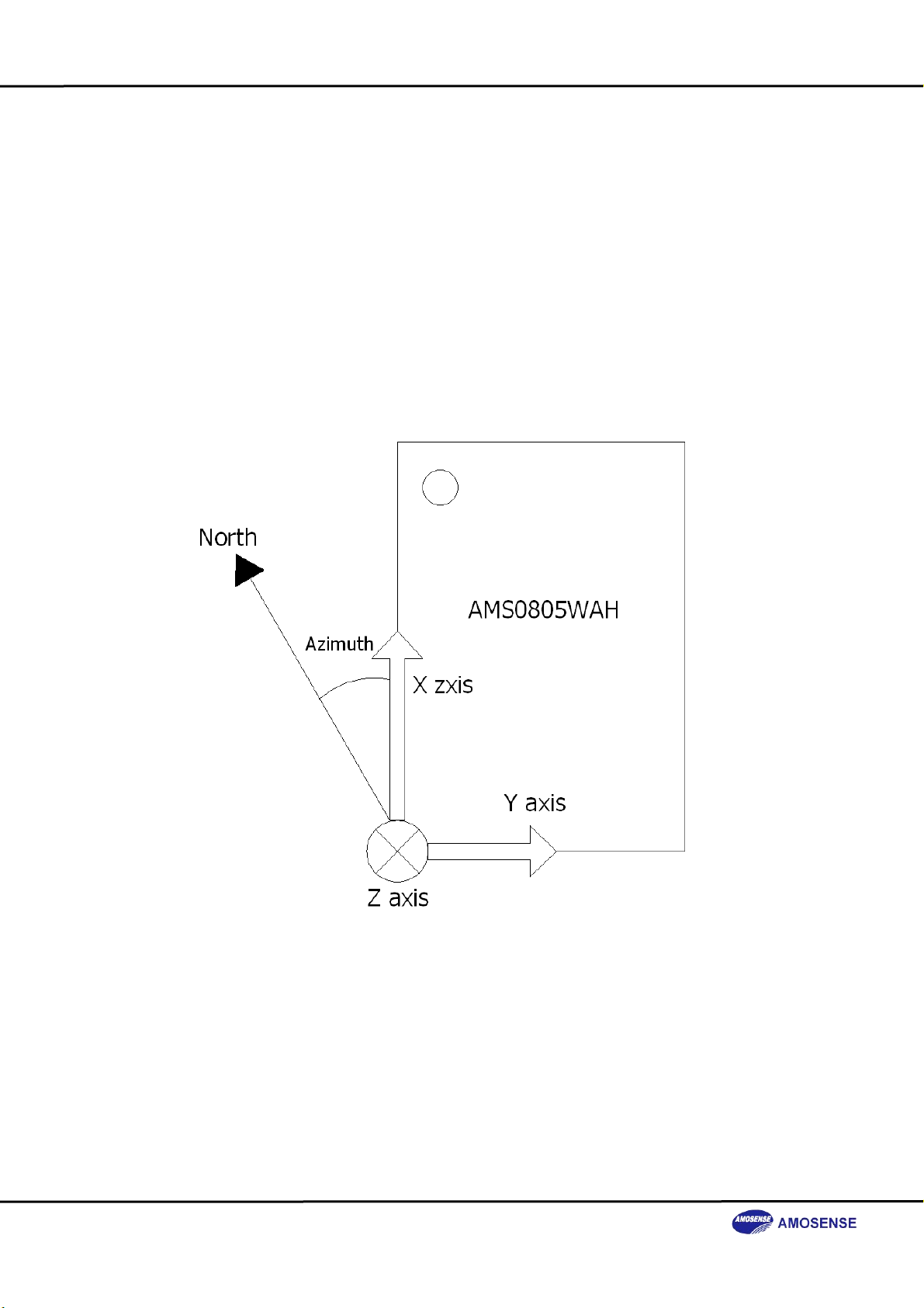
Azimuth accuracy - 5 - + 5 degree
Azimuth range 0 - 359 degree
Azimuth resolution - 1 - degree
Flux density measurement
range
Maximum sampling rate - - 30 Hz
Power consumption - - 27 mW Power down : 60 uW(@ 3.0 V)
Roll/pitch compensation
range
Roll/pitch resolution - 1 - degree
Roll/pitch accuracy - 5 - + 5 degree
- 1,000 - + 1,000 μT
- 89 - + 89 degree
DC characteristics
At. DVDD & DVDDIO = 2.7~3.4V Ta= -20 ~85℃℃
Item Symbol Min. Max. Unit Description
Input high voltage 1 VIH1 0.7 x DVDD DVDD + 0.6 V All Digital I/O Port except RESET
Input high voltage 2 VIH2 0.9 x DVDD DVDD + 0.6 V /RESET(Schmitt input)
Input low voltage 1 VIL1 -0.5 0.3 x DVDD V All Digital I/O Port except RESET
Input low voltage 2 VIL2 -0.5 0.3 x DVDD V /RESET(Schmitt input)
IIC characteristics
At. DVDDIO = 2.7~3.4V Ta= -20 ~85℃℃
Parameter Max. Units Description
Clock Frequency 400 kHz SCL
Sink Current 2 mA SDA, SCL
AMS0805WAH
MOTION SENSOR
SPI characteristics
At. DVDDIO = 2.7~3.4V Ta= -20 ~85℃℃
Parameter Max. Units Description
Clock Frequency 1 MHz SCK
4
Page 5
A
A
A
A
A
A
A
Pin Descriptions
● Serial Interface
Pin name Pin No. Pin type Initial Function
NC / /SS 3 DI
NC / MOSI 2 DI
SDA / MISO 1 DIO / DO
SCL / SCK 4 DI - Clock.
IIC / SPI 7 DI - L : SPI, H : IIC
3-states
H
3-states
H
Z
H
● Power
Pin name Pin No. Pin type Function
DVDD 12,18 PWR Digital power supply
DVDDIO 13 PWR Digital I/O power supply (See page )
DVSS 5,14,22 PWR GND for digital.
VDD 8 PWR
VSS 10 PWR GND for analog.
● NC for only Testing
Pin name Pin No. Function
NC 9,11,15,16 For only test
● Etc
Pin name Pin No. Pin type Initial Function
/RESET 6 DSI H Reset pin, active "L", Schmitt input.
/WAKE_UP 17 DI H Wake up signal : active "L"
X-
xis Accelerometer analog output.
AXOUT 19 AO -
AYOUT 21 AO -
AZOUT 20 AO -
External capacitor must be connected for stable signal
( 100nF )
xis Accelerometer analog output.
YExternal capacitor must be connected for stable signal
( 100nF )
xis Accelerometer analog output.
ZExternal capacitor must be connected for stable signal
( 100nF )
Note
DI: Digital input DO: Digital output
DSI: Digital Schmitt input AO: Analog output
DIO: Digital bi-directional PWR: Power
IIC mode: NC.
SPI mode: Slave - Selection pin.
IIC mode: NC.
SPI mode: Master-Output, Slave-Input.
IIC mode: SD
SPI mode: Master-Input, Slave-Output.
nalog power supply.
AMS0805WAH
MOTION SENSOR
5
Page 6
AMS0805WAH
MOTION SENSOR
Package Information (unit: mm)
DVSS
22
SDA/MISO
NC/MOSI
NC//SS
SCL/SCK
DVSS
/RESET
IIC/SPI
AVDD
NC
AVSS
1
2
3
4
5
6
7
8
9
10
Top view
11
NC
21
20
19
18
17
16
15
14
13
12
AY OUT
AZ OUT
AX OUT
DVDD
/WAKE_UP
NC
NC
DVSS
DVDDIO
DVDD
1
0,2
0,8
Side view
3,5
1,2
7
0,90,80,3
21
22
1
Bottom view
9
12
10
11
6
Page 7
AMS0805WAH
MOTION SENSOR
A P P E N D I X
Coordinate system
Basically, the
right thumb into the positive rotation axis and curl your fingers into the forward rotational direction.
right-hand rule
is used for determining the sign of a rotation: point your
7
Page 8
AMS0805WAH
MOTION SENSOR
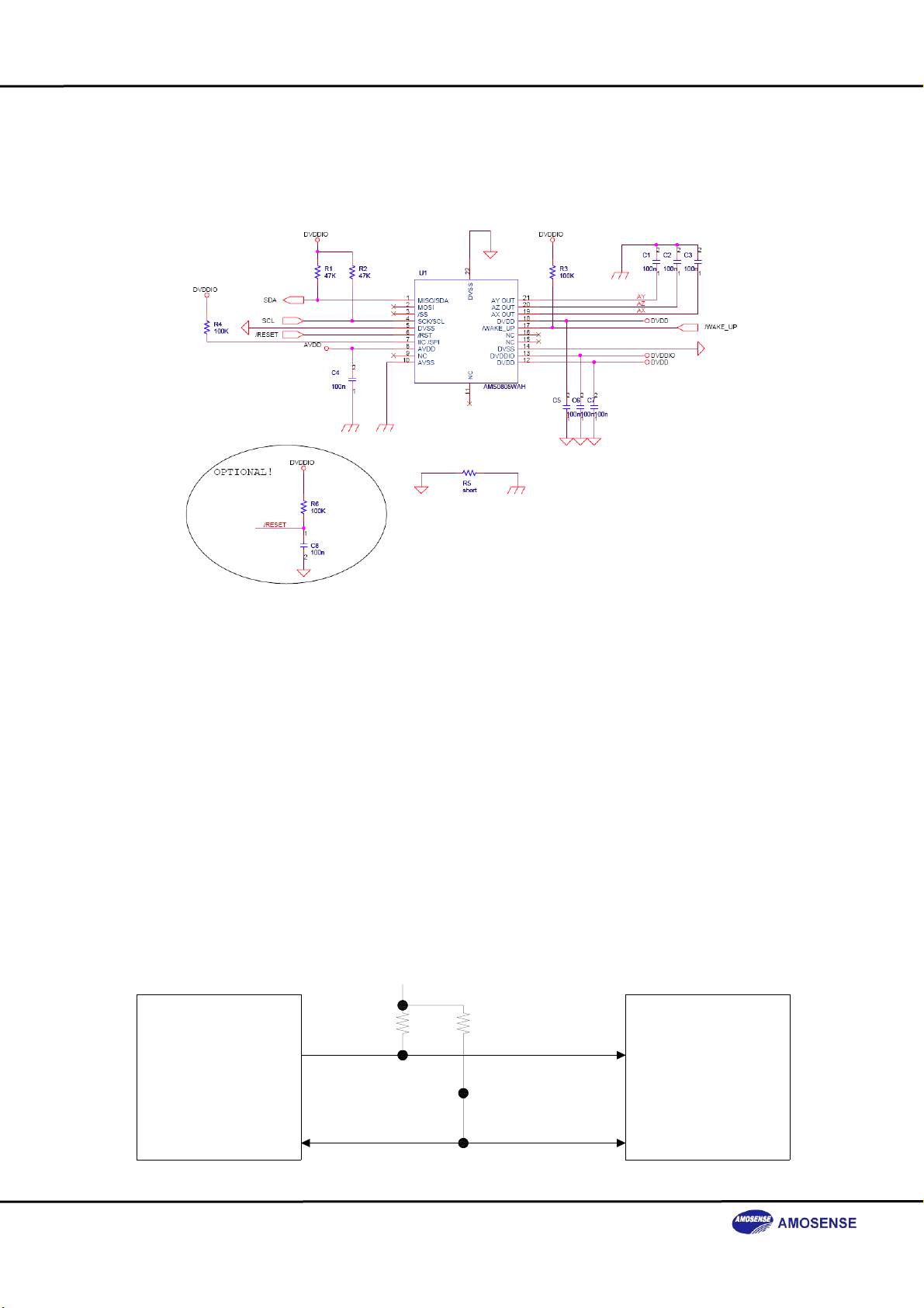
Typical Connection ( IIC default )
IIC Serial Peripheral Interface
IIC is suited for typical micro-controller. It is designed to easily connect any µcom to IIC
compliant slave. The 2 required lines on the slave side are the clock (SCL) signal and the data
(SDA) signal.
Typical Operating Circuit
● Typical Connection
VDD
Master Controller
(MCU)
IIC
Serial
I/F
SCL
SDA
8
SCL
Slave Device
SDA
Page 9
AMS0805WAH
MOTION SENSOR
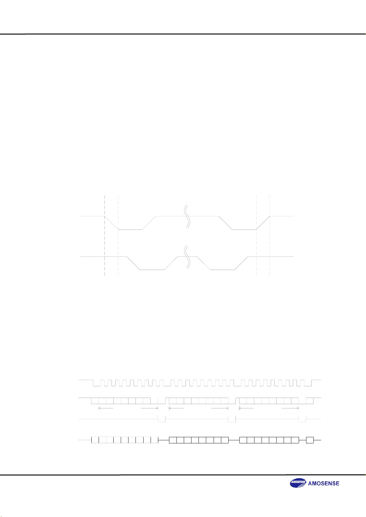
Protocol
● Transaction Rules
Each data transferred on the SDA is accompanied by a pulse on the clock signal. The
data on the SDA must be stable when the clock is high. The only exception is for generating start
and stop. The master initiates and terminates a data transmission.
Start condition
Stop condition
SDA
SCL
acknowledgement. It starts by a start condition and ends by a stop condition. The first byte is the
Slave Address, the second is the Register Address and the third is the Data Byte. The LSB of the
Slave Code byte is the R/W indicator.
MASTER Transmit & SLAVE Receive
SCL
SDA
SDA SLAVE
SDA MASTER
: To start reading/writing operation, it is necessary to generate a start condition by
switching the SDA input from high level to low level when the SCL input is high
level.
: To stop reading/writing operation, it is necessary to generate stop condition by
switching the SDA input from low level to high level when the SCL input is high
level. When the stop condition is generated, the operation is stopped, the data
is processed and the system enters in standby mode.
Start
Stop
● Single-Byte Write Sequence
The Single Byte Write Sequence is composed of 3 bytes of 9 bits, the 9
0
0S65
1
MSB LSB MSB LSB MSB LSB
10100XW0S6
00XWA
1
Slave address
765
AAA
3
4
Command
5
4321076
21
0A
7P
th
bit being the
3
4
21
Data
5
432107P
0A
9
Page 10

● Single-Word Read Sequence
There is no Single-Byte Read Sequence, so that "DEV_ID" and "REVNUM" should be
read at word length if it would be read. In this case, upper byte of the word is "zero" and the valid
data is in lower byte. Only Word read sequence is provided as following:
MASTER Transmit & SLAVE Receive
SCL
SDA
SDA MASTER
MASTER Receive & SLAVE Transmit
SCL
SDA
SDA SLAVE
SDA MASTER
Here, Command means Register Address actually.
0
0S65
1
MSB LSB MSB LSB
1
1010 0XRA
0S6
MSB LSB MSB LSB MSB LSB
1010 0XR0S P
00XWA
1
Slave address
0
00XW0S65
1
Slave address
AMS0805WAH
MOTION SENSOR
7P
AASDA SLAVE
76
A
6
3
4
Write Data
3
4
5
43210A
Data H
5
4321076
0A
21
07P
21
5
7P
5
AA
TO MASTER Transmit
43210A
Data
432107
10
Page 11

AMS0805WAH
MOTION SENSOR
● Slave & Register address
The 7bit field is slave code field. The last bit on the SDA is Read/Write bit.
● Slave address field
Bit NAME Value Description
Bit[7...0] Slave address
01010000(=0x50)
01010001(=0x51)
● Register Field
Bit NAME Range Description
Bit[7...0] Register address 0x01 ~ 0x34 Internal register address
Write Sequence
Read Sequence
11
Page 12

AMS0805WAH
MOTION SENSOR
Typical Connection ( SPI [OPTION] )
SPI Serial Peripheral Interface (Original SPI)
The Serial Peripheral Interface (SPI) is a 4-wire Clock Synchronous Serial Interface. It
is designed to easily connect any CPU to SPI compliant slaves using only 3 lines plus one chip
select line per slave. Few slaves can be connected on the CPU SPI. The 4 required lines on the
slave side for the SPI are MISO, MOSI, SCK signal and /SS signal.
● Typical Operating Circuit
- Typical Connection with one Slave
Master Controller
(MCU)
SPI
Serial I/F
/CS
SCK
MOSI
MISO
12
/SS
SCK
Slave Device 1
MOSI
MISO
Page 13

AMS0805WAH
MOTION SENSOR
- Typical Connection with two Slaves
/CS
Master Controller
(MCU)
SPI
Serial I/F
SCK
MOSI
MISO
/SS
SCK
Slave Device 1
MOSI
MISO
/SS
SCK
Slave Device 2
MOSI
MISO
Protocol
The data format is MSB in first and LSB in last.
● Single Byte Write Sequence
/SS
SCK
MOSI
MISO
76543
MSB LSB MSB LSB
Commend & Register Byte
21
0
76543
● Single Byte Read Sequence
/SS
SCK
MOSI
MISO 7 6 5
76543
MSB LSB
Commend & Register Byte
21
0
MSB LSB
13
Data Byte
4
Data Byte
21
3
21
0
0
Page 14

AMS0805WAH
MOTION SENSOR
● Multi Byte Read Sequence
/SS
SCK
MOSI
MISO
76543
MSB LSB
Commend & Register Byte
21
0
76543210
MSB LSB
Data Byte 1
(Adress)
76543210
MSB LSB
Data Byte 2
(Address + 1)
14
Page 15

Register Table
Register Symbol R/W Explanation
01(h) DEV_ID R Device ID
02(h) REVNUM R Revision Number
03(h) MAG_STATUS R Big Magnetic Field Status Flag
14(h) POWER W Power Down Mode
20(h) AZIMUTH_H R MSB of AZIMUTH
21(h) AZIMUTH_L R LSB of AZIMUTH
22(h) MAG_XH R MSB of Magnetic Sensor X axis
23(h) MAG_XL R LSB of Magnetic Sensor X axis
24(h) MAG_YH R MSB of Magnetic Sensor Y axis
25(h) MAG_YL R LSB of Magnetic Sensor Y axis
26(h) MAG_ZH R MSB of Magnetic Sensor Z axis
27(h) MAG_ZL R LSB of Magnetic Sensor Z axis
28(h) CAL_XH R MSB of slope compensated X axis
29(h) CAL_XL R LSB of slope compensated X axis
2A(h) CAL_YH R MSB of slope compensated Y axis
2B(h) CAL_YL R LSB of slope compensated Y axis
2C(h) ACC_XH R MSB of Accelerometer X axis
2D(h) ACC_XL R LSB of Accelerometer X axis
2E(h) ACC_YH R MSB of Accelerometer Y axis
2F(h) ACC_YL R LSB of Accelerometer Y axis
30(h) ACC_ZH R MSB of Accelerometer Z axis
31(h) ACC_ZL R LSB of Accelerometer Z axis
32(h) PITCH_H R MSB of PITCH angle
33(h) PITCH_L R LSB of PITCH angle
34(h) ROLL_H R MSB of ROLL angle
35(h) ROLL_L R LSB of ROLL angle
AA(h) CAL_ACC W Accelerometer Offset Calibration Mode ( See page 22~26 )
AMS0805WAH
MOTION SENSOR
15
Page 16

AMS0805WAH
MOTION SENSOR
Register Descriptions
01(h) "DEV_ID" Device ID Register
Device ID 04H
02(h) "REVNUM" Revision number Register
Revision number 20H
03(h) "MAG_ALARM" External Big Magnetic Field Status Flag
- No External Big Magnetic Field condition 00H
- External Big Magnetic Field condition 01H
z This register is operated over than 0.4gauss external magnetic field distortion.
(In this condition, the Azimuth of AMS0805WAH may be directed wrong,
You need to calibration AMS0805WAH)
14(h) "AMS_POWER" Power Management Register
Registers Descriptions
00h(W)
01h(W)
ACTIVE : ALL POWER ON
(Magnetic sensor ON, Accelerometer ON, MICOM ON)
POWER DOWN: ALL POWER OFF
(Magnetic sensor OFF, Accelerometer OFF, MICOM OFF)
02(h) POWER SAVE: Magnetic sensor OFF, Accelerometer ON, MICOM ON
20(h) ~ 21(h) "AZIMUTH"
- Direction of AMS0805WAH
- Data range: 0 ~ 360
- Resolution: 1 degree
22(h) ~ 23(h) "MAG_X"
- X axis Magnetic flux density value
24(h) ~ 25(h) "MAG_Y"
- Y axis Magnetic flux density value
26(h) ~ 27(h) "MAG_Z"
- Z axis Magnetic flux density value
16
Page 17

AMS0805WAH
MOTION SENSOR
28(h) ~ 29(h) "CAL_X"
- Slope compensated X axis Magnetic flux density value
2A(h) ~ 2B(h) "CAL_Y"
- Slope compensated Y axis Magnetic flux density value
2C(h) ~ 2D(h) "ACC_X"
- X axis Acceleration value
- Data range: - 2,048 ~ 2,047
- Resolution: 1 counts = 0.01225m/s
2E(h) ~ 2F(h) "ACC_Y"
- X axis Acceleration value
- Data range: -2,048 ~ 2,047
- Resolution: 1 counts = 0.01225m/s
30(h) ~ 31(h) "ACC_Z"
- X axis Acceleration value
- Data range: -2,048 ~ 2,047
- Resolution: 1 counts = 0.01225m/s
32(h) ~ 34(h) "PITCH"
- Pitch angle of AMS0805WAH
- Data range: - 89 ~+ 89
- Resolution: 1 degree
34(h) ~ 35(h) "ROLL"
- Roll angle of AMS0805WAH
- Data range: - 89 ~+ 89
- Resolution: 1 degree
AA(h) "CAL_ACC"
- Accelerometer Offset Calibration Mode
- See page 22 ~ 26
2
2
2
17
Page 18

AMS0805WAH
MOTION SENSOR
18
Page 19

AMS0805WAH
MOTION SENSOR
Communication specification and software applications (IIC)
Communication mode : IIC serial interface.
Communication speed : Maximum 400 kHz(Fast mode)
Operation is not guaranteed for exceeding this speed.
SLAVE ADDRESSS A COMMAND A P
Pulse width
More than 2.5us
More than 50us
W
Interval time
Interval time
More than 50us
SLAVE ADDRESSS A DataH A DataL A PR
From master to slave
From slave to master
Interval time
More than 50us
A : acknowledge(SDA LOW)
Ā : not acknowledge(SDA HIGH)
S : start condition
P : stop condition
Interval time
More than 50us
Interval time
More than 50us
...S
19
Page 20

AMS0805WAH
MOTION SENSOR
Communication specification and software applications (SPI)
Communication mode : SPI serial interface.
Communication speed : Maximum 1.5 MHz
Operation is not guaranteed for exceeding this speed.
20
Page 21

AMS0805WAH
MOTION SENSOR
Wake-up from power down mode
we serve two type of wake-up functions(using /WAKE_UP signal [ for SPI ] or using IIC communication at Address match [ for IIC ] )
● Using /WAKE_UP signal
21
Page 22

AMS0805WAH
MOTION SENSOR
● Using IIC communication
22
Page 23

AMS0805WAH Accelerometer Offset Calibration Mode Manual
The accelerometer’s offset can be changed a little value, because of big shock, very high
temperature by soldering etc. For the more precision azimuth and tilt, we need to calibrate
accelerometer’s offset. AMS0805WAH supports ACC offset calibration mode. It is that you can
calibrate accelerometer’s offset in this mode.
The calibration sequence is below.
- Put AMS0805WAH(or product) on a table.
Î Maintain stable condition before starting the CAL ACC offset mode.
- Start the Accelerometer Offset Calibration Mode
Î If host transmits ‘0xAA’ and ‘0x55’ continuously, AMS0805WAH is started the
Accelerometer Offset Calibration Mode.
- Completely and slowly rotate AMS0805WAH on the table.
Î Don’t shake and give any tilt when AMS0805WAH is in the Accelerometer Offset
Calibration Mode.
- Exit ACC offset mode
Î If host transmit ‘0xAA’ and ‘0x55’ continuously again, AMS0805WAH is saved offset
values and exit the Accelerometer Offset Calibration Mode,
AMS0805WAH
MOTION SENSOR
23
Page 24

AMS0805WAH
MOTION SENSOR
Interval time
More than 50us
0x50S A 0xAA A 0x55 A P
Interval time
More than 50us
START the ACC offset CAL mode
Interval time
More than 50us
... P
0x50S A 0xAA A 0x55 A P ...S
Completely & slowly
Rotates AMS0805WAH
on a table.
...S
Go back to Normal mode
within 50ms
Interval time
More than 50us
Save offset values & Exit the ACC offset CAL mode
ACC offset CAL mode
IIC communication protocol
From master to slave
From slave to master
A : acknowledge(SDA LOW)
Ā : not acknowledge(SDA HIGH)
S : start condition
P : stop condition
24
Page 25

AMS0805WAH
MOTION SENSOR
Interval time
More than 50us
/SS
Completely & slowly
SCK
Rotates AMS0805WAH
on a table.
MOSI
0xAA 0x55
START the ACC offset CAL mode
/SS
SCK
MOSI
Save offset values & Exit the ACC offset CAL mode
ACC offset CAL mode
SPI communication protocol
...
Go back to Normal mode
within 50ms
Interval time
More than 50us
0xAA 0x55 ...
From master to slave
25
Page 26

AMS0805WAH
MOTION SENSOR
AMS0805WAH
Table
AMS0805WAH
e
l
ab
T
θ
Although the table has some tilt, you can calibrate accelerometer’s offset.
Note : Don’t shake and give any tilt when AMS0805WAH is in the ACC offset CAL mode.
26
Page 27

AMS0805WAH
MOTION SENSOR
Data format in the ACC offset CAL mode.
In the calibration-mode, registers are below
20(h) ~ 21(h) "ACC_X"
- X axis Acceleration value
- Data range: 0 ~ 4,095
22(h) ~ 23(h) "ACC_Y"
- Y axis Acceleration value
- Data range: 0 ~ 4,095
24(h) ~ 25(h) "ACC_Z"
- Z axis Acceleration value
- Data range: 0 ~ 4,095
26(h) ~ 27(h) "Maximum ACC_X"
- Maximum X axis Acceleration value in the calibration mode
- Data range: 0 ~ 4,095
28(h) ~ 29(h) "Minimum ACC_X"
- Minimum X axis Acceleration value in the calibration mode
- Data range: 0 ~ 4,095
2A(h) ~ 2B(h) "Maximum ACC_Y"
- Maximum Y axis Acceleration value in the calibration mode
- Data range: 0 ~ 4,095
2C(h) ~ 2D(h) "Minimum ACC_Y"
- Minimum Y axis Acceleration value in the calibration mode
- Data range: 0 ~ 4,095
2E(h) ~ 2F(h) "Maximum ACC_Z"
- Maximum Z axis Acceleration value in the calibration mode
- Data range: 0 ~ 4,095
30(h) ~ 31(h) "Minimum ACC_Z"
- Minimum Z axis Acceleration value in the calibration mode
- Data range: 0 ~ 4,095
27
Page 28

AMS0805WAH
MOTION SENSOR
IMPORTANT NOTICE
*Specifications are subject to change without prior notification
AMOSENSE CO., LTD. ---- ----------------------------------------AGENT-----------------------------------
17-2, Jamwon-Dong, Seocho-Gu,
Seoul, 137-902, Korea
Tel : +82-2-540-3850
Fax : +82-2-517-7183
All rights reserved © 2007 Advanced Material on Te chn olo gy
28
 Loading...