

Page 1

TCM8230MD (A) Ver. 1.20
TOSHIBA CMOS DIGITAL INTEGRATED CIRCUIT SILICON MONOLITHIC
TCM8230MD (A)
TENTATIVE
VGA CAMERA MODULE
The TCM8230MD(A) is a camera module which includes area color image sensor embedded with camera signal
processor that meets with VGA format. In the sensor area 492 vertical and 660 horizontal signal pixels, and the image
size meets with 1/6 inch optical Format. Use of the CMOS process enables low power consumption operations. It
also provides excellent color reproduction through its primary color filter, and embedded camera signal processor
enables small and simple camera system. And this module can be assembled by the socket which is suitable for the
reflow soldering. So it is fit to use as an image input device for digital still cameras, PC cameras and mobile devices.
Features
1. General
• Module size : 6(W) x 6(D) x 4.5(H) mm
2
C BUS I/F
• I
• Sleep mode operation (It can be controlled by the I
• Power supply : 2.8+/-0.2V or 2.5+/-0.2V (Sensor(photo diode), I/O) and 1.5+/-0.1V(Sensor(A/D converter), Digital)
2
C Bus command)
2. Sensor
• Optical size : 1/6 inch optical format
• Total pixel numbers : 698(H)x502(V)
• Signal pixel numbers : 660(H)x492(V)
• Pixel pitch : 3.75um(H)x3.75um(V) (square pixel)
• Color filter : RGB color filter, Bayer arrangement (GR line and GB line are arranged alternately.)
• Frame rate : Max 30fps
• Raw data bit precision : 10bit
• Feed back clamp
3. Camera signal processing
• Maximum exposure time can be adjust from 1V to 15V
• Digital outputs
YUV=4:2:2 or RGB=5:6:5 ( 8bit parallel output )
• Picture size
VGA, QVGA, QQVGA, CIF, QCIF, subQCIF ( Sub-sampling , Windowing )
• Readout internal parameters
Sensor gain setting, Electrical shutter exposure period, ALC and AWB reference value
• Auto electrical shutter control (AES), auto gain control (AGC) and auto white balance (AWB) circuit
• Flickerless auto luminance control (ALC=AES+AGC) and auto flicker detection circuit for AC 50Hz / 60Hz fluorescent light
• Automatically blemish correction
• Vertical and Horizontal flip mode
TOSHIBA is continually working t o improve the qua lity and the rel i abili ty of its products. N evertheless, semiconductor devic es in general can malfunct i on or
●
jail due to their inherent electrical sensitivity a nd vulner ability to physical stress. It is the responsibili ty of the buyer, when util i zing TO SHIBA products , to
observe standards of safety, and to avoid situations in which a malfunct i on or failure of a TOSHIBA product could cause loss of human life, bodily inj ur y or
damage to propert y. In developing your des igns, pl ease ensure that TOSHIBA products are used w ithi n spe cified oper ating range as se t for th in the mos t
rec ent product s sp ecif ications. Also, please keep i n m ind t he pr e caut ions and condi tions se t f orth in the TOSHI BA Semiconduct or Reliab ility Handb ook.
The products de scr ibed in this documen t are subject to foreign exchange and f orei gn trade control l aws.
●
The information contained herein is presented only as a guide for the applications of our products. No responsibili ty is assumed by TOSHIBA
●
CORPORAT ION f or any in fri ngemen ts o f int ell ect ual pr oper ty or ot her r ig hts o f the t hir d pa rti es whic h may r esul t fr om it s use. No l ice nse is gran ted by
implication or other wise u nder any intell ect ua l property or other righ ts of TOSHIBA CORPORATION or others.
The information contained herein is subj ect to c hange wit hout notice.
●
04/01/05 1/27
Page 2
UPDATE INFORMATION
Ver. 1.20 Jan-05, 2004
Ver. 1.10 Dec-23, 2003
Ver. 1.09 Dec-16, 2003
Ver. 1.08 Oct-29, 2003
Ver. 1.07 Oct-07, 2003
Ver. 1.06 Sep-19, 2003
Ver. 1.05 Sep-08, 2003
Ver. 1.04 Aug-11, 2003
Ver. 1.03 Jul-31, 2003
Ver. 1.02 Jul-16, 2003
Ver. 1.01 Jul-03, 2003
Ver. 1.00 Jun-25, 2003
TCM8230MD (A) Ver. 1.20
04/01/05 2/27
Page 3
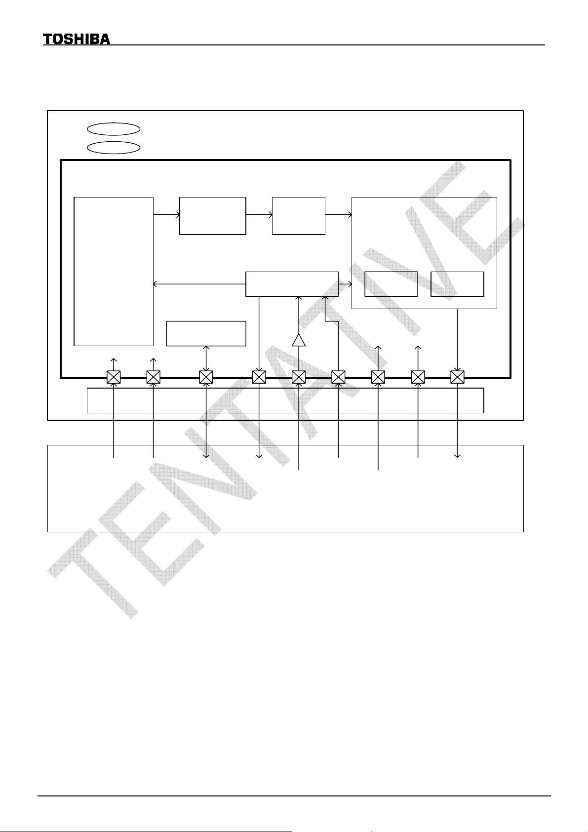
BLOCK DIAGRAM
VGA CMOS Sensor
Image
Area
TCM8230MD (A) Ver. 1.20
Double Lens
CDS / AGC ADC
TCM8230MD
TG / S G
Signal
Processing
AWB ALC
I2C bus I/F
PVDD
IOV DD
(2.8V )
IOVSS
SDA
SCL
Host system
CDS : Correlated Do uble Sampling
AGC : Automatic Gain Control
ADC : Analog to Degital Converter
TG : Timing pulse Generator
SG : Sync pulse Generator
AWB : Auto Whi te Balance
ALC : Auto Luminance Control
Connecting terminals
HD
VD
EXTCLK
RESET
DVDD
(1.5V)
DVSS
AVSS
DOUT0
to
DOUT7
DCLK
04/01/05 3/27
Page 4
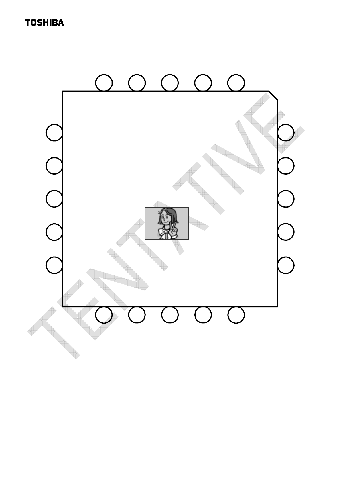
PIN LAYOUT
TCM8230MD (A) Ver. 1.20
6
7
8
9
DVDD
DVSS
VD
HD
5
SDA
SCL
RESET
EXTCLK
TCM8230MD
TOP (Lens si de) vi ew
Orientation
1234
PVDD
DOUT7
DOUT6
DOUT5
DOUT4
20
19
18
17
10
DCLK
11
DOUT0
DOUT1
DOUT2
DOUT3
141312
15
IOVDD
IOVSS
16
04/01/05 4/27
Page 5
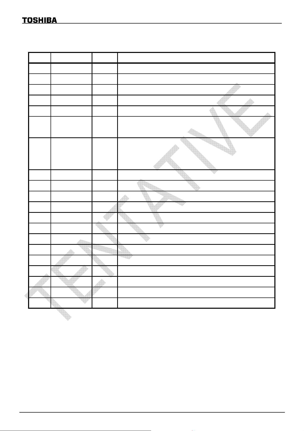
PIN FUNCTIONS
TCM8230MD (A) Ver. 1.20
No. NAME I/O FUNCTION
1 PVDD - VDD for sensor (photo diode) ( 2.8V )
2 EXTCLK I Clock for external input
3 RESET I RESET terminal ("L" active)
4SCL I
5SDAI/O
Clock for I
Data for I
2
C-bus command
2
C-bus command
6DVDD -
VDD for digital circuits, (1.5V )
VDD for sensor (A/D converter) (1.5V )
GND for digital circuits
-DVSS7
GND for sensor (A/D converter)
GND for sensor (photo diode)
8 VD O Vertical syncronization pulse output
9 HD O Holizontal syncronization pulse output
10 DCLK O Clock for output data
11 DOUT0 O Data output (LSB)
12 DOUT1 O Data output
13 DOUT2 O Data output
14 DOUT3 O Data output
15 IOV SS - GND for I/O
16 IOVDD - VDD for I/O ( 2.8V )
17 DOUT4 O Data output
18 DOUT5 O Data output
19 DOUT6 O Data output
20 DOUT7 O Data output (MSB)
04/01/05 5/27
Page 6
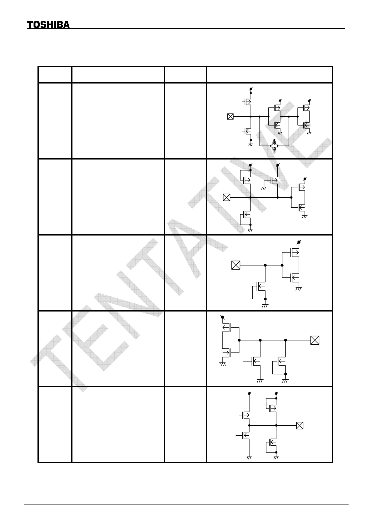
INTERFACE CIRCUITS
TCM8230MD (A) Ver. 1.20
PIN No.
2
3
NAME I/O INTERFACE CIRCUIT
IOVDD
IOVDD IOVDD
EXTCLK I
GND
IOVDD
GND
IOVDD IOVDD
GND
IOVDD
RESET
("L" active)
GND
I
GND
GND
IOVDD
GND
4
5
8-14,
17-20
SCL I
SDA I/O
DOUT0 to DOUT7,
HD, VD, DCLK
GND
GND
IOVDD
GND
GND GND
IOVDD IOVDD
O
GND GND
04/01/05 6/27
Page 7
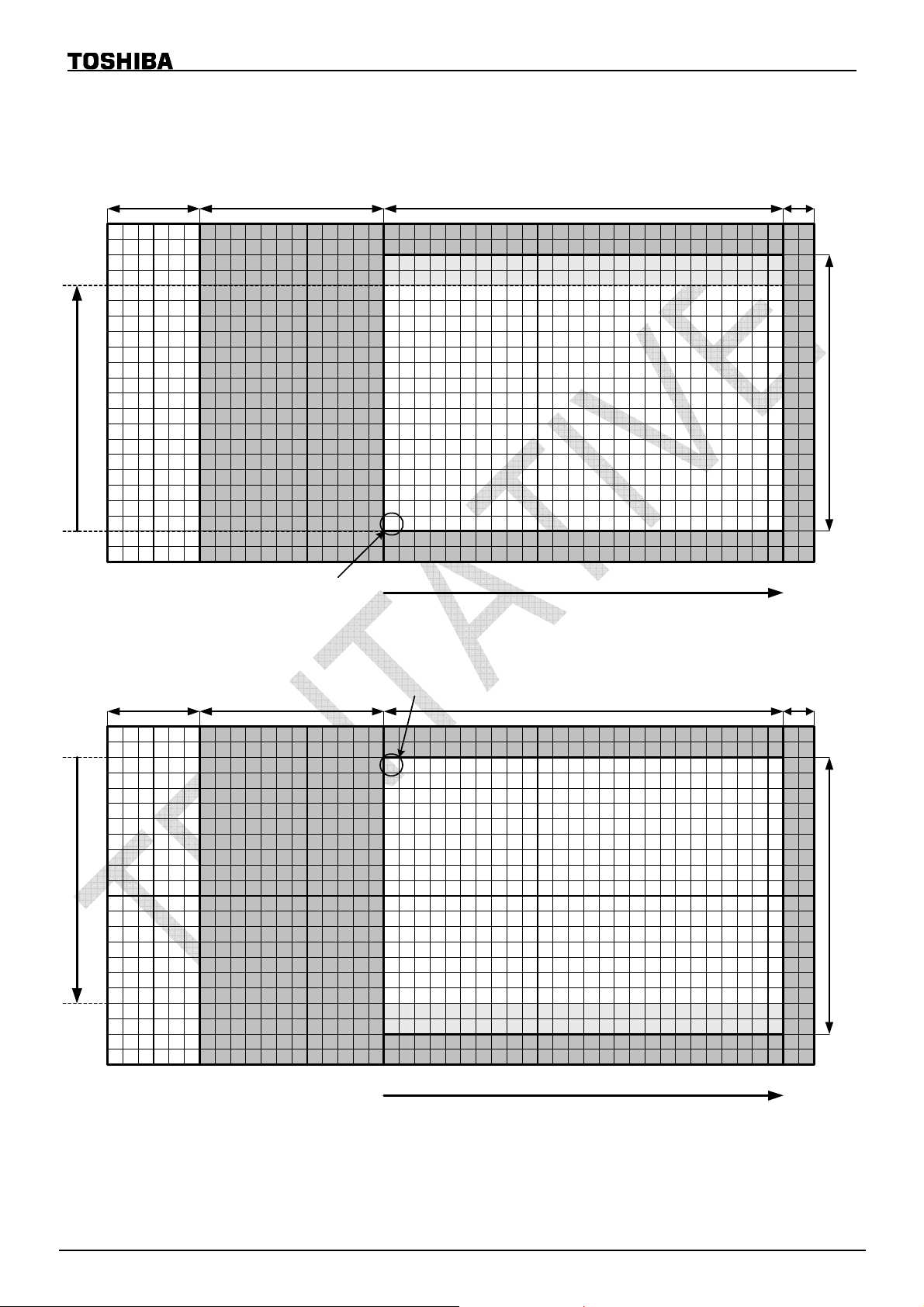
PIXEL ARRANGEMENT
1. V_INV=0
Dummypixels OB44pixels Signalpixels 660pixels
492
491
490
489
488
487
Vertical
6
5
4
3
2
1
TCM8230MD (A) Ver. 1.20
Lightshieldedpi xel s
2pixels
B G
B G
B G
B G
r
B G
r
B G
r
B G
r
b
b
RG
RG
r
r
B G
B G
b
b
RG
RG
r
r
B G
B G
b
b
RG
RG
r
r
B G
B G
b
b
RG
RG
r
r
B G
b
b
RG
B G
b
RG
B G
b
RG
B G
b
RG
b
RG
RG
r
r
B G
b
b
RG
RG
r
r
B G
b
b
RG
RG
r
r
B G
b
b
RG
RG
r
r
B G
r
B G
r
B G
r
B G
r
B G
B G
B G
b
b
RG
RG
r
r
B G
B G
b
b
RG
RG
r
r
B G
b
b
RG
B G
b
RG
b
RG
RG
r
r
B G
b
b
RG
RG
r
r
Signalpixels 494pixels
B G
B G
B G
b
b
RG
RG
r
r
B G
B G
b
b
RG
RG
r
r
B G
b
b
RG
B G
b
RG
b
RG
RG
r
r
B G
b
b
RG
RG
r
r
OB: Optical Black R: Red pixels Gr,Gb: Green pixels B: Blue pixels
2. V_INV =1 (Vertical flip mode)
Dummypixels OB44pixels Signalpixels 660pixels
1
2
3
4
5
6
Vertical
487
488
489
490
491
492
12345
Startpixel
B G
B G
b
RG
RG
r
r
B G
B G
b
RG
RG
r
r
B G
B G
b
RG
RG
r
r
B G
B G
b
RG
RG
r
r
6
HorizontalStartpixel
655
656
657
658
659
660
Lightshieldedpi xel s
2pixels
B G
B G
b
r
B G
b
r
B G
b
r
B G
b
r
B G
b
b
RG
B G
b
RG
B G
b
RG
B G
b
RG
b
RG
RG
r
r
B G
b
b
RG
RG
r
r
B G
b
b
RG
RG
r
r
B G
b
b
RG
RG
r
r
B G
r
B G
r
B G
r
B G
r
B G
B G
B G
b
b
RG
RG
r
r
B G
B G
b
b
RG
RG
r
r
B G
b
b
RG
B G
b
RG
b
RG
RG
r
r
B G
b
b
RG
RG
r
r
Signalpixels 494pixels
B G
B G
B G
b
b
RG
RG
r
r
B G
B G
b
b
RG
RG
r
r
B G
b
b
RG
B G
b
RG
b
RG
RG
r
r
B G
b
b
RG
RG
r
r
12345
6
Horizontal
655
656
657
658
659
660
OB: Optical Black R: Red pixels Gr,Gb: Green pixels B: Blue pixels
04/01/05 7/27
Page 8
TCM8230MD (A) Ver. 1.20
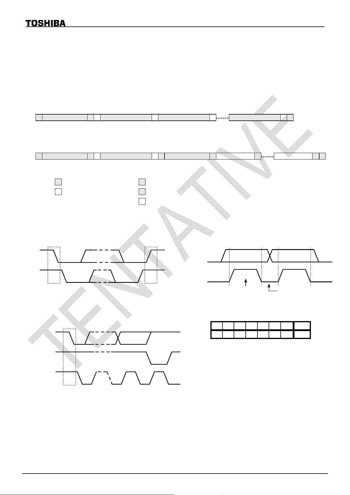
CONTROL I/F
TCM8230MD(A) control interface configuration is based on fast mode I2C bus.
Register setting can be changed via I
All register settings are able to read via I
2
C bus.
2
C bus.
Write mode
Slave AddressS 0 A Sub Address A Data 1 Data n A P
MSB 7bit 8bit 8bit 8bit
A
Read mode
Slave AddressS 0 A Sub Address A Data 1 Data n A P
MSB 7bit 8bit 8bit 8bit
: Host Command
: TCM8230MD(A)
S
P
A
Slave AddressS 1
MSB 7bit
: Start condition
: End condition
: Acknowledge
A
Start condition, End condition Bit Transfer
SDA
SDA
SCL
SP
Startcondition Endconditon
SCL
datalinestable;
datavalid
changeofdataallowed
Acknowledge Slave address
SDA
fromtrancemitter
SDA
from reciver
* TCM8230MD(A) use 7bit Slave address
HiZ
HiZ
A6 A5 A4 A3 A2 A1 A0 R/W
01111001/0
SCL
from master
S
189
Purchase of TOSHIBA I2C components conveys a license under the Philips I2C Patent Rights to use these
components in an I
defined by Philips.
2
C system, provided that the system conforms to the I2C Standard Specification as
04/01/05 8/27
Page 9
LENSRPO
g
TCM8230MD (A) Ver. 1.20
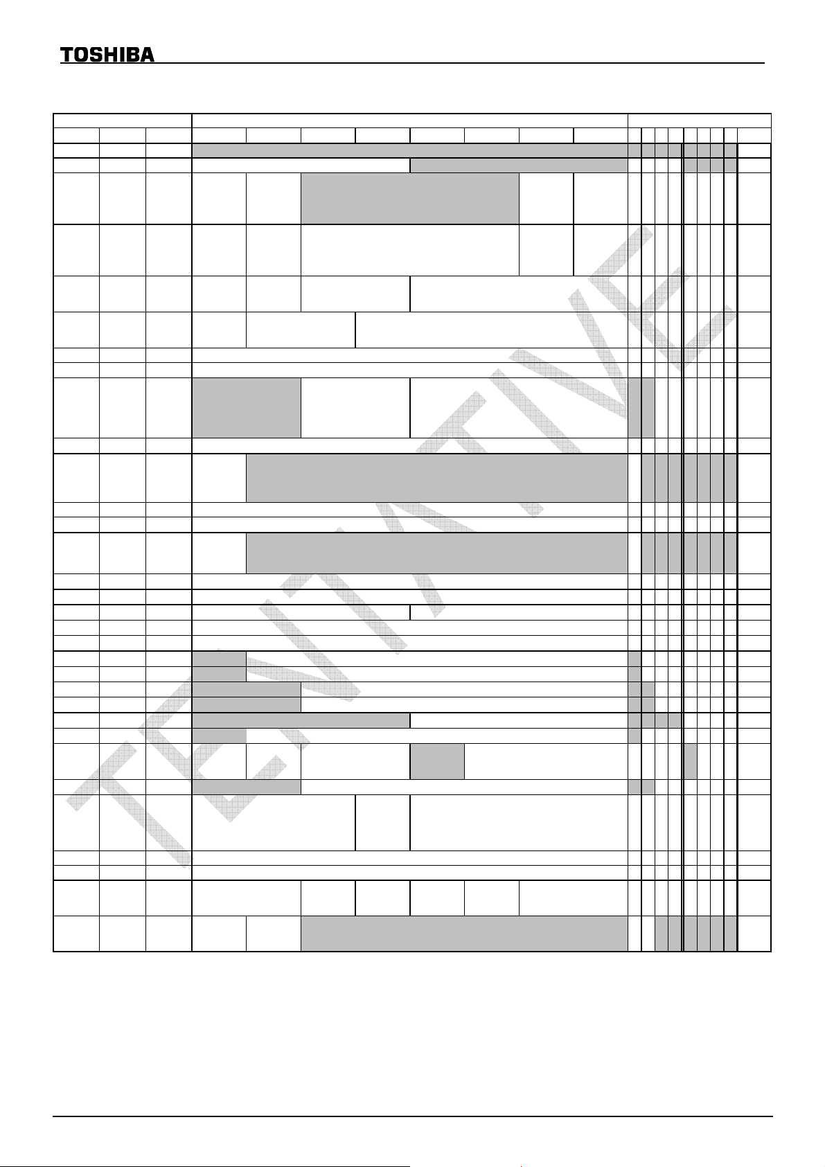
INTERNAL REGISTER
ADDRESS fast last
DEC BIN HEX
BIT7(MSB) BIT6 BIT5 BIT4 BIT3 BIT2 BIT1 BIT0(LSB)
0 0000000000 01110000
1 0000000101 0001 0000
2 0000001002
3 0000001103
4 0000010004
5 0000010105
6 0000011006
7 0000011107 11
8 0000100008
9 0000100109
Test Mode
FPS
0:30fps
1:15fps
DOUTSW
0:ON
1:0FF
V_INV
0:normal
1:invert
ALCSW
0:AUTO
1:MANUAL
ESRSPD
[7:0]
AG
[7:0]
ALCL
ACF
0:50Hz
1:60Hz
DATAH Z
0:OUT
1:Hi-Z
H_INV
0:normal
1:invert
ESRLIM
[7:0]
0h:VGA 1h:QVGA(f) 2h:QVGA(z)
[3:0]
PICSIZ
3h:QQVGA(f) 4h:QQVGA(z) 5h:CIF(f)
6h:QCIF(f) 7h:QCIF(z) 8h:subQCIF(f)
9h:subQCIF(z)
ESRLSW[1:0]
0h : Short 1h :
2h & 3h :
Lon
[1:0]
ALCMODE
0h:Centaer Wei ght
1h:Average
2h:Center only
3h:Backlight
ESRSPD
[1:0]
V_LENGTH
[12:8]
ALCH
[3:0]
[3:0]
DCLKP
0 : normal
1: reverse
PICFMT
0:YUV422
1:RGB565
ACFDET
0 : AUTO
1: MANUAL
CM
0:COLOR
1:B/W
AWBSW
10 000010100A
11 000010110B
12 000011000C
0:AUTO
1:MANUAL
[7:0]
MRG
[7:0]
MBG
GAMSW
13 000011010D
14 000011100E
15 000011110F
16 0001000010
17 0001000111
18 0001001012 0
19 0001001113 0
20 0001010014 00
21 0001010115
22 0001011016
23 0001011117
24 0001100018
25 0001100119
26 000110101A 00100000
0:ON
1:OFF
[7:0]
HDTG
[7:0]
VDTG
HDTCORE
[7:0]
CONT
[7:0]
BRIGHT
MHMODE
0:
1:
[3:0]
[6:0]
VHUE
[6:0]
UHUE
[6:0]
SATU
MHLPFSE
L
0:
1:
VGAIN
UGAIN
YMODE
[5:0]
LENS
[5:0]
[5:0]
[1:0]
VDTCORE
UVCORE
[3:0]
[3:0]
MIXHG
[2:0]
default(ROM data)
B7B6B5 B4 B3B2B1B0
1100 0
10
0
0000 1111
0000 0010
0000 1101
00 0000
0011 1000
0
1000000
0
0000000
0100 0000
0
1000000
000
0010 1111
0000 0100
0010 0010
1001 1010
0001100
0001010
00 1000
0011 1000
0011 1000
0000 0001
0010 0111
00000100
000
00000
00000
HEX
70
10
40
80
0F
02
0D
C0
38
40
00
40
40
00
2F
04
22
9A
0C
0A
08
38
38
01
27
04
20
0:Gain
27 000110111B
28 000111001C
29 000111011D
30 000111101E
31 000111111F
AGLIM
ES100S
ES120S
D_MASK
SLEEPSW
0:ACTIVE
1:SLEEP
[2:0]
[7:0]
[7:0]
[1:0]
CODESW
0:OFF
1:OUT
SRST
0:OFF
1:reset
L
up
1:Gain
CODESEL
0 : original
1 : ITU656
LENSRGAIN
HSYNCSEL
0 : normal
1 :
[3:0]
TESPIC
0:Not out
1:Out
[1:0]
PICSEL
0h:Colorbar 1h:Ramp1
2h :Ramp2
01000110
1001 1110
1000 0011
01101000
00000000
The registers of gray mesh (unassigned registers) are not defined. Input data of the registers of gray mesh
must input “0”. The registers of testmode must input default data.
04/01/05 9/27
46
9E
83
68
00
Page 10

FSSTBSW
FPSLNKS
TCM8230MD (A) Ver. 1.20
ADDRESS fast last
DEC BIN HEX
32 0010000020 00000000
33 0010000121 00000001
34 0010001022
35 0010001123 01000000
36 0010010024
37 0010010125 01011111
38 0010011026
39 0010011127 00010110
40 0010100028
41 0010100129
42 001010102A 00001000
43 001010112B 00000100
44 001011002C 00000000
45 001011012D 00000000
46 001011102E
47 001011112F
48 0011000030
49 0011000131
50 0011001032 00000000
51 0011001133 00000000
52 0011010034 00000000
53 0011010135 00000000
54 0011011036 00000000
55 0011011137 00000000
56 0011100038 00000000
57 0011100139 10001100
58 001110103A 11001111
59 001110113B 10000000
60 001111003C 00000000
61 001111013D
62 001111103E
63 001111113F 11000000
BIT7(MSB)BIT6BIT5BIT4BIT3BIT2BIT1BIT0(LSB)B7B6B5B4B3B2B1B0 HEX
[7:0]
HNUM
[7:0]
HPPH
[8]
HPPH
[7:0]
HDSPPH
[8]
HDSPPH
[7:0]
HAPRPH
HAPRPH
[8]
[7:0]
HOUTPH
[8]
HOUTPH
0 : NOT
OUT
SCMD[15:8]
SCMD[7:0]
TCSB1L
0:
1:
TCRAMS
0:
1:
TALCDISP
0:
1:
[7:0]
ESROUT
[7:0]
AGOUT
ALCDATA
AWBRYDA
AWBBYDA
AGSLOW1
DETSEL
AGSLOW2
REJHLEV
ALCLOCK
0:
1:
SHESRSW
0:Disable
1:Enable
AGMIN
[7:0]
[3:0]
[7:0]
[7:0]
VRRPH
VDSPPH
VOUTPH
FSSTBPOL
0 : normal
1 : invert
TCPEROSW
TSPCHK
0:
1:
TGAMROM
0:
1:
TALCOSW
ESROUT
[7:0]
[7:0]
[1:0]
[1:0]
W
0:
ESLIMSEL
0:
1:
[6:0]
[6:0]
[6:0]
FSSTBPH[3:0]
FSSTBW[3:0]
SCMD[19:16]
[2:0]
TCPERAGC TALCRST TWBS TWBG
[2:0]
[14:8]
[5:0]
DGOUT
FLLSMODE
DG
ALCSPD[1:0]
SHESRSPD
[1:0]
[5:0]
[1:0] 1 0 0 0 0 1 0 1
TCSBIN
0:
1:
TCSB[3:0]
PBDISP
FLLSLIM
ACDETNC
ALCSTEP[1:0]
ELSTEP
[1:0]
[3:0]
[1:0]
TCRAM
0:
1:
[3:0]
TROM[1:0]
TACDET
[1:0]
TDISP
[1:0]
REJH
ELSTART
[1:0]
[1:0]
00100110
00100111
00000000
00100011
00001000
00000000
00000000
00000000
00000000
00010111
default
00
01
26
40
27
5F
00
16
23
08
08
04
00
00
00
00
00
00
00
00
00
00
00
00
00
8C
CF
80
00
17
85
C0
The registers of gray mesh (unassigned registers) are not defined. Input data of the registers of gray mesh must
input “0”. The registers of testmode must input default data.
04/01/05 10/27
Page 11

AWBCSPO
TCM8230MD (A) Ver. 1.20
ADDRESS fast last
DEC BIN HEX
0100000
64
0
65 0100000141
66 0100001042 0
67 0100001143 0
68 0100010044 0
69 0100010145 0
BIT7(MSB)BIT6BIT5BIT4BIT3BIT2BIT1BIT0(LSB)B7B6B5B4B3B2B1B0 HEX
40
LI1POL
0:
1:
JAMP
0:
1:
CS1POL
0:
1:
JAMG
[6:0]
LI3POL
0:
1:
PREGRG
PREGBG
PRERG
PREBG
CS3POL
0:
1:
[5:0]
[5:0]
[5:0]
[5:0]
DINCKSW
0:
1:
default
000000
00000000
0000000
0000000
0010101
0011111
00
00
00
00
00
15
1F
70 0100011046
[6:0]
0:
[7:0]
[7:0]
[7:0]
[7:0]
[7:0]
[7:0]
[7:0]
MSKBR
[6:0]
MSKGR
[6:0]
MSKRB
[6:0]
MSKGB
[6:0]
MSKRG
[6:0]
MSKBG
VDTCSW
0:
1:
VDTPSW
0:
1:
CS12POL
0:
1:
[6:0]
UVSKNC
[6:0]
UVLJ
WBDIVCLP
0:
1:
DTCYLV
DTCGAIN
YLCUTL
YLCUTH
WBNOLJ
ALLAREA
0:
1:
KIZUSW
0:OFF
1:ON
[5:0]
[5:0]
DTLLIMSW
0:
1:
[5:0]
[5:0]
[1:0]
WBLOCK
0:
1:
PBRDSW
DTLYLIM
WBNOLJS
0:
C
1:
[3:0]
WB2SP
[3:0]
WB2IM1
0:
1:
WBDIVSC
WBSPDUP
[2:0]
ABCSW
[1:0]
[1:0]
71 0100011147
72 0100100048
73 0100100149
74 010010104A
75 010010114B
76 010011004C
HDTCSW
77 010011014D
78 010011104E
79 010011114F
80 0101000050
81 0101000151
0:
1:
HDTPSW
0:
1:
LI12POL
0:
1:
YLCUTLMS
0:
K
1:
YLCUTHM
SK
1:
82 0101001052 0
83 0101001153 0
84 0101010054 001
85 0101010155 01
86 0101011056
WBGMIN
WBGMAX
LE
0:
87 0101011157 0000
88 0101100058
89 0101100159
90 010110105A
91 010110115B
92 010111005C
93 010111015D 00
94 010111105E 000010
PBDLV
PBC1LV
PBC2LV
PBC3LV
PBC4LV
00000000
01000100
01000100
0
00000
01
01000101
01100110
00110000
1100000
1
0100000
0
0001001
0
0000111
0
0101111
0
0000010
0000000
01011
100000
000000
01
0110
100010
0
0
00100
00001000
00000100
0
0001
001000
0
000
The registers of gray mesh (unassigned registers) are not defined. Input data of the registers of gray mesh
must input “0”. The registers of testmode must input default data.
11
00
00
44
44
20
45
66
30
E0
20
09
07
2F
02
00
2B
60
40
06
22
23
08
04
08
08
08
04/01/05 11/27
Page 12

TCM8230MD (A) Ver. 1.20
OUTLINE OF INTERNAL REGISTER
* Frame rate setting (30fps, 15fps )
* Picture size setting of digital output ( VGA, QVGA, QQVGA, CIF, QCIF, subQCIF )
* Selection of digital data output format (8bit YUV422, RGB565)
* Sync. code setting ( ON/OFF, 2 mode )
* Color signal adjustment ( Masking, color axis correction, saturation, etc. )
* Luminance signal adjustment ( Contrast, Brightness, Gamma, H,V edge enhancement )
* ALC ON/OFF
* ALC mode setting ( area selection, speed selection, flicker reduction mode setting )
* AWB ON/OFF
* Vertical and Horizontal flip
* Sleep mode setting
* Some kinds of correction setting ( Lens shading correction etc. )
8bit parallel image data
YUVmode RGBmode
1st 2nd 3rd 4th 1st 2nd
DOUT0 U0(n) Y0(n) V0(n) Y0(n+1) B0 G3
DOUT1 U1(n) Y1(n) V1(n) Y1(n+1) B1 G4
DOUT2 U2(n) Y2(n) V2(n) Y2(n+1) B2 G5
DOUT3 U3(n) Y3(n) V3(n) Y3(n+1) B3 R 0
DOUT4 U4(n) Y4(n) V4(n) Y4(n+1) B4 R 1
DOUT5 U5(n) Y5(n) V5(n) Y5(n+1) G0 R2
DOUT6 U6(n) Y6(n) V6(n) Y6(n+1) G1 R3
DOUT7 U7(n) Y7(n) V7(n) Y7(n+1) G2 R4
Image size format
Imagesize Displaymode
VGA Full 640 480 (1,1) (640,480) 1 Normal -
Full (1,1) (639,479) 1/2 Lowpower Sub-samplingfromVGA
Zoomx2 (161,121) (480,360) 1 Normal WindowingfromVGA
QQVGA
CIF Full 352 288 (21,1) (608,478) 1 Normal 3/5filteringfromVGA
QCIF
subQCIF
QVGA(f)meansQVGAfull.
QQVGA(f)meansQVGAfull.
Full (1,1) (637,477) Sub-samplingfromQVGA(f)
Zoomx2 (161,121) (479,359) Sub-samplingfromVGA
Full (21,1) (608,478) 1/2 Lowpower 3/5filteringfromQVGA(f)
Zoomx2 (173,121) (466,360) 1 Normal WindowingfromCIF
Full (1,1) (636,476) 4/5filteringfromQQVGA(f)
Zoomx2 (161,121) (479,359)
Pixels
perH
320QVGA
160 1/2 Lowpower
176
Effective
Hlines
240
120
144
96128 1/2
Startpoint
(H,V)
Endpoint
(H,V)
DCLK
mode
Operation
mode
LowPower
Resizingmethod
1st:3/5filteringfromQVGA(f)
2nd:Sub-samplingfrom"1st"
VGA VideoGraphicsArray
QVGA QuarterVGA
QQVGA QuarterQVGA
CIF CommonIntermediateFormat
QCIF QuarterCIF
04/01/05 12/27
Page 13

TCM8230MD (A) Ver. 1.20
SYNCHRONIZATION CODE
Synchronization code output format
CODESW=1
DCLK
DOUT7
〜
0
FFh
00h 00h Code
CODESW(Address=1Eh, Bit5) is able to add synchronization codes. “Code“ part is changed Mode1 or Mode2
by CODESEL(Address=1Eh, Bit4).
Mode1 (Original format, CODESEL=0)
These codes only exists in active lines
Frame
Start
Code Code Code Co de Code Code
Active Line 1
Line
End
Line
Start
Active L ine 2
Line
End
Line
Start
Active Line 480
(VGA)
Frame
End
Code Picture Code
Blanking
Blanking
02 01
00
00
00
00
00
Line 1
Line 2
Line 3
Line 4
Line 480 (VGA)
Line 240 (QVGA)
Line 120 (QQVGA)
Line 288 (CIF)
Line 144 (QCIF)
Line 96 (subQCIF)
01
01
01
01
03
Blanking
Blanking
640 pixels (VGA)
320 pixels (QVGA)
160 pixels (QQVGA)
352 pixels (CIF)
176 pixels (QCIF)
128 pixels (subQCIF)
Line start code : FFh 00h 00h 00h
Line end code : FFh 00h 00h 01h
Frame start code : FFh 00h 00h 02h
Frame end code : FFh 00h 00h 03h
04/01/05 13/27
Page 14

TCM8230MD (A) Ver. 1.20
Mode2 (ITU656 format, CODESEL=1)
These codes exists in every lines
1 0 V H 0 0 00Code
V : 1:Blanking 0:Active Line
H : 1:End of Active Pixel 0:Start of Active Pixel
Code Picture Code
BlankingA0
A0
80 90
80
80
80
80
80
A0
A0
Blanki ng and start active pixel code : FFh 00h 00h A0h
Blanki ng and endactive pixel code : FFh 00h 00h B0h
Active line and start active pixel code : FFh 00h 00h 80h
Active line and end ac tive pixel code : FFh 00h 00h 90h
Blanking
Line 1
Line 2
Line 3
Line 4
Line 480 (VGA)
Line 240 (QVGA)
Line 120 (QQVG A)
Line 288 (CIF)
Line 144 (QCIF)
Line 96 (subQCIF)
Blanking
Blanking
640 pixels (VGA)
320 pixels (QVGA)
160 pixels (QQVGA)
352 pixels (CIF)
176 pixels (QCIF)
128 pixels (subQCIF)
B0
B0
90
90
90
90
90
B0
B0
04/01/05 14/27
Page 15

TCM8230MD (A) Ver. 1.20
DATA OUTPUT TIMING CHART
TCM8230MD supports 2 HD pulses, one is “Blanking pulse”, and another one is “Normal pulse”.
You can choose HD pulse by HSYNCSEL (Address=1Eh Bit3).
Pixel Size mode (HD=Blanking pulse)
1. Vertical timing (HSYNCSEL=1)
Normal operation mode
(VGA, CIF(full), QVGA(zoom), QCIF(zoom))
1 frame
VD
507 lines
18 lines
VGA
HD
full
CIF
full
QVGA
zoom
QCIF
zoom
123
12 3 287
12
3
45
45
3
67
45
6
45 6
6
7
7
23812
143
7
143
286
239 240
144
Low power operation mode
(QVGA(full), QQVGA(full), QQVGA(zoom), QCIF(full), subQCIF(full), subQCIF(zoom))
1 frame
VD
QVGA
HD
full
QCIF
full
QQVGA
full
1
23
12
45
3
67
412 3 5
4
254 lines
238 239
142 143 144
119 120
478
479 480
288
240
12
12
12
12
9 lines
1
1
1
QQVGA
zoom
subQCIF
full
subQCIF
zoom
12
1
12
4
3
2
34
56
3
56
7
4
120119
96
96
04/01/05 15/27
1
1
1
Page 16

TCM8230MD (A) Ver. 1.20
2. Horizontal timing (HSYNCSEL=1)
Normal operation mode
(VGA, CIF (full), QVGA (zoom), QCIF (zoom))
DCLK
(DCLKP=0)
VD
156.5 cycles
of DCLK
VGA
full
HD
Data
blanking
2 31
1280 cycles of DCLK (640 PIXEL)
1 line
280 cycles of DCLK
638
639 640
blanking
2 31
4
CIF
full
QVGA
zoom
QCIF
zoom
Data
Data
Data
blanking
blanking
blanking
704 cycles of DCLK (352 PIXEL)
2 31
640 cycles of DCLK (320 PIXEL)
231
352 cycles of DCLK
(176 PIXEL)
231
174HD175 176
350HD351 352
318HD319 320
1208 cycles of DCLK
856 cycles of DCLK
blanking
920 cycles of DCLK
blanking
blanking
Blanking Y=0x00, UV=0x80
HNUM=0
Low power operation mode
(QVGA(full), QQVGA(full), QQVGA(zoom), QCIF(full), subQCIF(full), subQCIF(zoom))
DCLK
(DCLKP=0)
VD
156.5 cycles
QVGA
full
QCIF
full
QQVGA
full/zoom
subQCIF
full/zoom
HD
Data
HD
Data
HD
Data
HD
Data
of DCLK
blanking
blanking
blanking
blanking
640 cycles of DCLK (320 PIXEL)
1
223 4 318 319 320
352 cycles of DCLK (176 PIXEL)
1
320 cycles of DCLK
(160 PIXEL)
1
256 cycles of DCLK
(128 PIXEL)
1
159
128
175 176
160
1 line
920 cycles of DCLK
1208 cycles of DCLK
1240 cycles of DCLK
blanking 1 2 3
1304 cycles of DCLK
blanking 1 2 3
2 31
4
2 31
4
2 31
4
1blanking 2 3
1 2 3blanking
Blanking Y=0x00, UV=0x80
04/01/05 16/27
Page 17

TCM8230MD (A) Ver. 1.20
Pixel Size mode (HD=Normal pulse)
1. Vertical timing (HSYNCSEL=0)
Normal operation mode
(VGA, CIF(full), QVGA(zoom), QCIF(zoom))
VD
1 frame
18 lines
507 lines
VGA
HD
full
CIF
full
QVGA
zoom
QCIF
zoom
12
2
1
12
1
2
45
3
3
456
3
3
67
45
45 6 7
6
7
7
143
143
238
239240
144
286
287
Low power operation mode
(QVGA(full), QQVGA(full), QQVGA(zoom), QCIF(full), subQCIF(full), subQCIF(zoom))
1 frame
VD
QVGA
HD
full
QCIF
full
QQVGA
full
123
45
12
3
67
412 3 5
4
254 lines
238 239 240
142 143 144
119 120
478
479480
288
9 lines
1
2
12
12
12
1
1
1
QQVGA
zoom
subQCIF
full
subQCIF
zoom
12
12 43
12
3
4567
34
56
120119
96
96
04/01/05 17/27
1
1
1
Page 18

TCM8230MD (A) Ver. 1.20
2. Horizontal timing (HSYNCSEL=0)
Normal operation mode
(VGA, CIF (full), QVGA (zoom), QCIF (zoom))
DCLK
(DCLKP=0)
VGA
full
CIF
full
QVGA
zoom
QCIF
zoom
VD
HD
DOUT
DOUT
DOUT
DOUT
156.5 cycles
of DCLK
156 cycles of
DCLK
blanking
156 cycles of
DCLK
blanking
156 cycles of
DCLK
blanking
156 cycles of
DCLK
blanking
1 line
1404 cycles of DCLK
638
2 31
639 640
1404 cycles of DCLK
2 31
350HD351 352
blanking
1404 cycles of DCLK
2 31
318HD319 320
blanking
1404 cycles of DCLK
2 31
174HD175 176
blanking
Blanking Y=0x00, UV=0x80
HNUM=0
Low power operation mode
(QVGA(full), QQVGA(full), QQVGA(zoom), QCIF(full), subQCIF(full), subQCIF(zoom))
DCLK
(DCLKP=0)
156 cycles of
blanking
156 cycles of
156 cycles of
156 cycles of
DCLK
DCLK
DCLK
DCLK
2 31
4
2 31
4
2 31
4
2 31
4
VD
156.5 cycles
QVGA
full
QCIF
full
QQVGA
full/zoom
subQCIF
full/zoom
HD
DOUT
HD
DOUT
HD
DOUT
HD
DOUT
of DCLK
156 cycles of
DCLK
blanking
156 cycles of
DCLK
blanking
156 cycles of
DCLK
blanking
156 cycles of
DCLK
blanking
1
223 4 318 319 320
1
1
1
159
128
175 176
160
1404 cycles of DCLK
1404 cycles of DCLK
1404 cycles of DCLK
1404 cycles of DCLK
1 line
156 cycles of
DCLK
156 cycles of
DCLK
156 cycles of
DCLK
blanking 1 2 3
156 cycles of
DCLK
blanking 1 2 3
1blanking 2 3
1 2 3blanking
Blanking Y=0x00, UV=0x80
HNUM=0
04/01/05 18/27
Page 19

TCM8230MD (A) Ver. 1.20
Exposure mode
TCM8230MD supports long exposure time mode (ESRLSW (Address=04h, Bit5,4)= 1) and extra-long exposure time
mode (ESRLSW (Address=04h Bit5,4)= 2, 3).
Vertical timing
Normal mode
ESRLSW=0
VD
Data
1st frame
2nd frame 3rd frame
Long exp.
mode
ESRLSW=1
Extra-long
exp. mode
ESRLSW=2,3
V_LENGTH=3
VD
Data
VD
Data
blanking blanking blanking
blanking blanking blanking blanking
1st frame 2nd frame 3rd frame
When use these modes, you should be sent below I
ESRLSW (Address=04h Bit5,4)= 1, 2 or 3
Address=22h, Data=10h (Default Data=26h)
Address=24h, Data=0Fh (Default Data=27h)
Address=28h, Data=06h (Default Data=23h)
2nd frame1st frame
2
C commands before entry these modes.
04/01/05 19/27
Page 20

TCM8230MD (A) Ver. 1.20
POWER ON SEQUENCE
EXTCLK
(V
= 2.8V)
p-p
DVDD
(1.5V)
PVDD
(2.8V)
IOVD D
(2.8V)
RESET
(from O u tside)
SCL/SDA
VD
100ms>x>=0ns
100ms>x>=0ns
>0ns
>=100 cycles of EXTCLK
>=2000 cycles of EXTCLK
Commands are available
*
> 1V
DOUT
((VOUTPH + 3) - VRRPH) + 4
*
In default case: VOUTPH=35dec, VR R P H = 38de c, ((35 + 3) - 38) + 4 = 4H
D_MASK=1
x
TCM8230MD cannot output pictures after power on immediately. You should be sent some I
after power on as below.
Address=03h, Data=00h (Default Data=80h)
POWER OFF SEQUENCE
EXTCLK
(V
= 2.8V)
p-p
IOV DD
(2.8V)
100ms>x>0ns
PVDD
(2.8V)
1st picture 2nd picture
2
C commands
DVDD
100ms>x>=0ns
(1.5V)
100ms>x>=0ns
04/01/05 20/27
Page 21

TCM8230MD (A) Ver. 1.20
SLEEP MODE SEQUENCE
1. From normal operation to sleep mode
2 frames
VD
*
SCL/SDA
DOUT
Operation
Mode
EXTCLK
Normal operation
((VOUTPH + 3) - VRRPH) + 4
*
In default case: VOUTPH=35dec, VRRPH=38dec, ((35 + 3) - 38) + 4 = 4H
Sleep Command
Picture
Sleep mode
2. From sleep mode to normal operation
VD
SCL/SDA
DOUT
Operation
Mode
EXTCLK
D_MASK=1
Some registers data, AWB calculated data and ALC calculated data are kept the last values during sleep mode.
1frame
Wake up Command
Sleep mode
3H
> 1 frame
x
Picture
Normal operation
04/01/05 21/27
Page 22

MAXIMUM RATING
Power supply voltage -0.3 to 3.0 -0.3 to 3.6 V
TCM8230MD (A) Ver. 1.20
RATING
1.5V 2.8V UNITS
Storage tempature -30 to 85 Degree C
RECOMMENDED OPERATING CONDITION
MIN TYP MAX UNITS
Power supply
IOVDD, PVDD*
voltage
Operational tempature
DVDD
2.6 2.8 3.0
2.3 2.5 2.7
1.4 1.5 1.6
-20 - 60 Degree C
*If using 2.5V, must input setting command. (Default setting is 2.8V.)
V
04/01/05 22/27
Page 23

TCM8230MD (A) Ver. 1.20
ELECTRICAL CHARACTERISTICS
DC Characteristic ( Ta=25 degree C, DVDD(=AVDD) =1.5V, PVDD= IOVDD =2.8V )
1. POWER
ITEM CONDITION MIN TYP MAX UNITS
VGA(15fps) (Normal operation mode) - 40 TBD mA POWER
Sleep mode - - TBD uA
* Measurement condition : Machbeth chart (full)
*Peak current = 180mA
2. EXTCLK
ITEM
LOW level input voltage
Rectangular
shape
1) Duty referred to 50% level of input EXTCLK
HIGH level input voltage
LOW level input current
HIGH level input current
DUTY - - 45/55 50/50 55/45 % *1
3. SCL and SDA
ITEM
SCL
LOW le vel input voltage
HIGH level input voltage
LOW le vel input voltage
SDA
HIGH level input voltage
LOW level output voltage (IOL=4mA)
4. DOUT0 to DOUT7, DCLK, HD and VD
ITEM
DOUT0 to DO UT7,
DCLK, HD and VD
LOW level output voltage (IOL=2mA)
HIGH level output voltage (IOH=-2mA)
5. RESET
ITEM SYMBOL CONDITION MIN TYP MAX UNIT NOTES
LOW level input volta ge
HIGH level input voltage
LOW level input current
HIGH level input current
V
IL;RESET
V
IH;RESET
I
IL;RESET
I
IH;RESET
SYMBOL CONDITION MIN TYP MAX UNITS NOTES
V
IL;EXTCLK
V
IH;EXTCLK
I
IL;EXTCLK
I
IH;EXTCLK
- -0.3 - IOVDD*0.2 V
- IOVDD*0.8 IOVDD 3.0 V
VIN=GND
VIN=IOVDD
-10 - 10 uA
-10 - 10 uA
SYMBOL MIN TYP MAX UNIT NOTES
V
IL;SCL
V
IH;SCL
V
IL;SDA
V
IH;SDA
V
OL;SDA
0.0 - 0.4 V
IOVDD*0.7 IOVDD 3.0 V
0.0 - 0.4 V
IOVDD*0.7 IOVDD 3.0 V
0.0 - 0.4 V
SYMBOL MIN TYP MAX UNIT NOTES
V
OL;DATA
V
OH;DATA
0.0 - 0.4 V
2.4 IOVDD - V
- -0.3 - IOVDD*0.2 V
-IOVDD*0.8IOVDD 3.0 V
VIN=GND
VIN=IOVDD
-10 - 10 uA
-10 - 10 uA
04/01/05 23/27
Page 24

TCM8230MD (A) Ver. 1.20
AC Characteristic ( Ta=25 degree C, DVDD(=AVDD) =1.5V, PVDD= IOVDD =2.8V )
1. EXTCLK
ITEM SYMBOL FPS MIN TYP MAX UNITS NOTES
Clock frequency
Rise time
Fall time
1) FPS : Address=02h, Bit7
2) All values referred to V
IHmin
f
EXTCLK
t
r;EXTCLK
t
f;EXTCLK
and V
0 25.00
1 27.00
---5ns
---5ns
levels
ILmax
f
EXTCLK
V
IH
V
IL
*111.90 24.54 MHz
*2
2. EXTCLK input circuit
T
r;EXTCLK
2.8V
0V
Duty50:50
T
f;EXTCLK
EXTCLK
TCM8230MD
04/01/05 24/27
Page 25

p
3. SCL and SDA
SCL
SDA
Hold time(repeated) START condition
After this
Setup time for a repeated START condition
Setup time for STOP condition
Width of spike pulse
TCM8230MD (A) Ver. 1.20
ITEM
Clock frequency
Low period
High period
Rise time
Fall time
Rise time
Fall time
eriod, the first clock pulse is
Data hold time
Data setup time
Normal
Wake-up from sleep mode
SYMBOL MIN MAX UNITS NOTES
f
SCL
t
LOW;SCL
t
HIGH;SCL
t
r;SCL
t
f;SCL
t
r;SDA
t
f;SDA
t
HD;STA
t
SU;STA
t
HD;DAT
t
SU;DAT
t
SU;STO
t
SP1
t
SP2
- 400 KHz
1.3 - us
0.6 - us
- 300 ns
- 300 ns
- 300 ns
- 300 ns
0.6 - us
0.6 - us
0-ns
100 - ns
0.6 - us
050ns
020ns
*1
1) All values referred to V
SDA
t
f
SCL
t
LOW
t
HD;STA
and V
IHmin
t
HD;DAT
t
SU;DAT
t
r
ILmax
levels
t
HIGH
t
BUF
t
f
t
SU;STA
t
HD;STA
t
SP
t
SU;STO
RE-STARTSTART
t
r
STOP START
04/01/05 25/27
Page 26

TCM8230MD (A) Ver. 1.20
4. DOUT0 to DOUT7, DCLK, HD and VD
ITEM
DCLK
DOUT0 to DOUT7,
HD, and VD
Setup time of data
Hold time of data
Rise time
Fall time
Rise time
Fall time
SYMBOL MIN MAX UNITS NOTES
t
r;DCLK
t
f;DCLK
t
r;DATA
t
f;DATA
t
pd;SU
t
pd;HD
-6ns
-6ns
-6ns
-6ns
10 - ns
10 - ns
*1
1) All values referred to V
OHmin
and V
OLmax
DCLK
t
pd;SU
Data
Out
DCLKP=0
CHARACTERISTICS OF LENS
Field of view
ITEM
Optical format
Holizontal 57.4 degree
Vertical 44.5 degree
Diagonal 69.1 degree
F number
TV distotion
Focal length
Focusing area
Manual focusing
Structure
levels
t
f;DCLK
t
pd;HD
VALUE UNITS
1/6 inch
F2.8 -
-0.4 %
TBD mm
TBD cm
Not avairable -
Double lens -
t
r;DATA
, t
f;DATA
t
r;DCLK
V
OH;DCLK
V
OL;DCLK
V
OH;DATA
V
OL;DATA
04/01/05 26/27
Page 27

Appendix 1: Module Drawing
TCM8230MD (A) Ver. 1.20
04/01/05 27/27
 Loading...