

Page 1
®
Rayson’s Bluetooth
Module
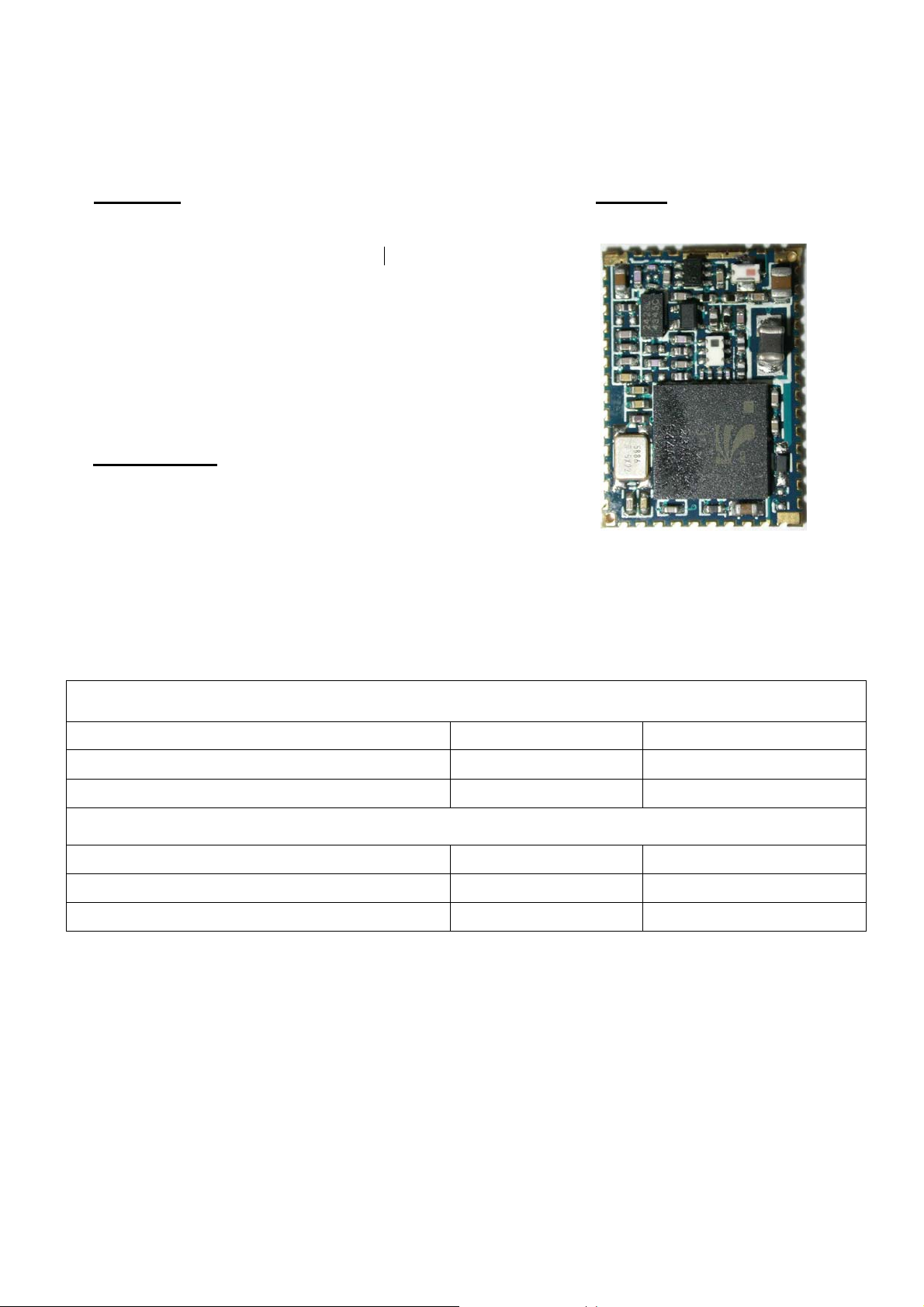
BC03/04-audio Class1 Module BTM-600
Features Outline
The module is a Max.15dBm( Class1 ) module.
Bluetooth standard Ver. 2.0 conformity.
Low current consumption :
Park, Sniff, Hold and Deep Sleep
3.3V and 1.8V operation
Built-in 15-bit Linear Audio Codec
Embedded 6Mbit Flash/ROM Memory
Integrated Switch-mode Regulator
Integrated Battery Charger with programmable current
Interface: USB,UART&PCM(for voice CODEC)
HCI or Headset,Gateway,SPP firmware is available
Small outline. 19.5 x 14 x 2.2 mm
Applications
z Notebook PC,PDA
z Cellular Phone
z Cordless headset
z Domestic and industrial applications
z Headsets
z Automotive hands-free kits
z General purpose Bluetooth system requiring an On-chip CODEC
Electrical Characteristics
Absolute Maximum Ratings
Ratings Min. Max.
Storage Temperature
Supply Voltage VDD -0.4 V 3.7 V
-40 ℃ +150 ℃
Recommended Operating Condition
Operating Condition Min. Max.
Operating Temperature range
Supply Voltage VDD 3.0 V 3.6 V
-20 ℃ +85 ℃
Page 2
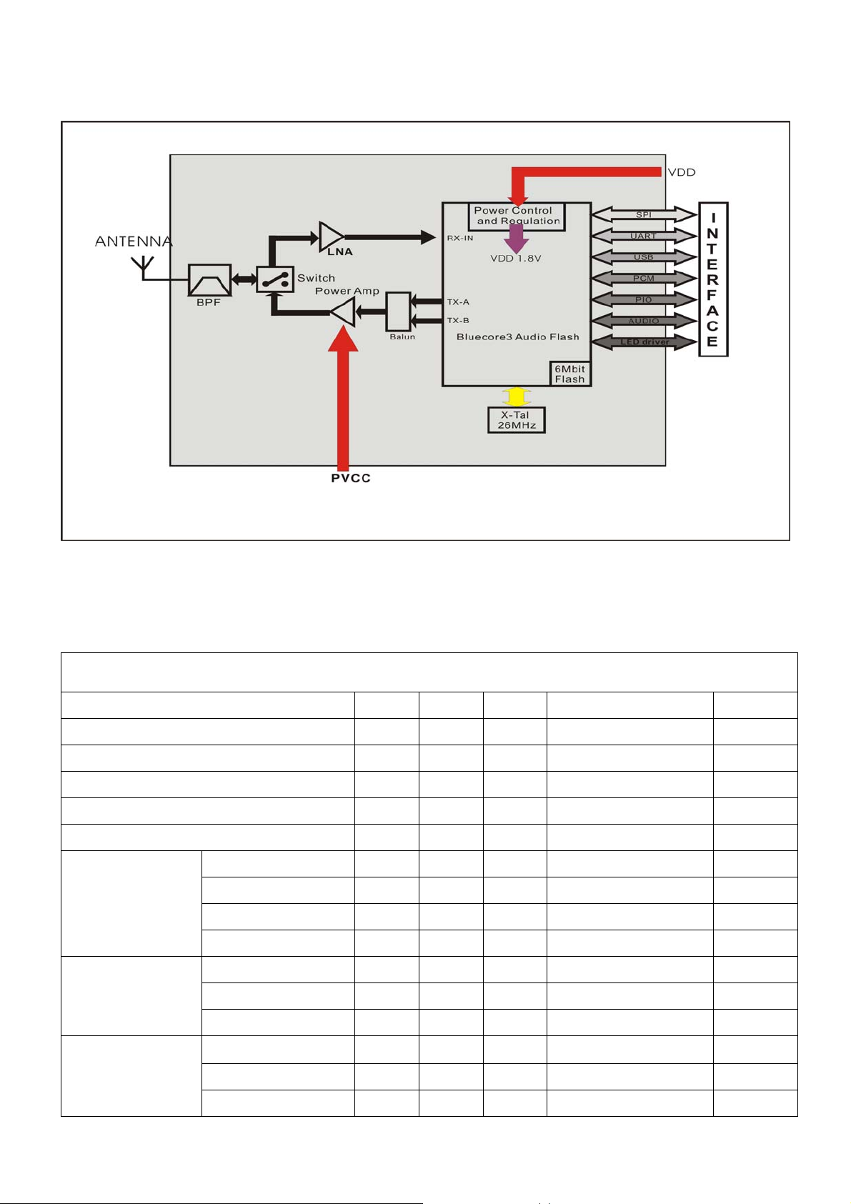
Block Diagram
Radio Characteristics:VDD=1.8V Temperature=+20℃
Transmitter Performance
Parameter Min. Type Max. Bluetooth Spec. Unit
RF transmit power - 13 - -6 to +20 dBm
RF power control range - 35 RF power range control resolution - 0.5 -
20dB bandwidth for modulated carrier - 820 Initial carrier frequency tolerance - 3.0 -
Drift Rate - 8.0 -
Carrier frequency
drift
DH1 - 8.0 DH3 - 9.0 DH5 - 10 -
≥16
≤1000
±75
±20
±24
±40
±40
KHz
KHz
KHz/50uS
KHz
KHz
KHz
Adjacent
characteristic
Modulation
characteristic
+/- 2 MHz - -45 +/- 3 MHz - -48 +/- 4MHz -
△F1avg
△F2avg
△F1avg/△F1avg
- 165 -
- 151 - 115 KHz
- 0.99 -
<-50
≤- 20
≤- 40
140≤△F1avg≤175
≤- 40
≥0.8
dBm
dBm
dBm
KHz
Page 3

Receiver Performance
Parameter Frequency
Min. Type Max. Bluetooth Spec. Unit
(GHz)
Sensitivity at 0.1% BER
for all packet types
Maximum receive signal at 0.1% BER -20
C/I performance
Adjacent channel
sensitivity
Max. level of intermodulation interferers - -27 -
Spurious output level -
2402 - -85 - dBm
2441 - -85 - dBm
2480 - -85 -
>0
C/I co-channel - 10 F=F0+1MHz - -2 F=F0-1MHz - 0 F=F0+2MHz - -38 F=F0-2MHz - -22 F=F0+3MHz - -50 F=F0-5MHz - -50 F=F
image
-
-27
<-150
-
-
- dBm/Hz
≤- 70
≥- 20
≤11
≤0
≤0
≤- 30
≤- 20
≤- 40
≤- 40
≤- 9
≥- 39
dBm
dBm
dB
dB
dB
dB
dB
dB
dB
dB
dBm
Page 4

BTM-600 Pins Function
g
V
p
(
A
V
V_
g
)
p
p
g
A
g
V
g
No. Pin Name Pin Type Pin description
1 GND GND Common
2 +V_PA Power Power Amp. Power Supply(3.3V)
3 1.8V Power 1.8V Internal Power Output
4
5 AIO[0] Bi-directional Programmable Input/Output Line
6 AIO[1] Bi-directional Programmable Input/Output Line
7 UART_RTS CMOS output UART request to send(active low)
8 UART_TX CMOS output UART data output
9 UART_RX CMOS input UART data input
10 UART_CTS CMOS input UART clear to send(active low)
11 USB_DN Bi-directional USB data minus
12 USB_DP Bi-directional USB data
13 PCM_SYNC Bi-directional Synchronous data sync
14 PCM_IN CMOS input Synchronous data input
15 PCM_CLK Bi-directional Synchronous data clock
16 PCM_OUT CMOS output Synchronous data output
17 PIO[7] Bi-directional Programmable I/O terminal
18 PIO[6] Bi-directional Programmable I/O terminal
19 PIO[5] Bi-directional Programmable I/O terminal
20 PIO[4] Bi-directional Programmable I/O terminal
21 RESETB CMOS input Reset input
22
23
24 GND GND Common
25 SPI_MISO CMOS output Serial Peripheral Interface data output
26 SPI_CLK CMOS input Serial Peripheral Interface clock
27 SPI_CSB CMOS input Chip select for Synchronous Serial Interface(active low
28 SPI_MOSI CMOS input Serial Peripheral Interface data input
29 LED[1] O
30 LED[0] O
31 PIO[8] Bi-directional Programmable I/O terminal
32 PIO[9] Bi-directional Programmable I/O terminal
33 PIO[10] Bi-directional Programmable I/O terminal
34 PIO[11] Bi-directional Programmable I/O terminal
35 PIO[3] Bi-directional Programmable I/O terminal
36 PIO[2] Bi-directional Programmable I/O terminal, external CLK_REQ
37 PIO[1] Bi-directional Programmable I/O terminal, TX Enable
38 PIO[0] Bi-directional Programmable I/O terminal, RX Enable
39 GND GND Common
40 RF_IO Analogue
41 GND GND Common
42 NC No Connection Reserved
43
44 SPK_N Analogue Speaker output negative
45 SPK_P Analogue Speaker output positive
46 MIC_N Analogue Microphone input negative
47 MIC_P Analogue Microphone input positive
48 GND GND Common
DD Power PIOpower supply input(3.3V or 1.8V)
BAT Power Battery power input
CHG Power Lithium lion battery charger input
en drain output Current sink to drive LED
en drain output Current sink to drive LED
ntenna interface
REG_EN CMOS input Internal Regulator enable control input
round
lus
ctive low)
round
round
round
round
Page 5

Dimension
Unit:mm
TOP VIEW
Bottom View
Design to Micro
Strip Line
PCB LAYOUT(Top View)
Page 6

Headset Application
3.6VBAT
V_CHG
RF_IO
C2
MINI USB JACK
Charger
Input
20
PIO4
VREG_EN
43
6VDC
19
PIO5
PIO618PIO7
BTM-600
SPK_P
SPK_N44MIC _N
45
C11
0.1uF
R4
220K
R5
1.8V
17
15
16
PCM _I N
PCM_CLK
PCM_OUT
MIC _P
47
46
48
GND3
PCM _SYNC
USB_DP
USB_DN
UART_CTS
UART_RX
UART_TX
UART_RTS
AIO1
AIO0
VDD
1V8
+V_PA
GND
R15
220K
120K
R11
47K
TP5
T POIN T R
14
13
12
11
10
9
8
7
6
5
4
3
2
1
R16
220K
1
3
2
Q1
3904
220K
47n
R20
R21
R13
150K
C12
PIO7
PIO8
2.2K
2.2K
PIO6
R12
3.6VBAT
TP6
T POIN T R
1.8V
3V3
3V3
5
5V6/0.5W
C9
4.7uF
21
22
VBAT
RESETB
NC
41
42
CAP NP
VCC1D-2D+3GND4GND
J1
TP4
T POI NT R
TP3
T POI NT R
TP2
T POIN T R
TP1
T POIN T R
RED LED
330R
LED2
BLUE LED
R3
330R
R14
150K
LED1
R2
R7
C10
12
BT1
BATTERY
25
26
27
28
29
30
31
32
33
34
35
36
37
38
U1
R18
220K
4.7uF
ZD1
2R2
LITHIUM POLYMER/ION CELL
24
GND0
SPI_M ISO
SPI_C LK
SPI_CS B
SPI_M OSI
LED1
LED0
PIO8
PIO9
PIO10
PIO11
PIO3
PIO2
PIO1
PIO0
GND139GND2
23
40
R19
C5
C1
220K
220K
220K
CAP NP
INDUCTOR
R6
10R
REC1
REC
ANTENNA
L1
1
E1
50 ohm Micro Strip Line
D1
LL4148
SW3
VOL-
3V3
3.6VBAT
1 2
SW2
VOL+
1 2
R17
SW1
TALK
1 2
220K
R10
R9
R8
C3
RT9167-2.7V
3.6VBAT
470pF
4
5
BYP
VOUT
VSS
IN
CE
U2
1
3
470pF
R1
2K2
C4
2.2uF
C7
1nF
C6
15pF
L2
15nH
2
MIC 1
M
C8
2.2uF
2.2K
U3
8
VCC
NC1NC
6
5
7
WP
SDA
SCLK
GND4A2
Option for BTM-610(bc4-headset)
3
2
24LC32
 Loading...