

Page 1

May/2005 Ver.1
Rayson
®
Bluetooth
Class2 BC04-ext Module BTM-110
Features
The module is a Max.4dBm( Class2 ) module.
Bluetooth standard Ver. 2.0 conformity.
Internal 1.8V regulator
Low current consumption :
3.0v to 3.6v operation
Support for up to seven slaves :
Interface: USB,UART&PCM(for voice CODEC)
HCI or SPP firmware is available
Small outline. 25 x 14.5 x 2.2 mm
Applications
z Notebook PC
z PDA
z Cordless headset
z Digital camera & printer
z GPS,POS, Barcode Reader
z Domestic and industrial applications
General Electrical Specification
Parameter Description Min. Typ. Max. Units
Carrier Frequency 2.402 2.480 GHz
Operating Voltage (VDD) 3.00 3.30 3.60 V
RF Output Power Measured in 50 ohm -6 0 4 dBm
RX Sensitivity -83 -70 dBm
Load Impedance No abnormal Oscillation 5:1 Input Low Voltage RESET,UART,GPIO,PCM -0.30 - 0.80 V
Input High Voltage RESET,UART,GPIO,PCM 0.70VDD - VDD+0.30 V
Output Low Voltage UART,GPIO,PCM - - 0.40 V
Output High Voltage UART,GPIO,PCM VDD-0.40 - - V
Average Current Consumption SCO connection HV1 46 - mA
Peak Current Tx burst +4dBm - 80 mA
Block Diagram
RF_IO
Outline
Hold,Sniff,Park,Deep sleep Mode
SCO links,ACL links,Piconet<7>
Balun B.P.F
Loop Filter
Xtal
Flash
Memory
PF+BB
Regulator
I/O
Module
VDD
UART(4)
USB(2)
PCM(4)
SPI(4)
GPIO(8)
RESET
GND(5)
Page 2
BTM-110 Specification
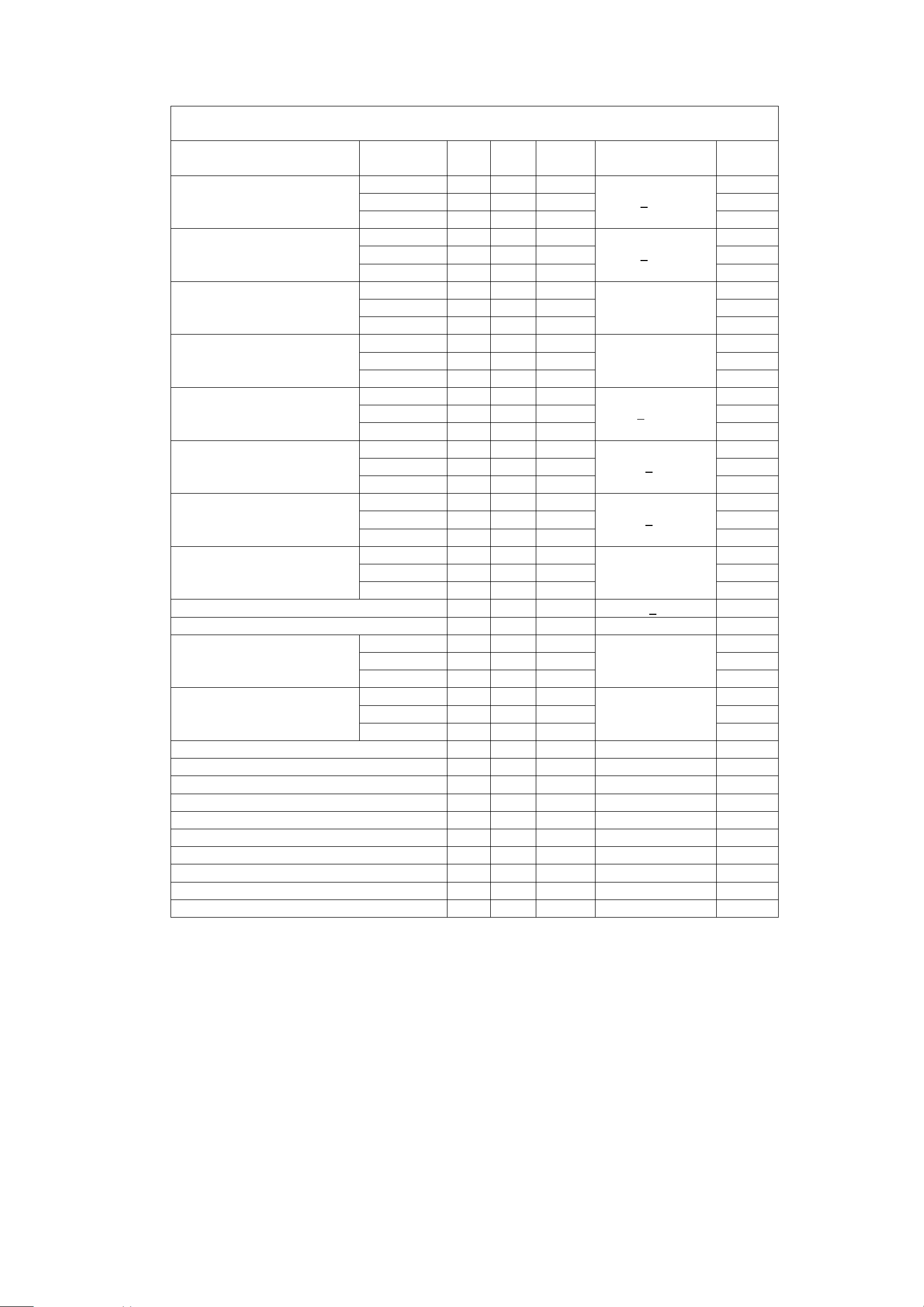
Radio Characteristics – Basic Data Rate
Radio Characteristics, VDD = 3.3V Temperature =+20°C
Freauency
(GHz)
Sensitivity at 0.1% BER
2.402 - -85 -83 dBm
2.441 - -85 -83 dBm
2.480 - -85 -83
Maximum received signal at
0.1% BER
2.402 0 - - dBm
2.441 0 - - dBm
2.480 0 - -
RF transmit power
(1)
2.402 -2 2 - dBm
2.441 -2 2 - dBm
2.480 -2 2 -
Initial carrier frequency tolerance
2.402 - 12 75 kHz
2.441 - 10 75 kHz
2.480 - 9 75
20dBm bandwidth for modulated
carrier
2.402 - 879 1000 kHz
2.441 - 816 1000 kHz
2.480 - 819 1000
Drift (single slot packet)
2.402 - - 25 kHz
2.441 - - 25 kHz
2.480 - - 25
Drift (five slot packet)
2.402 - - 40 kHz
2.441 - - 40 kHz
2.480 - - 40
Drift Rate
2.402 - - 20 kHz/50µs
2.441 - - 20 kHz/50µs
2.480 - - 20
Min Typ Max Bluetooth
Specification
- 70
<
- 20
>
(2)
-6 to +4
±75
1000
<
25
<
40
<
20
Unit
dBm
dBm
dBm
kHz
kHz
kHz
kHz
kHz/50µs
RF power control range 16 35 - >16 dB
RF power range control resolution - 1.8 - - dB
avg
△f1
“Maximum Moudulation”
maz
△f2
“Minimum Modulation”
C/I co-channel - 10 11
Adjacent channel selectivity C/I F=F0 +1 MHz
Adjacent channel selectivity C/I F=F0 - 1MHz
Adjacent channel selectivity C/I F=F0 +2 MHz
Adjacent channel selectivity C/I F=F0 - 2MHz
Adjacent channel selectivity C/I F>=F0 +3 MHz
Adjacent channel selectivity C/I F<=F0 -5 MHz
Adjacent channel selectivity C/I F=F
Adjacent channel transmit power F=F0±2MHz
Adjacent channel transmit power F=F0±3MHz
2.402 140 165 175 kHz
2.441 140 165 175 kHz
140<△f1
2.480 140 165 175
2.402 115 150 - kHz
2.441 115 150 - kHz
2.480 115 150 -
(3)(5)
- -4 0
(3)(5)
- -4 0
(3)(5)
- -35 -30
(3)(5)
- -21 -20
image
(3)(5)
(3)(5)
(3)(5)
(4)(5)
(4)(5)
- -45 -
- -45 -
- -18 -9
- -35 -20
- -55 -40
avg
115
<= 11
<= 0
<= 0
<= - 30
<= - 20
<= - 40
<= - 40
<= - 9
<= - 20
<= - 40
<175
kHz
kHz
dB
dB
dB
dB
dB
dB
dB
dB
dBc
dBc
Notes:
(1)
BlueCore-External firmware maintains the transmit power to be within the Bluetooth specification v2.0
limits.
(2)
Class 2 RF transmit power range, Bluetooth specification v2.0
(3)
Up to five exceptions are allowed in v2.0 of the Bluetooth specification
Page 3

(4)
Up to three exceptions are allowed in v2.0 of the Bluetooth specification
(5)
Measured at F0 = 2441MHz
Radio Characteristics – Enhanced Data Rate
Transmitter , VDD = 3.3V Temperature =+20°C
Frequency
(GHz)
Maximum RF transmit power
2.402 -6 0 +2 dBm
2.441 -6 0 +2 dBm
2.480 -6 0 +2
Min. Typ. Max. Bluetooth
Specification
-6 to +20
Unit
dBm
Relative transmit power - -1.2 - -4 to +1 dB
π/4 DQPSK
Maximum carrier frequency stability w
π/4 DQPSK
Maximum carrier frequency stability w
π/4 DQPSK
Maximum carrier frequency stability | w
8 DPSK
Maximum carrier frequency stability w
8 DPSK
Maximum carrier frequency stability w
8 DPSK
Maximum carrier frequency stability | w
π/4 DQPSK
Modulation Accuracy
RMS DVEM -
99% DEVM -
Peak DEVM 8 DPSK
Modulation Accuracy
RMS DVEM -
99% DEVM -
Peak DEVM In-band spurious emissions
F>F0 +3 MHz
0
i
+ wi |
0
0
i
+ wi |
0
- 2 -
- 6 -
- 8 -
- 2 -
- 6 -
- 8 -
7
13
19
7
13
17
- <-50 F<F0 -3 MHz - <-50 F=F0 -3 MHz - -46 F=F0 -2 MHz - -34 F=F0 -1 MHz - -35 F=F0 +1 MHz - -35 F=F0 +2 MHz - -31 -
+3 MHz - -33 -
F=F
0
EDR Differential Phase Encoding No
- < 20 %
- < 30 %
- <
- < 13 %
- < 20 %
- <
> 99 %
±10 for all blocks
<
±75 for all
<
packets
±75 for all blocks
<
±10 for all blocks
<
±75 for all
<
packets
< ±75 for all blocks
35 %
25 %
< -40
-40
<
-40
<
-20
<
-26
<
-26
<
-20
<
-40
<
kHz
kHz
kHz
kHz
kHz
kHz
dBm
dBm
dBm
dBm
dBm
dBm
dBm
dBm
Errors
Receiver , VDD = 3.3V Temperature =+20°C
Modulation Min. Typ. Max. Bluetooth
Specification
Sensitivity at 0.1% BER
Maximum received signal level
at 0.1% BER
C/I co-channel at 0.1% BER
Adjacent channel selectivity C/I
+1 MHz
F=F
0
Adjacent channel selectivity C/I
-1 MHz
F=F
0
π/4 DQPSK
- -87 8 DPSK - -78 π/4 DQPSK
- -8 8 DPSK - -10 π/4 DQPSK
- 10 8 DPSK - 19 π/4 DQPSK
- -10 8 DPSK - -5 π/4 DQPSK
- -11 8 DPSK - -5 -
< -70
-70
<
> -20
-20
>
< +13
+21
<
< 0
+5
<
< 0
+5
<
Unit
dBm
dBm
dBm
dBm
dB
dB
dB
dB
dB
dB
Page 4

Adjacent channel selectivity C/I
+2 MHz
F=F
0
Adjacent channel selectivity C/I
-2 MHz
F=F
0
Adjacent channel selectivity C/I
+3 MHz
F=F
0
Adjacent channel selectivity C/I
-5 MHz
F=F
0
F0 = 2405, 2441, 2477 MHz
Adjacent channel selectivity C/I
F=F
image
BTM-110 Pin Functions
PIN NAME TYPE FUNCTION REMARK
1 PIO(8) Bi-directional Programmable Input/Output line
2 PIO(9) Bi-directional Programmable Input/Output line
3 PIO(10) Bi-directional Programmable Input/Output line
4 AIO0 Bi-directional Programmable Input/Output Line
5 AIO1 Bi-directional Programmable Input/Output Line
6 RESET CMOS input Reset if high. Input debounced so must be high for >5ms
7 SPI_MISO CMOS Output Serial Peripheral Interface Data Output
8 SPI_CSB CMOS Input Chip Select For Synchronous Serial Interface active low
9 SPI_CLK CMOS Input Serial Peripheral Interface Clock
10 SPI_MOSI CMOS Input Serial Peripheral Interface Data Input
11 UART_CTS CMOS Input UART Clear To Send (Active Low)
12 UART_TX CMOS Output UART Data Output
13 UART_RTS CMOS Output UART Request To Send (Active Low)
14 UART_RX CMOS Input UART Data Input
15 PIO(11) Bi-directional Programmable Input/Output line
16 3V3 Power 3.3V Power Supply Input
17 GND GND Ground
18 PCM_OUT CMOS Output Synchronous Data Output
19 PCM_SYNC Bi-directional Synchronous Data Sync
20 PCM_IN CMOS Input Synchronous Data Input
21 PCM_CLK Bi-directional Synchronous Data Clock
22 USB_DP Bi-directional USB Data Plus
23 USB_DN Bi-directional USB Data Minus
24 PIO(7) Bi-directional Programmable Input/Output line
25 PIO(6) Bi-directional Programmable Input/Output line
26 PIO(5) Bi-directional Programmable Input/Output line
27 PIO(4) Bi-directional Programmable Input / Output Line
28 PIO(3) Bi-directional Programmable Input/Output Line
29 PIO(2) Bi-directional Programmable Input / Output Line
30 PIO(1) Bi-directional Programmable Input/Output Line
31 PIO(0) Bi-directional Programmable Input / Output Line
32 GND GND Ground
33 RF_IO Analogue Antenna Interface
34 GND GND Ground
π/4 DQPSK
- -40 8 DPSK - -40 π/4 DQPSK
- -23 8 DPSK - -20 π/4 DQPSK
- -45 8 DPSK - -45 π/4 DQPSK
- -45 8 DPSK - -45 -
π/4 DQPSK
-20
8 DPSK -15
to cause a reset
< -30
<
-25
< -20
-13
<
< -40
-33
<
< -40
-33
<
< -7
0
<
dB
dB
dB
dB
dB
dB
dB
dB
dB
dB
Page 5

BTM-110 Pin out Information
PIN DETAILS VIEWED FROM TOP SIDE
1 34
PIO(8) GND
PIO(9) RF_IO
PIO(10) GND
AIO( 0 ) PIO( 0)
AIO( 1 ) PIO( 1 )
RESET PIO( 2 )
SPI_ MISO PIO( 3 )
SPI_CSB PIO( 4 )
SPI_CLK PIO( 5 )
SPI_MOSI PIO( 6 )
UART_CTS PIO( 7 )
UART_TX USB_DN
UART_RTS USB_DP
UART_RX PCM_CLK
PIO(11) PCM_IN
3V3 PCM_SYNC
GND PCM_OUT
17 18
MODULE PAD AND SOLDER MASK DETALS
SOLDER MASK WINDOW 1.0mm MAX
SOLDER PAD 0.8mm
MECHANICAL DETAILS VIEWED FROM TOP/BOTTOM SIDE
Design to M icro Strip Line
PCB Layout (Top V iew)
 Loading...