

Page 1
BR24L04-W / BR24L04F-W / BR24L04FJ-W
Memory ICs BR24L04FV-W / BR24L04FVM-W
512×8 bit electrically erasable PROM
BR24L04-W / BR24L04F-W / BR24L04FJ-W /
BR24L04FV -W / BR24L04FVM-W
The BR24L04-W series is 2-wire (I2C BUS type) serial EEPROMs which are electrically programmable.
∗ I2C BUS is a registered trademark of Philips.
zApplications
General purpose
zFeatu res
1) 512 registers × 8 bits serial architecture.
2) Single power supply (1.8 V to 5.5V).
3) Two wire serial interface.
4) Self-timed write cycle with automatic erase.
5) 16byte Page Write mode.
6) Low power consumption.
Write
Read (5V) : 0.2mA (Typ.)
Standby (5V) : 0.1µA (Typ.)
7) DATA security
Write protect feature (WP pin).
Inhibit to WRITE at low V
8) Small package - - - DIP8 / SOP8 / SOP-J8 / SSOP-B8 / MSOP-8
9) High reliability EEPROM with Double-Cell structure
10) High reliability fine patte rn CMOS te chnology.
11) Endurance : 1,000,000 erase / write cycles
12) Data retention : 40 years
13) Filtered inputs in SCL
14) Initial data FFh in all address.
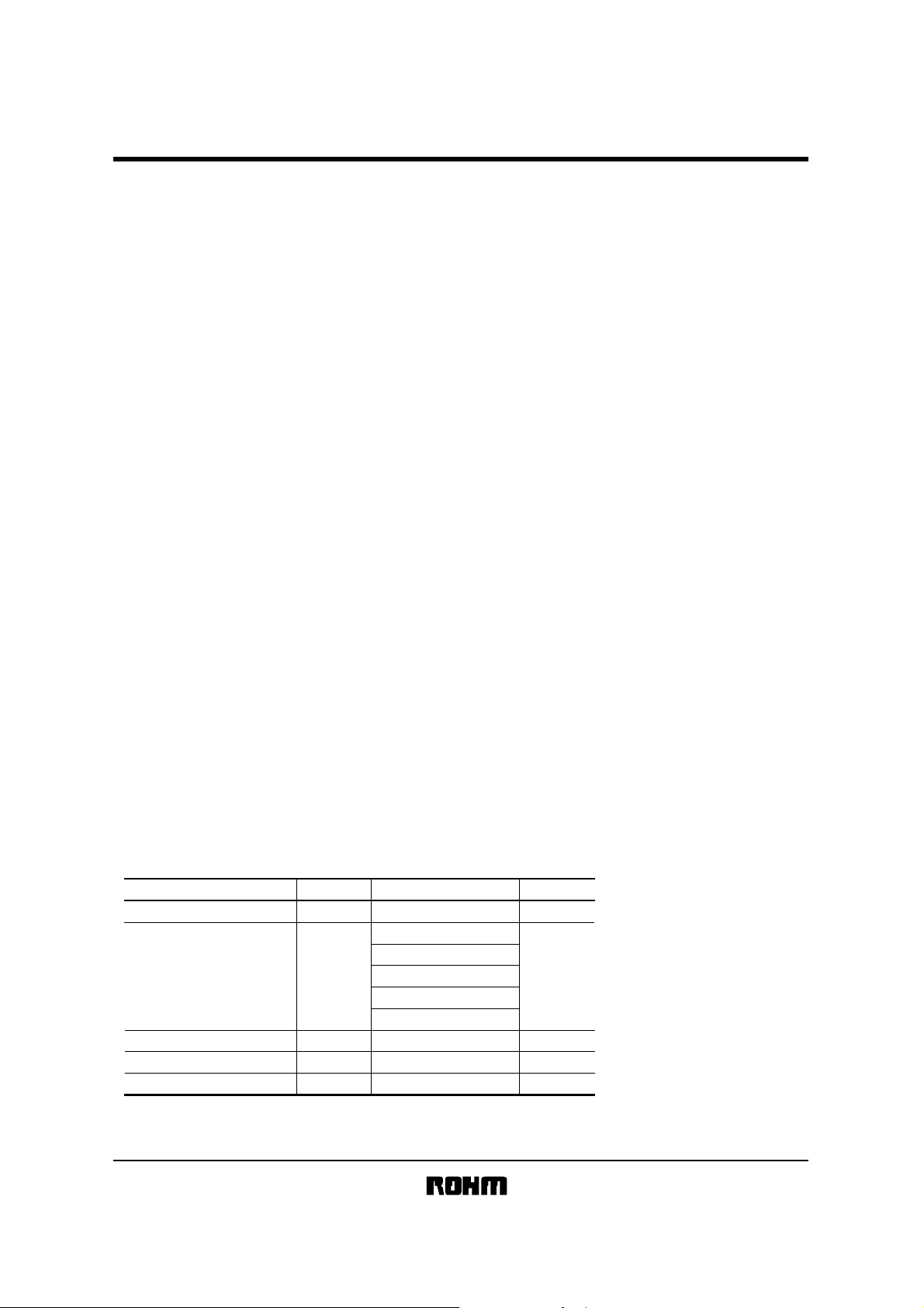
zAbsolute maximum ratings (T a=25°C)
Supply voltage −0.3 to +6.5 V
Power dissipation mW
Storage temperature
Operating temperature
Terminal voltage
∗1 Reduced by 8.0mW for each increase in Ta of 1°C over 25°C.
∗2 Reduced by 4.5mW for each increase in Ta of 1°C over 25°C.
∗3 Reduced by 3.0mW for each increase in Ta of 1°C over 25°C.
∗4 Reduced by 3.1mW for each increase in Ta of 1°C over 25°C.
(5V) : 1.2mA (T yp.)
CC.
•SDA for noise suppression.
Parameter Symbol Limits Unit
V
CC
∗1
∗2
∗2
∗3
∗4
°C
°C
V
Pd
Tstg
Topr
−
800(DIP8)
450(SOP8)
450(SOP-J8)
300(SSOP-B8)
310(MSOP8)
−65 to +125
−40 to +85
−0.3 to VCC+0.3
1/25
Page 2
BR24L04-W / BR24L04F-W / BR24L04FJ-W
Memory ICs BR24L04FV-W / BR24L04FVM-W
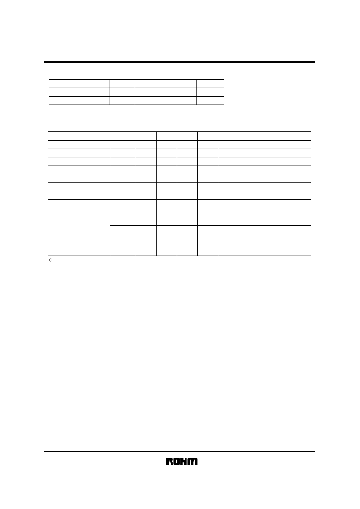
zRecommended operating conditions (Ta=25°C)
Parameter Symbol Limits Unit
CC
Supply voltage
Input voltage V
zDC operating charac teristics (Unless otherwise specified Ta=−40 to 85°C, VCC=1.8 to 5.5V)
Parameter Symbol Min. Typ. Max. Unit Conditions
"HIGH" input volatge 1
"LOW" input volatge 1
"HIGH" input volatge 2
"LOW" input volatge 2
"LOW" output volatge 1
"LOW" output volatge 2
Input leakage current I
Output leakage current I
Operating current
Standby current I
This product is not designed for protection against radioactive rays.
V
IN
IH1
IL1
IH2
IL2
OL1
OL2
LI
LO
SB
0.7V
0.8V
V
V
V
V
V
V
I
CC1
CC2
I
1.8 to 5.5
0 to V
CC
CC
−−
−−
CC
−−
−−
−−
−−
−1
−
−1 −
−
−
−
−
−
−
CC
0.3V
CC
0.2V
0.4 V
0.2 V
1 µA
1 µA
2.0 mA
0.5 mA
2.0
V
V
V
V
V
V
CC
2.5V≤V
≤5.5V
2.5V≤VCC≤5.5V
CC
1.8V≤V
<2.5V
1.8V≤VCC<2.5V
IOL=3.0mA, 2.5V≤VCC≤5.5V, (SDA)
OL
=0.7mA, 1.8V≤VCC≤5.5V, (SDA)
I
VIN=0V to V
OUT
V
V
CC
=0V to V
=5.5V, f
CC
CC
SCL
=400kHz, tWR=5ms,
Byte Write, Page Write
CC
=5.5V, f
SCL
V
Random Read, Current Read,
Sequential Read
CC
=5.5V, SDA•SCL=VCC,
V
µA
A0, A1, A2=GND, WP=GND
=400kHz
2/25
Page 3
BR24L04-W / BR24L04F-W / BR24L04FJ-W
Memory ICs BR24L04FV-W / BR24L04FVM-W
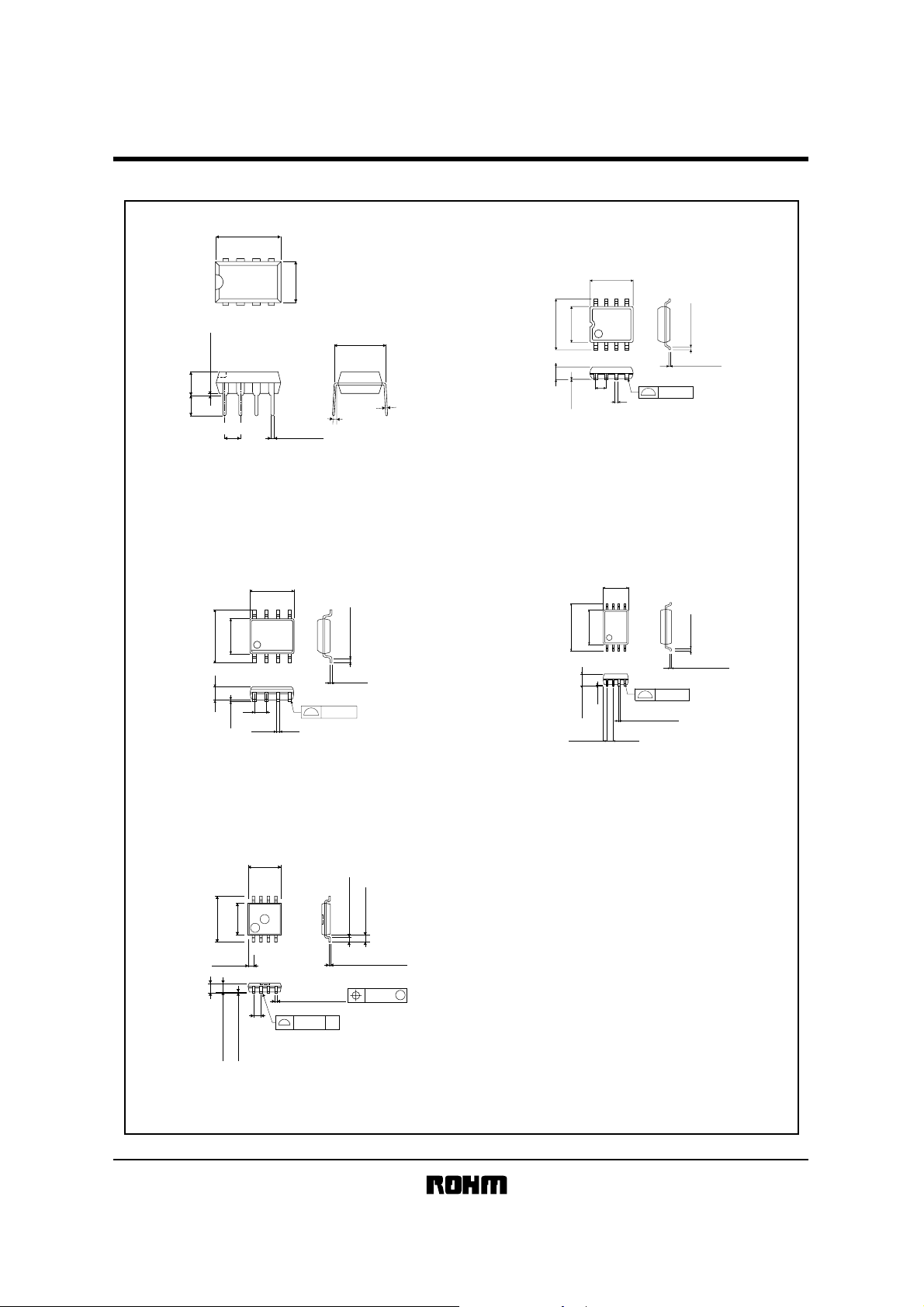
zDimension
9.3±0.3
85
5.0±0.2
6.2±0.3
1.5±0.1
85
4.4±0.2
1.27
0.11
41
0.4±0.1
0.3Min.
0.15±0.1
0.1
14
0.51Min.
0.3
±
3.4
0.2
±
2.54
3.2
0.5±0.1
6.5±0.3
7.62
0.3±0.1
0° ~ 15°
Fig.1(a) PHYSICAL DIMENSION (Units : mm)
DIP8 (BR24L04-W)
4.9±0.2
85
76
6.0±0.3
3.9±0.2
1.375±0.1
0.175
Fig.1(c) PHYSICAL DIMENSION (Units : mm)
DOP-J8 (BR24L04FJ-W)
4123
1.27
0.42±0.1
0.45Min.
0.2±0.1
0.1
2.9±0.1
58
0.1
4.0±0.2
0.475
±
2.8
41
0.29±0.15
0.145
0.6±0.2
+0.05
−0.03
Fig.1(b) PHYSICAL DIMENSION (Units : mm)
SOP8 (BR24L04F-W)
3.0±0.2
548
0.2
±
4.4
6.4±0.3
1
0.1
0.22±0.1
1.15±0.1
(0.52)
Fig.1(d) PHYSICAL DIMENSION (Units : mm)
SSOP-B8 (BR24L04FV-W)
0.65
0.3Min.
0.15±0.1
0.1
+0.05
0.22
0.9Max.
0.65
0.75±0.05
0.08±0.05
Fig.1(e) PHYSICAL DIMENSION (Units : mm)
MSOP8 (BR24L04FVM-W)
−0.04
0.08 S
0.08
M
3/25
Page 4
BR24L04-W / BR24L04F-W / BR24L04FJ-W
Memory ICs BR24L04FV-W / BR24L04FVM-W
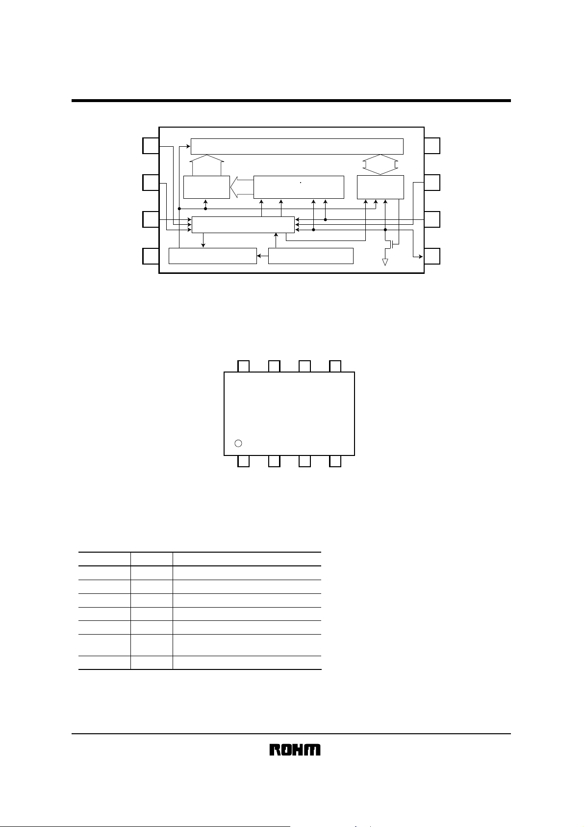
zBlock diagram
A1 2
A2 3
GND 4
zPin configuration
1A0
9bit
Address
decoder
Control logic
High voltage generator Vcc level detect
4kbit EEPROM array
9bits
V
address register
Fig.2 BLOCK DIAGRAM
CC
WP
BR24L04-W
BR24L04F-W
BR24L04FJ-W
BR24L04FV-W
BR24L04FVM-W
Slave word
STOPSTART
SCL
SDA
5678
ACK
8bit
Data
register
V
CC8
WP7
6 SCL
SDA5
zPin name
Pin name
CC
V
GND
A1, A2
SCL
SDA
WP
∗1 An open drain output requires a pull-up resistor.
I / O
−
−
−
IN
IN
IN / OUT
IN
Power supply
Ground (0V)
Out of useA0
Slave address set
Serial clock input
Slave and word address,
serial data input, serial data output
Write protect input
1234
A0
Function
A1
Fig.3 PIN LAYOUT
A2
∗1
GND
4/25
Page 5
BR24L04-W / BR24L04F-W / BR24L04FJ-W
Memory ICs BR24L04FV-W / BR24L04FVM-W
zAC operating characteristics (Unless otherwise specified Ta=−40 to 85°C, V
Fast-mode
Parameter Symbol
Clock frequency
Data clock "HIGH" period
Data clock "LOW" period tLOW
SDA and SCL rise time
SDA and SCL fall time tF
Start condition hold time
Start condition setup time
Input data hold time
Input data setup time
Output data delay time
Output data hold time
Stop condition setup time
Bus free time
Write cycle time
Noise spike width (SDA and SCL)
WP hold time
WP setup time
WP high period
∗1 Not 100% tested.
∗1
∗1
fSCL kHz
tHIGH
tR
tHD:STA
tSU:STA
tHD:DAT ns
tSU:DAT ns
tPD
tDH
tSU:STO µs
tBUF
tWR
tl
tHD:WP
tSU:WP
tHIGH:WP
2.5V ≤ Vcc ≤ 5.5V
Min.
Typ.
−
−
0.6
−
1.2
−
−
−
−
−
0.6
−
0.6
−
0
−
100
0.1
0.1
0.6
1.2
−
−
0
0.1
1.0
−
−
−
−
−
−
−
−
−−
−−
CC=1.8 to 5.5V)
1.8V ≤ Vcc ≤ 5.5V
Max.
Min.
400
4.0
−
4.7
−
0.3
0.3
4.0
−
4.7
−
−
250
−
0.9
0.2
0.2
−
−
4.7
−
4.7
5
0.1
−
0.1
1.0
Standard-mode
Typ.
−
−
−
−
−
−
−
−
−
−
0
−
−
−
−
−
−
−
−
−
−
0
−
−−
−−
Max.
100
−
−
1.0
0.3
−
−
−
−
3.5
−
−
−µs
5
0.1
−
Unit
µs
µs
µs
µs
µs
µs
µs
µs
ms
µs
ns
µs
µs
5/25
Page 6
BR24L04-W / BR24L04F-W / BR24L04FJ-W
Memory ICs BR24L04FV-W / BR24L04FVM-W
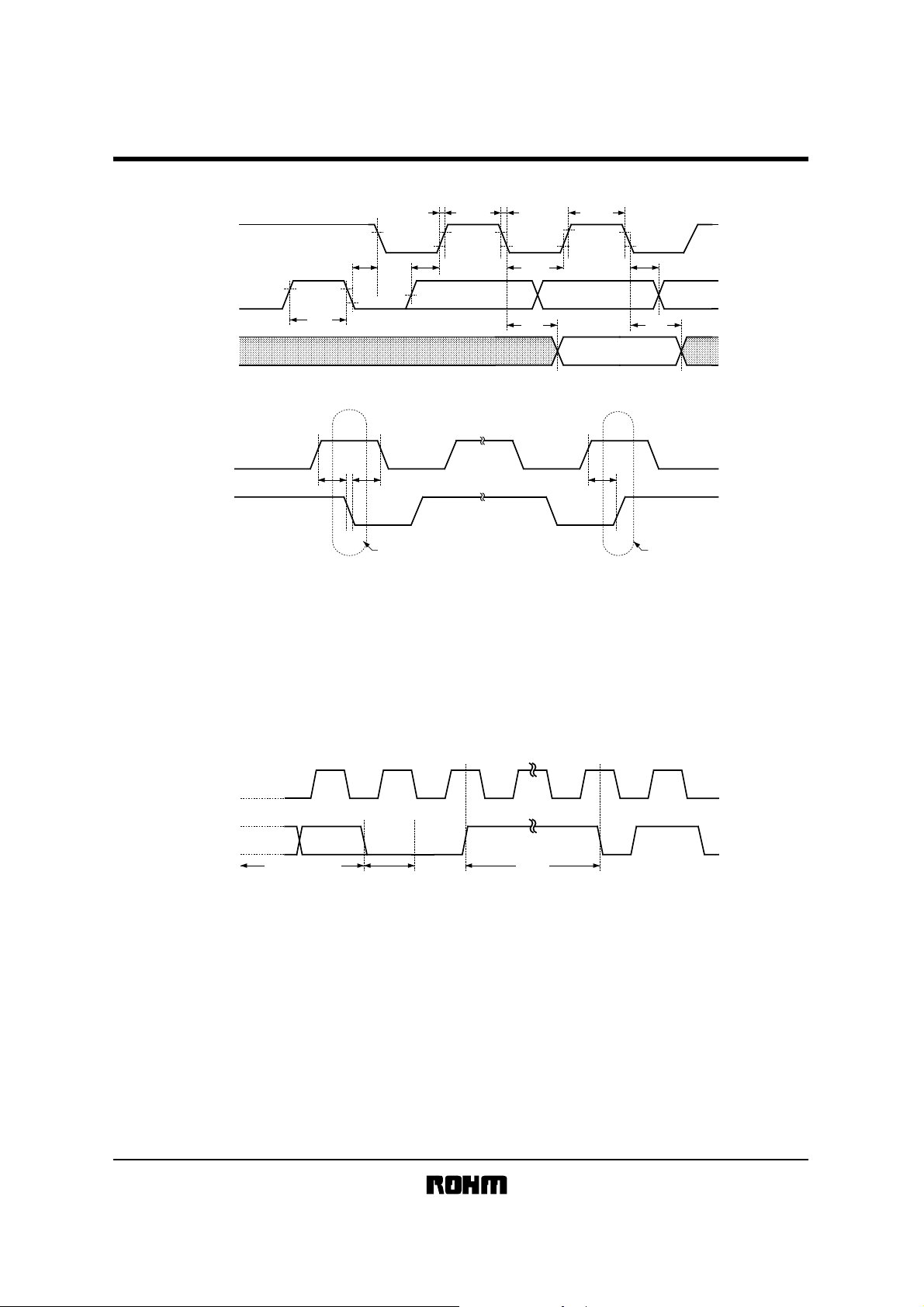
zSynchronous dat a timing
t
HIGH
t
DH
SCL
SDA
(IN)
SDA
(OUT)
t
R
t
HD :
STA t
t
BUF
tSU : DAT tHD : DAT
t
F
LOW
t
PD
SCL
SDA
START BIT STOP BIT
Fig.4 SYNCHRONOUS DATA TIMING
•SDA data is latched into the chip at the rising edge of SCL clock.
•Output data toggles at the falling edge of SCL clock.
zWrite cy cle timing
SCL
SDA
WRITE DATA (n)
ACKD0
tSU : STOtHD : STAtSU : STA
t
WR
START CONDITIONSTOP CONDITION
Fig.5 WRITE CYCLE TIMING
6/25
Page 7
BR24L04-W / BR24L04F-W / BR24L04FJ-W
Memory ICs BR24L04FV-W / BR24L04FVM-W
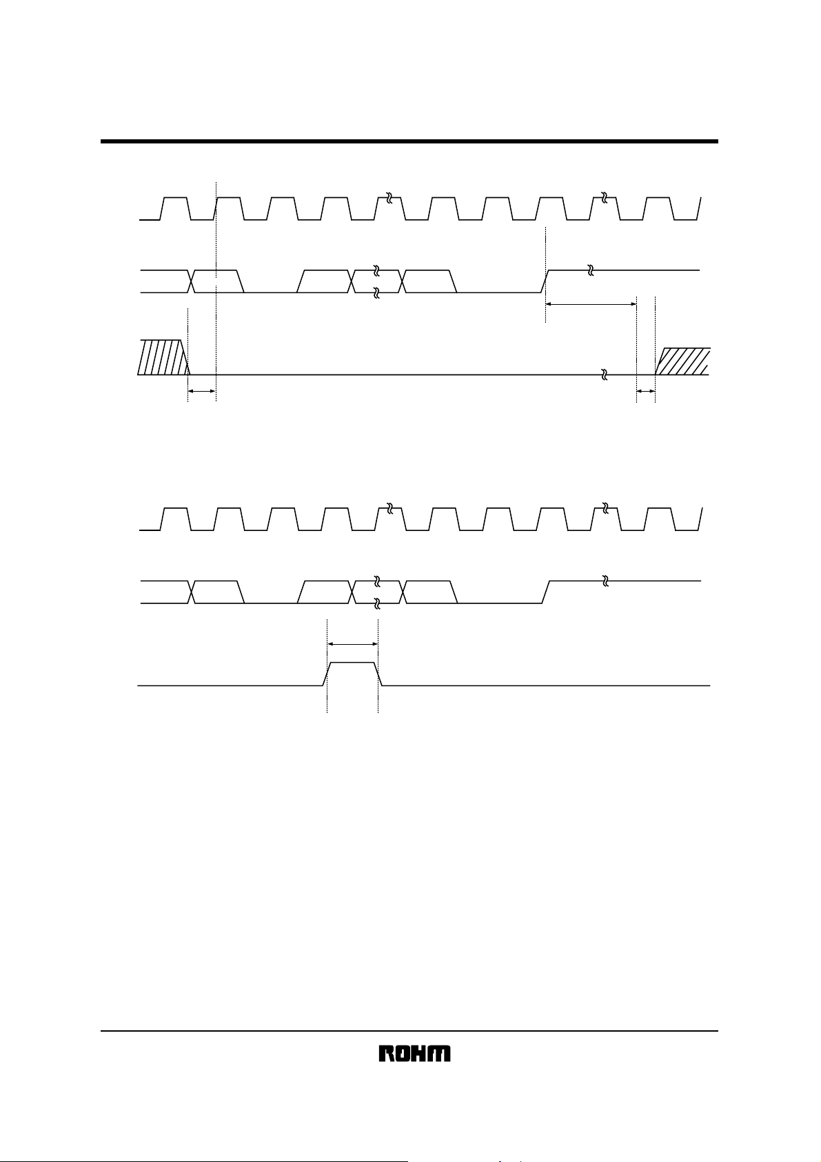
zWP timing
SCL
DATA (n)DATA (1)
SDA
WP
SCL
SDA
WP
D1
D1
t
SU : WP
D0
Fig.6(a) WP TIMING OF THE WRITE OPERATION
DATA (n)DATA (1)
D0
t
HIGH : WP
ACKACK
t
WR
STOP BIT
t
HD : WP
ACKACK
Fig.6(b) WP TIMING OF THE WRITE CANCEL OPERATION
•For the WRITE operation, WP must be “LOW” during the period of time from the rising edge of the clock which takes in
D0 of first byte until the end of t
WR. ( See Fig.6 (a) )
During this period, WRITE operation is canceled by setting WP “HIGH”. ( See Fig.6 (b) )
•In the case of setting WP “HIGH” during tWR, WRITE operation is stopped in the middle and the data of accessing
address is not guaranteed. Please write correct data again in the case.
7/25
Page 8

BR24L04-W / BR24L04F-W / BR24L04FJ-W
Memory ICs BR24L04FV-W / BR24L04FVM-W
zDevice operation
1) Start condi tion (Recognition of st art bit)
• All commands are proceeded by the start condition, which is a HIGH to LOW transition of SDA when SCL is HIGH.
• The device continuously monitors the SDA and SCL lines for the start condition and will not respond to any command
until this condition has been met. (See Fig.4 SYNCHRONOUS DAT A TIMING)
2) Stop conditio n (Recognition of sto p bit)
• All communications must be terminated by a stop condi tion, which is a LOW to HIGH transition of SDA when SCL is
HIGH. (See Fig.4 SYNCHRONOUS DAT A TIMING)
3) Notice about write command
• In the case that stop condition is not executed in WRITE mode, transferred dat a will not be w ritten in a memory.
4) Device addressing
• Following a START condition, the master output the slave address to be accessed.
• The most significant four bits of the slave address are the “device type identifier”, for this device it is fixed as “1010”.
• The next two bit (device address) identify the specified device on the bus.
The device address is defined by the state of A1 and A2 input pins. This IC works only when the device address
inputted from SDA pin correspond to the state of A1 and A2 input pins. Using this address scheme, up to four
devices may be connected to the bus. The next bit (PS) is used by the master to select two 256 word page of
memory.
PS set to “0” - - - - - - 1page (000 to 0FF)
PS set to “1” - - - - - - 2page (100 to 1FF)
• The last bit of the stream (R/W - - - READ / WRITE) determines the operation to be performed. When set to “1”, a read
operation is selected ; when set to “0”, a write operation is selected.
R / W set to “0” - - - - - - WRITE (including word address input of Random Re ad)
R / W set to “1” - - - - - - READ
5) Write protect (WP)
When WP pin set to V
When WP pin set to GND (L level), e nable to write 512 words (all address).
Either control this pin or connect to GND (or V
A2 A1 PS1010 R / W
CC (H level), write protect is set for 512 words (all address).
CC). It is inhibited from being left unconnected.
8/25
Page 9

BR24L04-W / BR24L04F-W / BR24L04FJ-W
Memory ICs BR24L04FV-W / BR24L04FVM-W
6) Acknowledge
• Acknowledge is a software con vention used to indi cate successful dat a transfers.
The transmitter device w ill release the bus af ter transmitting eig ht bits.
(When inputting the slave address in the write or read operation, transmitter is µ-COM. When outputting the data in
the read operation, it is this device.)
• During the ninth clock cycle, the receiver will pull the SDA line L OW to acknowledge tha t the eight bit s of data has
been received.
(When inputting the slave address in the write or read operation, receiver is this device. When outputting the data in
the read operation, it is µ-COM.)
• The device will respond with an Acknowledge af ter recognition o f a ST AR T condition and its slave addre ss (8bit).
• In the WRITE mode, the device will respond with an Acknowledge, af ter the receipt of ea ch subsequent 8-bit w ord
(word address and write data).
• In the READ mode, the device will transmit eight bit of data, rele ase the SDA line, and monitor the line fo r an
Acknowledge.
• If an Acknowledge is detected, and no STOP cond ition is generated by the ma ster , the device w ill continue to transmit
the data. If an Acknow ledge is not detected, th e device will termina te further data transmissions an d await a STOP
condition before returning to the standby mode. (See Fig.7 ACKNOWLEDGE RESPONSE FROM RECEIVER)
START CONDITION
(START BIT)
SCL
(From µ−COM)
SDA
(µ−COM
OUTPUT DATA)
SDA
(IC OUTPUT DATA)
Fig.7 ACKNOWLEDGE RESPONSE FROM RECEIVER
189
Acknowledge Signal
(ACK Signal)
9/25
Page 10

BR24L04-W / BR24L04F-W / BR24L04FJ-W
Memory ICs BR24L04FV-W / BR24L04FVM-W
zByte write
S
T
A
R
T
SLAVE
ADDRESS
W
R
I
T
E
WORD
ADDRESS
DATA
S
T
O
P
SDA
LINE
10 01
PSA1A2
WA
7
R
A
/
C
W
K
WA
D7
0
A
C
K
D0
A
C
K
WP
Fig.8 BYTE WRITE CYCLE TIMING
• By using this command, the data is programmed into the indicated word address.
• When the master generates a STOP condition, the device begins the internal write cycle to the nonvolatile memory
array.
zPage write
S
T
A
R
T
SLAVE
ADDRESS
W
R
I
T
E
WORD
ADDRESS (n)
DATA (n)
DATA (n+15)
S
T
O
P
SDA
LINE
10 01
WA
PSA1A2
7
R
A
/
C
W
K
WA
D7
0
A
C
K
D0
D0
A
C
K
A
C
K
WP
Fig.9 PAGE WRITE CYCLE TIMING
• This device is capable of sixteen byte Page Write operation.
• When two or more byte data are inputted, the four low order address bits are internally incremented by one after the
receipt of each word. The five higher order bits of the address (PS WA7 to WA4) remain constant.
• If the master transmits more than sixteen words, prior to generati ng the STOP condition, the address cou nter will
“roll over”, and the pre vious tran smitted dat a will be overwritte n.
10/25
Page 11

BR24L04-W / BR24L04F-W / BR24L04FJ-W
Memory ICs BR24L04FV-W / BR24L04FVM-W
zCurrent read
S
T
A
R
T
SLAVE
ADDRESS
R
E
A
D
DATA
S
T
O
P
SDA
LINE
11
00
A2 A1 PS
Fig.10 CURRENT READ CYCLE TIMING
D7 D0
R
A
/
C
W
K
A
C
K
• In case that the previous operation is Random or Current Read (which includes Sequential Read respectively), the
internal address counter is increased by one from the last accessed address (n).
Thus Current Read outputs the data of the next word address (n+1).
If the last command is Byte or Page Write, the internal address counter stays at the last address (n).
Thus Current Read outputs th e data of the w ord address (n).
• If an Acknowledge is detected, and no STOP cond ition is generated by the ma ster (µ-COM), the device will continue
to transmit the data. [ It can transmit all data (4kbit 512word) ]
• If an Acknowledge is not detected, the de vice will terminat e further data tra nsmissions and aw ait a STOP cond ition
before returning to the standby mode.
Note) If an Acknowledge is detected with “Low” level, no t “High” level, comma nd will become Seq uential Read.
So the device transmits the next data, Read is not terminated. In the case of terminating Read, input
Acknowledge with “High” always, then input stop condition.
zRandom read
S
T
A
R
T
SLAVE
ADDRESS
W
R
I
T
E
WORD
ADDRESS(n)
S
T
A
R
T
SLAVE
ADDRESS
R
E
A
D
DATA(n)
S
T
O
P
SDA
LINE
110 0 A2A1PS A2A1PS
WA
7
R
A
C
/
K
W
Fig.11 RANDOM READ CYCLE TIMING
WA
110 0 D7 D0
0
A
C
K
R
A
/
C
W
K
A
C
K
• Random read operation allows the master to access any memory location indicated word address.
• If an Acknowledge is detected, and no STOP cond ition is generated by the ma ster (µ-COM), the device will continue to
transmit the data. [ It can transmit all data (4kbit 512word) ]
• If an Acknowledge is not detected, the de vice will terminat e further data tra nsmissions and aw ait a STOP cond ition
before returning to the standby mode.
Note) If an Acknowledge is detected with “Low” level, not “High” level, co mmand will become Se quential Read.
So the device transmits the next data, Read is not terminated. In the case of terminating Read, input
Acknowledge with “High” always, then input stop condition.
11/25
Page 12

BR24L04-W / BR24L04F-W / BR24L04FJ-W
Memory ICs BR24L04FV-W / BR24L04FVM-W
zSequential read
S
T
A
R
T
SLAVE
ADDRESS
R
E
A
D
DATA(n)
DATA(n+x)
S
T
O
P
SDA
LINE
1100A2
A1PS
D7 D7D0 D0
A
R
C
/
K
W
Fig.12 SEQUENTIAL READ CYCLE TIMING
(Current Read)
A
C
K
A
C
K
A
C
K
• If an Acknowledge is de tected, and no ST OP condition is generated by the master (µ-COM), the device will continue to
transmit the data. [ It can transmit all data (4kbit 512word) ]
• If an Acknowledge is no t detected, the device w ill terminate fu rther data transmissio ns and await a ST OP conditio n
before returning to the standby mode.
• The Sequential Read operation can be performed with both Current Read and Random Read.
Note) If an Acknowledge is detected with “Low” le vel, not “High” level , command will beco me Sequential Read .
So the device transmits the next data, Read is not terminated. In the case of terminating Read, input
Acknowledge with “High” always, then input stop condition.
12/25
Page 13

BR24L04-W / BR24L04F-W / BR24L04FJ-W
Memory ICs BR24L04FV-W / BR24L04FVM-W
zApplication
1) WP effec tive timing
WP is fixed to “H” or “L” usually. But in case of controlling WP to cancel the write command, please pay attention to
[ WP effective timing ] as follows.
During write command input, write command is canceled by controlling WP “H” within the WP cancellation effective
period.
The period from the start condition to the rising edge o f the clock which ta ke in D0 of the data (the first by te of the data
for Page Write) is the cancellation invalid period. WP input is don’t care during the period. Setup time for rising edge of
the SCL which takes in D0 must be more than 100ns.
The period from the rising edge of SCL which takes in D0 to the end of internal write cycle (t
effective period. In case of setting WP to “H” during t
WR, WRITE operation is stopped in th e middle and the data of
accessing address is not guaranteed, so that write correct data again please.
It is not necessary waiting t
WR (5msmax.) after stopping command by WP , because the device is stand by state.
· The rising edge of the clock
which take in D0
WR) is the cancellation
SDA
WP
S
T
A
R
T
SCL
SDA D1 D0 ACK
AN ENLARGEMENT
A
SLAVE
ADDRESS
WORD
C
ADDRESS
K
L
WP cancellation invalid period WP cancellation effective period
A
C
K
L
A
C
K
L
No data will be written
Fig.13 WP EFFECTIVE TIMING
SCL
SDA D0 ACK
A
C
DATAD7 D6 D5 D4 D3 D2 D1 D0
K
L
AN ENLARGEMENT
A
S
C
T
K
O
L
P
· The rising edge
of SDA
tWR
Stop of the write
operation
Data is not
guaranteed
13/25
Page 14

BR24L04-W / BR24L04F-W / BR24L04FJ-W
Memory ICs BR24L04FV-W / BR24L04FVM-W
2) Software re set
Please execute software reset in case that the device is an unexpected state after power up and / or the command
input need to be reset.
There are some kinds of software reset. Here we show three types of example as follows.
During dummy clock, please release SDA bus (tied to V
During that time, the device may pull the SDA line L OW for Acknowledge or ou tputting or read dat a.
If the master controls the SDA line HIGH , it will conflict with the device output LOW then it makes a current overloa d.
It may cause instantaneous power down and may damage th e device.
DUMMY CLOCK × 14 START × 2
CC by pull up resistor).
SCL
SDA
12 1413
Fig.14-(a) DUMMY CLOCK × 14 + START + START
COMMAND
COMMAND
START START
SDA
Fig.14-(b) START+ DUMMY CLOCK × 9 + START
DUMMY CLOCK × 9
12 89SCL
COMMAND
COMMAND
START × 9
123 789SCL
COMMAND
SDA
∗ COMMAND st arts w ith sta rt condition.
Fig.14-(c) START × 9
COMMAND
14/25
Page 15

BR24L04-W / BR24L04F-W / BR24L04FJ-W
Memory ICs BR24L04FV-W / BR24L04FVM-W
3) Acknowledge polling
Since the device ignore all input commands during the internal write cycle, no ACK will be returned.
When the master send the next command after the write command, if the device returns the ACK, it means that the
program is completed. If no ACK id returned, it means that the device is still busy.
By using Acknowledge polling, the waiting time is min imized less than t
In case of operating Write or Current Read right after Write, first, send the slave address (R / W is “HIGH” or “LOW”
respectively). After the device returns the ACK, continue word address input or data output respectively.
THE FIRST WRITE COMMAND
WR=5ms.
During the internal write cycle,
no ACK will be returned.
(ACK=HIGH)
• • •
S
T
A
R
T
WRITE COMMAND
S
T
SLAVE
A
ADDRESS
R
T
tWR
S
T
O
P
A
C
K
H
Fig.15 SUCCESSIVE WRITE OPERATION BY ACKNOWLEDGE POLLING
S
T
SLAVE
A
ADDRESS
R
T
S
T
SLAVE
A
ADDRESS
R
T
A
C
K
H
THE SECOND WRITE COMMAND
A
C
WORD
K
ADDRESS
L
S
T
SLAVE
A
ADDRESS
R
T
tWR
A
C
K
L
After the internal write cycle
is completed ACK will be returned
(ACK=LOW). Then input next
Word Address and data.
DATA
C
K
H
A
• • •
A
S
C
T
K
O
L
P
15/25
Page 16

BR24L04-W / BR24L04F-W / BR24L04FJ-W
Memory ICs BR24L04FV-W / BR24L04FVM-W
4) Command cancellation by start and stop condition
During a command input, it is canceled by the successive inputs of start condition and stop condition. (Fig.4)
But during ACK or data output, the device may output the SDA line LOW. In such cases, operation of start and stop
condition is impossible, so that the reset can’t work. Execute the software reset in the cases. (See Page14)
Operating the command cancel by start and stop condition during the command of Random Read or Sequential Read
or Current Read, internal address counter is not confirmed.
Therefore operation of Current Read after this in not valid. Operate a Random Read in this case.
SCL
SDA
Fig.16 COMMAND CANCELLATION BY START AND STOP CONDITION
DURING THE INPUT OF SLAVE ADDRESS
1100
START
CONDITION
STOP
CONDITION
16/25
Page 17

BR24L04-W / BR24L04F-W / BR24L04FJ-W
Memory ICs BR24L04FV-W / BR24L04FVM-W
5) Notes for power supply
V
CC rises through the low voltage region in which internal circuit of IC and the controller are unstable, so that device
may not work properly due to an incomplete reset of internal circuit.
To prevent this, the device has the feature of P .O.R. and LVCC.
In the case of power up, keep the following conditions to ensure functions of P.O.R and LV
(1) It is necessary to be “SDA=‘H’ ” and “SCL=’L’ or ‘H’ ”.
(2) Follow the recommended conditions of t
R, tOFF, Vbot for the function of P.O.R. durning power up.
t
R
CC
V
t
OFF
0
V
CC
rising wave from
Vbot
Recommended conditions of t
R
t
Below 10ms
Below 100ms
Above 10ms
Above 10ms
(3) Prevent SDA and SCL from being “Hi-Z”.
In case that condition 1. and / or 2. cannot be met, take following actions.
A) Unable to keep condition 1. (SDA is “LOW” during pow er up.)
→Control SDA, SCL to be “HIGH” as figure below .
CC.
R
, t
OFF
, Vbot
t
OFF
Vbot
Below 0.3V
Below 0.2V
V
CC
SCL
SDA
After VCC becomes stable
a) SCL="H" and SDA="L"
t
LOW
After VCC becomes stable
t
DH
t
SU:DAT
b) SCL="L" and SDA="L"
t
SU:DAT
B) Unable to keep condition 2.
→ After power becomes stable, execute software reset. (See Page14 )
C) Unable to keep condition 1 and 2.
→ Follow the instruction A first, then the instruction B.
• LV
CC circuit
LV
CC circuit inhibit write operation at low voltage, and prevent an inadvertent write. Below the LVCC voltage
(Typ.=1.2V), write operation is inhibited.
17/25
Page 18

BR24L04-W / BR24L04F-W / BR24L04FJ-W
Memory ICs BR24L04FV-W / BR24L04FVM-W
6) I / O circuit
• Pull up resister of SD A pin
The pull up resister is needed because SDA is NMOS open drain. Decide the value of this resister (R
by considering V
If large R
IL, IL characteristics of a controller which control the device and VOH, IOL characteristics of the device.
PU is chosen, clock frequency need to be slow . In case of small RPU, the operating current increases.
• Maximum of R
Maximum of R
c SDA rise time determined by R
And the other timing must keep the conditions of AC spec.
d When SDA bus is HIGH, the voltage A of SDA bus determined by a total input leak (I
connected to the bus and RPU must be enough higher than input HIGH level of a controller and the device,
including noise margin 0.2VCC.
PU
PU is determined by following fa ctor .
PU and the capacitance of bus line (CBUS) must be less than TR.
L) of the all devices
VCC − ILRPU − 0.2VCC ≥ V
IH
PU) properly,
0.8VCC − V
RPU ≤
IL
Examples : When V
According to
R
PU
≤
≤ 300 [kΩ]
IH
CC
=3V IL=10µA VIH=0.7V
2
0.8×3−0.7×3
−6
10×10
MICRO
COMPUTER
CC
PU
R
IL IL
THE CAPACITANCE OF
BUS LINE (CBUS)
BR24LXX
A
SDA PIN
18/25
Page 19

BR24L04-W / BR24L04F-W / BR24L04FJ-W
Memory ICs BR24L04FV-W / BR24L04FVM-W
• The minimum value R
The minimum value of R
c Meet the condition that V
VCC − V
R
PU
RPU ≥
d V
OLMAX (=0.4V) must be lower than the input LOW level of the controller and the EEPROM including
recommended noise margin (0.1 VCC).
V
Examples : V
PU
PU is determined by following factors.
OLMAX=0.4V, IOLMAX=3mA when the device output low on SDA line.
OL
≤ I
OL
VCC − V
OL
I
OL
OLMAX
≤ VIL − 0.1V
CC
=3V, VOL=0.4V, IOL=3mA, the VIL of the controller and the EEPROM is VIL=0.3V
CC
CC
RPU ≥
OL
V
V
IL
3−0.4
3×10
≥ 867 [Ω]
=0.4[V]
=0.3×3
=0.9[V]
−3
According to
and
so that condition is met
1
2
• Pull up resister of SCL pin
In the case that SCL is controlled by CMOS output, the pull up resister of SCL is not needed .
But in the case that there is a timing at which SCL is Hi-Z, connect SCL to VCC with pull up resister.
Several ∼ several dozen kΩ is recommended as a pull up resister, which is considered with the driving ability of the
output port of the controller.
7) Connections of A0, A1, A2, WP pin
• Connections of device address pin (A0, A1, A2)
The state of device address PIN are compared with the device address send by the master, then one of the devices
which are connected to the identical bus is selected. Pull up or down these pins, or connect them to V
CC or GND.
Pins which is not used as device address (N.C. PIN) may be either HIGH, LOW, and Hi-Z.
The type of the device which have N.C. PIN BR24L16 / F / FJ / FV / FVM-W A0, A1, A2
BR24L08 / F / FJ / FV / FVM-W A0, A1
BR24L04 / F / FJ / FV / FVM-W A0
• Connections of WP pin
The WP input allows or inhibits write operations. When WP is HIGH, only READ is available and WRITE to any
address is inhibited. Both Read and Write are available w hen WP is LOW .
In the case that the device is used as a ROM, it is recommended that WP is pulled up or connected to V
CC.
In the case that both READ and WRITE are operated, WP pin must be pulled down or connected to GND or
controlled.
19/25
Page 20

BR24L04-W / BR24L04F-W / BR24L04FJ-W
Memory ICs BR24L04FV-W / BR24L04FVM-W
8) Notes for noise on V
• About bypass capacitor
Noise and surges on power line may cause the abnormal function. It is recommended that the bypass capacitors
(0.1µF) are attached on the V
The attachment of bypass capacitors on the board near by connector is also recommended.
CC
CC and GND line beside the device.
PRINT BASE
IC
GND V
CC
capacitor 10 to 100µF
capacitor 0.01 to 0.1µF
9) The notice about the connection of controller
• About R
The open drain interface is recommended for SDA port in I
applied to SDA, insert a series resister R
S
S between SDA pin of the device and a pull up resister RPU. It limits the
2
C BUS. But, in the case that Tri-state CMOS interface is
current from PMOS of controller to NMOS of EEPROM.
R
S also protects SDA pin from surges. Therefore, RS is able to be used though SDA port is open drain.
R
PU
RS
SDA PIN
SCL
SDA
CONTROLLER EEPROM
"H" OUTPUT OF
CONTROLLER
The "H" output of controller
and the "L" output of EEPROM may cause
current overload to SDA line.
ACK
"L" OUTPUT OF
EEPROM
20/25
Page 21

BR24L04-W / BR24L04F-W / BR24L04FJ-W
Memory ICs BR24L04FV-W / BR24L04FVM-W
• The maximum value of R
The maximum value of R
c SDA rise time determined by R
And the other timing must also keep the condi tions of the AC timing.
d When the device outputs LOW on SDA line, the voltage of the bus A determined by R
lower than the inputs LOW level of the controller, including recommended noise margin (0.1V
S
S is determined by following fa ctors.
PU and the capacitance of bus line (CBUS ) of SDA must be less than tR.
(VCC−VOL) × R
RPU+R
S
OL
+ V
S
+0.1VCC ≤ V
PU and RS must be
CC).
IL
RS ≤ × R
Examples : When V
According to
RS ≤ × 20×10
VIL−VOL−0.1V
1.1VCC−V
CC
=3V, VIL=0.3VCC, VOL=0.4V, RPU=20kΩ
0.3×3−0.4−0.1×3
1.1×3−0.3×3
CC
PU
IL
2
3
≤ 1.67 [kΩ]
V
CC
A
R
PU
R
S
I
OL
V
IL
CONTROLLER EEPROM
V
OL
CAPACITANCE OF
BUS LINE (CBUS)
• The minimum value of R
The minimum value of R
S
S is determined by the current overload due to the conflict on the bus.
The current overload may cause noise on the power line and instan taneous power dow n.
The following conditions must be met, where Ι is the maximum permissible current.
The maximum permissible current depends on V
CC line impedance and so on. It need to be less than 10mA for
EEPROM.
V
CC
≤ Ι
R
S
V
CC
RS ≥
Ι
R
PU
R
S
MAXIMUM
"H" OUTPUT
CONTROLLER EEPROM
CURRENT
Ι
"L" OUTPUT
Examples : When V
R
S
≥
10×10
≥ 300 [Ω]
CC
=3V, Ι=10mA
3
−3
21/25
Page 22

BR24L04-W / BR24L04F-W / BR24L04FJ-W
Memory ICs BR24L04FV-W / BR24L04FVM-W
10) The special character DAT A
The following characteristic data are typ. value.
6
6
1
5
(V)
IH
4
3
SPEC
2
H INPUT VOLTAGE : V
1
0
01 34 65
2
SUPPLY VOLTAGE : VCC (V)
Fig.17 High input voltage VIH
( A1,A2,SCL,SDA,WP)
1
0.8
(V)
OL
0.6
0.4
0.2
L OUTPUT VOLTAGE : V
0
01 34 65
Ta=85°C
2
L OUTPUT CURRENT : IOL (mA)
SPEC
Ta=25°C
Ta=85°C
Ta=−40°C
Ta=25°C
Ta=−40°C
5
(V)
IL
4
Ta=85°C
3
Ta=−40°C
Ta=25°C
2
L INPUT VOLTAGE : V
1
0
01 34 65
2
SUPPLY VOLTAGE : VCC (V)
Fig.18 Low input voltage VIL
(A1,A2,SCL,SDA,WP)
1.2
(µA)
1
LI
0.8
0.6
0.4
INPUT LEAK CURRENT : I
0.2
0
01 34 65
SPEC
2
SUPPLY VOLTAGE : VCC (V)
SPEC
Ta=85°C
Ta=25°C
Ta=−40°C
0.8
(V)
OL
0.6
0.4
SPEC
0.2
L OUTPUT VOLTAGE : V
0
01 34 65
Ta=85°C
2
L OUTPUT CURRENT : IOL (mA)
Fig.19 Low output voltage VOL−I
(VCC=1.8V)
1.2
(µA)
1
LO
0.8
0.6
0.4
0.2
OUTPUT LEAK CURRENT : I
0
01 34 65
SUPPLY VOLTAGE : VCC (V)
SPEC
2
Ta=25°C
Ta=−40°C
Ta=85°C
Ta=25°C
Ta=−40°C
OL
Fig.20 Low output voltage VOL−I
(VCC=2.5V)
2.5
1 (mA)
2
CC
f
SCL
=400kHz
DATA=AAh
1.5
AT WRITING : I
1
Ta=−40°C
0.5
CURRENT CONSUMPTION
0
01 34 65
2
SUPPLY VOLTAGE : VCC (V)
Fig.23 Write operating current
CC
1 (f
I
Ta=25°C
Ta=85°C
SCL
SPEC
=400kHz)
OL
0.6
2 (mA)
0.5
CC
0.4
0.3
AT READING : I
0.2
0.1
CURRENT CONSUMPTION
0
Fig.21 Input leakage current ILI
(A1,A2,SCL,WP)
SPEC
f
SCL
=400kHz
DATA=AAh
Ta=85°C
01 34 65
2
SUPPLY VOLTAGE : VCC (V)
Ta=25°C
Ta=−40°C
Fig.24 Read operating current
CC
2 (f
SCL
=400kHz)
I
Fig.22 Output leakage current
LO
(SDA)
I
2.5
1 (mA)
2
CC
f
SCL
=100kHz
DATA=AAh
1.5
AT WRITING : I
1
Ta=25°C
Ta=85°C
Ta=−40°C
0.5
CURRENT CONSUMPTION
0
01 34 65
2
SUPPLY VOLTAGE : VCC (V)
Fig.25 Write operating current
CC
1 (f
SCL
I
SPEC
=100kHz)
22/25
Page 23

BR24L04-W / BR24L04F-W / BR24L04FJ-W
Memory ICs BR24L04FV-W / BR24L04FVM-W
0.6
0.5
2 (mA)
CC
f
SCL
=100kHz
0.4
DATA=AAh
0.3
AT READING : I
0.2
Ta=85°C
0.1
CURRENT CONSUMPTION
0
01 34 65
2
SUPPLY VOLTAGE : VCC (V)
SPEC
Ta=25°C
Ta=−40°C
2.5
2
(µA)
SB
1.5
1
0.5
STANDBY CURRENT : I
0
01 34 65
Ta=85°C
2
SUPPLY VOLTAGE : VCC (V)
SPEC
Ta=25°C
Ta=−40°C
10000
1000
(kHz)
SCL
100
SPEC2
10
SCL FREQUENCY : f
1
01 34 65
2
SUPPLY VOLTAGE : VCC (V)
Ta=85°C
Ta=25°C
Ta=−40°C
SPEC1
Fig.26 Read operating current
I
CC
2 (f
SCL
=100kHz)
5
(µs)
HIGH
4
3
SPEC1 : FAST-MODE
SPEC2 : STANDARD-MODE
SPEC2
2
Ta=−40°C
Ta=25°C
1
Ta=85°C
DATA CLK H TIME : t
0
01 34 65
SUPPLY VOLTAGE : VCC (V)
SPEC1
2
Fig.29 Data clock "H" period t
6
(µs)
5
SU:STA
SPEC1 : FAST-MODE
4
SPEC2 : STANDARD-MODE
3
2
Ta=−40°C
1
Ta=25°C
Ta=85°C
0
01 34 65
START CONDITION SET UP TIME : t
SUPPLY VOLTAGE : VCC (V)
SPEC2
SPEC1
2
HIGH
Fig.27 Standby current I
5
SPEC2
4
(µs)
SPEC1 : FAST-MODE
LOW
SPEC2 : STANDARD-MODE
3
2
Ta=85°C
Ta=25°C
1
DATA CLK L TIME : t
Ta=−40°C
0
01 34 65
2
SUPPLY VOLTAGE : VCC (V)
Fig.30 Data clock "L" period t
50
(ns)
0
SPEC1 : FAST-MODE
HD:DAT
SPEC2 : STANDARD-MODE
−50
−100
−150
INPUT DATA HOLD TIME : t
−200
01 34 65
SPEC1,2
Ta=85°C
Ta=25°C
Ta=−40°C
2
SUPPLY VOLTAGE : VCC (V)
SPEC1
SB
LOW
Fig.28 Clock frequency f
5
(µs)
HD:STA
4
3
SPEC1 : FAST-MODE
SPEC2 : STANDARD-MODE
SPEC2
2
Ta=−40°C
1
Ta=25°C
Ta=85°C
0
START CONDITION HOLD TIME : t
01 34 65
SUPPLY VOLTAGE : VCC (V)
SPEC1
2
Fig.31 Start condition hold time
HD:STA
t
50
(ns)
0
SPEC1 : FAST-MODE
HD:DAT
SPEC2 : STANDARD-MODE
−50
−100
−150
Ta=25°C
INPUT DATA HOLD TIME : t
−200
01 34 65
SUPPLY VOLTAGE : VCC (V)
SPEC1,2
Ta=85°C
Ta=−40°C
2
SCL
Fig.32 Start condition setup time
SU:STA
t
Fig.33 Input data hold time
HD:DAT
(HIGH)
t
Fig.34 Input data hold time
HD:DAT
(LOW)
t
23/25
Page 24

BR24L04-W / BR24L04F-W / BR24L04FJ-W
Memory ICs BR24L04FV-W / BR24L04FVM-W
300
(ns)
SPEC1 : FAST-MODE
200
SU:DAT
SPEC2 : STANDARD-MODE
100
0
Ta=85°C
Ta=25°C
−100
INPUT DATA SET UP TIME : t
−200
Ta=−40°C
01 34 65
2
SUPPLY VOLTAGE : VCC (V)
SPEC2
SPEC1
300
(ns)
SPEC1 : FAST-MODE
200
SU:DAT
SPEC2 : STANDARD-MODE
100
0
Ta=25°C
−100
INPUT DATA SET UP TIME : t
−200
01 34 65
SUPPLY VOLTAGE : VCC (V)
Ta=85°C
Ta=−40°C
2
SPEC2
SPEC1
4
(µs)
PD
3
SPEC1 : FAST-MODE
SPEC2 : STANDARD-MODE
2
Ta=85°C
Ta=25°C
Ta=−40°C
1
SPEC2
SPEC1
OUTPUT DATA DELAY TIME : t
0
01 34 65
2
SUPPLY VOLTAGE : VCC (V)
SPEC2
SPEC1
Fig.35 Input data setup time
SU:DAT
(HIGH)
t
4
(µs)
PD
3
SPEC1 : FAST-MODE
SPEC2 : STANDARD-MODE
2
Ta=−40°C
Ta=25°C
Ta=85°C
1
SPEC2
SPEC1
OUTPUT DATA DELAY TIME : t
0
01 34 65
2
SUPPLY VOLTAGE : VCC (V)
Fig.38 Output data delay time
PD
1
t
5
(µs)
SU:STO
4
SPEC1 : FAST-MODE
SPEC2 : STANDARD-MODE
3
2
Ta=85°C
1
Ta=25°C
Ta=−40°C
0
STOP CONDITION SET UP TIME : t
01 34 65
SUPPLY VOLTAGE : VCC (V)
SPEC2
2
SPEC2
SPEC1
SPEC1
Fig.36 Input data setup time
SU:DAT
t
4
(µs)
DH
3
SPEC1 : FAST-MODE
SPEC2 : STANDARD-MODE
2
Ta=85°C
Ta=25°C
Ta=−40°C
1
SPEC2
OUTPUT DATA HOLD TIME : t
SPEC1
0
01 34 65
2
SUPPLY VOLTAGE : VCC (V)
Fig.39 Output data hold time
DH
0
t
5
(µs)
4
BUF
SPEC1 : FAST-MODE
SPEC2 : STANDARD-MODE
3
2
Ta=−40°C
1
Ta=25°C
BUS OPEN TIME
Ta=85°C
BEFORE TRANSMISSION : t
0
01 34 65
2
SUPPLY VOLTAGE : VCC (V)
(LOW)
SPEC2
SPEC2
SPEC1
SPEC1
Fig.37 Output data delay time
PD
0
t
4
(µs)
DH
3
SPEC1 : FAST-MODE
SPEC2 : STANDARD-MODE
SPEC2
2
Ta=−40°C
Ta=25°C
Ta=85°C
1
SPEC2
SPEC1
OUTPUT DATA HOLD TIME : t
0
01 34 65
2
SUPPLY VOLTAGE : VCC (V)
SPEC1
Fig.40 Output data hold time
DH
1
t
6
(ms)
5
WR
4
3
2
1
SPEC1 : FAST-MODE
SPEC2 : STANDARD-MODE
0
01 34 65
INTERNAL WRITING CYCLE TIME : t
SPEC1,2
Ta=−40°C
Ta=85°C
2
SUPPLY VOLTAGE : VCC (V)
Ta=25°C
Fig.41 Stop condition setup time
SU:STO
t
Fig.42 BUS free time t
BUF
Fig.43 Write cycle time t
WR
24/25
Page 25

BR24L04-W / BR24L04F-W / BR24L04FJ-W
Memory ICs BR24L04FV-W / BR24L04FVM-W
0.6
SPEC1 : FAST-MODE
SPEC2 : STANDARD-MODE
0.5
0.4
(SCL H) (µs)
I
Ta=25°C
0.3
0.2
EFFECTIVE TIME : t
0.1
NOISE REDUCTION
0
01 34 65
2
SUPPLY VOLTAGE : VCC (V)
Ta=−40°C
Ta=85°C
SPEC1,2
0.6
SPEC1 : FAST-MODE
SPEC2 : STANDARD-MODE
0.5
0.4
(SCL L) (µs)
I
0.3
0.2
Ta=25°C
EFFECTIVE TIME : t
0.1
NOISE REDUCTION
0
01 34 65
SUPPLY VOLTAGE : VCC (V)
Ta=85°C
2
Ta=−40°C
SPEC1,2
0.6
SPEC1 : FAST-MODE
SPEC2 : STANDARD-MODE
0.5
0.4
(SDA H) (µs)
I
Ta=25°C
0.3
0.2
EFFECTIVE TIME : t
0.1
NOISE REDUCTION
0
01 34 65
2
SUPPLY VOLTAGE : VCC (V)
Ta=−40°C
Ta=85°C
SPEC1,2
Fig.44 Noise spike width
0.6
SPEC1 : FAST-MODE
SPEC2 : STANDARD-MODE
0.5
0.4
(SDA L) (µs)
I
0.3
Ta=25°C
0.2
EFFECTIVE TIME : t
0.1
NOISE REDUCTION
0
01 34 65
2
SUPPLY VOLTAGE : VCC (V)
Fig.47 Noise spike width
I
(SCL H)
t
I
(SDA L)
t
Ta=−40°C
Ta=85°C
SPEC1,2
Fig.45 Noise spike width
I
(SCL L)
t
0.2
(µs)
0
SPEC1 : FAST-MODE
SU:WP
SPEC2 : STANDARD-MODE
SPEC1,2
−0.2
Ta=85°C
−0.4
WP SET UP TIME : t
Ta=25°C
−0.6
01 34 65
2
SUPPLY VOLTAGE : VCC (V)
Fig.48 WP setup time t
Ta=−40°C
SU:WP
Fig.46 Noise spike width
I
(SDA H)
t
1.2
(µs)
1
HIGH:WP
0.8
SPEC1 : FAST-MODE
SPEC2 : STANDARD-MODE
0.6
0.4
0.2
WP EFFECTIVE TIME : t
0
01 34 65
2
SUPPLY VOLTAGE : VCC (V)
Fig.49 WP high period t
SPEC1,2
Ta=−40°C
Ta=25°C
Ta=85°C
HIGH:WP
25/25
 Loading...