

Page 1
Regulator ICs
4-channel switching regulator
controller
BA9737KV
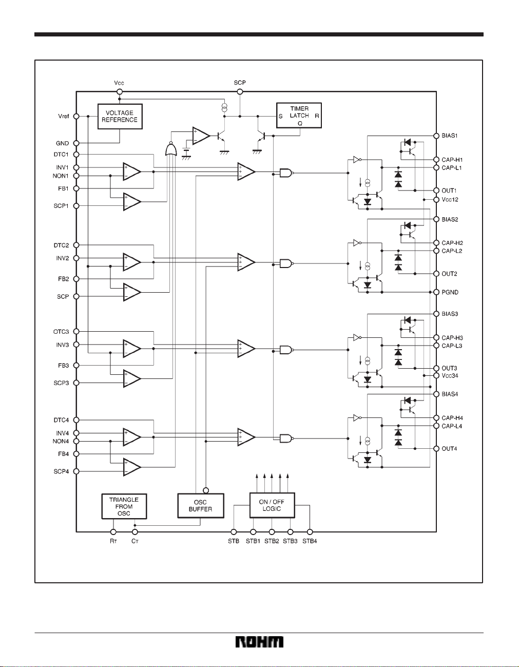
The BA9737KV is a 4-channel controller that includes all of the circuits required to construct a switching regulator. The
circuits on the chip include a triangular-wave oscillator, a reference voltage circuit, an error amplifier , a PWM comparator,
a pseudo-totem-pole driver, and a short-circuit protection circuit.
Applications
Camcoders and digital still cameras etc.
Features
1) The totem-pole driver can directly drive power transistors, and the on current can be set to the rating current using an external resistor.
For the off current, the peak current can be set using
an external capacitor.
2) Output cutoff circuit (timer latch type) for overload
protection.
3) Channels 2 and 3 are supplied using the internal reference voltage, and use a positive voltage only.
Channels 1 and 4 are general-purpose channels,
and all inputs are externally available.
4) Channels can be switched off individually or all together (STB and STB1 to STB4).
5) Dead-time control is provided for all channels, and
duty limits can be used.
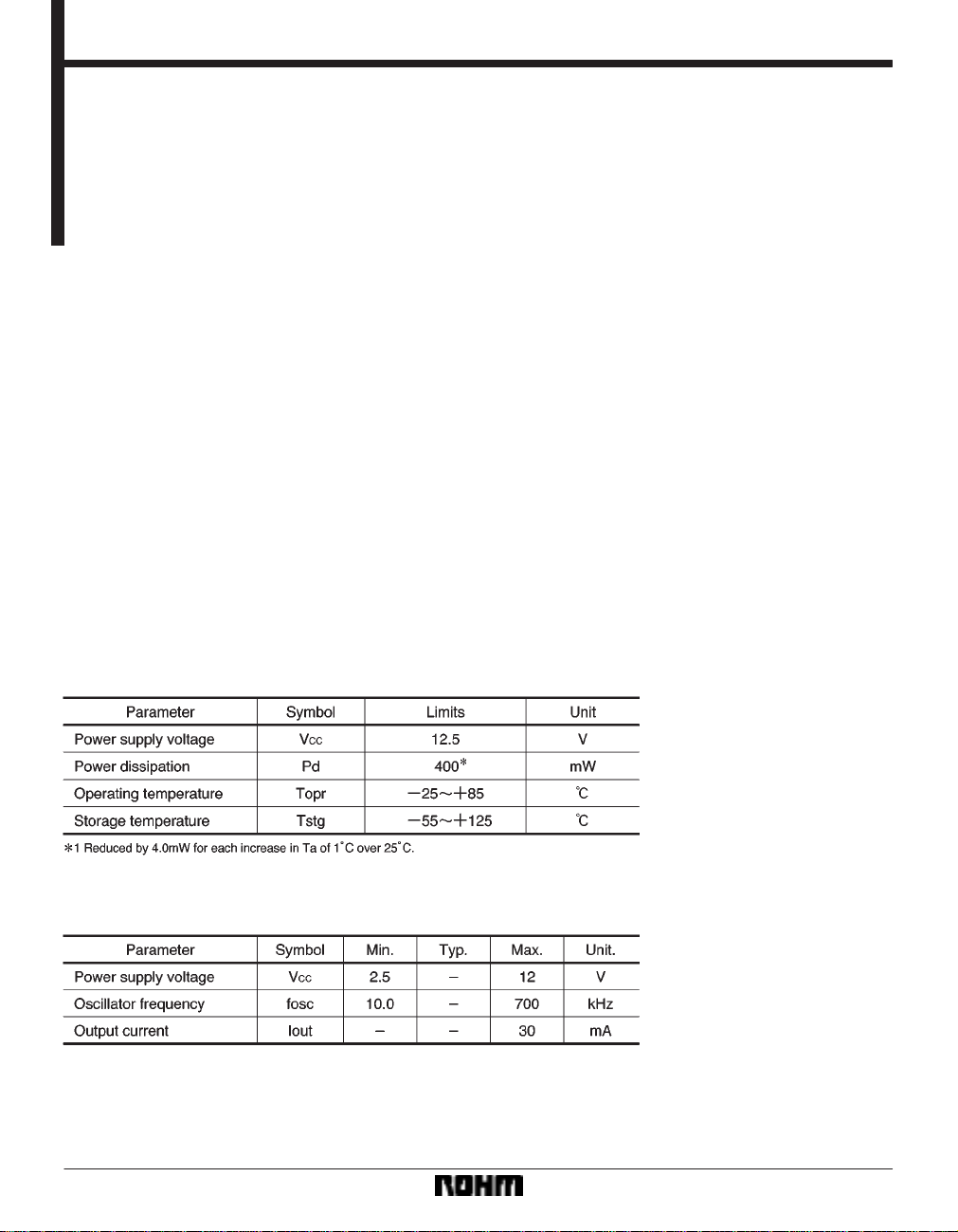
Absolute maximum ratings (Ta = 25C)
Recommended operating conditions (Ta = 25C)
412
Page 2
Regulator ICs BA9737KV
Block diagram
413
Page 3

Regulator ICs BA9737KV
Pin assignments
Pin descriptions
414
Page 4

Regulator ICs BA9737KV
Electrical characteristics (unless otherwise noted, Ta = 25C, VCC = 6.0V, fosc = 0.45MHz, STB,
STB1 to STB4 = 5V)
415
Page 5

Regulator ICs BA9737KV
Operation notes
(1) Use short and wide wiring tracks for the power supply and ground to keep the mutual impedance as small
as possible, and use inductors and capacitors to keep
ripple to a minimum.
(2) Great care has been paid to the quality of this component. However, if the absolute maximum ratings for
temperature and applied voltage are exceeded, the IC
may be destroyed.
Since it is not possible to predict whether it will be in short
mode or open mode if the IC is destroyed, if there is a
chance that the maximum ratings of the IC will be exceeded, use appropriate physical protective measures
(fuses etc.).
External dimensions (Units: mm)
(3) Set the dead-time input voltage to 0.58V or more.
(4) This IC does not use an internal circuit to generate
the output on peak current, so we recommend that you
connect capacitors to each end of R
erate the on peak current (after taking power dissipation
and efficiency into consideration). In this case, there is a
possibility that the output waveform may become unstable due to the current impedance, so we recommend that
you connect resistors (of about 100Ω to 500Ω) in series
with the off peak capacitors.
BIAS to externally gen-
416
 Loading...