

Page 1
Motor driver ICs
Reversible motor driver
BA6246N / BA6247 / BA6247N / BA6247FP-Y
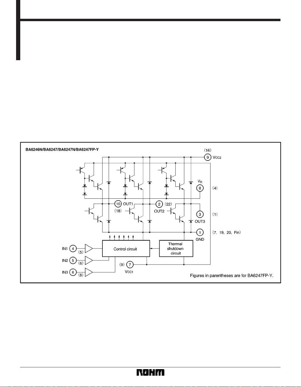
The BA6246N, BA6247, BA6247N and BA6247FP-Y are monolithic ICs incorporating two reversible-motor drivers. The
ICs differ in the control logic and output mode.
Features
1) Two reversible-motor drivers in each unit.
2) Built-in thermal shutdown circuit.
3) Output voltage can be set arbitrarily.
Block diagram
4) Available in a compact SIP10pin package
(BA6246N, BA6247N) or a HSIP10pin package with
radiation fins (BA6247).
5) Available in a HSOP25pin surface-mount package
(BA6247FP-Y).
498
Page 2
Motor driver ICs BA6246N / BA6247 / BA6247N / BA6247FP-Y
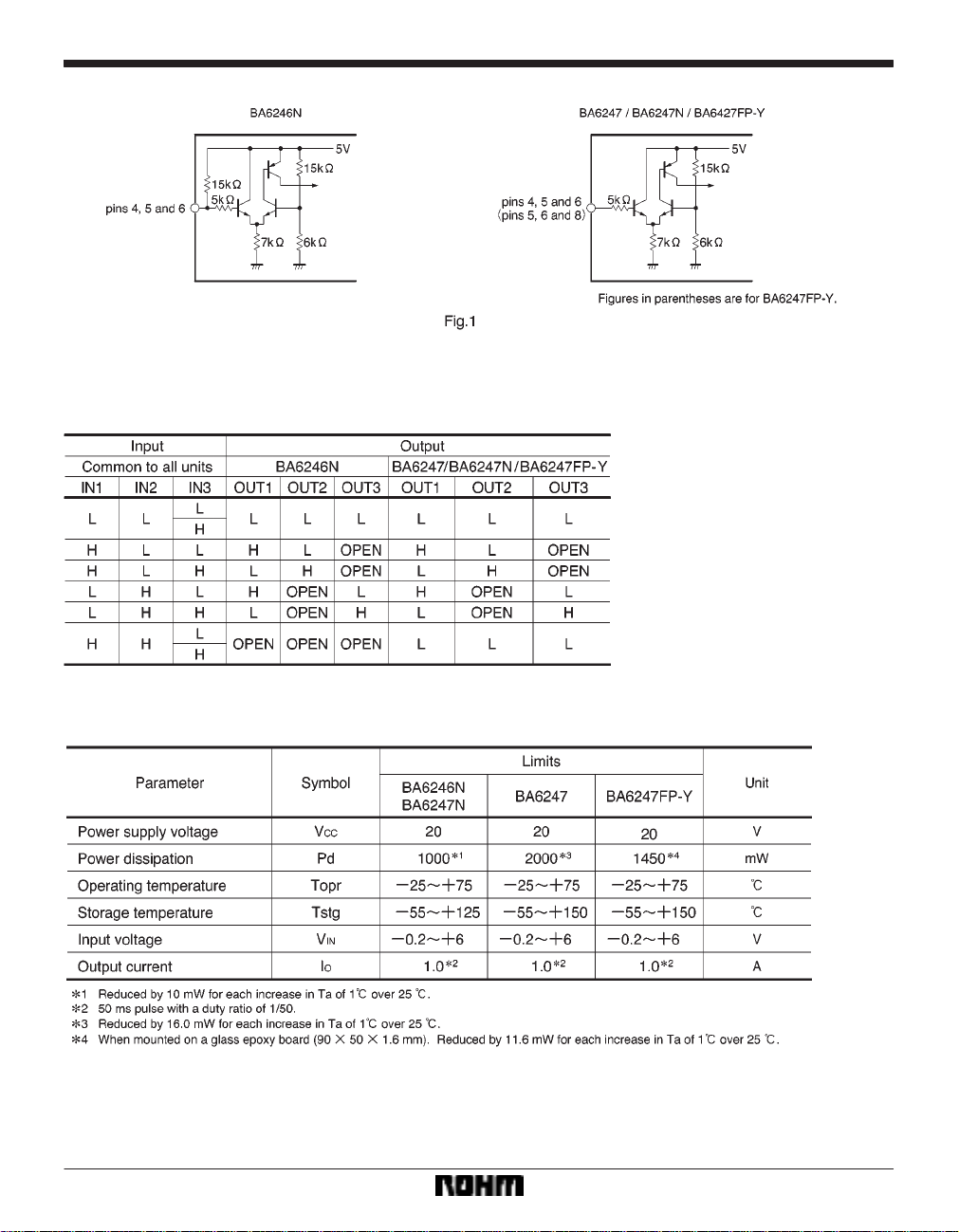
FControl pin equivalent circuits
FInput / output truth table
FAbsolute maximum ratings (Ta = 25_C)
499
Page 3
Motor driver ICs BA6246N / BA6247 / BA6247N / BA6247FP-Y
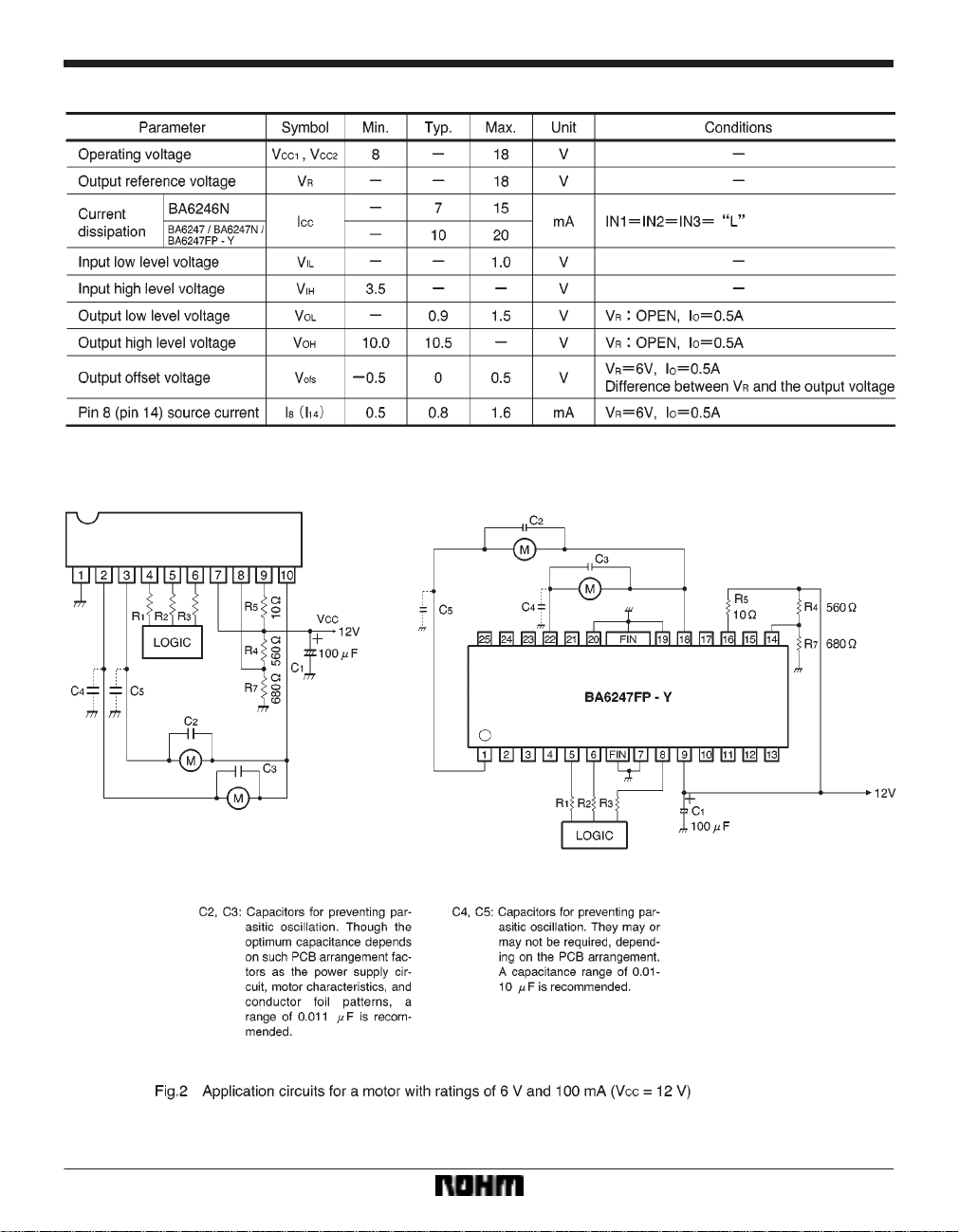
FElectrical characteristics (unless otherwise noted, Ta = 25_C and VCC = 12V)
FApplication examples
500
Page 4

Motor driver ICs BA6246N / BA6247 / BA6247N / BA6247FP-Y
FOperation notes
(1) Input conditions
(1) The input threshold voltage is positively correlated
with temperature as expressed by :
∆V
IH
∆T
∆V
∆T
2.8mV / _C
IL
1.6mV / _C (Typ.)
(2) The input pins of the BA6246N are pulled up through
a resistance of about 15kΩ (see Fig. 1). To secure the
LOW level input, the interface to these pins should have
a current-sink capability of at least 700µA
(5V / 15kΩ2).
(3) The maximum input voltage is 6V. Make sure that the
input will not exceed this value. Also when the voltage
V
CC is not applied to the IC, do not apply voltages to the
input pins.
(2) Changes in motor direction
When reversing the rotational direction of a motor, make
sure to go through the brake or open mode in-between
the opposite directions.
The duration of brake mode should be more than the
braking time, which is defined by the time required for the
potential of the LOW level output pin to become less than
the ground potential by the electromotive force generated when the mode is switched from rotation to brake.
The duration of open mode should be 1 ms or more.
(3) Due to the effects of capacitors C
2C5, the motor
that is not being driven could be momentarily driven during mode switching. Check for this problem when designing your application.
(4) It is recommendable to arrange your design so that
voltage rises at V
power, and voltage falls at V
CC1 prior to VCC2 when turning on the
CC1 after VCC2 when turning
off the power.
(5) Thermal shutdown circuit
When the thermal shutdown circuit is activated, the outputs are left OPEN. The circuit is activated when the IC
junction temperature rises above 170_C. The temperature difference between the activation and deactivation
settings is about 30_C.
(6) The quality of these products have been carefully
checked; however, use of the products with applied voltages, operating temperatures, or other parameters that
exceed the absolute maximum rating given may result in
the damage of the IC and the product it is used in. If the
IC is damaged, the short mode and open modes cannot
be specified, so if the IC is to be used in applications
where parameters may exceed the absolute maximum
retings, then be sure to incorporate fuses, or other physical safety measures.
(7) Back-rush voltage
Depending on the ambient conditions, environment, or
motor characteristics, the back-rush voltage may fluctuate. Be sure to confirm that the back-rush voltage will not
adversely affect the operation of the IC.
(8) Large current line
Large currents are carried by the motor power supply and
motor ground for these ICs. Therefore, the layout of the
pattern of the PC board and the constants of certain parameters for external components, such as the capacitor
between the power supply and ground, may cause this
large output current to flow back to the input pins, resulting in output oscillation or other malfunctions. T o prevent
this, make sure that the PC board layout and external circuit constants cause no problems with the characteristics of these ICs.
(9) Power dissipation
The power dissipation will fluctuate depending on the
mounting conditions of the IC and the ambient environment. Make sure to carefully check the thermal design of
the application where these ICs will be used.
(10) Power consumption
The power consumption by the IC varies widely with the
power supply voltage and the putput current. Give full
consideration to the power dissipation rating and the
thermal resistance data and transient thermal resistance
data, to provide a thermal design so that none of the ratings for the IC are exceeded.
(11) ASO
Make sure that the output current and supply voltage do
not exceed the ASO values.
(12) In-rush current
There are no circuits built into these ICs that prevent inrush currents. Therefore, it is recommended to place a
current limiting resistor or other physical countermeasure.
(13) Factors regarding the thermal, power supply, and
motor conditions
If the potential of the output pin sways greatly and goes
below the potential of ground, the operation of the IC may
malfunction or be adversely affected. In such a case,
place a diode between the output and ground, or other
measure, to prevent this.
501
Page 5

Motor driver ICs BA6246N / BA6247 / BA6247N / BA6247FP-Y
Power dissipation curves
Electrical characteristic curves
502
Page 6

Motor driver ICs BA6246N / BA6247 / BA6247N / BA6247FP-Y
External dimensions (Units: mm)
503
 Loading...