

Page 1
General Features
The ATVaultIC200 is an ASSP designed to secure various systems against counterfeiting, cloning or identity theft. It is a hardware security module that can be used in
many applications such as anti-cloning, access control or hardware protection.
Cryptographic Services Cryptographic Algorithms
• Digital Signature
• Encryption / Decryption
• Message Digest
• Key Wrapping / Unwrapping
• HOTP One-Time Password Generation
• True Random Number Generation
Software Features Memory
• FIPS 140-2 Identity-based authentication
using password, Secure Channel
Protocol (SCP02 / SCP03)
• Rights Management (Administrator,
Approved User, Non-approved User...)
• Embedded Dynamic FAT12 File System
• DES / 3DES
• AES 128/192/256 bits
• EEPROM 4 Kbytes (for user)
• Write Endurance 100 Kcycles
• Data Retention 10 Years
• 2ms Program + 2ms Erase
VaultICTM
Family
ATVaultIC200
Technical
Datasheet
Communication Packages
• Hi gh Speed Slave SPI Serial Interface,
ATMEL Proprietary Protocol
• I²C (Two Wire Interface), ATMEL
Proprietary Protocol
• ISO7816 UART using T=0 or T=1
Protocols
Hardware Platform Certifications
• SecureAVR
• Hardware Random Number Generator
• Hardware 3DES Crypto Accelerator (112bits keys)
For more details about the algorithms supported please refer to Table 2-1, “Supported
Algorithms table”, on page 8.
®
8-/16-bit RISC CPU
• 8-DFN (RoHS compliant)
•8-SOIC (RoHS compliant)
• EAL4+ Certification
• FIPS 140-2 Security Level 3
TPR0460AX–SMS–02/10
Page 2

Preliminary
This document is the complement to the “AT98SO/VaultIC Generic Datasheet” [1](TPR0395X-
Available under Non-Disclosure Agreement only) for the ATVaultIC200. It only documents the
values and set of features specific to this product.
2
ATVaultIC200
TPR0460AX–SMS–02/10
Page 3

1. Overview
1.1 Tampering resistance
The proven technology used in ATVaultIC200 security modules is already widespread and used
in national ID/health cards, e-passports, bank cards (storing user Personal Identification Number, account numbers and authentication keys among others), pay-TV access control and cell
phone SIM cards (allowing the storage of subscribers’ unique ID, PIN code, and authentication
to the network), where cloning must definitely be prevented. More than one billion of Secure
Microcontrollers addressing all these applications have been already sold by Atmel and successfully implemented in many secure systems.
Atmel’s security modules will advantageously replace complex and expensive proprietary antitampering protection system. Their advantages include low cost, ease of integration, higher
security and proven technology.
They are designed to keep contents secure and avoid leaking information during code execution. While on regular microcontrollers, measuring current consumption, radio emissions and
other side channels attacks may give precious information on the processed data or allow the
manipulation of the data. Atmel’s secure microcontrollers’ security features include voltage, frequency and temperature detectors, illegal code execution prevention, tampering monitors and
protection against side channel attacks and probing. The chips can detect tampering attempts
and destroy sensitive data on such events, thus avoiding data confidentiality being
compromised.
ATVaultIC200
These features make cryptographic computations secure in comparison with regular microcontrollers whose memories can be easily duplicated. It is much safer to delegate cryptographic
operations and storage of secret data (keys, identifiers, etc.) to an Atmel secure microcontroller.
1.2 Authentication capability
The methods to authenticate humans are generally classified into three cases: physical attribute
(e.g. fingerprint, retinal pattern, facial scan, etc.), security device (e.g. ID card, security token,
software token or cell phone) and something the user knows (e.g. a password/passphrase or a
personal identification number).
To fight against identity theft, the multi-factor authentication is a stronger alternative to the classical login/password authentication (called weak authentication). It combines two or more
authentication methods (often a password combined with a security token). Two-factor systems
greatly reduce the likelihood of fraud by requiring the presence of a physical device used
together with a password. If the physical device is lost or the password is compromised, security
is still intact. NIST’s authentication guideline [2] can be referred to for further details.
Multi-factor authentication requires a strong authentication. Anticloning is safely implemented
through one-way or mutual strong authentication. Various authentication protocols exist (as
specified in ISO9798-2 [3] or FIPS196 [4]), but the main method is the challenge response
authentication:
1. The authenticator sends a challenge (e.g. a random number) to the equipment that must be
authenticated (“the claimant”).
2. The claimant computes a digital signature of the combination of this challenge with an
optional identifier, using a private or secret key. The requested signature is then returned to
the authenticator.
TPR0460AX–SMS–02/10
3
Page 4

1.3 Secure stor age
1.4 Flexibility
3. The authenticator checks the signature using either the same secret key or the public key
associated to the claimant’s private key and decides whether the claimant is authorized or
not based on the signature verification result.
This strong authentication method requires storing secret data. Pure software multi-factor solutions are thus not reliable.
If sensitive data is stored in files on a hard disk, even if those files are encrypted, the files can be
stolen, cloned and subjected to various kinds of attacks (e.g. brute force or dictionary attack on
passwords). Therefore secure microcontrollers-based hardware tokens are a must. Placing
secrets outside the computer avoids risking exposure to malicious software, security breaches in
web browsers, files stealing, etc.
The ATVaultIC200 product features:
• Various communication interfaces including SPI (Serial Protocol Interface), I
Integrated Circuit Bus) and ISO7816 SmartCard interface.
• Low pin count (Reset, Vcc, GND, and communication interface specific pins) making
integration into an existing board simple. ATVaultIC200 modules are available in small
packages (SOIC8 or DFN8) to fit into the most size-constrained devices.
• Low power consumption, in order to extend battery life in portable devices and low-power
systems. ATVaultIC200 devices consume less than 200μA in standby mode, and only 10 mA
during CPU-intensive operations depending on the required action.
• Embedded firmware that provides advanced functions:
– Secure storage: a fully user-defined non-volatile storage of sensitive or secret data.
– Identity-based authentication with user, administrator and manufacturer roles
supported.
– Administration mode to manage user authentication data and security features
– Manufacturer mode to initialize the file system content and module parameters.
– Cryptographic command set to perform cryptographic operations using keys and
data from the file system including: authentication, digital signature,
encryption/decryption, hash, one-time password generation and random generation.
– Public domain cryptographic algorithms such as DES, 3DES, AES, MAC using DES,
3DES or AES
– Cryptographic protocols such as secret-key unilateral or mutual authentication [3].
– Secure Channel Protocol using 3DES or AES.
– Robust communication protocol stacked over the physical communication
interfaces.
–Starter Kit.
Atmel’s application note [5] presents examples of efficient and cost effective IP protection applications utilizing secure chips in various embedded systems.
2
C (Inter
4
ATVaultIC200
TPR0460AX–SMS–02/10
Page 5
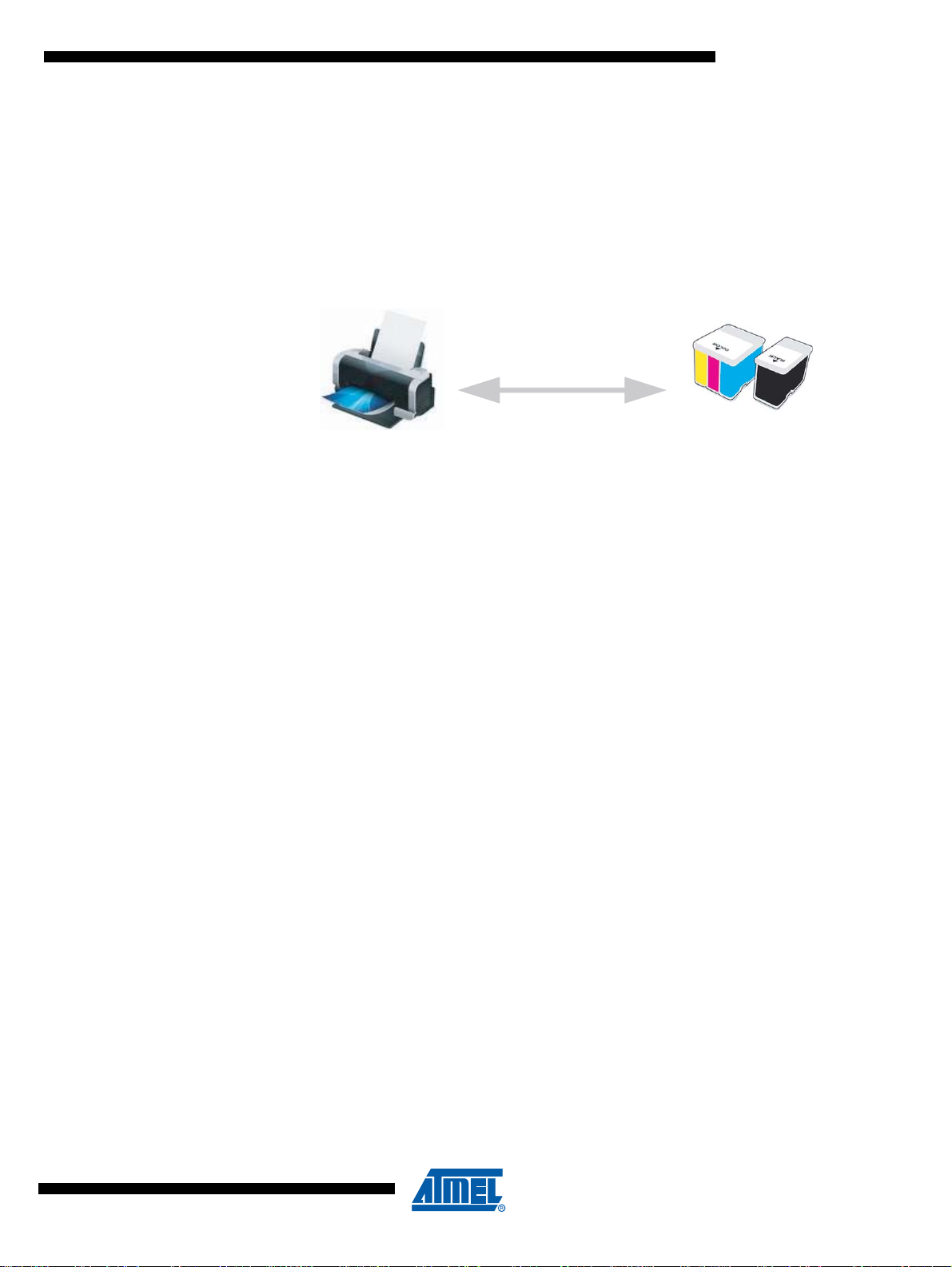
1.5 Typical application
Authentication
Printer
Ink cartridges
The ATVaultIC200 is a turnkey solution that combines powerful cryptographic capabilities and
secure data storage. Ink Cartridge, Access Control or Smart meters are some examples of use
of the ATVaultIC200.
Below is described an example of an ATVaultIC200 product used in a typical application : Ink
Cartridge anti-cloning.
Figure 1-1. Ink Cartridge anti-cloning application scheme
ATVaultIC200
For more details about the architecture, please refer to the Application Note ”How to protect
Intellectual Properties using VaultIC Security Modules”[5].
1.6 Ordering Information
1.6.1 Legal
A Non-Disclosure Agreement must be signed with ATMEL.
An Export License for cryptographic hardware/software must be granted.
1.6.2 Quotation and Volume
For the minimum order of quantity and the annual volume, please contact your local ATMEL
sales office.
TPR0460AX–SMS–02/10
5
Page 6
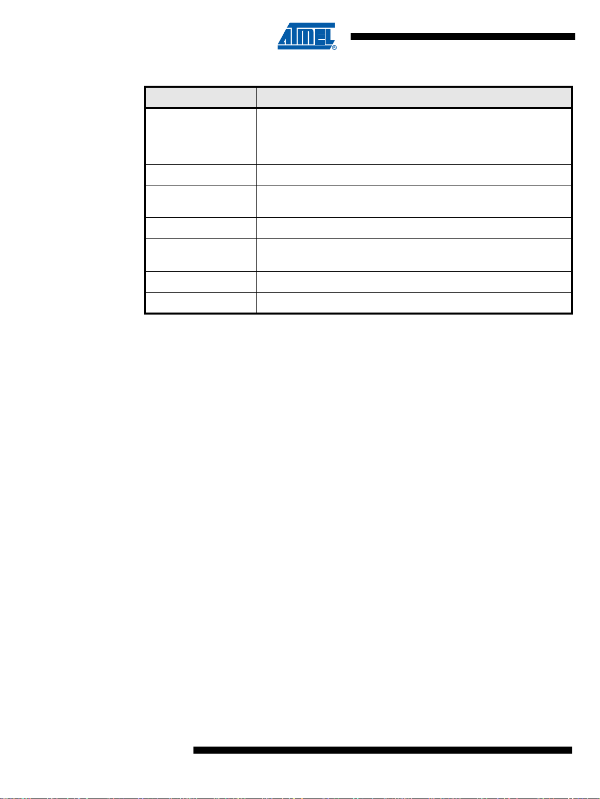
1.6.3 Part Number
Reference Description
ATVaultIC200-xxx-P xxx : Chip Personalization Number*
P = Z : DFN8 Package
R : SOIC8 Package
ATVAULTIC-STK02-200R Starter Kit for ATVaultIC200 in SOIC8 package - SPI/I2C configuration
1.6.4 Starter Kit
ATVAULTIC-STK12-200R
ATVAULTIC-STK02-200Z Starter Kit for
ATVAULTIC-STK12-200Z
ATVAULTIC-STK03-200R Starter Kit for ATVaultIC200 in SOIC8 package - ISO7816 configuration
ATVAULTIC-STK03-200Z Starter Kit for
Starter Kit for
(no SPI/I2C adapter inside)
Starter Kit for
(no SPI/I2C adapter inside)
ATVaultIC200 in SOIC8 package - SPI/I2C configuration
ATVaultIC200 in DFN8 package - SPI/I2C configuration
ATVaultIC200 in DFN8 package - SPI/I2C configuration
ATVaultIC200 in DFN8 package - ISO7816 configuration
* For more details about the Chip Personalization Number, please contact your local ATMEL
sales office.
The ATVaultIC Starter Kit provides an easy path to master the cryptographic and secure data
storage features of the ATVaultIC secure modules. The content is :
• ATVaultIC200 samples with 1 dedicated test socket
• 1 generic USB to SPI / I²C / ISO7816 adapter
• 1 CD-ROM containing a support documentation set (getting started, application notes,
reference design), some demo applications to get an insight into the ATVaultIC features, the
”VaultIC Manager” tool to design the file system and to personalize samples, a hardware
independent cryptographic API with source code.
1.6.5 Demo Kit
6
ATVaultIC200
TBD
TPR0460AX–SMS–02/10
Page 7

1.7 Software and Hardware Architecture
Crypto
services
( MAC,Signature,…)
Application
management
&
Data storage
Administration
services
CRYPTO
APPLICATION
ADMINISTRATION
APPLICATION
TDES
EEProm
RAM
HS
SPI
Device
Crypto Library
CRC
(File System) (Keymanagement)
Memory
Management
Comm unication
Stack
SPI / I2C / ISO7816
VaultIC200 Hardware
I2C
secureAVR
CORE
Power
Hardware
Security
Management
T=0 T=1
(AES...)
The ATVaultIC200 software architecture is as exposed on the diagram below.
Figure 1-2. Software and Hardware Architecture
ATVaultIC200
TPR0460AX–SMS–02/10
7
Page 8

2. Detailed Features
2.1 Communication Interfaces
The ATVaultIC200 embeds the following communication interfaces:
• High Speed SPI : up to 16 Mbps
• I²C : up to 400 kbps
• ISO7816 : up to 625 kbps
2.2 Security Mech anisms
The table below summarizes the cryptographic algorithms, and their identifiers, supported by the
ATVaultIC200.
Table 2-1. Supported Algorithms table
Cryptographic Services Supported Algorithms Algo Identifier
• Generic:
ISO/IEC 9798-2 / FIPS 196 unilateral
authentication protocol
ISO/IEC 9798-2 mutual authentication
protocol
Strong Authentication
• Password authentication
-
CMAC
(Cipher-based Message
Authentication Codes)
HMAC
(Hash-base d Message Authen-
tication Codes)
• Global Platform v2.2 Secure Channel 02
(SCP02) using 3DES
• Global Platform v2.2 Secure Channel 03
(SCP03) using AES
• ISO/IEC 9797-1 CBC-MAC algorithm 1
using 3DES with 112-bit keys
• ISO/IEC 9797-1 CBC-MAC algorithm 3
using DES with 56-bit keys
• NIST SP 800-38B AES CMAC
• FIPS 198 HMAC with SHA-1 or SHA-256 • ALG_HMAC
• ALG_MAC_ISO9797_ALG1_3DES_
EDE
• ALG_MAC_ISO9797_ALG3_DES
• ALG_CMAC_AES
-
8
ATVaultIC200
TPR0460AX–SMS–02/10
Page 9

ATVaultIC200
Cryptographic Services Supported Algorithms Algo Identifier
Block Ciphering:
Message Encryption
HOTP - One-Time Password
Generation
Message Digest
•DES
•3DES-EDE
•3DES-EEE
•AES
Block chaining modes:
•ECB
•CBC
•OFB
•CFB
Padding methods:
• No padding
• Method 1
• Method 2
• PKCS 5
• PKCS 7
• FIPS 198 HMAC algorithm with SHA1
digest
•SHA-1
• SHA-224
• SHA-256
• ALG_DES
• ALG_3DES_EDE
• ALG_3DES_EEE
• ALG_AES
• CHA_ECB
•CHA_CBC
•CHA_OFB
•CHA_CFB
•PAD_NONE
• PAD_METHOD_1
• PAD_METHOD_2
• PAD_PKCS5
• PAD_PKCS7
• ALG_HOTP
• ALG_SHA1
• ALG_SHA224
• ALG_SHA256
Random Number Generation • FIPS 140-2 LVL3 using 3DES -
TPR0460AX–SMS–02/10
9
Page 10

3. Product Characteristics
Caution
!
3.1 Command Timings (T=25°C)
The table below includes only the ATVaultIC200 internal process. Communication protocol overhead and device-side process are excluded.
Table 3-1. Command Timings table
Command
(or batch of commands)
Encryption / Decryption
Encryption / Decryption
Encryption / Decryption
Signature / Verification MAC DES algo 3 padding M2, 258 bytes data TBD ms
Signature / Verification MAC DES algo 1 padding M2, 258 bytes data TBD ms
Signature / Generation MAC DES algo 3 padding M2, 258 bytes data TBD ms
Signature / Generation MAC DES algo 1 padding M2, 258 bytes data TBD ms
DES-ECB, 258 bytes data TBD ms
3DES-ECB, 258 bytes data TBD ms
AES TBD ms
Context Min. Typ. Max. Unit
10
ATVaultIC200
TPR0460AX–SMS–02/10
Page 11

ATVaultIC200
3.2 Maximum Ratings
Table 3-2. Absolute Maximum Ratings
Notes: 1. Stresses beyond those listed under “Absolute Maximum Ratings” may cause permanent dam-
(1)
Symbol Parameter Min. Max. Unit
V
CC
V
IN
T
A
E
EEPROM
V
DataRetention
Supply Voltage -0.3 7.5 V
Input Voltage VSS-0.3 VCC+0.3 V
Operating Temperature -25 +85 °C
EEPROM Endurance for
write/erase cycles
500 000
(2)
EEPROM Data Retention Virgin 10 Years
ESD Electrostatic Discharge (HBM) 4 kV
Latch-up +/- 200 mA
age to the device. This is a stress rating only and functional operation of the device at these or
other conditions beyond those indicated in the operational sections of this specification is not
implied. Exposure to absolute maximum rating conditions for extended periods may affect
device reliability.
2. Depends on conditions. Please refer to “EEPROM Reliability & Qualification Specification”
(PE/SPEC/032).
cycles
3.3 AC/DC Characteristics (2.7V - 5.5V range; T= -25°C to +85°C)
Table 3-3. AC/DC Characteristics (2.7V - 5.50V range; T= -25°C to +85°C)
Symbol Parameter Condition Min. Typ. Max. Unit
V
Supply Voltage 2.7 5.5 V
CC
V
Ground
SS
V
V
T
T
Voltage Monitor: high level detection 5.5 V
MAX
Voltage Monitor: low level detection 3V, 5V 2.7 V
MIN
Temperature Monitor: high level
MAX
detection
Temperature Monitor: low level
MIN
detection
Input High Voltage -
V
IH
I/Os,ISOCLK,RST, MISO,MOSI
Input Low Voltage -
V
IL
I/Os,ISOCLK,RST, MISO,MOSI
Leakage High Current -
I
IH
I/Os,ISOCLK,RST, MISO,MOSI
VIN = V
IH
85 °C
-25 °C
0.7*V
CC
-0.3 0.2*V
VCC+0.3 V
CC
-10 10 μA
V
TPR0460AX–SMS–02/10
Leakage Low Current -
I
IL
I/Os,ISOCLK,RST, MISO,MOSI
= V
V
IN
IL
-40 10 μA
11
Page 12

Symbol Parameter Condition Min. Typ. Max. Unit
V
OL
V
OH
R
f
SCK
T
SCKrising
T
SCKfalling
I
cc
Output Low Voltage - I/O0,I/O1
Output Low Voltage - MISO, MOSI
Output High Voltage - I/O0,I/O1
Output High Voltage - MISO, MOSI
Pin Pull-up I/O0, RST,I/O1,MISO,
I/O
MOSI
SPI Clock (Input)
SCK rising to MISO delay
SCK falling to MISO delay
Typical Current at 25°C
I
OL
=1mA
0
0
IOH = 1mA 0.7*V
CC
0.08*V
0.15*V
V
CC
CC
CC
220 KOhm
C
=20pF
out
DMA On
C
=20pF
out
Slave Mode
=20pF
C
out
Slave Mode
20 MHz
13 μs
13 μs
- Chip in low power mode:
•200μA (Clock=1MHz)
•200μA when no clock running
- Chip awaken, no crypto running:
• 6mA when external clock supplied (5MHz)
• 10mA when no external clock is supplied (CLK
signal in high state)
- Additional consumption during DES computations:
• 4mA when external clock supplied
• 10mA when no external clock is supplied (CLK
signal in high state)
V
V
12
ATVaultIC200
TPR0460AX–SMS–02/10
Page 13

3.4 Timings
3.4.1 I²C Timings
ATVaultIC200
The table below describes the requirements for devices connected to the I²C Bus. The
ATVaultIC200 I²C Interface meets or exceeds these requirements under the noted conditions.
Timing symbols refer to Figure 3.4.2.
Table 3-4. I²C Requirements
Symbol Parameter Condition Min Max Unit
SCL
SDA
t
SU;STA
t
r
t
of
f
SCL
t
HD;STA
t
LOW
t
HIGH
t
SU;STA
t
HD;DAT
t
SU;DAT
t
SU;STO
t
BUF
Rise Time for both SDA and SCL TBD TBD ns
Output Fall Time from V
SCL Clock Frequency TBD 100 kHz
Hold Time (repeated) START Condition TBD TBD μs
Low Period of the SCL Clock TBD TBD μs
High period of the SCL clock TBD TBD μs
Set-up time for a repeated START condition TBD TBD μs
Data hold time TBD TBD μs
Data setup time TBD TBD ns
Setup time for STOP condition TBD TBD μs
Bus free time between a STOP and START
condition
Figure 3-1. I²C Timings
t
HIGH
t
HD;DAT
t
HD;STA
t
of
t
LOW
IHmin
t
LOW
to V
ILmax
t
SU;DAT
TBD TBD ns
TBD TBD μs
t
r
t
SU;STO
TPR0460AX–SMS–02/10
t
BUF
13
Page 14

3.4.2 SPI Timings
MISO
(Data Output)
SCK
(CPOL = 1)
MO SI
(Data Input)
SCK
(CPOL = 0)
SS
MSB LSB
LSBMSB
...
...
10
11 11
1213 14
17
15
9
X
16
The table below describes the requirements for devices connected to the SPI. The
ATVaultIC200 SPI meets or exceeds these requirements under the noted conditions.
See Figure 3-2 for details.
Table 3-5. SPI Timing Parameters
See figure Description Condition Min Typ Max Unit
9SS
10 SCK period TBD ns
11 SCK high/low TBD ns
12 Rise/Fall time TBD ns
13 Setup TBD ns
14 Hold TBD ns
15 SCK to out TBD ns
16 SCK to SS
17 SS
high to tri-state TBD ns
18 SS
Figure 3-2. SPI Timings
low to out TBD ns
high TBD ns
low to SCK TBD ns
14
ATVaultIC200
TPR0460AX–SMS–02/10
Page 15

3.5 Connexions for Typical Application
C1
VCC
C2
R1
RST
SCL
SDA / SPI_SEL
SCL
SDA
RESET
VCC
VCC
ATVaultIC200
HOST
GND
R2
VCC
C1
VCC
C2
RST
RESET
VCC
VCC
ATVaultIC200
HOST
GND
SPI_SEL
MISO
MOSI
SCK
MOSI
MISO
SCK
SS
SS
C1
C2
RST
I/O0
CLK
I/O0
CLK
RESET
VCC
CVCC
ATVaultIC200
SC
READER
GND
R1
VCC
GND
Figure 3-3. ATVaultIC200 connexions for I²C typical application
For the address selection of the VaultIC200 in I²C configuration, please refer to the
“AT98SO/VaultIC Generic Datasheet”.
Figure 3-4. ATVaultIC200 connexions for SPI typical application
ATVaultIC200
TPR0460AX–SMS–02/10
Figure 3-5. ATVaultIC200 connexions for ISO7816 typical application
15
Page 16

Table 3-6. External components, Bill of Materials
Configuration Reference Description Typ.Value Comment
2.2 k
Ω Recommended
4.7 μF Recommended
10 nF
4.7 μF Recommended
10 nF
20 k
Ω usually on reader side
4.7 μF usually on reader side
10 nF
Recommended
Recommended
usually on reader side
2
I
C
SPI
ISO7816
R1, R2 Pull-Up Resistors
C1 Power Supply Decoupling Capacitors
C2 Power Supply Decoupling Capacitors
C1 Power Supply Decoupling Capacitors
C2 Power Supply Decoupling Capacitors
R1 Pull-Up Resistor
C1 Power Supply Decoupling Capacitors
C2 Power Supply Decoupling Capacitors
3.6 Pin & Package Configuration
3.6.1 Pin Configuration Table 3-7. Pin List Configuration
Pin #
Designation
SOIC8 DFN8
Description
RST
VCC
MISO
MOSI
SCL / SS
IO0 / SDA / SPI_SEL
CLK / SCK
GND
66
77
88
11
33
44
55
22
CPU reset
Power supply
SPI Master Input Slave Output
SPI Master Output Slave Input
I²C SCL / SPI Slave Select
ISO7816 I/O0 / I²C SDA / SPI/I²C selection PIN
ISO7816 CLK / SPI Master clock
Ground (reference voltage)
Others pins are not connected (do not connect to GND).
When communicating with SPI, all pins not used for SPI must not be connected (do not connect
to GND).
16
ATVaultIC200
TPR0460AX–SMS–02/10
Page 17

3.6.2 Pinouts for packages SOIC8 and DFN8
ATVaultIC200
SOIC8
INDEX CORNER
MOSI
GND
1
2
3
4
8
7
6
5
MISO
VCC
RST
SCK / CLK
SCL / SS
SDA / SPI_SEL / IO0
2
3
1
4
8
7
6
5
ATVaultIC200
SPI_MISO
VCC
RST
SPI_CLK / ISO_CLK
SPI_MOSI
GND
SCL / SPI_SS
SDA / SPI_SEL / IO0
INDEX CORNER
Figure 3-6. Pinout ATVaultIC200 - Package SOIC8
Figure 3-7. Pinout ATVaultIC200 - Package DFN8
ATVaultIC200
TPR0460AX–SMS–02/10
17
Page 18

3.6.3 Packages characteristics
COMMON DIMENSIONS
(Unit of Measure = mm)
SYMBOL
MIN
NOM
MAX
NOTE
Notes: 1. This drawing is for general information only; refer to EIAJ Drawing EDR-7320 for additional information.
2. Mismatch of the upper and lower dies and resin burrs are not included.
3. It is recommended that upper and lower cavities be equal. If they are different, the larger dimension shall be regarded.
4. Determines the true geometric position.
5. Values b and C apply to pb/Sn solder plated terminal.
The standard thickness of the solder layer shall be 0.010 +0.010/-0.005 mm.
A 1.70 2.16
A1 0.05 0.25
b 0.35 0.48 5
C 0.15 0.35 5
D 5.13 5.35
E1 5.18 5.40 2, 3
E 7.70 8.26
L 0.51 0.85
?
0˚ 8˚
e 1.27 BSC 4
End View
Side View
e
b
A
A1
D
E
N
1
C
E1
?
L
Top View
Figure 3-8. SOIC-8 package characteristics
18
ATVaultIC200
TPR0460AX–SMS–02/10
Page 19

Figure 3-9. DFN-8 package characteristics
ATVaultIC200
TPR0460AX–SMS–02/10
19
Page 20

Definitions and abbreviations
3DES / TDES Triple DES algorithm
AES Advanced Encryption Standard algorithm as defined in FIPS PUB 197
APDU Application Protocol Data Unit as defined in ISO7816-3
Authentication An identification or entity authentication technique assures one party (the verifier), through acquisi-
tion of corroborative evidence, of both the identity of a second party involved, and that the second
(the claimant) was active at the time the evidence was created or acquired. (From Handbook of
Applied Cryptography)
ASSP Application Specific Standard Product
CBC Cipher Block Chaining method applied to block ciphers
CFB Cipher Feedback Register chaining method applied to block ciphers
CMAC Cipher-based Message Authentication Code
CPU Central Processing Unit
Cryptographic key A bit string used as a secret parameter by a cryptographic algorithm. To prevent a key from being
guessed, keys need to be generated truly randomly and contain sufficient entropy.
DES Data Encryption Standard algorithm as defined in FIPS PUB 46-3
Device Any CPU with master or slave capability
ECB Electronic Code Book chaining method applied to block ciphers
EEPROM Electrically Erasable Programmable Read-Only Memory
FAT File Allocation Table - file system from Microsoft
FIPS Federal Information Processing Standards
FIPS-approved An algorithm or technique that is specified or adopted in FIPS
HMAC Hash-based Message Authentication Code as defined in FIPS PUB 198
Host Entity that communicates (directly or not) with the device
HOTP HMAC-based One Time Password algorithm as defined in RFC 4226
ISO7816 Smart Card interface
MAC Message Authentication Code - A bit string of fixed length, computed by a MAC generation algo-
rithm, that is used to establish the authenticity and, hence, the integrity of a message.
Master The device that initiates and terminates a transmission. The Master also generates the clock for syn-
chronous interface.
NIST National Institute of Standards and Technology
NVM Non Volatile Memory (EEPROM, flash, …)
®
OFB Output Feedback Register chaining method applied to block ciphers
SCP Secure Channel Protocol as defined by GlobalPlatform
SHA Secure Hash Algorithm
20
ATVaultIC200
TPR0460AX–SMS–02/10
Page 21

ATVaultIC200
Slave The device addressed by a master
SPI Serial Protocol Interface
Strong Authentication Exchange of messages during which a claimant proves its identity to a verifier by demonstrating its
knowledge of a secret but without revealing it
2
TWI / I
C Two Wire Interface and Inter Integrated Circuit Bus respectively
TPR0460AX–SMS–02/10
21
Page 22

Referenced Documents
[1] ATMEL Corporation. AT98SO/VaultIC Generic Datasheet. TPR0395AX-July2009
(Availbale under Non-Disclosure Agreement signed with ATMEL).
[2] NIST SP 800-63 - Electronic Authentication Guideline - April 2006
[3] ISO9798 - 2 Entity Authentication - Part 2 : Mechanisms using symmetric encipherment
algorithms. July 1999
[4] FIPS PUB 196. Entity Authenticationusing public key cryptography. Feb 1997.
[5] Atmel Corporation. How to secure Intellectual Properties using VaultIC Security Mod-
ules. TPR453X-2010
22
ATVaultIC200
TPR0460AX–SMS–02/10
Page 23

Datasheet Revision History
Rev AX - 01 February 2010 : Initial Version
ATVaultIC200
TPR0460AX–SMS–02/10
23
Page 24

1 Overview ................................................................................................... 3
1.1 Tampering resistance ........................................................................................3
1.2 Authentication capability ....................................................................................3
1.3 Secure storage .................................................................................................. 4
1.4 Flexibility ............................................................................................................ 4
1.5 Typical application ............................................................................................. 5
1.6 Ordering Information .......................................................................................... 5
1.6.1 Legal ................................................................................................................. 5
1.6.2 Quotation and Volume ...................................................................................... 5
1.6.3 Part Number ......................................................................................................6
1.6.4 Starter Kit .......................................................................................................... 6
1.6.5 Demo Kit ...........................................................................................................6
1.7 Software and Hardware Architecture ................................................................. 7
2 Detailed Features ........................ ..... .... ..... ...............................................8
2.1 Communication Interfaces .................................................................................8
2.2 Security Mechanisms ........................................................................................8
3 Product Characteristics ........................................................................ 10
3.1 Command Timings (T=25°C) ........................................................................... 10
3.2 Maximum Ratings ............................................................................................ 11
3.3 AC/DC Characteristics (2.7V - 5.5V range; T= -25°C to +85°C) .....................11
3.4 Timings ............................................................................................................ 13
3.4.1 I²C Timings ......................................................................................................13
3.4.2 SPI Timings ..................................................................................................... 14
3.5 Connexions for Typical Application .................................................................15
3.6 Pin & Package Configuration ........................................................................... 16
3.6.1 Pin Configuration ............................................................................................ 16
3.6.2 Pinouts for packages SOIC8 and DFN8 .........................................................17
3.6.3 Packages characteristics ................................................................................18
24
ATVaultIC200
TPR0460AX–SMS–02/10
Page 25

ATVaultIC200
TPR0460AX–SMS–02/10
25
Page 26

Headquarters International
Atmel Corporation
2325 Orchard Parkway
San Jose, CA 95131
USA
Tel: 1(408) 441-0311
Fax: 1(408) 487-2600
Atmel Asia
Unit 01-05 & 16, 19/F
BEA Tower, Millennium City 5
418 Kwun Tong Road
Kwun Tong, Kowloon
Hong Kong
Tel: (852) 2245-6100
Fax: (852) 2722-1369
Product Contact
Web Site
www.atmel.com
Literature Requests
www.atmel.com/literature
Atmel Europe
Le Krebs
8, Rue Jean-Pierre Timbaud
BP 309
78054 Saint-Quentin-enYvelines Cedex
France
Tel: (33) 1-30-60-70-00
Fax: (33) 1-30-60-71-11
Technical Support
at98sc@atmel.com
Atmel Japan
9F, Tonetsu Shinkawa Bldg.
1-24-8 Shinkawa
Chuo-ku, Tokyo 104-0033
Japan
Tel: (81) 3-3523-3551
Fax: (81) 3-3523-7581
Sales Contact
www.atmel.com/contacts
Disclaimer: The information in this document is provided in connection with Atmel products. No license, express or implied, by estoppel or otherwise, to any
intellectual property right is granted by this document or in connection with the sale of Atmel products. EXCEPT AS SET FORTH IN ATMEL’S TERMS AND CO NDI-
TIONS OF SALE LOCATED ON ATMEL’S WEB SITE, ATMEL ASSUMES NO LIABILITY WHATSOEVER AND DISCLAIMS ANY EXPRESS, IMPLIED OR STATUTORY
WARRANTY RELATING TO ITS PRODUCTS INCLUDING, BUT NOT LIMITED TO, THE IMPLIED WARRANTY OF MERCHANTABILITY, FITNESS FOR A PARTICULAR
PURPOSE, OR NON-INFRINGEMENT. IN NO EVENT SHALL ATMEL BE LIABLE FOR ANY DIRECT, INDIRECT, CONSEQUENTIAL, PUNITIVE, SPECIAL OR INCIDENTAL DAMAGES (INCLUDING, WITHOUT LIMITATION, DAMAGES FOR LOSS OF PROFITS, BUSINESS INTERRUPTION, OR LOSS OF INFORMATION) ARISING OUT
OF THE USE OR INABILITY TO USE THIS DOCUMENT, EVEN IF ATMEL HAS BEEN ADVISED OF THE POSSIBILITY OF SUCH DAMAGES. Atmel makes no
representations or warranties with respect to the accuracy or completeness of the contents of this document and reserves the right to make changes to specifications
and product descriptions at any time without notice. Atmel does not make any commitment to update the information contained herein. Atmel’s products are not
intended, authorized, or warranted for use as components in applications intended to support or sustain life.
© 2009 Atmel Corporation. All rights reserved. Atmel
®
, logo and combinations thereof, Everywhere You Are® and others, are registered trade-
marks or trademarks of Atmel Corporation or its subsidiaries. Other terms and product names may be trademarks of others.
TPR0460AX–SMS–02/10
 Loading...