

Page 1

Features
• High-performance, Low-power AVR
– 130 Powerful Instructions - Most Single Clock Cycle Execution
– 32 x 8 General Purpose Working Registers
– Fully Static Operation
– Up to 8 MIPS Throughput at 8 MHz
– On-chip 2-cycle Multiplier
• Nonvolatile Program and Data Memories
• Self-programming In-System Programmable Flash Memory
– 16K Bytes with Optional Boot Block (256 - 2K Bytes)
Endurance: 1,000 Write/Erase Cycles
– Boot Section Allows Reprogramming of Program Code without External
Programmer
– Optional Boot Code Section with Independent Lock Bits
– 512 Bytes EEPROM
Endurance: 100,000 Write/Erase Cycles
– 1024 Bytes Internal SRAM
– Programming Lock for Software Security
• Peripheral Features
– Two 8-bit Timer/Counters with Separate Prescaler and Compare Mode
– One 16-bit Timer/Counter with Separate Prescaler, Compare Mode, and Capture
Mode
– Real Time Clock with Separate Oscillator and Counter Mode
– Three PWM Channels
– 8-channel, 10-bit ADC
– Byte-oriented 2-wire Serial Interface
– Programmable Serial UART
– Master/Slave SPI Serial Interface
– Programmable Watchdog Timer with Separate On-chip Oscillator
– Analog Comparator
• Special Microcontroller Features
– Power-on Reset and Programmable Brown-out Detection
– Internal Calibrated RC Oscillator
– External and Internal Interrupt Sources
– Four Sleep Modes: Idle, ADC Noise Reduction, Power Save, and Power-Down
• Power Consumption at 4 MHz, 3.0V, 25°C
– Active 50 mA
– Idle Mode 1.9 mA
– Power-down Mode < 1 µA
• I/O and Packages
– 32 Programmable I/O Lines
– 40-pin PDIP and 44-pin TQFP
• Operating Voltages
– 2.7 - 5.5V (ATmega163L)
– 4.0 - 5.5V (ATmega163)
• Speed Grades
– 0 - 4 MHz (ATmega163L)
– 0 - 8 MHz (ATmega163)
®
8-bit Microcontroller
8-bit
Microcontroller
with 16K Bytes
In-System
Programmable
Flash
ATmega163
ATmega163L
Advance
Information
Rev. 1142A–10/00
1
Page 2
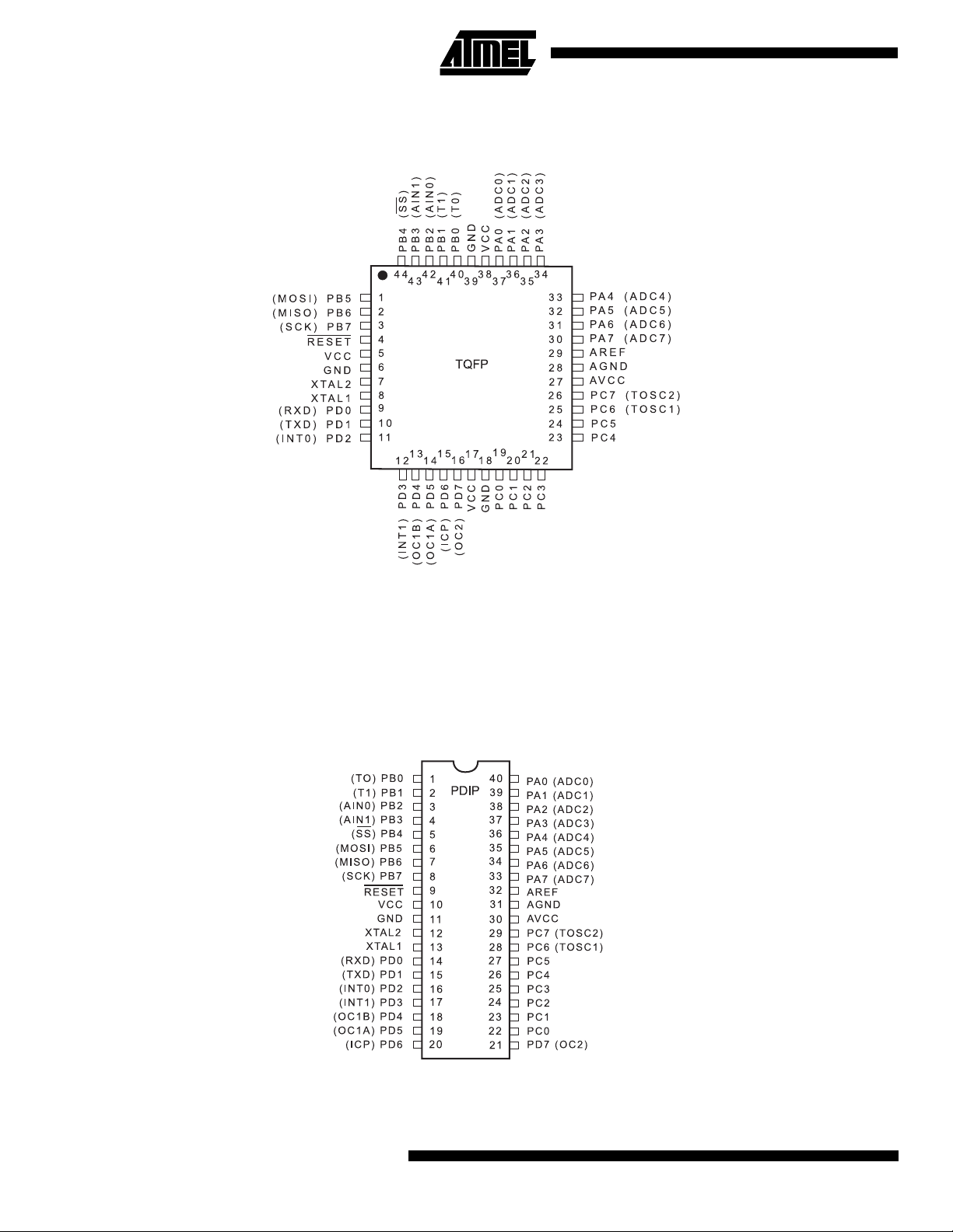
Pin Configurations
(SDA)
(SCL)
(SDA)
(SCL)
2
ATmega163(L)
Page 3
ATmega163(L)
Description
The ATmega163 is a low-power CMOS 8-bit microcontroller based on the AVR architecture. By executing powerful instructions in a single clock cycle, the ATmega163 achieves throughputs approaching 1 MIPS per MHz allowing the system
designer to optimize power consumption versus processing speed.
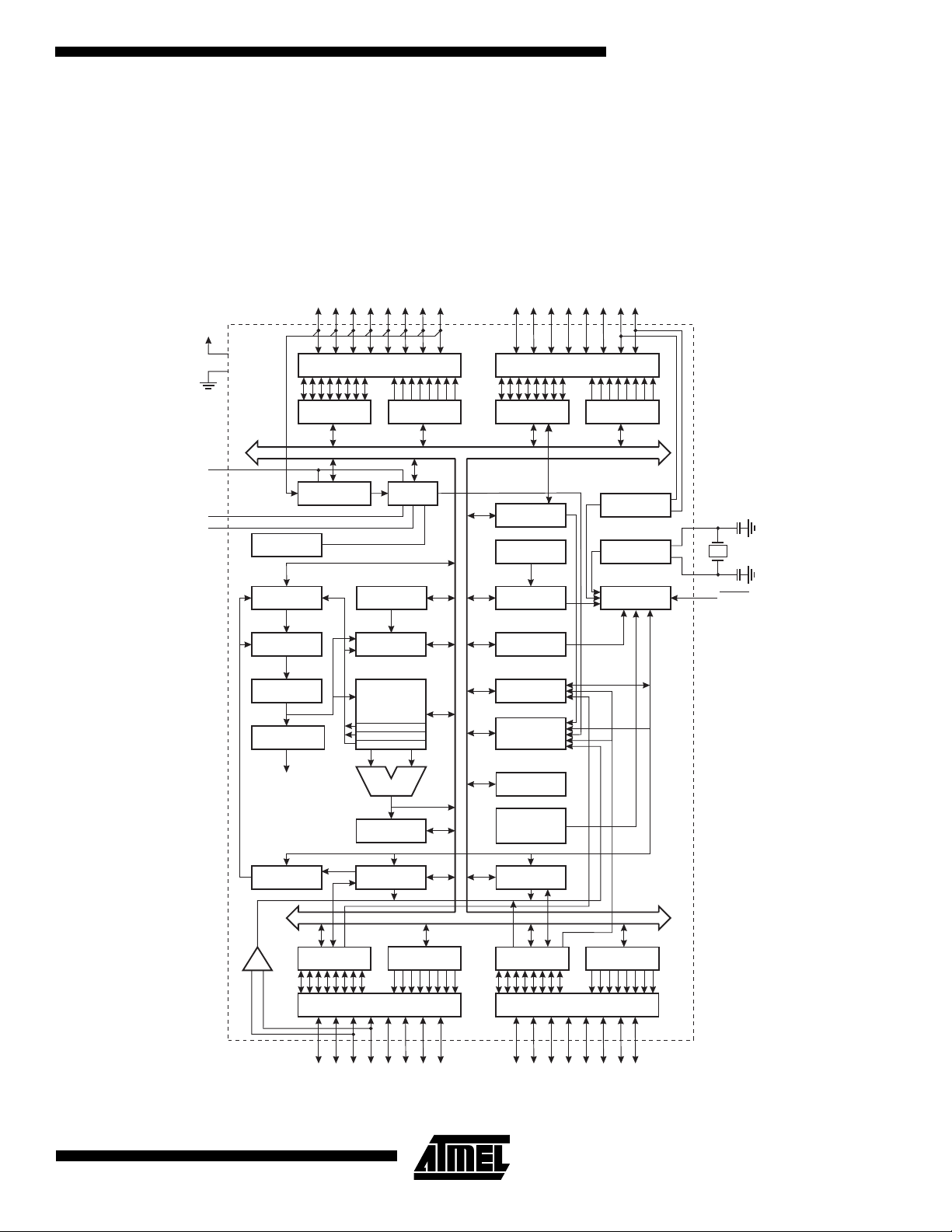
Block Diagram
Figure 1. Block Diagram
PA0 - PA7
VCC
PC0 - PC7
GND
AVCC
AGND
AREF
DATA REGISTER
INTERNAL
REFERENCE
PROGRAM
COUNTER
PROGRAM
FLASH
INSTRUCTION
REGISTER
INSTRUCTION
DECODER
CONTROL
LINES
PORTA DRIVERS
PORTA
ANALOG MUX
REG. PORTA
STACK
POINTER
SRAM
GENERAL
PURPOSE
REGISTERS
X
Y
Z
ALU
STATUS
REGISTER
DATA DIR.
ADC
8-BIT DATA BUS
PORTC DRIVERS
DATA REGISTER
PORTC
2-WIRE SERIAL
INTERFACE
INTERNAL
OSCILLATOR
WATCHDOG
TIMER
MCU CONTROL
REGISTER
TIMER/
COUNTERS
INTERRUPT
UNIT
EEPROM
INTERNAL
CALIBRATED
OSCILLATOR
DATA DIR.
REG. PORTC
OSCILLATOR
OSCILLATOR
TIMING AND
CONTROL
XTAL1
XTAL2
RESET
PROGRAMMING
LOGIC
DATA REGISTER
+
-
ANALOG
COMPARATOR
PORTB
PORTB DRIVERS
SPI
PB0 - PB7
DATA DIR.
REG. PORTB
UART
DATA REGISTER
PORTD
PORTD DRIVERS
PD0 - PD7
DATA DIR.
REG. PORTD
3
Page 4

The AVR core combines a rich instruction set with 32 general purpose working registers. All the 32 registers are directly
connected to the Arithmetic Logic Unit (ALU), allowing two independent registers to be accessed in one single instruction
executed in one clock cycle. The resulting architecture is more code efficient while achieving throughputs up to ten times
faster than conventional CISC microcontrollers.
The ATmega163 provides the following features: 16K bytes of In-System Self-Programmable Flash, 512 bytes EEPROM,
1024 bytes SRAM, 32 general purpose I/O lines, 32 general purpose working registers, three flexible timer/counters with
compare modes, internal and external interrupts, a byte oriented 2-wire Serial Interface, an 8-channel, 10-bit ADC, a programmable Watchdog Timer with internal oscillator, a programmable serial UART, an SPI serial port, and four software
selectable power saving modes. The Idle mode stops the CPU while allowing the SRAM, timer/counters, SPI port, and
interrupt system to continue functioning. The Power-down mode saves the register contents but freezes the oscillator, disabling all other chip functions until the next interrupt or hardware reset. In Power Save mode, the asynchronous timer
oscillator continues to run, allowing the user to maintain a timer base while the rest of the device is sleeping. The ADC
Noise Reduction Mode stops the CPU and all I/O modules except asynchronous timer and ADC, to minimize switching
noise during ADC conversions.
The on-chip ISP Flash can be programmed through an SPI serial interface or a conventional programmer. By installing a
self-programming boot loader, the microcontroller can be updated within the application without any external components.
The boot program can use any interface to download the application program in the Application Flash memory. By combining an 8-bit CPU with In-System self-programmable Flash on a monolithic chip, the Atmel ATmega163 is a powerful
microcontroller that provides a highly flexible and cost effective solution to many embedded control applications.
The ATmega163 AVR is supported with a full suite of program and system development tools including: C compilers,
macro assemblers, program debugger/simulators, in-circuit emulators, and evaluation kits.
Pin Descriptions
VCC
Digital supply voltage
GND
Digital ground
Port A (PA7..PA0)
Port A serves as the analog inputs to the A/D Converter.
Port A also serves as an 8-bit bi-directional I/O port, if the A/D Converter is not used. Port pins can provide internal pull-up
resistors (selected for each bit). The Port A output buffers can sink 20mA and can drive LED displays directly. When pins
PA0 to PA7 are used as inputs and are externally pulled low, they will source current if the internal pull-up resistors are activated. The Port A pins are tristated when a reset condition becomes active, even if the clock is not running.
Port B (PB7..PB0)
Port B is an 8-bit bi-directional I/O port with internal pull-up resistors (selected for each bit). The Port B output buffers can
sink 20 mA. As inputs, Port B pins that are externally pulled low will source current if the pull-up resistors are activated. Port
B also serves the functions of various special features of the ATmega83/163 as listed on page 100. The Port B pins are
tristated when a reset condition becomes active, even if the clock is not running.
Port C (PC7..PC0)
Port C is an 8-bit bi-directional I/O port with internal pull-up resistors (selected for each bit). The Port C output buffers can
sink 20 mA. As inputs, Port C pins that are externally pulled low will source current if the pull-up resistors are activated. The
Port C pins are tristated when a reset condition becomes active, even if the clock is not running.
Port C also serves the functions of various special features of the ATmega163 as listed on page 107.
4
ATmega163(L)
Page 5

ATmega163(L)
Port D (PD7..PD0)
Port D is an 8-bit bidirectional I/O port with internal pull-up resistors (selected for each bit). The Port D output buffers can
sink 20 mA. As inputs, Port D pins that are externally pulled low will source current if the pull-up resistors are activated. Port
D also serves the functions of various special features of the ATmega163 as listed on page 110. The Port D pins are
tristated when a reset condition becomes active, even if the clock is not running.
RESET
Reset input. A low level on this pin for more than 500 ns will generate a reset, even if the clock is not running. Shorter
pulses are not guaranteed to generate a reset.
XTAL1
Input to the inverting oscillator amplifier and input to the internal clock operating circuit.
XTAL2
Output from the inverting oscillator amplifier.
AVCC
This is the supply voltage pin for Port A and the A/D Converter. It should be externally connected to VCC, even if the ADC
is not used. If the ADC is used, it should be connected to VCC through a low-pass filter. See page 90 for details on operation of the ADC.
AREF
This is the analog reference input pin for the A/D Converter. For ADC operations, a voltage in the range 2.5V to AV
be applied to this pin.
AGND
Analog ground. If the board has a separate analog ground plane, this pin should be connected to this ground plane. Otherwise, connect to GND.
CC
can
Clock Options
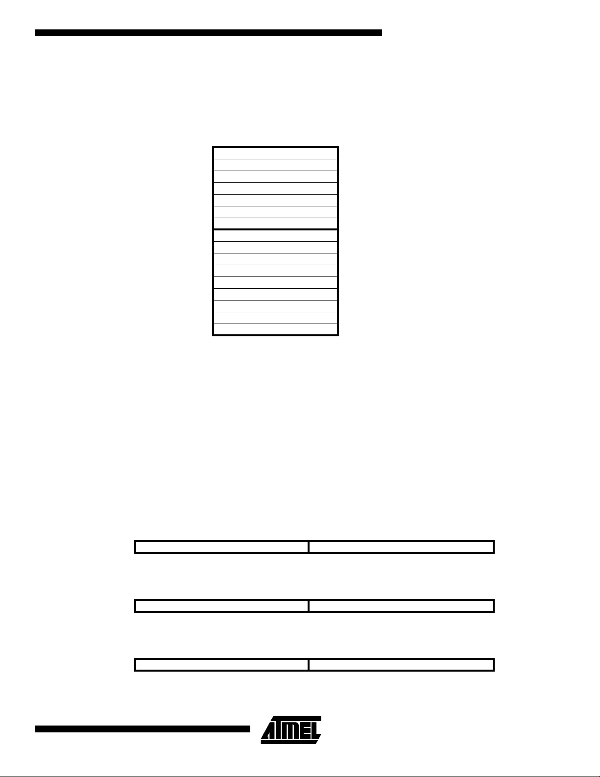
The device has the following clock source options, selectable by Flash fuse bits as shown:
Table 1. Device Clocking Options Select
Device Clocking Option CKSEL3..0
External Crystal/Ceramic Resonator 1111 - 1010
External Low-frequency Crystal 1001 - 1000
External RC Oscillator 0111 - 0101
Internal RC Oscillator 0100 - 0010
External Clock 0001 - 0000
Note: “1” means unprogrammed, “0” means programmed.
The various choices for each clocking option give different start-up times as shown in Table 5 on page 22.
Internal RC Oscillator
The internal RC oscillator option is an on-chip oscillator running at a fixed frequency of nominally 1 MHz. If selected, the
device can operate with no external components. The device is shipped with this option selected. See “EEPROM
Read/Write Access” on page 53 for information on calibrating this oscillator.
5
Page 6

Crystal Oscillator
XTAL1 and XTAL2 are input and output, respectively, of an inverting amplifier which can be configured for use as an onchip oscillator, as shown in Figure 2. Either a quartz crystal or a ceramic resonator may be used.
Figure 2. Oscillator Connections
External Clock
To drive the device from an external clock source, XTAL1 should be driven as shown in Figure 3.
Figure 3. External Clock Drive Configuration
External RC Oscillator
For timing insensitive applications, the external RC configuration shown in Figure 4 can be used. For details on how to
choose R and C, see Table 63 on page 140.
Figure 4. External RC Configuration
CC
V
R
C
NC
XTAL2
XTAL1
GND
Timer Oscillator
For the Timer Oscillator pins, PC6(TOSC1) and PC7(TOSC2), the crystal is connected directly between the pins. No external capacitors are needed. The oscillator is optimized for use with a 32,768 Hz watch crystal. Applying an external clock
source to the PC6 (TOSC1) pin is not recommended.
6
ATmega163(L)
Page 7
ATmega163(L)
Architectural Overview
The fast-access register file concept contains 32 x 8-bit general purpose working registers with a single clock cycle access
time. This means that during one single clock cycle, one Arithmetic Logic Unit (ALU) operation is executed. Two operands
are output from the register file, the operation is executed, and the result is stored back in the register file - in one clock
cycle.
Six of the 32 registers can be used as three 16-bits indirect address register pointers for Data Space addressing - enabling
efficient address calculations. One of the three address pointers is also used as the address pointer for look-up tables in
Flash program memory. These added function registers are the 16-bits X-register, Y-register, and Z-register.
The ALU supports arithmetic and logic operations between registers or between a constant and a register. Single register
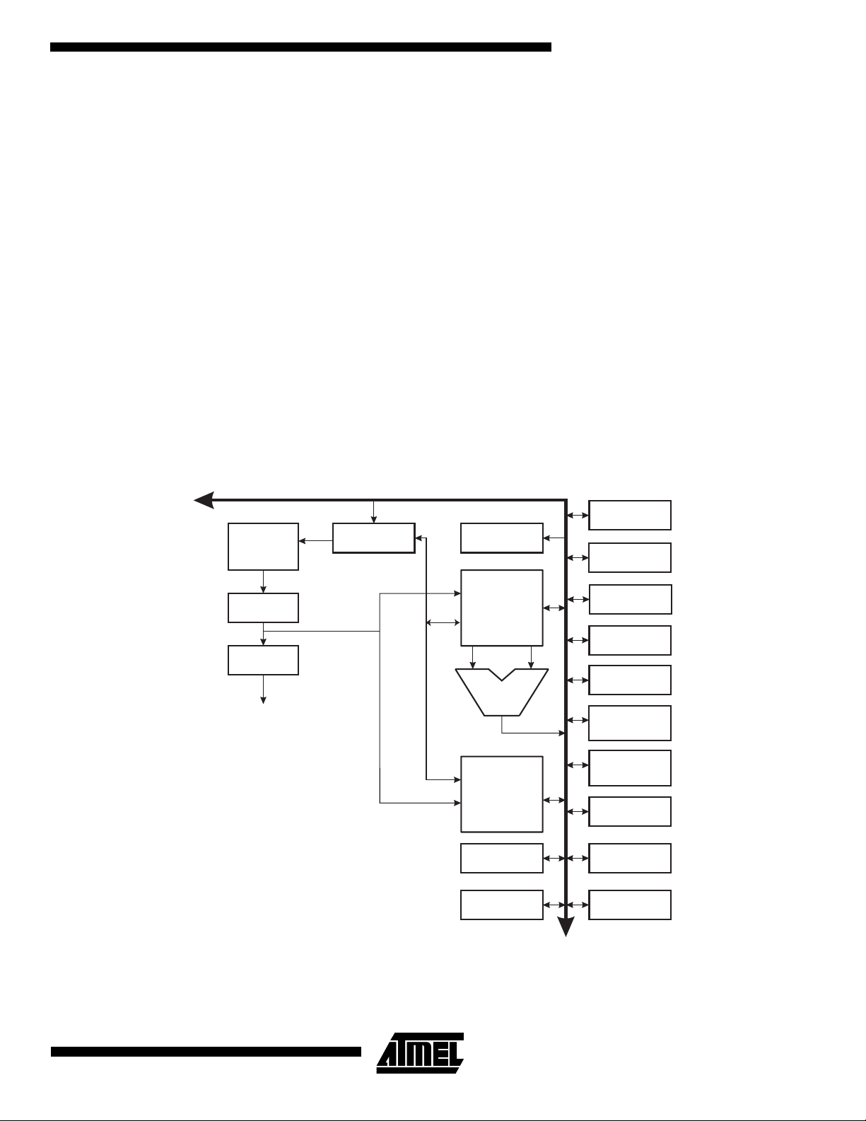
operations are also executed in the ALU. Figure 5 shows the ATmega163 AVR Enhanced RISC microcontroller
architecture.
In addition to the register operation, the conventional memory addressing modes can be used on the register file as well.
This is enabled by the fact that the register file is assigned the 32 lowest Data Space addresses ($00 - $1F), allowing them
to be accessed as though they were ordinary memory locations.
The I/O memory space contains 64 addresses for CPU peripheral functions as Control Registers, Timer/Counters, A/Dconverters, and other I/O functions. The I/O Memory can be accessed directly, or as the Data Space locations following
those of the register file, $20 - $5F.
Figure 5. The ATmega163 AVR RISC Architecture
8K X 16
Program
Memory
Instruction
Register
Instruction
Decoder
Control Lines
AVR ATmega163 Architecture
Data Bus 8-bit
Program
Counter
Direct Addressing
Indirect Addressing
Status
and Control
32 x 8
General
Purpose
Registrers
ALU
1024 x 8
Data
SRAM
512 x 8
EEPROM
Interrupt
Unit
SPI
Unit
Serial
UART
2-Wire Serial
Interface
8-bit
Timer/Counter
16-bit
Timer/Counter
with PWM
8-bit
Timer/Counter
with PWM
Watchdog
Timer
A/D Converter
32
I/O Lines
Analog
Comparator
7
Page 8

The AVR uses a Harvard architecture concept - with separate memories and buses for program and data. The program
memory is executed with a two stage pipeline. While one instruction is being executed, the next instruction is pre-fetched
from the program memory. This concept enables instructions to be executed in every clock cycle. The program memory is
in-system re-programmable Flash memory.
With the jump and call instructions, the whole 8K word address space is directly accessed. Most AVR instructions have a
single 16-bit word format. Every program memory address contains a 16- or 32-bit instruction.
Program Flash memory space is divided in two sections, the Boot Program section (256 to 2048 bytes, see page 115) and
the Application Program section. Both sections have dedicated Lock Bits for write and read/write protection. The SPM
instruction that writes into the Application Flash memory section is allowed only in the Boot program section.
During interrupts and subroutine calls, the return address program counter (PC) is stored on the stack. The stack is effectively allocated in the general data SRAM, and consequently the stack size is only limited by the total SRAM size and the
usage of the SRAM. All user programs must initialize the SP in the reset routine (before subroutines or interrupts are executed). The 11-bit stack pointer SP is read/write accessible in the I/O space.
The 1024 bytes data SRAM can be easily accessed through the five different addressing modes supported in the AVR
architecture.
The memory spaces in the AVR architecture are all linear and regular memory maps.
A flexible interrupt module has its control registers in the I/O space with an additional global interrupt enable bit in the status
register. All interrupts have a separate interrupt vector in the interrupt vector table at the beginning of the program memory.
The interrupts have priority in accordance with their interrupt vector position. The lower the interrupt vector address, the
higher the priority.
Figure 6. Memory Maps
Program Memory
Application Flash Section
Boot Flash Section
$0000
$1FFF
8
ATmega163(L)
Page 9
ATmega163(L)
The General Purpose Register File
Figure 7 shows the structure of the 32 general purpose working registers in the CPU.
Figure 7. AVR CPU General Purpose Working Registers
70Addr.
R0 $00
R1 $01
R2 $02
…
R13 $0D
General R14 $0E
Purpose R15 $0F
Working R16 $10
Registers R17 $11
…
R26 $1A X-register low byte
R27 $1B X-register high byte
R28 $1C Y-register low byte
R29 $1D Y-register high byte
R30 $1E Z-register low byte
R31 $1F Z-register high byte
All the register operating instructions in the instruction set have direct and single cycle access to all registers. The only
exception is the five constant arithmetic and logic instructions SBCI, SUBI, CPI, ANDI, and ORI between a constant and a
register, and the LDI instruction for load immediate constant data. These instructions apply to the second half of the registers in the register file - R16..R31. The general SBC, SUB, CP, AND, and OR and all other operations between two
registers or on a single register apply to the entire register file.
As shown in Figure 7, each register is also assigned a data memory address, mapping them directly into the first 32 locations of the user Data Space. Although not being physically implemented as SRAM locations, this memory organization
provides great flexibility in access of the registers, as the X, Y, and Z registers can be set to index any register in the file.
The X-register, Y-register, And Z-register
The registers R26..R31 have some added functions to their general purpose usage. These registers are address pointers
for indirect addressing of the Data Space. The three indirect address registers X, Y, and Z are defined as:
Figure 8. The X, Y, and Z Registers
15 XH XL 0
X - register 70 0 7 0
R27 ($1B) R26 ($1A)
15 YH YL 0
Y - register 70 0 7 0
R29 ($1D) R28 ($1C)
15 ZH ZL 0
Z - register 70 0 7 0
R30 ($1F) R31 ($1E)
9
Page 10
In the different addressing modes these address registers have functions as fixed displacement, automatic increment and
decrement (see the descriptions for the different instructions).
The ALU - Arithmetic Logic Unit
The high-performance AVR ALU operates in direct connection with all the 32 general purpose working registers. Within a
single clock cycle, ALU operations between registers in the register file are executed. The ALU operations are divided into
three main categories - arithmetic, logical, and bit-functions.
ATmega163 also provides a powerful multiplier supporting
both signed/unsigned multiplication and fractional format. See the Instruction Set section for a detailed description.
The In-System Self-programmable Flash Program Memory
The ATmega163 contains 16K bytes on-chip In-System Self-Programmable Flash memory for program storage. Since all
instructions are 16- or 32-bit words, the Flash is organized as 8K x 16. The Flash Program memory space is divided in two
sections, Boot Program section and Application Program section.
The Flash memory has an endurance of at least 1000 write/erase cycles. The ATmega163 Program Counter (PC) is 13 bits
wide, thus addressing the 8192 program memory locations. The operation of Boot Program section and associated Boot
Lock Bits for software protection are described in detail on page 115. See also page 132 for a detailed description on Flash
data serial downloading.
Constant tables can be allocated within the entire program memory address space (see the LPM - Load Program Memory
instruction description).
See also page 11 for the different program memory addressing modes.
The SRAM Data Memory
Figure 9 shows how the ATmega163 SRAM Memory is organized.
Figure 9. SRAM Organization
Register File
R0
R1
R2
...
R29
R30
R31
I/O Registers
$00
$01
$02
...
$3D
$3E
$3F
Data Address Space
$0000
$0001
$0002
...
$001D
$001E
$001F
$0020
$0021
$0022
...
$005D
$005E
$005F
Internal SRAM
$0060
$0061
...
$045E
$045F
10
ATmega163(L)
Page 11
ATmega163(L)
The lower 1120 Data Memory locations address the Register file, the I/O Memory, and the internal data SRAM. The first 96
locations address the Register File + I/O Memory, and the next 1024 locations address the internal data SRAM.
The five different addressing modes for the data memory cover: Direct, Indirect with Displacement, Indirect, Indirect with
Pre-Decrement, and Indirect with Post-Increment. In the register file, registers R26 to R31 feature the indirect addressing
pointer registers.
The direct addressing reaches the entire data space.
The Indirect with Displacement mode features a 63 address locations reach from the base address given by the Y or Z-
register.
When using register indirect addressing modes with automatic pre-decrement and post-increment, the address registers X,
Y, and Z are decremented and incremented.
The 32 general purpose working registers, 64 I/O registers, and the 1024 bytes of internal data SRAM in the ATmega163
are all accessible through all these addressing modes.
The Program and Data Addressing Modes
The ATmega163 AVR Enhanced RISC microcontroller supports powerful and efficient addressing modes for access to the
program memory (Flash) and data memory (SRAM, Register File, and I/O Memory). This section describes the different
addressing modes supported by the AVR architecture. In the figures, OP means the operation code part of the instruction
word. To simplify, not all figures show the exact location of the addressing bits.
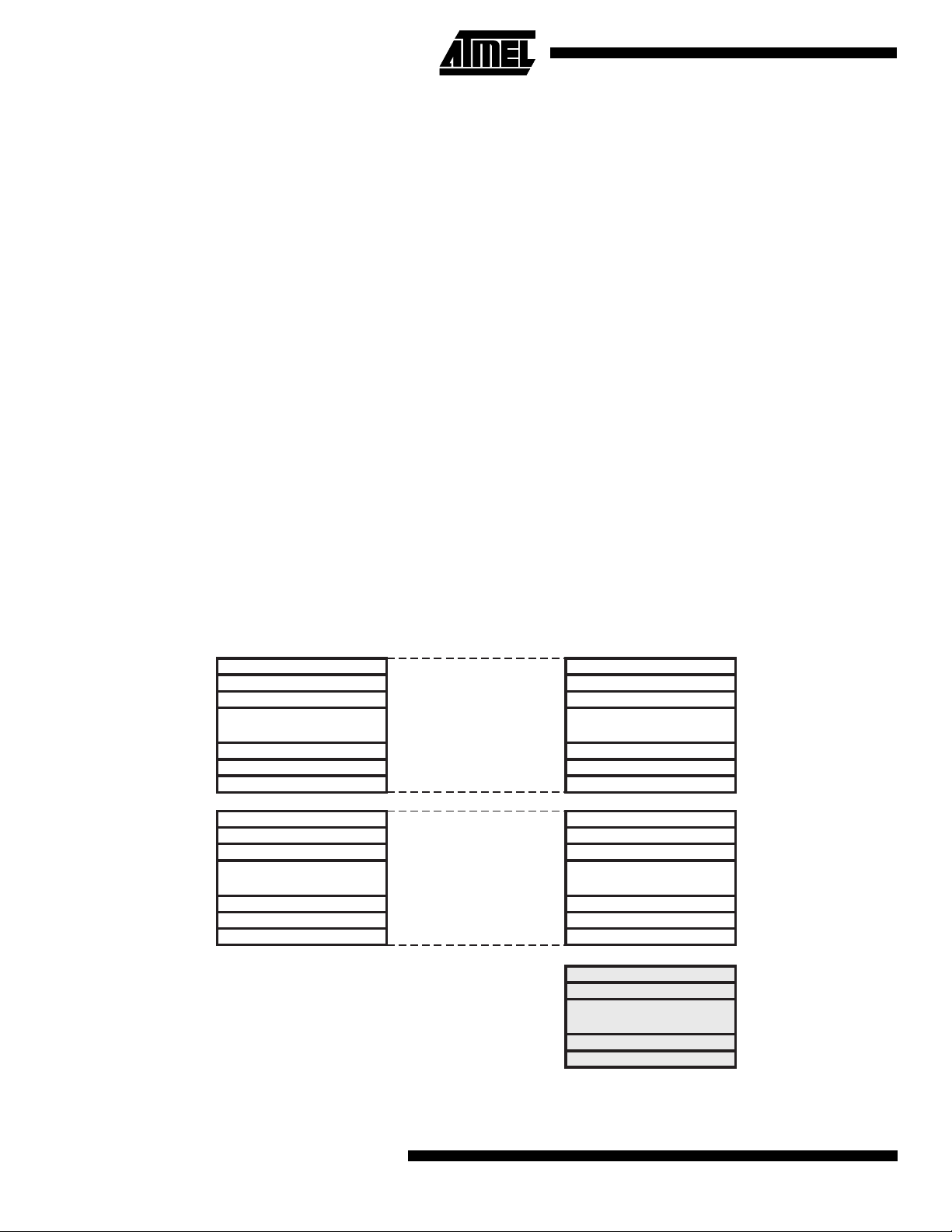
Register Direct, Single Register Rd
Figure 10. Direct Single Register Addressing
The operand is contained in register d (Rd).
Register Direct, Two Registers Rd And Rr
Figure 11. Direct Register Addressing, Two Registers
Operands are contained in register r (Rr) and d (Rd). The result is stored in register d (Rd).
11
Page 12
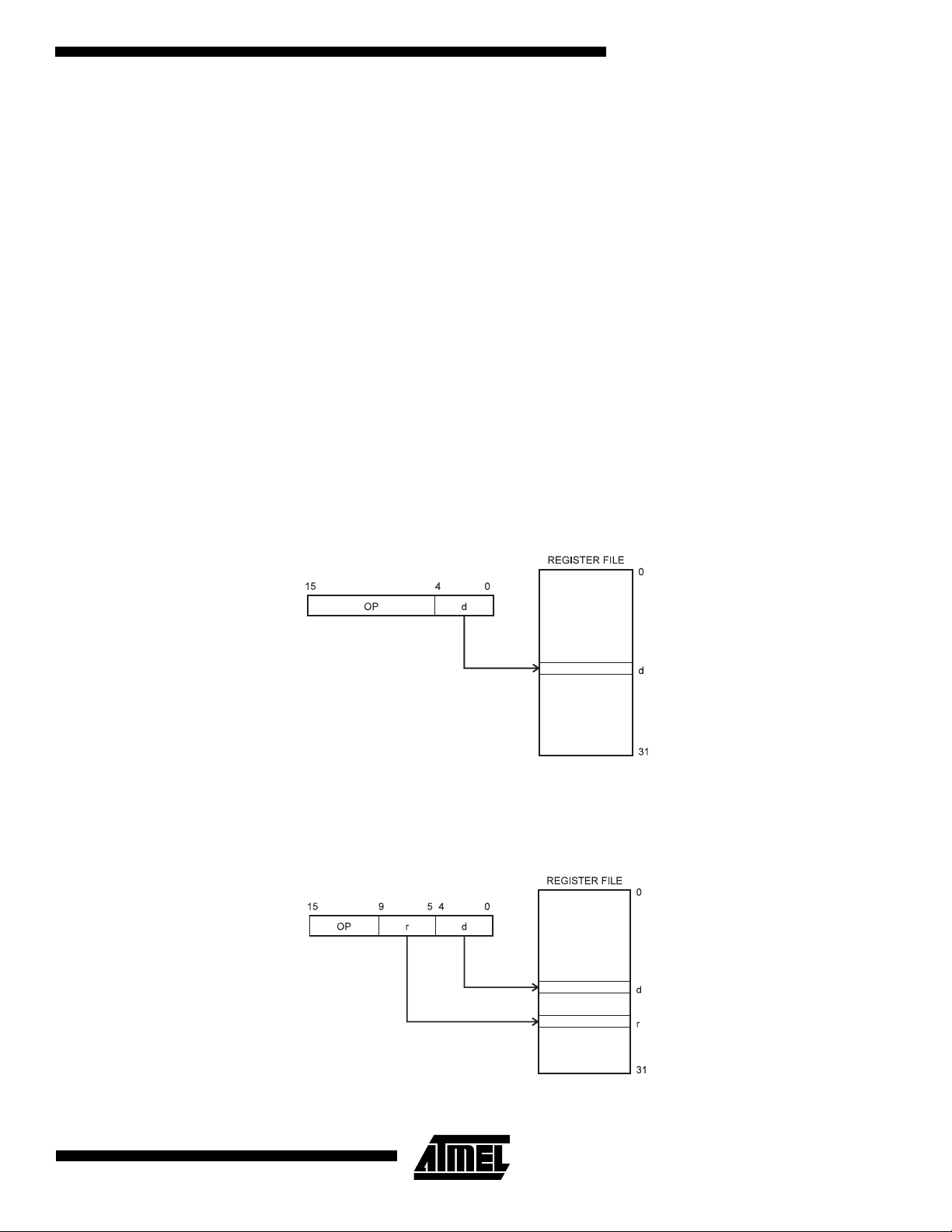
I/O Direct
Figure 12. I/O Direct Addressing
Operand address is contained in 6 bits of the instruction word. n is the destination or source register address.
Data Direct
Figure 13. Direct Data Addressing
16 LSBs
20 19
16
31
OP Rr/Rd
15 0
Data Space
$0000
$045F
A 16-bit Data Address is contained in the 16 LSBs of a two-word instruction. Rd/Rr specify the destination or source
register.
Data Indirect With Displacement
Figure 14. Data Indirect with Displacement
15
Y OR Z - REGISTER
15
OP an
Data Space
0
05610
$0000
$045F
Operand address is the result of the Y or Z-register contents added to the address contained in 6 bits of the instruction
word.
12
ATmega163(L)
Page 13
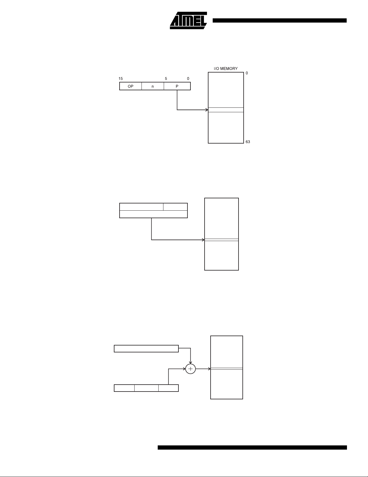
Data Indirect
Figure 15. Data Indirect Addressing
ATmega163(L)
015
X, Y OR Z - REGISTER
Operand address is the contents of the X, Y, or the Z-register.
Data Indirect With Pre-decrement
Figure 16. Data Indirect Addressing With Pre-decrement
015
X, Y OR Z - REGISTER
-1
Data Space
Data Space
$0000
$045F
$0000
$045F
The X, Y or the Z-register is decremented before the operation. Operand address is the decremented contents of the X, Y
or the Z-register.
Data Indirect With Post-increment
Figure 17. Data Indirect Addressing With Post-increment
Data Space
015
X, Y OR Z - REGISTER
1
$0000
$045F
The X, Y, or the Z-register is incremented after the operation. Operand address is the content of the X, Y, or the Z-register
prior to incrementing.
13
Page 14
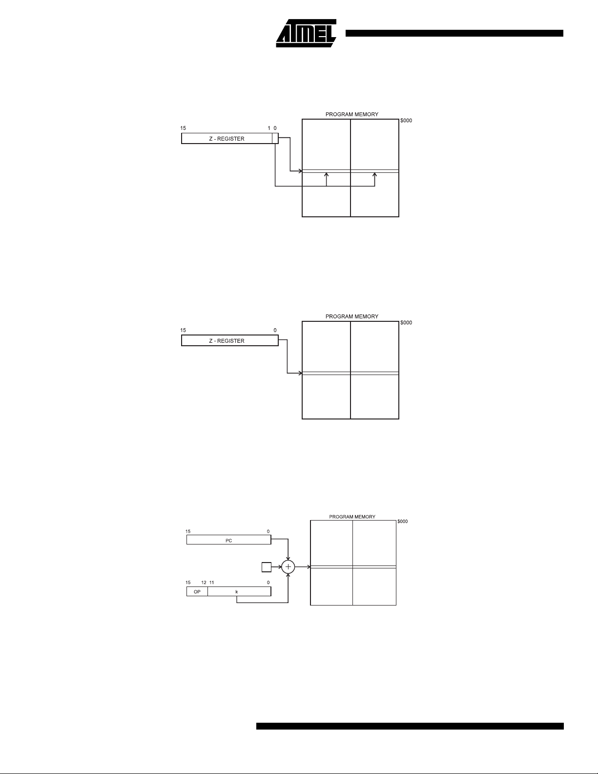
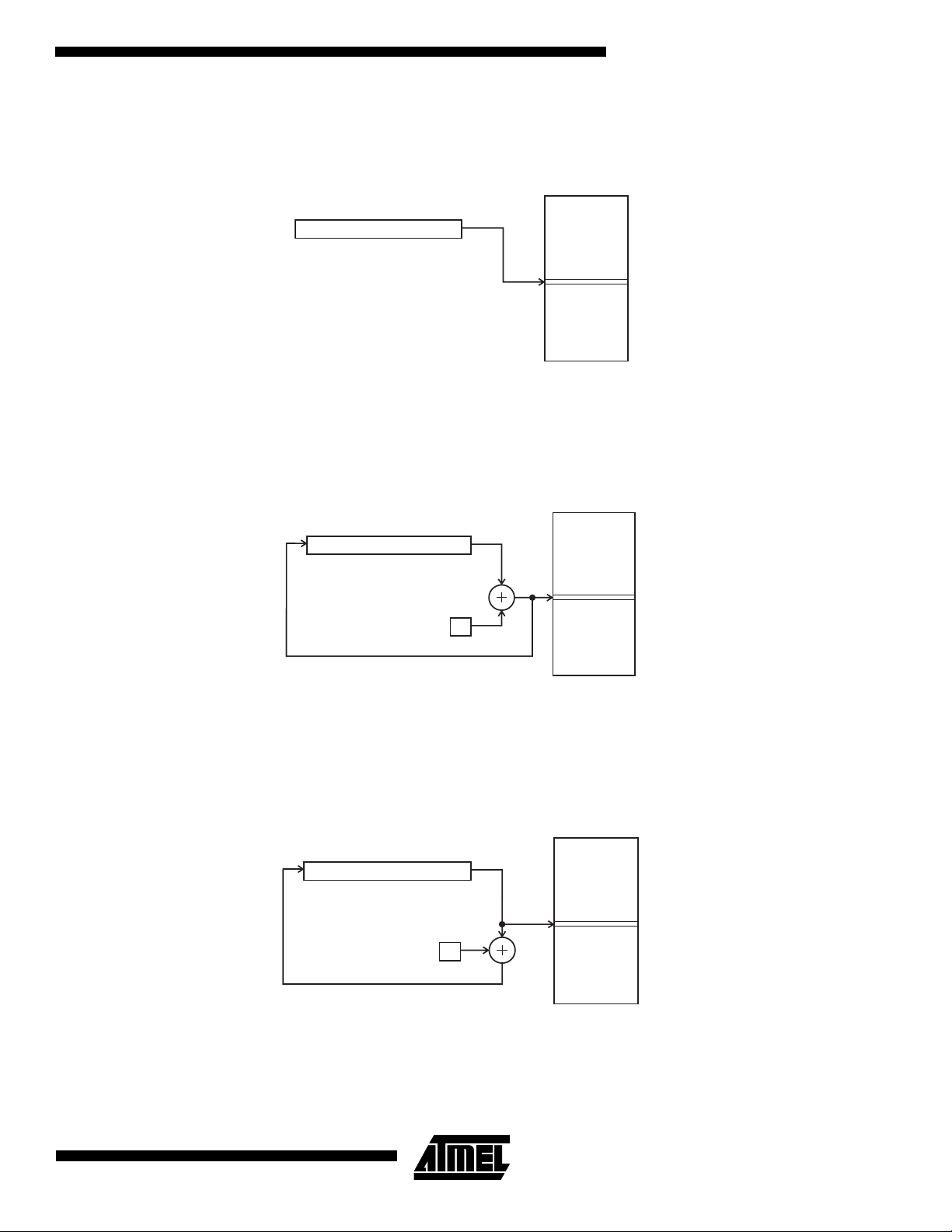
Constant Addressing Using The LPM and SPM Instructions
Figure 18. Code Memory Constant Addressing
$1FFF
Constant byte address is specified by the Z-register contents. The 15 MSBs select word address (0 - 8K). For LPM, the
LSB selects low byte if cleared (LSB = 0) or high byte if set (LSB = 1). For SPM, the LSB should be cleared.
Indirect Program Addressing, IJMP and ICALL
Figure 19. Indirect Program Memory Addressing
$1FFF
Program execution continues at address contained by the Z-register (i.e. the PC is loaded with the contents of the Zregister).
Relative Program Addressing, RJMP and RCALL
Figure 20. Relative Program Memory Addressing
1
$1FFF
Program execution continues at address PC + k + 1. The relative address k is from -2048 to 2047.
14
ATmega163(L)
Page 15
ATmega163(L)
The EEPROM Data Memory
The ATmega163 contains 512 bytes of data EEPROM memory. It is organized as a separate data space, in which single
bytes can be read and written. The EEPROM has an endurance of at least 100,000 write/erase cycles. The access
between the EEPROM and the CPU is described on page 53 specifying the EEPROM Address Registers, the EEPROM
Data Register, and the EEPROM Control Register.
For the SPI data downloading, see page 132 for a detailed description.
Memory Access Times and Instruction Execution Timing
This section describes the general access timing concepts for instruction execution and internal memory access.
The AVR CPU is driven by the System Clock Ø, directly generated from the main oscillator for the chip. No internal clock
division is used.
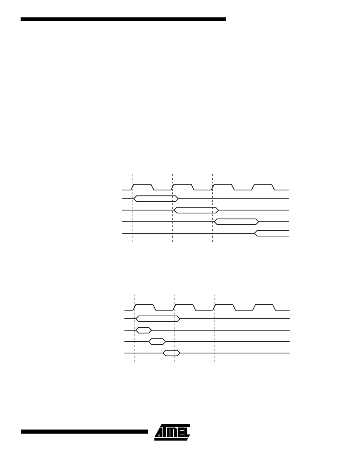
Figure 21 shows the parallel instruction fetches and instruction executions enabled by the Harvard architecture and the
fast-access register file concept. This is the basic pipelining concept to obtain up to 1 MIPS per MHz with the corresponding
unique results for functions per cost, functions per clocks, and functions per power-unit.
Figure 21. The Parallel Instruction Fetches and Instruction Executions
T1 T2 T3 T4
System Clock Ø
1st Instruction Fetch
1st Instruction Execute
2nd Instruction Fetch
2nd Instruction Execute
3rd Instruction Fetch
3rd Instruction Execute
4th Instruction Fetch
Figure 22 shows the internal timing concept for the register file. In a single clock cycle an ALU operation using two register
operands is executed, and the result is stored back to the destination register.
Figure 22. Single Cycle ALU Operation
T1 T2 T3 T4
System Clock Ø
Total Execution Time
Register Operands Fetch
ALU Operation Execute
Result Write Back
The internal data SRAM access is performed in two System Clock cycles as described in Figure 23.
15
Page 16
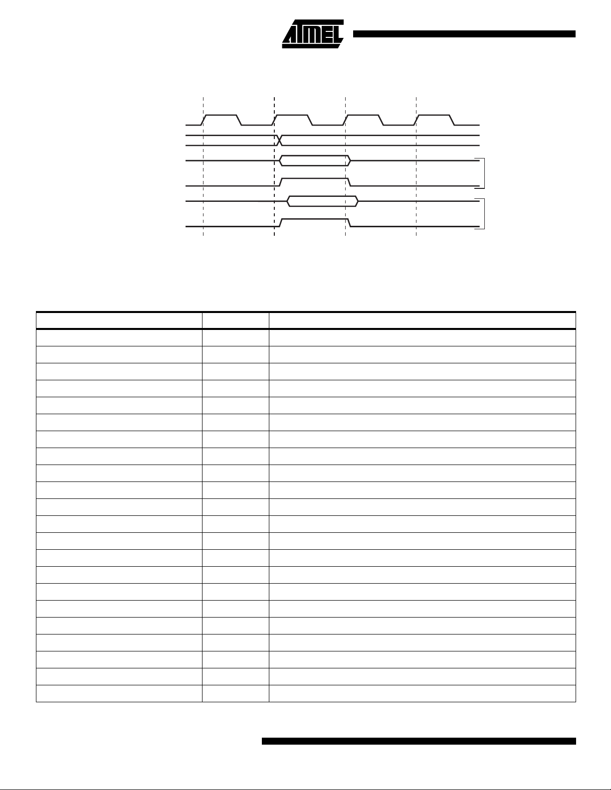
Figure 23. On-chip Data SRAM Access Cycles
T1 T2 T3 T4
System Clock Ø
Address
Data
WR
Data
RD
Prev. Address
Address
I/O Memory
The I/O space definition of the ATmega163 is shown in the following table:
Table 2. ATmega163 I/O Space
I/O Address (SRAM Address) Name Function
$3F ($5F) SREG Status REGister
$3E ($5E) SPH Stack Pointer High
$3D ($5D) SPL Stack Pointer Low
$3B ($5B) GIMSK General Interrupt MaSK Register
$3A ($5A) GIFR General Interrupt Flag Register
$39 ($59) TIMSK Timer/Counter Interrupt MaSK Register
Write
Read
$38 ($58) TIFR Timer/Counter Interrupt Flag Register
$37 ($57) SPMCR SPM Control Register
$36 ($56) TWCR 2-wire Serial Interface Control Register
$35 ($55) MCUCR MCU general Control Register
$34 ($54) MCUSR MCU general Status Register
$33 ($53) TCCR0 Timer/Counter0 Control Register
$32 ($52) TCNT0 Timer/Counter0 (8-bit)
$31 ($51) OSCCAL Oscillator Calibration Register
$30 ($50) SFIOR Special Function I/O Register
$2F ($4F) TCCR1A Timer/Counter1 Control Register A
$2E ($4E) TCCR1B Timer/Counter1 Control Register B
$2D ($4D) TCNT1H Timer/Counter1 High-byte
$2C ($4C) TCNT1L Timer/Counter1 Low-byte
$2B ($4B) OCR1AH Timer/Counter1 Output Compare Register A High-byte
$2A ($4A) OCR1AL Timer/Counter1 Output Compare Register A Low-byte
$29 ($49) OCR1BH Timer/Counter1 Output Compare Register B High-byte
16
ATmega163(L)
Page 17

Table 2. ATmega163 I/O Space (Continued)
I/O Address (SRAM Address) Name Function
$28 ($48) OCR1BL Timer/Counter1 Output Compare Register B Low-byte
$27 ($47) ICR1H T/C 1 Input Capture Register High-byte
$26 ($46) ICR1L T/C 1 Input Capture Register Low-byte
$25 ($45) TCCR2 Timer/Counter2 Control Register
$24 ($44) TCNT2 Timer/Counter2 (8-bit)
$23 ($43) OCR2 Timer/Counter2 Output Compare Register
$22 ($42) ASSR Asynchronous Mode Status Register
$21 ($41) WDTCR Watchdog Timer Control Register
$20 ($40) UBRRHI UART Baud Rate Register High-byte
$1F ($3F) EEARH EEPROM Address Register High-byte
$1E ($3E) EEARL EEPROM Address Register Low-byte
$1D ($3D) EEDR EEPROM Data Register
$1C ($3C) EECR EEPROM Control Register
$1B ($3B) PORTA Data Register, Port A
ATmega163(L)
$1A ($3A) DDRA Data Direction Register, Port A
$19 ($39) PINA Input Pins, Port A
$18 ($38) PORTB Data Register, Port B
$17 ($37) DDRB Data Direction Register, Port B
$16 ($36) PINB Input Pins, Port B
$15 ($35) PORTC Data Register, Port C
$14 ($34) DDRC Data Direction Register, Port C
$13 ($33) PINC Input Pins, Port C
$12 ($32) PORTD Data Register, Port D
$11 ($31) DDRD Data Direction Register, Port D
$10 ($30) PIND Input Pins, Port D
$0F ($2F) SPDR SPI I/O Data Register
$0E ($2E) SPSR SPI Status Register
$0D ($2D) SPCR SPI Control Register
$0C ($2C) UDR UART I/O Data Register
$0B ($2B) UCSRA UART Control and Status Register A
$0A ($2A) UCSRB UART Control and Status Register B
$09 ($29) UBRR UART Baud Rate Register
$08 ($28) ACSR Analog Comparator Control and Status Register
$07 ($27) ADMUX ADC Multiplexer Select Register
$06 ($26) ADCSR ADC Control and Status Register
$05 ($25) ADCH ADC Data Register High
17
Page 18
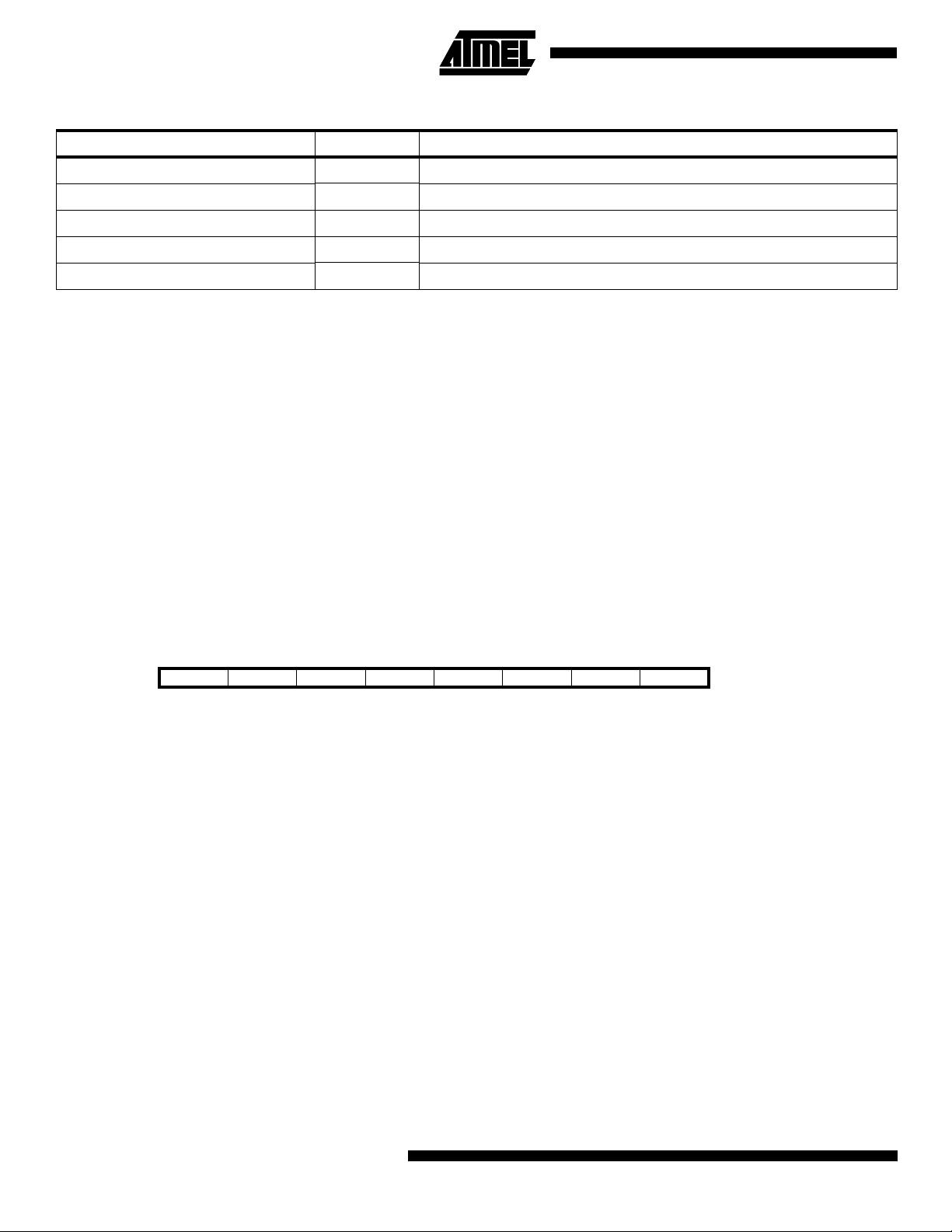
Table 2. ATmega163 I/O Space (Continued)
I/O Address (SRAM Address) Name Function
$04 ($24) ADCL ADC Data Register Low
$03 ($23) TWDR 2-wire Serial Interface Data Register
$02 ($22) TWAR 2-wire Serial Interface (Slave) Address Register
$01 ($21) TWSR 2-wire Serial Interface Status Register
$00 ($20) TWBR 2-wire Serial Interface Bit Rate Register
Note: Reserved and unused locations are not shown in the table.
All ATmega163 I/Os and peripherals are placed in the I/O space. The I/O locations are accessed by the IN and OUT
instructions, transferring data between the 32 general purpose working registers and the I/O space. I/O registers within the
address range $00 - $1F are directly bit-accessible using the SBI and CBI instructions. In these registers, the value of single bits can be checked by using the SBIS and SBIC instructions. Refer to the instruction set chapter for more details.
When using the I/O specific commands IN and OUT, the I/O addresses $00 - $3F must be used. When addressing I/O registers as SRAM, $20 must be added to these addresses. All I/O register addresses throughout this document are shown
with the SRAM address in parentheses.
For compatibility with future devices, reserved bits should be written to zero if accessed. Reserved I/O memory addresses
should never be written.
Some of the status flags are cleared by writing a logical one to them. Note that the CBI and SBI instructions will operate on
all bits in the I/O register, writing a one back into any flag read as set, thus clearing the flag. The CBI and SBI instructions
work with registers $00 to $1F only.
The I/O and peripherals control registers are explained in the following sections.
The Status Register - SREG
The AVR status register - SREG - at I/O space location $3F ($5F) is defined as:
Bit 76543210
$3F ($5F) I T H S V N Z C SREG
Read/Write R/W R/W R/W R/W R/W R/W R/W R/W
Initial value 0 0 0 0 0 0 0 0
Bit 7 - I: Global Interrupt Enable
•
The global interrupt enable bit must be set (one) for the interrupts to be enabled. The individual interrupt enable control is
then performed in the interrupt mask registers. If the global interrupt enable register is cleared (zero), none of the interrupts
are enabled independent of the values of the interrupt mask registers. The I-bit is cleared by hardware after an interrupt has
occurred, and is set by the RETI instruction to enable subsequent interrupts.
Bit 6 - T: Bit Copy Storage
•
The bit copy instructions BLD (Bit LoaD) and BST (Bit STore) use the T bit as source and destination for the operated bit. A
bit from a register in the register file can be copied into T by the BST instruction, and a bit in T can be copied into a bit in a
register in the register file by the BLD instruction.
Bit 5 - H: Half Carry Flag
•
The half carry flag H indicates a half carry in some arithmetic operations. See the Instruction Set Description for detailed
information.
Bit 4 - S: Sign Bit, S = N=⊕ V
•
The S-bit is always an exclusive or between the negative flag N and the two’s complement overflow flag V. See the Instruction Set Description for detailed information.
•
Bit 3 - V: Two’s Complement Overflow Flag
The two’s complement overflow flag V supports two’s complement arithmetics. See the Instruction Set Description for
detailed information.
18
ATmega163(L)
Page 19

ATmega163(L)
Bit 2 - N: Negative Flag
•
The negative flag N indicates a negative result in an arithmetic or logic operation. See the Instruction Set Description for
detailed information.
•
Bit 1 - Z: Zero Flag
The zero flag Z indicates a zero result in an arithmetic or logic operation. See the Instruction Set Description for detailed
information.
Bit 0 - C: Carry Flag
•
The carry flag C indicates a carry in an arithmetic or logic operation. See the Instruction Set Description for detailed
information.
Note that the status register is not automatically stored when entering an interrupt routine and restored when returning from
an interrupt routine. This must be handled by software.
The Stack Pointer - SP
The ATmega163 Stack Pointer is implemented as two 8-bit registers in the I/O space locations $3E ($5E) and $3D ($5D).
As the ATmega163 data memory has $460 locations, 11 bits are used.
Bit 151413121110 9 8
$3E ($5E) - - - - - SP10 SP9 SP8 SPH
$3D ($5D) SP7 SP6 SP5 SP4 SP3 SP2 SP1 SP0 SPL
76543210
Read/Write R R R R R R/W R/W R/W
R/W R/W R/W R/W R/W R/W R/W R/W
Initial value 00000000
00000000
The Stack Pointer points to the data SRAM stack area where the Subroutine and Interrupt Stacks are located. This Stack
space in the data SRAM must be defined by the program before any subroutine calls are executed or interrupts are
enabled. The Stack Pointer must be set to point above $60. The Stack Pointer is decremented by one when data is pushed
onto the Stack with the PUSH instruction, and it is decremented by two when the return address is pushed onto the Stack
with subroutine call and interrupt. The Stack Pointer is incremented by one when data is popped from the Stack with the
POP instruction, and it is incremented by two when data is popped from the Stack with return from subroutine RET or
return from interrupt RETI.
Reset and Interrupt Handling
The ATmega163 provides 17 different interrupt sources. These interrupts and the separate reset vector, each have a separate program vector in the program memory space. All interrupts are assigned individual enable bits which must be set
(one) together with the I-bit in the status register in order to enable the interrupt.
The lowest addresses in the program memory space are automatically defined as the Reset and Interrupt vectors. The
complete list of vectors is shown in Table 3. The list also determines the priority levels of the different interrupts. The lower
the address the higher is the priority level. RESET has the highest priority, and next is INT0 - the External Interrupt Request
0, etc.
19
Page 20

Table 3. Reset and Interrupt Vectors
Vector No. Program Source Interrupt Definition
Address
1$000
2 $002 INT0 External Interrupt Request 0
3 $004 INT1 External Interrupt Request 1
4 $006 TIMER2 COMP Timer/Counter2 Compare Match
5 $008 TIMER2 OVF Timer/Counter2 Overflow
6 $00A TIMER1 CAPT Timer/Counter1 Capture Event
7 $00C TIMER1 COMPA Timer/Counter1 Compare Match A
8 $00E TIMER1 COMPB Timer/Counter1 Compare Match B
9 $010 TIMER1 OVF Timer/Counter1 Overflow
10 $012 TIMER0 OVF Timer/Counter0 Overflow
11 $014 SPI, STC Serial Transfer Complete
12 $016 UART, RXC UART, Rx Complete
13 $018 UART, UDRE UART Data Register Empty
14 $01A UART, TXC UART, Tx Complete
15 $01C ADC ADC Conversion Complete
(1)
RESET External Pin, Power-on Reset, Brown-out Reset and Watchdog Reset
16 $01E EE_RDY EEPROM Ready
17 $020 ANA_COMP Analog Comparator
18 $022 TWSI 2-wire Serial Interface
Note: 1. When the BOOTRST fuse is programmed, the device will jump to the Boot Loader address at reset, see “Boot Loader Sup-
port” on page 115.
The most typical and general program setup for the Reset and Interrupt Vector Addresses in ATmega163 is:
Address Labels Code Comments
$000 jmp RESET ; Reset Handler
$002 jmp EXT_INT0 ; IRQ0 Handler
$004 jmp EXT_INT1 ; IRQ1 Handler
$006 jmp TIM2_COMP ; Timer2 Compare Handler
$008 jmp TIM2_OVF ; Timer2 Overflow Handler
$00a jmp TIM1_CAPT ; Timer1 Capture Handler
$00c jmp TIM1_COMPA ; Timer1 CompareA Handler
$00e jmp TIM1_COMPB ; Timer1 CompareB Handler
$010 jmp TIM1_OVF ; Timer1 Overflow Handler
$012 jmp TIM0_OVF ; Timer0 Overflow Handler
$014 jmp SPI_STC ; SPI Transfer Complete Handler
$016 jmp UART_RXC ; UART RX Complete Handler
$018 jmp UART_DRE ; UDR Empty Handler
$01a jmp UART_TXC ; UART TX Complete Handler
$01c jmp ADC ; ADC Conversion Complete Interrupt Handler
$01e jmp EE_RDY ; EEPROM Ready Handler
$020 jmp ANA_COMP ; Analog Comparator Handler
$022 jmp TWSI ; 2-wire Serial Interface Interrupt Handler
20
ATmega163(L)
Page 21

ATmega163(L)
;
$024 MAIN: ldi r16,high(RAMEND); Main program start
$025 out SPH,r16 ; Set stack pointer to top of RAM
$026 ldi r16,low(RAMEND)
$027 out SPL,r16
... ... ...
When the BOOTRST fuse is programmed and the boot section size set to 512 bytes, the most typical and general program
setup for the Reset and Interrupt Vector Addresses in ATmega163 is:
Address Labels Code Comments
$002 jmp EXT_INT0 ; IRQ0 Handler
... ... ...
$022 jmp TWSI ; 2-wire Serial Interface Interrupt Handler
;
$024 MAIN: ldi r16,high(RAMEND); Main program start
$025 out SPH,r16 ; Set stack pointer to top of RAM
$026 ldi r16,low(RAMEND)
$027 out SPL,r16
$028 <instr> xxx
;
.org $1f00
$1f00 jmp RESET ; Reset Handler
Reset Sources
The ATmega163 has four sources of reset:
• Power-on Reset. The MCU is reset when the supply voltage is below the power-on reset threshold (V
POT
).
• External Reset. The MCU is reset when a low level is present on the RESET pin for more than 500 ns.
• Watchdog Reset. The MCU is reset when the Watchdog timer period expires and the Watchdog is enabled.
• Brown-out Reset. The MCU is reset when the supply voltage V
is below the brown-out reset threshold (V
CC
BOT
).
During reset, all I/O registers are set to their initial values, and the program starts execution from address $000 (unless the
BOOTRST fuse is programmed, as explained above). The instruction placed in this address location must be a JMP absolute jump - instruction to the reset handling routine. If the program never enables an interrupt source, the interrupt vectors are not used, and regular program code can be placed at these locations. The circuit diagram in Figure 24 shows the
reset logic. Table 4 and Table 5 define the timing and electrical parameters of the reset circuitry.
21
Page 22
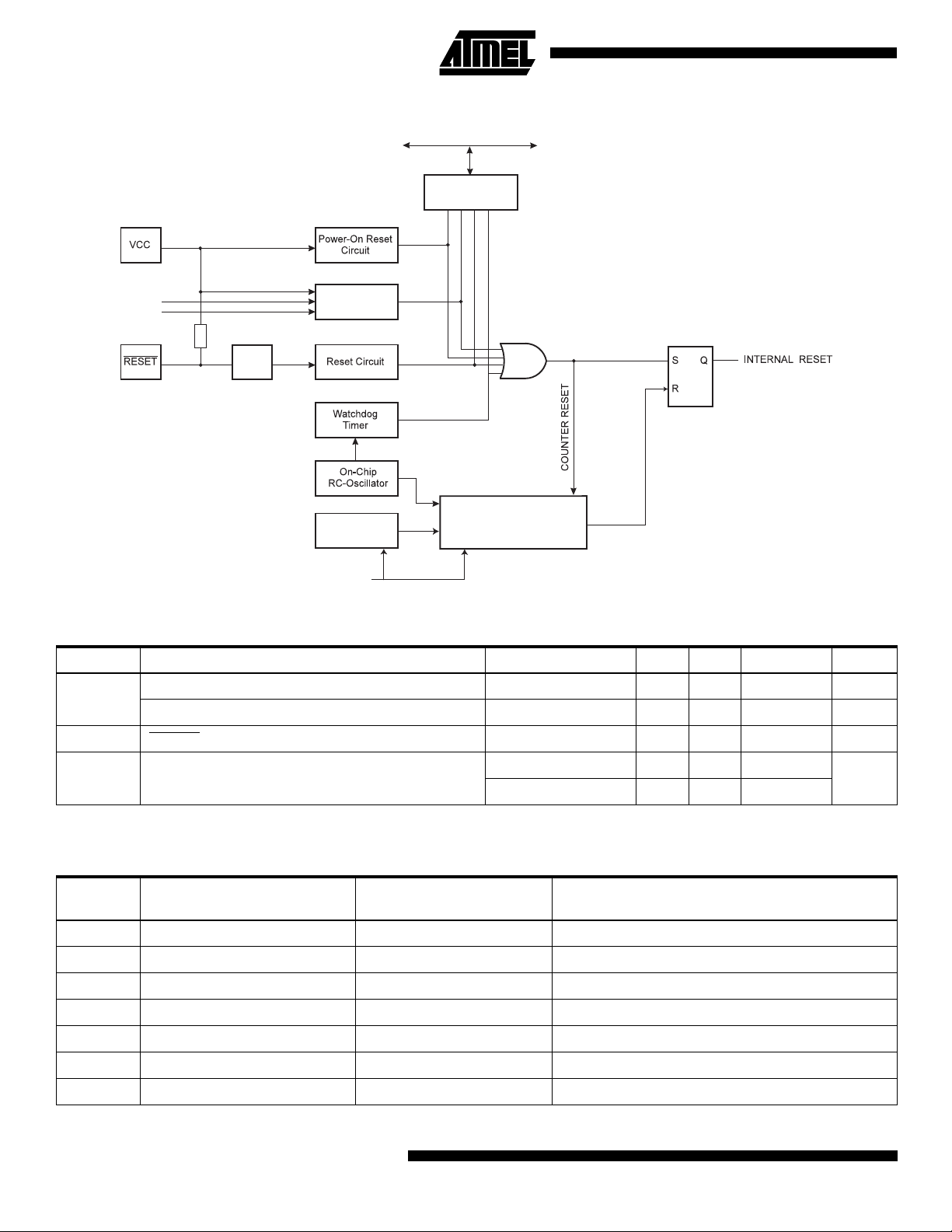
Figure 24. Reset Logic
DATA BU S
MCU Status
Register (MCUSR)
BORF
PORF
WDRF
EXTRF
BODEN
BODLEVEL
100-500kΩ
SPIKE
FILTER
Table 4. Reset Characteristics (VCC = 5.0V)
Brown-Out
Reset Circuit
Clock
Generator
CKSEL[3:0]
(1)
CK
Delay Counters
TIMEOUT
Symbol Parameter Condition Min Typ Max Units
V
POT
V
RST
Power-on Reset Threshold Voltage (rising) 1.0 1.4 1.8 V
Power-on Reset Threshold Voltage (falling)
RESET Pin Threshold Voltage - - 0.85 V
(2)
0.4 0.6 0.8 V
CC
Brown-out Reset Threshold Voltage (BODLEVEL = 1) 2.5 2.7 2.9
V
BOT
(BODLEVEL = 0) 3.6 4.0 4.4
Notes: 1. Values are guidelines only. Actual values are TBD.
2. The Power-on Reset will not work unless the supply voltage has been below V
Table 5. Reset Delay Selections
(1)
POT
(falling).
V
V
CKSEL
(2)
Start-up Time, VCC = 2.7V,
BODLEVEL Unprogrammed
Start-up Time, VCC = 4.0V,
BODLEVEL Programmed Recommended Usage
(3)
0000 4.2 ms + 6 CK 5.8 ms + 6 CK Ext. Clock, fast rising power
0001 30 µs + 6 CK
(6)
0010
67 ms + 6 CK 92 ms + 6 CK Int. RC Oscillator, slowly rising power
(4)
10 µs + 6 CK
(5)
Ext. Clock, BOD enabled
0011 4.2 ms + 6 CK 5.8 ms + 6 CK Int. RC Oscillator, fast rising power
0100 30 µs + 6 CK
(4)
10 µs + 6 CK
(5)
Int. RC Oscillator, BOD enabled
0101 67 ms + 6 CK 92 ms + 6 CK Ext. RC Oscillator, slowly rising power
0110 4.2 ms + 6 CK 5.8 ms + 6 CK Ext. RC Oscillator, fast rising power
22
ATmega163(L)
Page 23
ATmega163(L)
Table 5. Reset Delay Selections
CKSEL
(2)
0111 30 µs + 6 CK
Start-up Time, VCC = 2.7V,
BODLEVEL Unprogrammed
(1)
(Continued)
(4)
Start-up Time, VCC = 4.0V,
BODLEVEL Programmed Recommended Usage
10 µs + 6 CK
(5)
Ext. RC Oscillator, BOD enabled
(3)
1000 67ms + 32K CK 92 ms + 32K CK Ext. Low-frequency Crystal
1001 67 ms + 1K CK 92 ms + 1K CK Ext. Low-frequency Crystal
1010 67 ms + 16K CK 92 ms + 16K CK Crystal Oscillator, slowly rising power
1011 4.2 ms + 16K CK 5.8 ms + 16K CK Crystal Oscillator, fast rising power
1100 30 µs + 16K CK
(4)
10 µs + 16K CK
(5)
Crystal Oscillator, BOD enabled
1101 67 ms + 1K CK 92 ms + 1K CK Ceramic Resonator/Ext. Clock, slowly rising power
1110 4.2 ms + 1K CK 5.8 ms + 1K CK Ceramic Resonator, fast rising power
1111 30 µs + 1K CK
(4)
10 µs + 1K CK
(5)
Ceramic Resonator, BOD enabled
Notes: 1. On power-up, the start-up time is increased with typ. 0.6 ms.
2. ‘1’ means unprogrammed, ‘0’ means programmed.
3. For possible clock selections, see “Clock Options” on page 5.
4. When BODEN is programmed, add 100 µs.
5. When BODEN is programmed, add 25 µs.
6. Default value.
Table 5 shows the start-up times from reset. When the CPU wakes up from power down or power save, only the clock
counting part of the start-up time is used. The watchdog oscillator is used for timing the real-time part of the start-up time.
The number of WDT oscillator cycles used for each time-out is shown in Table 6.
The frequency of the watchdog oscillator is voltage dependent as shown in the Electrical Characteristics section. The
device is shipped with CKSEL = ‘0010’ (Int. RC Oscillator, slowly rising power).
Table 6. Number of Watchdog Oscillator Cycles
BODLEVEL Vcc condition Time-out Number of cycles
Unprogrammed 2.7V 30 µs 8
Unprogrammed 2.7V 130 µs 32
Unprogrammed 2.7V 4.2 ms 1K
Unprogrammed 2.7V 67 ms 16K
Programmed 4.0V 10 µs 8
Programmed 4.0V 35 µs 32
Programmed 4.0V 5.8 ms 4K
Programmed 4.0V 92 ms 64K
Note: The bod-level fuse can be used to select start-up times even if the Brown-out detection is disabled (BODEN fuse
unprogrammed).
Power-on Reset
A Power-on Reset (POR) pulse is generated by an on-chip detection circuit. The detection level is defined in Table 4. The
POR is activated whenever V
is below the detection level. The POR circuit can be used to trigger the start-up reset, as
CC
well as to detect a failure in supply voltage.
A Power-on Reset (POR) circuit ensures that the device is reset from power-on. Reaching the power-on reset threshold
voltage invokes a delay counter, which determines the delay, for which the device is kept in RESET after V
rise. The
CC
time-out period of the delay counter can be defined by the user through the CKSEL fuses. The different selections for the
delay period are presented in Table 5. The RESET signal is activated again, without any delay, when the V
decreases
CC
below detection level.
23
Page 24
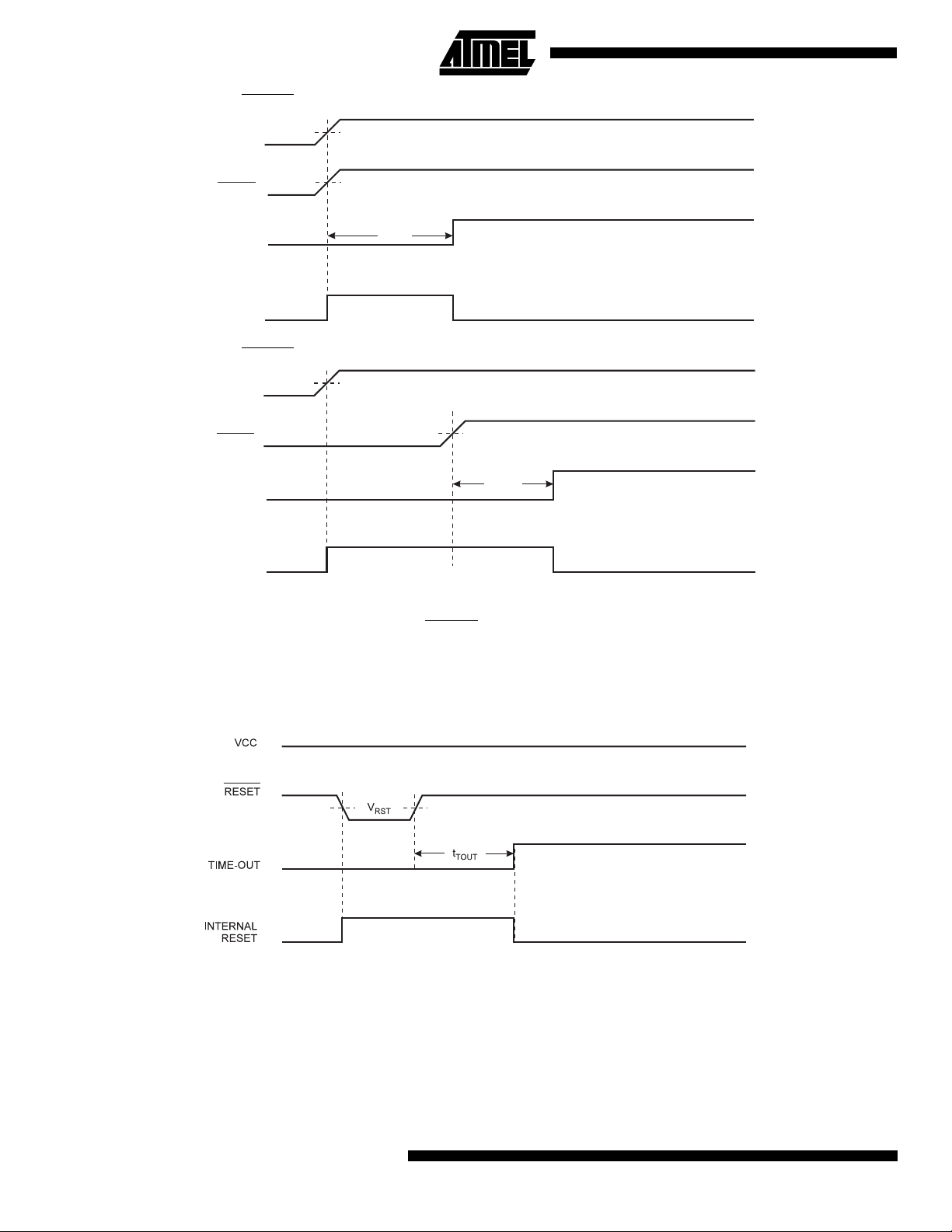
Figure 25. MCU Start-up, RESET
VCC
RESET
TIME-OUT
INTERNAL
RESET
Tied to VCC.
V
POT
V
RST
t
TOUT
Figure 26. MCU Start-up, RESET
VCC
RESET
TIME-OUT
INTERNAL
RESET
Extended Externally
V
POT
V
RST
t
TOUT
External Reset
An external reset is generated by a low level on the RESET
pin. Reset pulses longer than 500 ns will generate a reset,
even if the clock is not running. Shorter pulses are not guaranteed to generate a reset. When the applied signal reaches the
Reset Threshold Voltage - V
on its positive edge, the delay timer starts the MCU after the Time-out period t
RST
TOUT
has
expired.
Figure 27. External Reset During Operation
24
ATmega163(L)
Page 25
ATmega163(L)
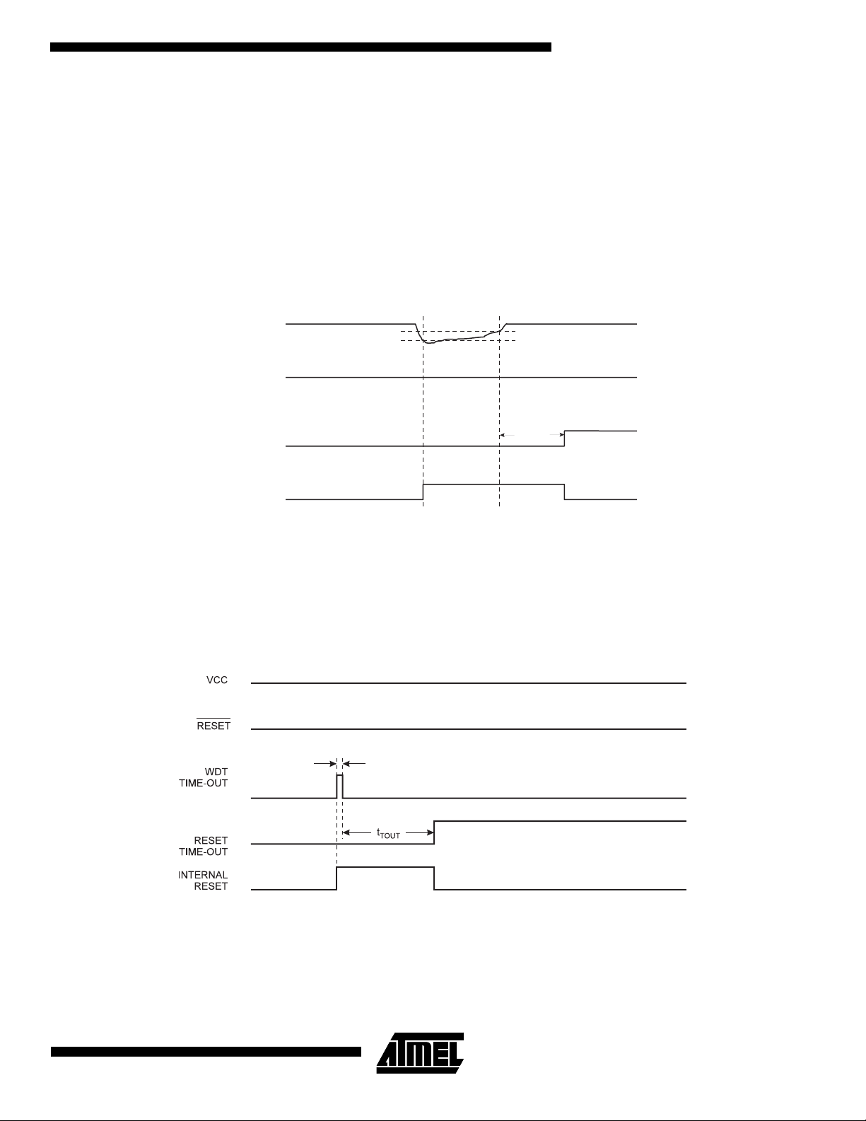
Brown-out Detection
ATmega163 has an on-chip brown-out detection (BOD) circuit for monitoring the V
circuit can be enabled/disabled by the fuse BODEN. When the BOD is enabled (BODEN programmed), and V
to a value below the trigger level, the brown-out reset is immediately activated. When V
the brown-out reset is deactivated after a delay. The delay is defined by the user in the same way as the delay of POR signal, in Table 5. The trigger level for the BOD can be selected by the fuse BODLEVEL to be 2.7V (BODLEVEL
unprogrammed), or 4.0V (BODLEVEL programmed). The trigger level has a hysteresis of 50 mV to ensure spike free
brown-out detection.
The BOD circuit will only detect a drop in V
if the voltage stays below the trigger level for longer than 9 µs for trigger level
CC
4.0V, 21 µs for trigger level 2.7V (typical values).
Figure 28. Brown-out Reset During Operation
level during the operation. The BOD
CC
increases above the trigger level,
CC
decreases
CC
V
BOT+
t
TOUT
The hysteresis on V
BOT
: V
TIME-OUT
INTERNAL
BOT+
VCC
RESET
RESET
= V
+ 25 mV, V
BOT
BOT-
V
BOT-
= V
BOT
- 25 mV
Watchdog Reset
When the Watchdog times out, it will generate a short reset pulse of 1 XTAL cycle duration. On the falling edge of this
pulse, the delay timer starts counting the Time-out period t
. Refer to page 51 for details on operation of the Watchdog
TOUT
Timer.
Figure 29. Watchdog Reset During Operation
1 CK Cycle
25
Page 26

MCU Status Register - MCUSR
The MCU Status Register provides information on which reset source caused an MCU reset.
Bit 76543210
$34 ($54) - - - - WDRF BORF EXTRF PORF MCUSR
Read/Write R R R R R/W R/W R/W R/W
Initial value 0 0 0 0 See bit description
Bits 7..4 - Res: Reserved Bits
•
These bits are reserved bits in the ATmega163 and always read as zero.
•
Bit 3 - WDRF: Watchdog Reset Flag
This bit is set if a watchdog reset occurs. The bit is reset by a power-on reset, or by writing a logic zero to the flag.
Bit 2 - BORF: Brown-out Reset Flag
•
This bit is set if a brown-out reset occurs. The bit is reset by a power-on reset, or by writing a logic zero to the flag.
•
Bit 1 - EXTRF: External Reset Flag
• This bit is set if an external reset occurs. The bit is reset by a power-on reset, or by writing a logic zero to the flag.
Bit 0 - PORF: Power-on Reset Flag
•
This bit is set if a power-on reset occurs. The bit is reset only by writing a logic zero to the flag.
To make use of the reset flags to identify a reset condition, the user should read and then reset the MCUSR as early as
possible in the program. If the register is cleared before another reset occurs, the source of the reset can be found by
examining the reset flags.
Internal Voltage Reference
ATmega163 features an internal bandgap reference with a nominal voltage of 1.22 V. This reference is used for Brown-Out
Detection, and it can be used as an input to the Analog Comparator and ADC. The 2.56 V reference to the ADC is also generated from the internal bandgap reference.
Voltage Reference Enable Signals and Start-up Time
The voltage reference has a start-up time that may influence the way it should be used. The maximum start-up time is TBD.
To save power, the reference is not always turned on. The reference is on during the following situations:
1. When the BOD is enabled (by programming the BODEN fuse)
2. When the bandgap reference is connected to the Analog Comparator (by setting the ACBG bit in ACSR).
3. When the ADC is enabled.
Thus, when the BOD is not enabled, after setting the ACBG bit, the user must always allow the reference to start up before
the output from the Analog Comparator is used. The bandgap reference uses typically 10 µA, and to reduce power consumption in Power Down mode, the user can avoid the three conditions above to ensure that the reference is turned off
before entering Power Down mode.
Interrupt Handling
The ATmega163 has two 8-bit Interrupt Mask control registers: GIMSK - General Interrupt Mask register and TIMSK Timer/Counter Interrupt Mask register.
When an interrupt occurs, the Global Interrupt Enable I-bit is cleared (zero) and all interrupts are disabled. The user software must set (one) the I-bit to enable nested interrupts. The I-bit is set (one) when a Return from Interrupt instruction RETI - is executed.
When the Program Counter is vectored to the actual interrupt vector in order to execute the interrupt handling routine, hardware clears the corresponding flag that generated the interrupt. Some of the interrupt flags can also be cleared by writing a
logic one to the flag bit position(s) to be cleared.
If an interrupt condition occurs when the corresponding interrupt enable bit is cleared (zero), the interrupt flag will be set
and remembered until the interrupt is enabled, or the flag is cleared by software.
If one or more interrupt conditions occur when the global interrupt enable bit is cleared (zero), the corresponding interrupt
flag(s) will be set and remembered until the global interrupt enable bit is set (one), and will be executed by order of priority.
26
ATmega163(L)
Page 27

ATmega163(L)
Note that external level interrupt does not have a flag, and will only be remembered for as long as the interrupt condition is
present.
Note that the status register is not automatically stored when entering an interrupt routine and restored when returning from
an interrupt routine. This must be handled by software.
Interrupt Response Time
The interrupt execution response for all the enabled AVR interrupts is 4 clock cycles minimum. After 4 clock cycles the program vector address for the actual interrupt handling routine is executed. During this 4 clock cycle period, the Program
Counter (13 bits) is pushed onto the Stack. The vector is normally a jump to the interrupt routine, and this jump takes 3
clock cycles. If an interrupt occurs during execution of a multi-cycle instruction, this instruction is completed before the
interrupt is served. If an interrupt occurs when the MCU is in sleep mode, the interrupt execution response time is
increased by 4 clock cycles.
A return from an interrupt handling routine takes 4 clock cycles. During these 4 clock cycles, the Program Counter (2 bytes)
is popped back from the Stack, the Stack Pointer is incremented by 2, and the I flag in SREG is set. When AVR exits from
an interrupt, it will always return to the main program and execute one more instruction before any pending interrupt is
served.
The General Interrupt Mask Register - GIMSK
Bit 7 6 5 4 3 2 1 0
$3B ($5B) INT1 INT0 - - - - - - GIMSK
Read/Write R/W R/W R R R R R R
Initial value 0 0 x 0 0 0 0 0
Bit 7 - INT1: External Interrupt Request 1 Enable
•
When the INT1 bit is set (one) and the I-bit in the Status Register (SREG) is set (one), the external pin interrupt is activated.
The Interrupt Sense Control1 bits 1/0 (ISC11 and ISC10) in the MCU general Control Register (MCUCR) define whether
the external interrupt is activated on rising and/or falling edge of the INT1 pin or level sensed. Activity on the pin will cause
an interrupt request even if INT1 is configured as an output. The corresponding interrupt of External Interrupt Request 1 is
executed from program memory address $004. See also “External Interrupts”.
Bit 6 - INT0: External Interrupt Request 0 Enable
•
When the INT0 bit is set (one) and the I-bit in the Status Register (SREG) is set (one), the external pin interrupt is activated.
The Interrupt Sense Control0 bits 1/0 (ISC01 and ISC00) in the MCU general Control Register (MCUCR) define whether
the external interrupt is activated on rising or falling edge of the INT0 pin or level sensed. Activity on the pin will cause an
interrupt request even if INT0 is configured as an output. The corresponding interrupt of External Interrupt Request 0 is
executed from program memory address $002. See also “External Interrupts.”
Bits 5 - Res: Reserved Bits
•
This bit is reserved in the ATmega163 and the read value is undefined.
Bits 4..0 - Res: Reserved Bits
•
These bits are reserved bits in the ATmega163 and always read as zero.
The General Interrupt Flag Register - GIFR
Bit 7 6 5 4 3 2 1 0
$3A ($5A) INTF1 INTF0 - - - - - - GIFR
Read/Write R/W R/W R R R R R R
Initial value 0 0 0 0 0 0 0 0
Bit 7 - INTF1: External Interrupt Flag1
•
When an event on the INT1 pin triggers an interrupt request, INTF1 becomes set (one). If the I-bit in SREG and the INT1 bit
in GIMSK are set (one), the MCU will jump to the interrupt vector at address $004. The flag is cleared when the interrupt
routine is executed. Alternatively, the flag can be cleared by writing a logical one to it. This flag is always cleared when
INT1 is configured as a level interrupt.
27
Page 28

Bit 6 - INTF0: External Interrupt Flag0
•
When an event on the INT0 pin triggers an interrupt request, INTF0 becomes set (one). If the I-bit in SREG and the INT0 bit
in GIMSK are set (one), the MCU will jump to the interrupt vector at address $002. The flag is cleared when the interrupt
routine is executed. Alternatively, the flag can be cleared by writing a logical one to it. This flag is always cleared when
INT0 is configured as a level interrupt.
Bits 5..0 - Res: Reserved Bits
•
These bits are reserved bits in the ATmega163 and always read as zero.
The Timer/Counter Interrupt Mask Register - TIMSK
Bit 7 6 5 4 3 2 1 0
$39 ($59) OCIE2 TOIE2 TICIE1 OCIE1A OCIE1B TOIE1 - TOIE0 TIMSK
Read/Write R/W R/W R/W R/W R/W R/W R R/W
Initial value 0 0 0 0 0 0 0 0
Bit 7 - OCIE2: Timer/Counter2 Output Compare Match Interrupt Enable
•
When the OCIE2 bit is set (one) and the I-bit in the Status Register is set (one), the Timer/Counter2 Compare Match interrupt is enabled. The corresponding interrupt (at vector $006) is executed if a compare match in Timer/Counter2 occurs, i.e.
when the OCF2 bit is set in the Timer/Counter Interrupt Flag Register - TIFR.
Bit 6 - TOIE2: Timer/Counter2 Overflow Interrupt Enable
•
When the TOIE2 bit is set (one) and the I-bit in the Status Register is set (one), the Timer/Counter2 Overflow interrupt is
enabled. The corresponding interrupt (at vector $008) is executed if an overflow in Timer/Counter2 occurs, i.e. when the
TOV2 bit is set in the Timer/Counter Interrupt Flag Register - TIFR.
Bit 5 - TICIE1: Timer/Counter1 Input Capture Interrupt Enable
•
When the TICIE1 bit is set (one) and the I-bit in the Status Register is set (one), the Timer/Counter1 Input Capture Event
Interrupt is enabled. The corresponding interrupt (at vector $00A) is executed if a capture triggering event occurs on PD6
(ICP), i.e. when the ICF1 bit is set in the Timer/Counter Interrupt Flag Register - TIFR.
Bit 4 - OCIE1A: Timer/Counter1 Output CompareA Match Interrupt Enable
•
When the OCIE1A bit is set (one) and the I-bit in the Status Register is set (one), the Timer/Counter1 CompareA Match
interrupt is enabled. The corresponding interrupt (at vector $00C) is executed if a CompareA match in Timer/Counter1
occurs, i.e. when the OCF1A bit is set in the Timer/Counter Interrupt Flag Register - TIFR.
Bit 3 - OCIE1B: Timer/Counter1 Output CompareB Match Interrupt Enable
•
When the OCIE1B bit is set (one) and the I-bit in the Status Register is set (one), the Timer/Counter1 CompareB Match
interrupt is enabled. The corresponding interrupt (at vector $00E) is executed if a CompareB match in Timer/Counter1
occurs, i.e. when the OCF1B bit is set in the Timer/Counter Interrupt Flag Register - TIFR.
Bit 2 - TOIE1: Timer/Counter1 Overflow Interrupt Enable
•
When the TOIE1 bit is set (one) and the I-bit in the Status Register is set (one), the Timer/Counter1 Overflow interrupt is
enabled. The corresponding interrupt (at vector $010) is executed if an overflow in Timer/Counter1 occurs, i.e. when the
TOV1 bit is set in the Timer/Counter Interrupt Flag Register - TIFR.
Bit 1 - Res: Reserved Bit
•
This bit is a reserved bit in the ATmega163 and always reads as zero.
Bit 0 - TOIE0: Timer/Counter0 Overflow Interrupt Enable
•
When the TOIE0 bit is set (one) and the I-bit in the Status Register is set (one), the Timer/Counter0 Overflow interrupt is
enabled. The corresponding interrupt (at vector $012) is executed if an overflow in Timer/Counter0 occurs, i.e. when the
TOV0 bit is set in the Timer/Counter Interrupt Flag Register - TIFR.
28
ATmega163(L)
Page 29

ATmega163(L)
The Timer/Counter Interrupt Flag Register - TIFR
Bit 7 6 5 4 3 2 1 0
$38 ($58) OCF2 TOV2 ICF1 OCF1A OCF1B TOV1 - TOV0 TIFR
Read/Write R/W R/W R/W R/W R/W R/W R R/W
Initial value 0 0 0 0 0 0 x 0
Bit 7 - OCF2: Output Compare Flag 2
•
The OCF2 bit is set (one) when a compare match occurs between the Timer/Counter2 and the data in OCR2 - Output
Compare Register2. OCF2 is cleared by hardware when executing the corresponding interrupt handling vector. Alternatively, OCF2 is cleared by writing a logic one to the flag. When the I-bit in SREG, and OCIE2 (Timer/Counter2 Compare
match Interrupt Enable), and the OCF2 are set (one), the Timer/Counter2 Compare match Interrupt is executed.
Bit 6 - TOV2: Timer/Counter2 Overflow Flag
•
The TOV2 bit is set (one) when an overflow occurs in Timer/Counter2. TOV2 is cleared by hardware when executing the
corresponding interrupt handling vector. Alternatively, TOV2 is cleared by writing a logic one to the flag. When the SREG Ibit, and TOIE2 (Timer/Counter2 Overflow Interrupt Enable), and TOV2 are set (one), the Timer/Counter2 Overflow interrupt
is executed. In up/down PWM mode, this bit is set when Timer/Counter2 changes counting direction at $00.
Bit 5 - ICF1: Input Capture Flag 1
•
The ICF1 bit is set (one) to flag an input capture event, indicating that the Timer/Counter1 value has been transferred to the
input capture register - ICR1. ICF1 is cleared by hardware when executing the corresponding interrupt handling vector.
Alternatively, ICF1 is cleared by writing a logic one to the flag.
Bit 4 - OCF1A: Output Compare Flag 1A
•
The OCF1A bit is set (one) when a compare match occurs between the Timer/Counter1 and the data in OCR1A - Output
Compare Register 1A. OCF1A is cleared by hardware when executing the corresponding interrupt handling vector. Alternatively, OCF1A is cleared by writing a logic one to the flag. When the I-bit in SREG, and OCIE1A (Timer/Counter1 Compare
match InterruptA Enable), and the OCF1A are set (one), the Timer/Counter1A Compare match Interrupt is executed.
Bit 3 - OCF1B: Output Compare Flag 1B
•
The OCF1B bit is set (one) when a compare match occurs between the Timer/Counter1 and the data in OCR1B - Output
Compare Register 1B. OCF1B is cleared by hardware when executing the corresponding interrupt handling vector. Alternatively, OCF1B is cleared by writing a logic one to the flag. When the I-bit in SREG, and OCIE1B (Timer/Counter1 Compare
match InterruptB Enable), and the OCF1B are set (one), the Timer/Counter1B Compare match Interrupt is executed.
Bit 2 - TOV1: Timer/Counter1 Overflow Flag
•
The TOV1 is set (one) when an overflow occurs in Timer/Counter1. TOV1 is cleared by hardware when executing the corresponding interrupt handling vector. Alternatively, TOV1 is cleared by writing a logic one to the flag. When the I-bit in
SREG, and TOIE1 (Timer/Counter1 Overflow Interrupt Enable), and TOV1 are set (one), the Timer/Counter1 Overflow
Interrupt is executed. In up/down PWM mode, this bit is set when Timer/Counter1 changes counting direction at $0000.
Bit 1 - Res: Reserved Bit
•
This bit is a reserved bit in the ATmega163 and the read value is undefined.
•
Bit 0 - TOV0: Timer/Counter0 Overflow Flag
The bit TOV0 is set (one) when an overflow occurs in Timer/Counter0. TOV0 is cleared by hardware when executing the
corresponding interrupt handling vector. Alternatively, TOV0 is cleared by writing a logic one to the flag. When the SREG Ibit, and TOIE0 (Timer/Counter0 Overflow Interrupt Enable), and TOV0 are set (one), the Timer/Counter0 Overflow interrupt
is executed.
External Interrupts
The external interrupts are triggered by the INT0 and INT1 pins. Observe that, if enabled, the interrupts will trigger even if
the INT0/INT1 pins are configured as outputs. This feature provides a way of generating a software interrupt. The external
interrupts can be triggered by a falling or rising edge or a low level. This is set up as indicated in the specification for the
MCU Control Register - MCUCR. When the external interrupt is enabled and is configured as level triggered, the interrupt
will trigger as long as the pin is held low.
29
Page 30
MCU Control Register - MCUCR
The MCU Control Register contains control bits for general MCU functions.
Bit 76543210
$35 ($55) - SE SM1 SM0 ISC11 ISC10 ISC01 ISC00 MCUCR
Read/Write R R/W R/W R/W R/W R/W R/W R/W
Initial value 00000000
Bit 7 - Res: Reserved Bit
•
This bit is a reserved bit in the ATmega163 and always reads as zero.
•
Bit 6 - SE: Sleep Enable
The SE bit must be set (one) to make the MCU enter the sleep mode when the SLEEP instruction is executed. To avoid the
MCU entering the sleep mode unless it is the programmers purpose, it is recommended to set the Sleep Enable SE bit just
before the execution of the SLEEP instruction.
Bits 5,4 - SM1/SM0: Sleep Mode Select bits 1 and 0
•
These bits select between the three available sleep modes as shown in Table 7.
Table 7. Sleep Mode Select
SM1 SM0 Sleep Mode
00Idle
0 1 ADC Noise Reduction
1 0 Power-down
11Power Save
•
Bits 3, 2 - ISC11, ISC10: Interrupt Sense Control 1 bit 1 and bit 0
The External Interrupt 1 is activated by the external pin INT1 if the SREG I-flag and the corresponding interrupt mask in the
GIMSK are set. The level and edges on the external INT1 pin that activate the interrupt are defined in Table 8. The value on
the INT1 pin is sampled before detecting edges. If edge or toggle interrupt is selected, pulses that last longer than one
clock period will generate an interrupt. Shorter pulses are not guaranteed to generate an interrupt. If low level interrupt is
selected, the low level must be held until the completion of the currently executing instruction to generate an interrupt.
Table 8. Interrupt 1 Sense Control
ISC11 ISC10 Description
0 0 The low level of INT1 generates an interrupt request.
0 1 Any logical change on INT1 generates an interrupt request.
1 0 The falling edge of INT1 generates an interrupt request.
1 1 The rising edge of INT1 generates an interrupt request.
Bit 1, 0 - ISC01, ISC00: Interrupt Sense Control 0 Bit 1 and Bit 0
•
The External Interrupt 0 is activated by the external pin INT0 if the SREG I-flag and the corresponding interrupt mask are
set. The level and edges on the external INT0 pin that activate the interrupt are defined in Table 9. The value on the INT0
pin is sampled before detecting edges. If edge or toggle interrupt is selected, pulses that last longer than one clock period
will generate an interrupt. Shorter pulses are not guaranteed to generate an interrupt. If low level interrupt is selected, the
low level must be held until the completion of the currently executing instruction to generate an interrupt.
30
ATmega163(L)
Page 31

ATmega163(L)
Table 9. Interrupt 0 Sense Control
ISC01 ISC00 Description
0 0 The low level of INT0 generates an interrupt request.
0 1 Any logical change on INT0 generates an interrupt request.
1 0 The falling edge of INT0 generates an interrupt request.
1 1 The rising edge of INT0 generates an interrupt request.
Sleep Modes
To enter any of the four sleep modes, the SE bit in MCUCR must be set (one) and a SLEEP instruction must be executed.
The SM1 and SM0 bits in the MCUCR register select which sleep mode (Idle, ADC Noise Reduction, Power Down, or
Power Save) will be activated by the SLEEP instruction. See Table 7 for a summary. If an enabled interrupt occurs while
the MCU is in a sleep mode, the MCU wakes up. The MCU is then halted for four cycles, executes the interrupt routine, and
resumes execution from the instruction following SLEEP. The contents of the register file, SRAM, and I/O memory are unaltered when the device wakes up from sleep. If a reset occurs during sleep mode, the MCU wakes up and executes from the
Reset vector.
Idle Mode
When the SM1/SM0 bits are set to 00, the SLEEP instruction makes the MCU enter Idle Mode, stopping the CPU but allowing SPI, UART, Analog Comparator, ADC, 2-wire Serial Interface, Timer/Counters, Watchdog, and the interrupt system to
continue operating (if enabled). This enables the MCU to wake up from external triggered interrupts as well as internal ones
like the Timer Overflow and UART Receive Complete interrupts. If wake-up from the Analog Comparator interrupt is not
required, the Analog Comparator can be powered down by setting the ACD bit in the Analog Comparator Control and Status register - ACSR. This will reduce power consumption in Idle Mode. If the ADC is enabled, a conversion starts
automatically when this mode is entered.
ADC Noise Reduction Mode
When the SM1/SM0 bits are set to 01, the SLEEP instruction makes the MCU enter ADC Noise Reduction Mode, stopping
the CPU but allowing the ADC, the external interrupts, the 2-wire Serial Interface address watch, Timer/Counter2 and the
Watchdog to continue operating (if enabled). This improves the noise environment for the ADC, enabling higher resolution
measurements. If the ADC is enabled, a conversion starts automatically when this mode is entered. Apart from the ADC
Conversion Complete interrupt, only an external reset, a watchdog reset (if enabled), a brown-out reset, a 2-wire Serial
Interface address match interrupt, or an external level interrupt can wake up the MCU from ADC Noise Reduction Mode.A
Timer/Counter2 output compare or overflow event will wake up the MCU, but will not generate an interrupt unless
Timer/Counter2 is clocked asynchronously.
In future devices this is subject to change. It is recommended for future code compability to disable Timer/Counter2 interrupts during ADC Noise Reduction mode if the Timer/Counter2 is clocked synchronously.
Power-down Mode
When the SM1/SM0 bits are 10, the SLEEP instruction makes the MCU enter Power Down Mode. In this mode, the external oscillator is stopped, while the external interrupts, the 2-wire Serial Interface address match, and the Watchdog
continue operating (if enabled). Only an external reset, a watchdog reset, a brown-out reset, a 2-wire Serial Interface
address match interrupt, or an external level interrupt can wake up the MCU.
Note that if a level triggered interrupt is used for wake-up from Power Down Mode, the changed level must be held for
some time to wake up the MCU. This makes the MCU less sensitive to noise. The changed level is sampled twice by the
watchdog oscillator clock, and if the input has the required level during this time, the MCU will wake up. The period of the
watchdog oscillator is 1 µs (nominal) at 5.0V and 25
shown in the Electrical Characteristics section.
°C. The frequency of the watchdog oscillator is voltage dependent as
31
Page 32

When waking up from Power-down Mode, there is a delay from the wake-up condition occurs until the wake-up becomes
effective. This allows the clock to restart and become stable after having been stopped. The wake-up period is defined by
the same CKSEL fuses that define the reset time-out period, as seen in Table 5 on page 22.
Power Save Mode
When the SM1/SM0 bits are 11, the SLEEP instruction forces the MCU into the Power Save Mode. This mode is identical
to Power Down, with one exception:
If Timer/Counter2 is clocked asynchronously, i.e. the AS2 bit in ASSR is set, Timer/Counter2 will run during sleep. The
device can wake up from either Timer Overflow or Output Compare event from Timer/Counter2 if the corresponding
Timer/Counter2 interrupt enable bits are set in TIMSK, and the global interrupt enable bit in SREG is set.
If the asynchronous timer is NOT clocked asynchronously, Power Down Mode is recommended instead of Power Save
Mode because the contents of the registers in the asynchronous timer should be considered undefined after wake-up in
Power Save Mode if AS2 is 0.
Calibrated Internal RC Oscillator
The calibrated internal oscillator provides a fixed 1 MHz (nominal) clock at 5V and 25°C. This clock may be used as the
system clock. See the section “Clock Options” on page 5 for information on how to select this clock as the system clock.
This oscillator can be calibrated by writing the calibration byte to the OSCCAL register. When this oscillator is used as the
chip clock, the Watchdog Oscillator will still be used for the Watchdog Timer and for the reset time-out.
Oscillator Calibration Register - OSCCAL
Bit 76543210
$31 ($51) CAL7 CAL6 CAL5 CAL4 CAL3 CAL2 CAL1 CAL0
Read/Write R/W R/W R/W R/W R/W R/W R/W R/W
Initial value 00000000
Bits 7..0 - CAL7..0: Oscillator Calibration Value
•
Writing the calibration byte to this address will trim the internal oscillator to remove process variations from the oscillator
frequency. When OSCCAL is zero, the lowest available frequency is chosen. Writing non-zero values to this register will
increase the frequency of the internal oscillator. Writing $FF to the register gives the highest available frequency.
The calibrated oscillator is used to time EEPROM and Flash access. If EEPROM or Flash is written, do not calibrate to
more than 10% above the nominal frequency. Otherwise, the EEPROM or Flash write operation may fail. Note that the
Oscillator is intended for calibration to 1.0MHz, thus tuning to other values is not guaranteed.
Table 10. Internal RC Oscillator Frequency Range.
OSCCAL value Min. Frequency Max. Frequency
$00 0.5 MHz 1.0 MHz
$7F 0.7 MHz 1.5 MHz
$FF 1.0 MHz 2.0 MHz
Special Function IO Register - SFIOR
Bit 7 6 5 4 3 2 1 0
$30 ($50) - - - - ACME PUD PSR2 PSR10 SFIOR
Read/Write R R R R R/W R/W R/W R/W
Initial value 0 0 0 0 0 0 0 0
Bit 7..4 - Res: Reserved Bits
•
These bits are reserved bits in the ATmega163 and always read as zero.
32
ATmega163(L)
Page 33

ATmega163(L)
Bit 3 - ACME: Analog Comparator Multiplexer Enable
•
When this bit is set (one) and the ADC is switched off (ADEN in ADCSR is zero), the ADC multiplexer selects the negative
input to the Analog Comparator. When this bit is cleared (zero), AIN1 is applied to the negative input of the Analog Comparator. For a detailed description of this bit, see “Analog Comparator Multiplexed Input” on page 89.
Bit 2 - PUD: Pull-up Disable
•
When this bit is set (one), all pull-ups on all ports are disabled. If the bit is cleared (zero), the pull-ups can be individually
enabled as described in the chapter “I/O-Ports” on page 99
Bit 1 - PSR2: Prescaler Reset Timer/Counter2
•
When this bit is set (one) the Timer/Counter2 prescaler will be reset. The bit will be cleared by hardware after the operation
is performed. Writing a zero to this bit will have no effect. This bit will always be read as zero if Timer/Counter2 is clocked
by the internal CPU clock. If this bit is written when Timer/Counter2 is operating in asynchronous mode. The bit will remain
one until the prescaler has been reset. See “Asynchronous Operation of Timer/Counter2” on page 49 for a detailed description of asynchronous operation.
Bit 0 - PSR10: Prescaler Reset Timer/Counter1 and Timer/Counter0
•
When this bit is set (one) the Timer/Counter1 and Timer/Counter0 prescaler will be reset. The bit will be cleared by hardware after the operation is performed. Writing a zero to this bit will have no effect. Note that Timer/Counter1 and
Timer/Counter0 share the same prescaler and a reset of this prescaler will affect both timers. This bit will always be read as
zero.
Timer / Counters
The ATmega163 provides three general purpose Timer/Counters - two 8-bit T/Cs and one 16-bit T/C. Timer/Counter2 can
optionally be asynchronously clocked from an external oscillator. This oscillator is optimized for use with a 32.768 kHz
watch crystal, enabling use of Timer/Counter2 as a Real Time Clock (RTC). Timer/Counters 0 and 1 have individual prescaling selection from the same 10-bit prescaler. Timer/Counter2 has its own prescaler. Both these prescalers can be reset
by setting the corresponding control bits in the Special Functions IO Register (SFIOR). These Timer/Counters can either be
used as a timer with an internal clock time-base or as a counter with an external pin connection which triggers the counting.
Timer/Counter Prescalers
Figure 30. Prescaler for Timer/Counter0 and Timer/Counter1
Clear
PSR10
TCK1 TCK0
For Timer/Counters 0 and 1, the four different prescaled selections are: CK/8, CK/64, CK/256, and CK/1024, where CK is
the oscillator clock. For the two Timer/Counters 0 and 1, CK, external source, and stop can also be selected as clock
33
Page 34

sources. Setting the PSR10 bit in SFIOR resets the prescaler. This allows the user to operate with a predictable prescaler.
Note that Timer/Counter1 and Timer/Counter 0 share the same prescaler and a prescaler reset will affect both
Timer/Counters.
Figure 31. Prescaler for Timer/Counter2
CK
TOSC1
AS2
PSR2
CS20
CS21
CS22
PCK2
Clear
TIMER/COUNTER2 CLOCK SOURCE
10-BIT T/C PRESCALER
PCK2/8
0
TCK2
PCK2/32
PCK2/64
PCK2/256
PCK2/128
PCK2/1024
The clock source for Timer/Counter2 is named PCK2. PCK2 is by default connected to the main system clock CK. By setting the AS2 bit in ASSR, Timer/Counter2 is asynchronously clocked from the PC6(TOSC1) pin. This enables use of
Timer/Counter2 as a Real Time Clock (RTC). When AS2 is set, pins PC6(TOSC1) and PC7(TOSC2) are disconnected
from Port C. A crystal can then be connected between the PC6(TOSC1) and PC7(TOSC2) pins to serve as an independent
clock source for Timer/Counter2. The oscillator is optimized for use with a 32.768 kHz crystal. Applying an external clock
source to TOSC1 is not recommended.
Setting the PSR2 bit in SFIOR resets the prescaler. This allows the user to operate
with a predictable prescaler.
8-bit Timer/Counter0
Figure 32 shows the block diagram for Timer/Counter0.
The 8-bit Timer/Counter0 can select clock source from CK, prescaled CK, or an external pin. In addition it can be stopped
as described in “Timer/Counter0 Control Register - TCCR0” on page 35. The overflow status flag is found in “The
Timer/Counter Interrupt Flag Register - TIFR” on page 29. Control signals are found in the Timer/Counter0 Control Register
- TCCR0. The interrupt enable/disable settings for Timer/Counter0 are found in “The Timer/Counter Interrupt Mask Register - TIMSK” on page 28.
When Timer/Counter0 is externally clocked, the external signal is synchronized with the oscillator frequency of the CPU. To
assure proper sampling of the external clock, the minimum time between two external clock transitions must be at least one
internal CPU clock period. The external clock signal is sampled on the rising edge of the internal CPU clock.
The 8-bit Timer/Counter0 features both a high resolution and a high accuracy usage with the lower prescaling opportunities. Similarly, the high prescaling opportunities make the Timer/Counter0 useful for lower speed functions or exact timing
functions with infrequent actions.
34
ATmega163(L)
Page 35

Figure 32. Timer/Counter0 Block Diagram
OCIE1A
OCIE1B
TICIE1
TOIE2
TA BUS
8-BIT DA
OCIE2
TIMER INT. MASK
REGISTER (TIMSK)
TOIE1
TOIE0
T/C0 OVER-
FLOW IRQ
TIMER INT. FLAG
REGISTER (TIFR)
TOV2
OCF2
ICF1
OCF1B
OCF1A
TOV1
TOV0
ATmega163(L)
T/C0 CONTROL
REGISTER (TCCR0)
CS00
CS01
CS02
TIMER/COUNTER0
(TCNT0)
07
T/C CLK SOURCE
CONTROL
LOGIC
Timer/Counter0 Control Register - TCCR0
Bit 76543210
$33 ($53) - - - - - CS02 CS01 CS00 TCCR0
Read/Write RRRRRR/WR/WR/W
Initial value 00000000
Bits 7..3 - Res: Reserved Bits
•
These bits are reserved bits in the ATmega163 and always read as zero.
•
Bits 2..0 - CS02, CS01, CS00: Clock Select0, Bit 2,1, and 0
The Clock Select0 bits 2,1, and 0 define the prescaling source of Timer0.
Table 11. Clock 0 Prescale Select
CS02 CS01 CS00 Description
0 0 0 Stop, Timer/Counter0 is stopped.
00 1CK
01 0CK / 8
01 1CK / 64
CK
1 0 0 CK / 256
1 0 1 CK / 1024
1 1 0 External Pin T0, falling edge
1 1 1 External Pin T0, rising edge
The Stop condition provides a Timer Enable/Disable function. The prescaled CK modes are scaled directly from the CK
oscillator clock. If the external pin modes are used for Timer/Counter0, transitions on PB0/(T0) will clock the counter even if
the pin is configured as an output. This feature can give the user SW control of the counting.
35
Page 36

Timer/Counter 0 - TCNT0
Bit 76543210
$34 ($54) MSB LSB TCNT0
Read/Write R/W R/W R/W R/W R/W R/W R/W R/W
Initial value 00000000
The Timer/Counter0 is implemented as an up-counter with read and write access. If the Timer/Counter0 is written and a
clock source is present, the Timer/Counter0 continues counting in the clock cycle following the write operation.
16-bit Timer/Counter1
Figure 33 shows the block diagram for Timer/Counter1.
Figure 33. Timer/Counter1 Block Diagram
T/C1 OVER-
FLOW IRQ
TOIE1
OCIE1A
OCIE1B
TICIE1
TOIE2
TA BU S
8-BIT DA
OCIE2
TIMER INT. MASK
REGISTER (TIMSK)
15
T/C1 INPUT CAPTURE REGISTER (ICR1)
T/C1 COMPARE
TOIE0
8
7
MATCH A IRQ
TOV2
OCF2
TIMER INT. FLAG
REGISTER (TIFR)
ICF1
ICF1
OCF1B
OCF1B
T/C1 COMPARE
MATCH B IRQ
TOV0
OCF1A
TOV1
TOV1
OCF1A
CAPTURE
TRIGGER
T/C1 INPUT
CAPTURE IRQ
T/C1 CONTROL
REGISTER A (TCCR1A)
COM1B1
COM1A1
COM1A0
0
FOC1A
COM1B0
PWM11
FOC1B
REGISTER B (TCCR1B)
ICNC1
PWM10
CONTROL
LOGIC
T/C1 CONTROL
CTC1
ICES1
CS12
CS11
CS10
T1
CK
15
15
15
TIMER/COUNTER1 OUTPUT COMPARE REGISTER A
8
7
TIMER/COUNTER1 (TCNT1)
8
7
16 BIT COMPARATOR
8
7
0
T/C CLEAR
T/C CLOCK SOURCE
UP/DOWN
8
15
0
15
0
TIMER/COUNTER1 OUTPUT COMPARE REGISTER B
7
16 BIT COMPARATOR
8
7
0
0
The 16-bit Timer/Counter1 can select clock source from CK, prescaled CK, or an external pin. In addition it can be stopped
as described in section “Timer/Counter1 Control Register B - TCCR1B” on page 38. The different status flags (overflow,
compare match, and capture event) are found in the Timer/Counter Interrupt Flag Register - TIFR. Control signals are
found in the Timer/Counter1 Control Registers - TCCR1A and TCCR1B. The interrupt enable/disable settings for
Timer/Counter1 are found in the Timer/Counter Interrupt Mask Register - TIMSK.
When Timer/Counter1 is externally clocked, the external signal is synchronized with the oscillator frequency of the CPU. To
assure proper sampling of the external clock, the minimum time between two external clock transitions must be at least one
internal CPU clock period. The external clock signal is sampled on the rising edge of the internal CPU clock.
36
ATmega163(L)
Page 37

ATmega163(L)
The 16-bit Timer/Counter1 features both a high resolution and a high accuracy usage with the lower prescaling opportunities. Similarly, the high prescaling opportunities makes the Timer/Counter1 useful for lower speed functions or exact timing
functions with infrequent actions.
The Timer/Counter1 supports two Output Compare functions using the Output Compare Register 1 A and B (OCR1A and
OCR1B) as the data sources to be compared to the Timer/Counter1 contents. The Output Compare functions includes
optional clearing of the counter on compareA match, and actions on the Output Compare pins on both compare matches.
Timer/Counter1 can also be used as an 8, 9, or 10-bit Pulse Width Modulator. In this mode the counter and the
OCR1A/OCR1B registers serve as a dual glitch-free stand-alone PWM with centered pulses. Alternatively, the
Timer/Counter1 can be configured to operate at twice the speed in PWM mode, but without centered pulses. Refer to page
41 for a detailed description of this function.
The Input Capture function of Timer/Counter1 provides a capture of the Timer/Counter1 contents to the Input Capture Register - ICR1, triggered by an external event on the Input Capture Pin - ICP. The actual capture event settings are defined by
the Timer/Counter1 Control Register - TCCR1B. In addition, the Analog Comparator can be set to trigger the Input Capture.
Refer to the section, “The Analog Comparator”, for details on this. The ICP pin logic is shown in Figure 34.
Figure 34. ICP Pin Schematic Diagram
If the noise canceler function is enabled, the actual trigger condition for the capture event is monitored over 4 samples, and
all 4 must be equal to activate the capture flag.
Timer/Counter1 Control Register A - TCCR1A
Bit 7 6 5 4 3 2 1 0
$2F ($4F) COM1A1 COM1A0 COM1B1 COM1B0 FOC1A FOC1B PWM11 PWM10 TCCR1A
Read/Write R/W R/W R/W R/W R/W R/W R/W R/W
Initial value 0 0 0 0 0 0 0 0
Bits 7,6 - COM1A1, COM1A0: Compare Output Mode1A, Bits 1 and 0
•
The COM1A1 and COM1A0 control bits determine any output pin action following a compare match in Timer/Counter1.
Any output pin actions affect pin OC1A - Output CompareA. This is an alternative function to an I/O port, and the corresponding direction control bit must be set (one) to control an output pin. The control configuration is shown in Table 10.
•
Bits 5,4 - COM1B1, COM1B0: Compare Output Mode1B, Bits 1 and 0
The COM1B1 and COM1B0 control bits determine any output pin action following a compare match in Timer/Counter1.
Any output pin actions affect pin OC1B - Output CompareB. This is an alternative function to an I/O port, and the corresponding direction control bit must be set (one) to control an output pin. The control configuration is shown in Table 10.
Table 12. Compare 1 Mode Select
COM1X1 COM1X0 Description
0 0 Timer/Counter1 disconnected from output pin OC1X
0 1 Toggle the OC1X output line.
1 0 Clear the OC1X output line (to zero).
1 1 Set the OC1X output line (to one).
Note: X = A or B.
37
Page 38

In PWM mode, these bits have a different function. Refer to Table 14 for a detailed description.
Bit 3 - FOC1A: Force Output Compare1A
•
Writing a logical one to this bit, forces a change in the compare match output pin PD5 according to the values already set in
COM1A1 and COM1A0. If the COM1A1 and COM1A0 bits are written in the same cycle as FOC1A, the new settings will
not take effect until next compare match or forced compare match occurs. The Force Output Compare bit can be used to
change the output pin without waiting for a compare match in the timer. The automatic action programmed in COM1A1 and
COM1A0 happens as if a Compare Match had occurred, but no interrupt is generated and it will not clear the timer even if
CTC1 in TCCR1B is set. The corresponding I/O pin must be set as an output pin for the FOC1A bit to have effect on the
pin. The FOC1A bit will always be read as zero. The setting of the FOC1A bit has no effect in PWM mode.
Bit 2 - FOC1B: Force Output Compare1B
•
Writing a logical one to this bit, forces a change in the compare match output pin PD4 according to the values already set in
COM1B1 and COM1B0. If the COM1B1 and COM1B0 bits are written in the same cycle as FOC1B, the new settings will
not take effect until next compare match or forced compare match occurs. The Force Output Compare bit can be used to
change the output pin without waiting for a compare match in the timer. The automatic action programmed in COM1B1 and
COM1B0 happens as if a Compare Match had occurred, but no interrupt is generated. The corresponding I/O pin must be
set as an output pin for the FOC1B bit to have effect on the pin. The FOC1B bit will always be read as zero. The setting of
the FOC1B bit has no effect in PWM mode.
Bits 1..0 - PWM11, PWM10: Pulse Width Modulator Select Bits
•
These bits select PWM operation of Timer/Counter1 as specified in Table 11. This mode is described on page 41.
Table 13. PWM Mode Select
PWM11 PWM10 Description
0 0 PWM operation of Timer/Counter1 is disabled
0 1 Timer/Counter1 is an 8-bit PWM
1 0 Timer/Counter1 is a 9-bit PWM
1 1 Timer/Counter1 is a 10-bit PWM
Timer/Counter1 Control Register B - TCCR1B
Bit 7 6 5 4 3 2 1 0
$2E ($4E) ICNC1 ICES1 - - CTC1 CS12 CS11 CS10 TCCR1B
Read/Write R/W R/W R R R/W R/W R/W R/W
Initial value 0 0 0 0 0 0 0 0
•
Bit 7 - ICNC1: Input Capture1 Noise Canceler (4 CKs)
When the ICNC1 bit is cleared (zero), the input capture trigger noise canceler function is disabled. The input capture is triggered at the first rising/falling edge sampled on the ICP - input capture pin - as specified. When the ICNC1 bit is set (one),
four successive samples are measures on the ICP - input capture pin, and all samples must be high/low according to the
input capture trigger specification in the ICES1 bit. The actual sampling frequency is XTAL clock frequency.
Bit 6 - ICES1: Input Capture1 Edge Select
•
While the ICES1 bit is cleared (zero), the Timer/Counter1 contents are transferred to the Input Capture Register - ICR1 - on
the falling edge of the input capture pin - ICP. While the ICES1 bit is set (one), the Timer/Counter1 contents are transferred
to the Input Capture Register - ICR1 - on the rising edge of the input capture pin - ICP.
Bits 5, 4 - Res: Reserved Bits
•
These bits are reserved bits in the ATmega163 and always read as zero.
Bit 3 - CTC1: Clear Timer/Counter1 on Compare Match
•
When the CTC1 control bit is set (one), the Timer/Counter1 is reset to $0000 in the clock cycle after a compareA match. If
the CTC1 control bit is cleared, Timer/Counter1 continues counting and is unaffected by a compare match. When a prescaling of 1 is used, and the compareA register is set to C, the timer will count as follows if CTC1 is set:
... | C-1 | C | 0 | 1 |...
When the prescaler is set to divide by 8, the timer will count like this:
38
ATmega163(L)
Page 39

ATmega163(L)
... | C-1, C-1, C-1, C-1, C-1, C-1, C-1, C-1 | C, C, C, C, C, C, C, C | 0, 0, 0, 0, 0, 0, 0, 0 |1,1,1,1,1,1,1,1|...
In PWM mode, this bit has a different function. If the CTC1 bit is cleared in PWM mode, the Timer/Counter1 acts as an
up/down counter. If the CTC1 bit is set (one), the Timer/Counter wraps when it reaches the TOP value. Refer to page 41 for
a detailed description.
Bits 2..0 - CS12, CS11, CS10: Clock Select1, Bit 2,1, and 0
•
The Clock Select1 bits 2, 1, and 0 define the prescaling source of Timer/Counter1.
Table 14. Clock 1 Prescale Select
CS12 CS11 CS10 Description
0 0 0 Stop, the Timer/Counter1 is stopped.
001CK
010CK / 8
011CK / 64
1 0 0 CK / 256
1 0 1 CK / 1024
1 1 0 External Pin T1, falling edge
1 1 1 External Pin T1, rising edge
The Stop condition provides a Timer Enable/Disable function. The prescaled modes are scaled directly from the CK oscillator clock. If the external pin modes are used for Timer/Counter1, transitions on PB1/(T1) will clock the counter even if the
pin is configured as an output. This feature can give the user SW control of the counting.
Timer/Counter1 - TCNT1H and TCNT1L
Bit 151413121110 9 8
$2D ($4D) MSB TCNT1H
$2C ($4C) LSB TCNT1L
76543210
Read/Write R/W R/W R/W R/W R/W R/W R/W R/W
R/W R/W R/W R/W R/W R/W R/W R/W
Initial value 00000000
00000000
This 16-bit register contains the prescaled value of the 16-bit Timer/Counter1. To ensure that both the high and low bytes
are read and written simultaneously when the CPU accesses these registers, the access is performed using an 8-bit temporary register (TEMP). This temporary register is also used when accessing OCR1A, OCR1B, and ICR1. If the main
program and also interrupt routines perform access to registers using TEMP, interrupts must be disabled during access
from the main program and interrupt routines.
TCNT1 Timer/Counter1 Write:
When the CPU writes to the high byte TCNT1H, the written data is placed in the TEMP register. Next, when the CPU
writes the low byte TCNT1L, this byte of data is combined with the byte data in the TEMP register, and all 16 bits are
written to the TCNT1 Timer/Counter1 register simultaneously. Consequently, the high byte TCNT1H must be accessed
first for a full 16-bit register write operation.
TCNT1 Timer/Counter1 Read:
When the CPU reads the low byte TCNT1L, the data of the low byte TCNT1L is sent to the CPU and the data of the
high byte TCNT1H is placed in the TEMP register. When the CPU reads the data in the high byte TCNT1H, the CPU
receives the data in the TEMP register. Consequently, the low byte TCNT1L must be accessed first for a full 16-bit register read operation.
39
Page 40

The Timer/Counter1 is realized as an up or up/down (in PWM mode) counter with read and write access. If Timer/Counter1
is written to and a clock source is selected, the Timer/Counter1 continues counting in the timer clock cycle after it is preset
with the written value.
Timer/Counter1 Output Compare Register - OCR1AH and OCR1AL
Bit 151413121110 9 8
$2B ($4B) MSB OCR1AH
$2A ($4A) LSB OCR1AL
76543210
Read/Write R/W R/W R/W R/W R/W R/W R/W R/W
R/W R/W R/W R/W R/W R/W R/W R/W
Initial value 00000000
00000000
Timer/Counter1 Output Compare Register - OCR1BH and OCR1BL
Bit 151413121110 9 8
$29 ($49) MSB OCR1BH
$28 ($48) LSB OCR1BL
76543210
Read/Write R/W R/W R/W R/W R/W R/W R/W R/W
R/W R/W R/W R/W R/W R/W R/W R/W
Initial value 00000000
00000000
The output compare registers are 16-bit read/write registers.
The Timer/Counter1 Output Compare Registers contain the data to be continuously compared with Timer/Counter1.
Actions on compare matches are specified in the Timer/Counter1 Control and Status register. A compare match occurs
only if Timer/Counter1 counts to the OCR value. A software write that sets TCNT1 and OCR1A or OCR1B to the same
value does not generate a compare match.
A compare match will set the compare interrupt flag in the CPU clock cycle following the compare event.
Since the Output Compare Registers - OCR1A and OCR1B - are 16-bit registers, a temporary register TEMP is used when
OCR1A/B are written to ensure that both bytes are updated simultaneously. When the CPU writes the high byte, OCR1AH
or OCR1BH, the data is temporarily stored in the TEMP register. When the CPU writes the low byte, OCR1AL or OCR1BL,
the TEMP register is simultaneously written to OCR1AH or OCR1BH. Consequently, the high byte OCR1AH or OCR1BH
must be written first for a full 16-bit register write operation.
The TEMP register is also used when accessing TCNT1 and ICR1. If the main program and also interrupt routines perform
access to registers using TEMP, interrupts must be disabled during access from the main program and interrupt routines.
Timer/Counter1 Input Capture Register - ICR1H and ICR1L
Bit 151413121110 9 8
$27 ($47) MSB ICR1H
$26 ($46) LSB ICR1L
76543210
Read/Write RRRRRRRR
RRRRRRRR
Initial value 00000000
00000000
The input capture register is a 16-bit read-only register.
When the rising or falling edge (according to the input capture edge setting - ICES1) of the signal at the input capture pin -
ICP - is detected, the current value of the Timer/Counter1 Register - TCNT1 - is transferred to the Input Capture Register ICR1. At the same time, the input capture flag - ICF1 - is set (one).
40
ATmega163(L)
Page 41

ATmega163(L)
Since the Input Capture Register - ICR1 - is a 16-bit register, a temporary register TEMP is used when ICR1 is read to
ensure that both bytes are read simultaneously. When the CPU reads the low byte ICR1L, the data is sent to the CPU and
the data of the high byte ICR1H is placed in the TEMP register. When the CPU reads the data in the high byte ICR1H, the
CPU receives the data in the TEMP register. Consequently, the low byte ICR1L must be accessed first for a full 16-bit register read operation.
The TEMP register is also used when accessing TCNT1, OCR1A, and OCR1B. If the main program and also interrupt routines accesses registers using TEMP, interrupts must be disabled during access from the main program and interrupt
routines.
Timer/Counter1 in PWM Mode
When the PWM mode is selected, Timer/Counter1 and the Output Compare Register1A - OCR1A and the Output Compare
Register1B - OCR1B, form a dual 8, 9, or 10-bit, free-running, glitch-free, and phase correct PWM with outputs on the
PD5(OC1A) and PD4(OC1B) pins. In this mode, the Timer/Counter1 acts as an up/down counter, counting up from $0000
to TOP (see Table 16), where it turns and counts down again to zero before the cycle is repeated. When the counter value
matches the contents of the 8, 9, or 10 least significant bits (depending on resolution) of OCR1A or OCR1B, the
PD5(OC1A)/PD4(OC1B) pins are set or cleared according to the settings of the COM1A1/COM1A0 or COM1B1/COM1B0
bits in the Timer/Counter1 Control Register TCCR1A. Refer to Table 12 on page 37 for details.
Alternatively, the Timer/Counter1 can be configured to a PWM that operates at twice the speed as in the mode described
above. Then the Timer/Counter1 and the Output Compare Register1A - OCR1A and the Output Compare Register1B OCR1B, form a dual 8, 9, or 10-bit, free-running and glitch-free PWM with outputs on the PD5(OC1A) and PD4(OC1B)
pins.
Table 15. Timer TOP Values and PWM Frequency
CTC1 PWM11 PWM10 PWM Resolution Timer TOP Value Frequency
0 0 1 8-bit $00FF (255) f
0 1 0 9-bit $01FF (511) f
0 1 1 10-bit $03FF(1023) f
1 0 1 8-bit $00FF (255) f
1 1 0 9-bit $01FF (511) f
1 1 1 10-bit $03FF(1023) f
TCK1
TCK1
TCK1
TCK1
TCK1
TCK1
/510
/1022
/2046
/256
/512
/1024
As shown in Table 15, the PWM operates at either 8, 9, or 10 bits resolution. Note the unused bits in OCR1A, OCR1B, and
TCNT1 will automatically be written to zero by hardware. I.e. bit 9 to 15 will be set to zero in OCR1A, OCR1B, and TCNT1
if the 9-bit PWM resolution is selected. This makes it possible for the user to perform read-modify-write operations in any of
the three resolution modes and the unused bits will be treated as don’t care.
Table 16. Timer TOP Values and PWM Frequency
PWM Resolution Timer TOP Value Frequency
8-bit $00FF (255) f
9-bit $01FF (511) f
10-bit $03FF(1023) f
TC1
TC1
TC1
/510
/1022
/2046
41
Page 42

Table 17. Compare1 Mode Select in PWM Mode
CTC1 COM1X1COM1X0Effect on OCX1
0 0 0 Not connected
0 0 1 Not connected
0 1 0 Cleared on compare match, up-counting. Set on compare match, down-counting (non-inverted PWM).
0 1 1 Cleared on compare match, down-counting. Set on compare match, up-counting (inverted PWM).
1 0 0 Not connected
1 0 1 Not connected
1 1 0 Cleared on compare match, set on overflow.
1 1 1 Set on compare match, cleared on overflow.
Note: X = A or B
Note that in the PWM mode, the 8, 9, or 10 least significant OCR1A/OCR1B bits (depending on resolution), when written,
are transferred to a temporary location. They are latched when Timer/Counter1 reaches the value TOP. This prevents the
occurrence of odd-length PWM pulses (glitches) in the event of an unsynchronized OCR1A/OCR1B write. See Figure 35
and Figure 36 for an example in each mode.
Figure 35. Effects of Unsynchronized OCR1 Latching.
Note: x = A or B
PWM Output OC1x
Synchronized OC1x Latch
PWM Output OC1x
Unsynchronized OC1x Latch
42
ATmega163(L)
Page 43

ATmega163(L)
Figure 36. Effects of Unsynchronized OCR1 Latching in Overflow Mode.
PWM Output OC1x
Synchronized OC1x Latch
PWM Output OC1x
Unsynchronized OC1x Latch
Note: X = A or B
During the time between the write and the latch operation, a read from OCR1A or OCR1B will read the contents of the temporary location. This means that the most recently written value always will read out of OCR1A/B.
When the OCR1X contains $0000 or TOP, and the up/down PWM mode is selected, the output OC1A/OC1B is updated to
low or high on the next compare match according to the settings of COM1A1/COM1A0 or COM1B1/COM1B0. This is
shown in Table 18. In overflow PWM mode, the output OC1A/OC1B is held low or high only when the Output Compare
Register contains TOP.
Table 18. PWM Outputs OCR1X = $0000 or TOP
COM1X1 COM1X0 OCR1X Output OC1X
1 0 $0000 L
10TOP H
1 1 $0000 H
11TOP L
Note: X = A or B
In overflow PWM mode, the table above is only valid for OCR1X = TOP.
In PWM mode, the Timer Overflow Flag1, TOV1, is set when the counter advances from $0000. In overflow PWM mode,
the Timer Overflow flag is set as in normal Timer/Counter mode. Timer Overflow Interrupt1 operates exactly as in normal
Timer/Counter mode, i.e. it is executed when TOV1 is set provided that Timer Overflow Interrupt1 and global interrupts are
enabled. This also applies to the Timer Output Compare1 flags and interrupts.
43
Page 44

8-Bit Timer/Counter 2
Figure 37 shows the block diagram for Timer/Counter2.
Figure 37. Timer/Counter2 Block Diagram
T/C2 OVER-
FLOW IRQ
8-BIT DATA BUS
8-BIT ASYNCH T/C2 DATA BUS
OCIE1A
OCIE1B
TOIE0
TOIE1
TICIE1
TOIE2
OCIE2
TIMER INT. MASK
REGISTER (TIMSK)
T/C2 COMPARE
MATCH IRQ
OCF2
TOV2
TIMER INT. FLAG
REGISTER (TIFR)
ICF1
TOV2
OCF2
OCF1A
OCF1B
TOV1
TOV0
T/C2 CONTROL
REGISTER (TCCR2)
CS22
PWM2
COM20
COM21
CTC2
FOC2
CS21
CS20
7
TIMER/COUNTER2
(TCNT2)
7
8-BIT COMPARATOR
7
OUTPUT COMPARE
REGISTER2 (OCR2)
0
0
0
CK
PCK2
T/C CLEAR
T/C CLK SOURCE
UP/DOWN
SYNCH UNIT
CONTROL
LOGIC
ASYNCH. STATUS
REGISTER (ASSR)
AS2
TC2UB
ICR2UB
OCR2UB
CK
PSR2
TOSC1
The 8-bit Timer/Counter2 can select clock source from CK, prescaled CK, or external crystal input TOSC1. It can also be
stopped as described in the section “Timer/Counter2 Control Register - TCCR2” on page 45.
The status flags (overflow and compare match) are found in the Timer/Counter Interrupt Flag Register - TIFR. Control signals are found in the Timer/Counter Control Register TCCR2. The interrupt enable/disable settings are found in “The
Timer/Counter Interrupt Mask Register - TIMSK” on page 28.
When Timer/Counter2 is externally clocked, the external signal is synchronized with the oscillator frequency of the CPU. To
assure proper sampling of the external clock, the minimum time between two external clock transitions must be at least one
internal CPU clock period. The external clock signal is sampled on the rising edge of the internal CPU clock.
This module features a high resolution and a high accuracy usage with the lower prescaling opportunities. Similarly, the
high prescaling opportunities make this unit useful for lower speed functions or exact timing functions with infrequent
actions.
Timer/Counter2 can also be used as an 8-bit Pulse Width Modulator. In this mode, Timer/Counter2 and the output compare
register serve as a glitch-free, stand-alone PWM with centered pulses. Refer to page 48 for a detailed description on this
function.
44
ATmega163(L)
Page 45

ATmega163(L)
Timer/Counter2 Control Register - TCCR2
Bit 7 6 5 4 3 2 1 0
$25 ($45) FOC2 PWM2 COM21 COM20 CTC2 CS22 CS21 CS20 TCCR2
Read/Write R/W R/W R/W R/W R/W R/W R/W R/W
Initial value 0 0 0 0 0 0 0 0
Bit 7 - FOC2: Force Output Compare
•
Writing a logical one to this bit, forces a change in the compare match output pin PD7 (OC2) according to the values
already set in COM21 and COM20. If the COM21 and COM20 bits are written in the same cycle as FOC2, the new settings
will not take effect until next compare match or forced output compare match occurs. The Force Output Compare bit can be
used to change the output pin without waiting for a compare match in the timer. The automatic action programmed in
COM21 and COM20 happens as if a Compare Match had occurred, but no interrupt is generated, and the Timer/Counter
will not be cleared even if CTC2 is set. The corresponding I/O pin must be set as an output pin for the FOC2 bit to have
effect on the pin. The FOC2 bit will always be read as zero. Setting the FOC2 bit has no effect in PWM mode.
Bit 6 - PWM2: Pulse Width Modulator Enable
•
When set (one) this bit enables PWM mode for Timer/Counter2. This mode is described on page 37.
Bits 5,4 - COM21, COM20: Compare Output Mode, bits 1 and 0
•
The COM21 and COM20 control bits determine any output pin action following a compare match in Timer/Counter2. Output
pin actions affect pin PD7(OC2). This is an alternative function to an I/O port, and the corresponding direction control bit
must be set (one) to control an output pin. The control configuration is shown in Table 19.
Table 19. Compare Mode Select
COM21 COM20 Description
0 0 Timer/Counter disconnected from output pin OC2
0 1 Toggle the OC2 output line.
1 0 Clear the OC2 output line (to zero).
1 1 Set the OC2 output line (to one).
Note: In PWM mode, these bits have a different function. Refer to Table 21 on page 47 for a detailed description.
• Bit 3 - CTC2: Clear Timer/Counter on Compare Match
When the CTC2 control bit is set (one), Timer/Counter2 is reset to $00 in the CPU clock cycle following a compare match.
If the control bit is cleared, the Timer/Counter2 continues counting and is unaffected by a compare match. When a prescaling of 1 is used, and the compare register is set to C, the timer will count as follows if CTC2 is set:
... | C-1 | C | 0 | 1 |...
When the prescaler is set to divide by 8, the timer will count like this:
... | C-1, C-1, C-1, C-1, C-1, C-1, C-1, C-1 | C, C, C, C, C, C, C, C | 0, 0, 0, 0, 0, 0, 0, 0 | 1, 1, 1, ...
In PWM mode, this bit has a different function. If the CTC2 bit is cleared in PWM mode, the Timer/Counter acts as an
up/down counter. If the CTC2 bit is set (one), the Timer/Counter wraps when it reaches $FF. Refer to page 46 for a detailed
description.
Bits 2,1,0 - CS22, CS21, CS20: Clock Select Bits 2,1, and 0
•
The Clock Select bits 2,1, and 0 define the prescaling source of Timer/Counter2.
Table 20. Timer/Counter2 Prescale Select
CS22 CS21 CS20 Description
0 0 0 Timer/Counter2 is stopped.
001PCK2
010PCK2 / 8
011PCK2 / 32
45
Page 46

Table 20. Timer/Counter2 Prescale Select (Continued)
CS22 CS21 CS20 Description
100PCK2 / 64
101PCK2 / 128
110PCK2 / 256
111PCK2 / 1024
The Stop condition provides a Timer Enable/Disable function. The prescaled modes are scaled directly from the PCK2
clock.
Timer/Counter2 - TCNT2
Bit 76543210
$24 ($44) MSB LSB TCNT2
Read/Write R/W R/W R/W R/W R/W R/W R/W R/W
Initial value 00000000
This 8-bit register contains the value of Timer/Counter2.
Timer/Counters2 is implemented as an up or up/down (in PWM mode) counter with read and write access. If the
Timer/Counter2 is written to and a clock source is selected, it continues counting in the timer clock cycle following the write
operation.
Timer/Counter2 Output Compare Register - OCR2
Bit 76543210
$23 ($43) MSB LSB OCR2
Read/Write R/W R/W R/W R/W R/W R/W R/W R/W
Initial value 00000000
The output compare register is an 8-bit read/write register.
The Timer/Counter Output Compare Register contains the data to be continuously compared with Timer/Counter2. Actions
on compare matches are specified in TCCR2. A compare match does only occur if Timer/Counter2 counts to the OCR2
value. A software write that sets TCNT2 and OCR2 to the same value does not generate a compare match.
A compare match will set the compare interrupt flag in the CPU clock cycle following the compare event.
Timer/Counter2 in PWM Mode
When PWM mode is selected, the Timer/Counter2 either wraps (overflows) when it reaches $FF or it acts as an up/down
counter.
If the up/down mode is selected, the Timer/Counter2 and the Output Compare Register - OCR2 form an 8-bit, free-running,
glitch-free, and phase correct PWM with outputs on the PD7(OC2) pin.
If the overflow mode is selected, the Timer/Counter2 and the Output Compare Register - OCR2 form an 8-bit, free-running,
and glitch-free PWM, operating with twice the speed of the up/down counting mode.
PWM Modes (Up/Down and Overflow)
The two different PWM modes are selected by the CTC2 bit in the Timer/Counter Control Register - TCCR2.
If CTC2 is cleared and PWM mode is selected, the Timer/Counter acts as an up/down counter, counting up from $00 to
$FF, where it turns and counts down again to zero before the cycle is repeated. When the counter value matches the contents of the Output Compare Register, the PD7(OC2) pin is set or cleared according to the settings of the COM21/COM20
bits in the Timer/Counter Control Register TCCR2.
46
ATmega163(L)
Page 47

ATmega163(L)
If CTC2 is set and PWM mode is selected, the Timer/Counters will wrap and start counting from $00 after reaching $FF.
The PD7(OC2) pin will be set or cleared according to the settings of COM21/COM20 on a Timer/Counter overflow or when
the counter value matches the contents of the Output Compare Register. Refer to Table 21 for details.
Table 21. Compare Mode Select in PWM Mode
CTC2 COM21 COM20 Effect on Compare Pin Frequency
0 0 0 Not connected
0 0 1 Not connected
01 0
Cleared on compare match, up-counting. Set on compare match, down-counting (noninverted PWM).
f
TCK0/2
/510
01 1
1 0 0 Not connected
1 0 1 Not connected
1 1 0 Cleared on compare match, set on overflow. f
1 1 1 Set on compare match, cleared on overflow. f
Cleared on compare match, down-counting. Set on compare match, up-counting
(inverted PWM).
f
TCK0/2
TCK0/2
TCK0/2
/510
/256
/256
Note that in PWM mode, the value to be written to the Output Compare Register is first transferred to a temporary location,
and then latched into OCR2 when the Timer/Counter reaches $FF. This prevents the occurrence of odd-length PWM
pulses (glitches) in the event of an unsynchronized OCR2 write. See Figure 38 for examples.
Figure 38. Effects of Unsynchronized OCR Latching
PWM Output OC2
Synchronized OC2 Latch
Unsynchronized OC2 Latch
PWM Output OC2
47
Page 48

Figure 39. Effects of Unsynchronized OCR Latching in Overflow Mode.
Compare Value changes
Counter Value
Compare Value
PWM Output OC2
Synchronized OC2 Latch
Compare Value changes
Counter Value
Compare Value
PWM Output OC2
Unsynchronized OC2 Latch
Glitch
During the time between the write and the latch operation, a read from OCR2 will read the contents of the temporary location. This means that the most recently written value always will read out of OCR2.
When the Output Compare Register contains $00 or $FF, and the up/down PWM mode is selected, the output PD7(OC2) is
updated to low or high on the next compare match according to the settings of COM21/COM20. This is shown in Table 22.
In overflow PWM mode, the output PD7(OC2) is held low or high only when the Output Compare Register contains $FF.
Table 22. PWM Outputs OCR2 = $00 or $FF
COM21 COM20 OCR2 Output OC2
1 0 $00 L
10$FF H
1 1 $00 H
11$FF L
In up/down PWM mode, the Timer Overflow Flag - TOV2, is set when the counter changes direction at $00. In overflow
PWM mode, the Timer Overflow Flag is set as in normal Timer/Counter mode. The Timer Overflow Interrupt operates
exactly as in normal Timer/Counter mode, i.e. it is executed when TOV2 is set provided that Timer Overflow Interrupt and
global interrupts are enabled. This also applies to the Timer Output Compare flag and interrupt.
The frequency of the PWM will be Timer Clock Frequency divided by 510.
Asynchronous Status Register - ASSR
Bit 76543 2 1 0
$22 ($22) - - - - AS2 TCN2UB OCR2UB TCR2UB ASSR
Read/Write R R R R R/W R R R
Initial value 00000 0 0 0
Bit 7..4 - Res: Reserved Bits
•
These bits are reserved bits in the ATmega163 and always read as zero.
Bit 3 - AS2: Asynchronous Timer/Counter2
•
When AS2 is cleared (zero), Timer/Counter2 is clocked from the internal system clock, CK. When AS2 is set (one),
Timer/Counter2 is clocked from the PC6(TOSC1) pin. Pins PC6 and PC7 are connected to a crystal oscillator and cannot
be used as general I/O pins. When the value of this bit is changed, the contents of TCNT2, OCR2, and TCCR2 might be
corrupted.
48
ATmega163(L)
Page 49

ATmega163(L)
Bit 2 - TCN2UB: Timer/Counter2 Update Busy
•
When Timer/Counter2 operates asynchronously and TCNT2 is written, this bit becomes set (one). When TCNT2 has been
updated from the temporary storage register, this bit is cleared (zero) by hardware. A logical zero in this bit indicates that
TCNT2 is ready to be updated with a new value.
Bit 1 - OCR2UB: Output Compare Register2 Update Busy
•
When Timer/Counter2 operates asynchronously and OCR2 is written, this bit becomes set (one). When OCR2 has been
updated from the temporary storage register, this bit is cleared (zero) by hardware. A logical zero in this bit indicates that
OCR2 is ready to be updated with a new value.
Bit 0 - TCR2UB: Timer/Counter Control Register2 Update Busy
•
When Timer/Counter2 operates asynchronously and TCCR2 is written, this bit becomes set (one). When TCCR2 has been
updated from the temporary storage register, this bit is cleared (zero) by hardware. A logical zero in this bit indicates that
TCCR2 is ready to be updated with a new value.
If a write is performed to any of the three Timer/Counter2 registers while its update busy flag is set (one), the updated value
might get corrupted and cause an unintentional interrupt to occur.
The mechanisms for reading TCNT2, OCR2, and TCCR2 are different. When reading TCNT2, the actual timer value is
read. When reading OCR2 or TCCR2, the value in the temporary storage register is read.
Asynchronous Operation of Timer/Counter2
When Timer/Counter2 operates asynchronously, some considerations must be taken.
• Warning: When switching between asynchronous and synchronous clocking of Timer/Counter2, the timer registers
TCNT2, OCR2, and TCCR2 might be corrupted. A safe procedure for switching clock source is:
1. Disable the Timer/Counter2 interrupts by clearing OCIE2 and TOIE2.
2. Select clock source by setting AS2 as appropriate.
3. Write new values to TCNT2, OCR2, and TCCR2.
4. To switch to asynchronous operation: Wait for TCN2UB, OCR2UB, and TCR2UB.
5. Enable interrupts, if needed.
• The oscillator is optimized for use with a 32.768 kHz watch crystal. Applying an external clock to the TOSC1 pin may
result in incorrect Timer/Counter2 operation. The CPU main clock frequency must be more than four times the oscillator
frequency.
• When writing to one of the registers TCNT2, OCR2, or TCCR2, the value is transferred to a temporary register, and
latched after two positive edges on TOSC1. The user should not write a new value before the contents of the temporary
register have been transferred to its destination. Each of the three mentioned registers have their individual temporary
register, which means that e.g. writing to TCNT2 does not disturb an OCR2 write in progress. To detect that a transfer to
the destination register has taken place, the Asynchronous Status Register - ASSR has been implemented.
• When entering Power Save mode after having written to TCNT2, OCR2, or TCCR2, the user must wait until the written
register has been updated if Timer/Counter2 is used to wake up the device. Otherwise, the MCU will enter sleep mode
before the changes are effective. This is particularly important if the Output Compare2 interrupt is used to wake up the
device, since the output compare function is disabled during writing to OCR2 or TCNT2. If the write cycle is not finished,
and the MCU enters sleep mode before the OCR2UB bit returns to zero, the device will never receive a compare match
interrupt, and the MCU will not wake up.
• If Timer/Counter2 is used to wake the device up from Power Save mode, precautions must be taken if the user wants to
re-enter Power Save mode: The interrupt logic needs one TOSC1 cycle to be reset. If the time between wake-up and reentering Power Save mode is less than one TOSC1 cycle, the interrupt will not occur, and the device will fail to wake up.
If the user is in doubt whether the time before re-entering Power Save is sufficient, the following algorithm can be used to
ensure that one TOSC1 cycle has elapsed:
1. Write a value to TCCR2, TCNT2, or OCR2.
2. Wait until the corresponding Update Busy flag in ASSR returns to zero.
3. Enter Power Save mode.
49
Page 50

• When the asynchronous operation is selected, the 32.768 kHZ oscillator for Timer/Counter2 is always running, except in
power down mode. After a power-up reset or wake-up from power down, the user should be aware of the fact that this
oscillator might take as long as one second to stabilize. The user is advised to wait for at least one second before using
Timer/Counter2 after power-up or wake-up from power down. The contents of all Timer/Counter2 registers must be
considered lost after a wake-up from power down due to unstable clock signal upon startup.
• Description of wake-up from power save mode when the timer is clocked asynchronously: When the interrupt condition is
met, the wake-up process is started on the following cycle of the timer clock, that is, the timer is always advanced by at
least one before the processor can read the counter value. After wake-up, the MCU is halted for four clock cycles, it
executes the interrupt routine, and resumes execution from the instruction following SLEEP.
• During asynchronous operation, the synchronization of the interrupt flags for the asynchronous timer takes 3 processor
cycles plus one timer cycle. The timer is therefore advanced by at least one before the processor can read the timer
value causing the setting of the interrupt flag. The output compare pin is changed on the timer clock and is not
synchronized to the processor clock.
50
ATmega163(L)
Page 51

ATmega163(L)
Watchdog Timer
The Watchdog Timer is clocked from a separate on-chip oscillator which runs at 1 Mhz. This is the typical value at VCC =
5V. See characterization data for typical values at other V
Watchdog reset interval can be adjusted as shown in Table 23 on page 52. The WDR - Watchdog Reset - instruction resets
the Watchdog Timer. Eight different clock cycle periods can be selected to determine the reset period. If the reset period
expires without another Watchdog reset, the ATmega163 resets and executes from the reset vector. For timing details on
the Watchdog reset, refer to page 25.
To prevent unintentional disabling of the watchdog, a special turn-off sequence must be followed when the watchdog is disabled. Refer to the description of the Watchdog Timer Control Register for details.
Figure 40. Watchdog Timer
OSCILLATOR
1 MHz at V
CC
= 5V
levels. By controlling the Watchdog Timer prescaler, the
CC
The Watchdog Timer Control Register - WDTCR
Bit 76543210
$21 ($41) - - - WDTOE WDE WDP2 WDP1 WDP0 WDTCR
Read/Write R R R R/W R/W R/W R/W R/W
Initial value 00000000
Bits 7..5 - Res: Reserved Bits
•
These bits are reserved bits in the ATmega163 and will always read as zero.
Bit 4 - WDTOE: Watchdog Turn-off Enable
•
This bit must be set (one) when the WDE bit is cleared. Otherwise, the watchdog will not be disabled. Once set, hardware
will clear this bit to zero after four clock cycles. Refer to the description of the WDE bit for a watchdog disable procedure.
Bit 3 - WDE: Watchdog Enable
•
When the WDE is set (one) the Watchdog Timer is enabled, and if the WDE is cleared (zero) the Watchdog Timer function
is disabled. WDE can only be cleared if the WDTOE bit is set(one). To disable an enabled watchdog timer, the following
procedure must be followed:
1. In the same operation, write a logical one to WDTOE and WDE. A logical one must be written to WDE even though
it is set to one before the disable operation starts.
2. Within the next four clock cycles, write a logical 0 to WDE. This disables the watchdog.
51
Page 52

Bits 2..0 - WDP2, WDP1, WDP0: Watchdog Timer Prescaler 2, 1, and 0
•
The WDP2, WDP1, and WDP0 bits determine the Watchdog Timer prescaling when the Watchdog Timer is enabled. The
different prescaling values and their corresponding Timeout Periods are shown in Table 23.
Table 23. Watch Dog Timer Prescale Select
Number of
WDP2 WDP1 WDP0
0 0 0 16K cycles 47 ms 15 ms
0 0 1 32K cycles 94 ms 30 ms
0 1 0 64K cycles 0.19 s 60 ms
0 1 1 128K cycles 0.38 s 0.12 s
1 0 0 256K cycles 0.75 s 0.24 s
1 0 1 512K cycles 1.5 s 0.49 s
1 1 0 1,024K cycles 3.0 s 0.97 s
1 1 1 2,048K cycles 6.0 s 1.9 s
WDT Oscillator Cycles
Typical Time-out
at VCC = 3.0V
Typical Time-out
at VCC = 5.0V
52
ATmega163(L)
Page 53

ATmega163(L)
EEPROM Read/Write Access
The EEPROM access registers are accessible in the I/O space.
The write access time is in the range of 1.9 - 3.8 ms, depending on the V
function, however, lets the user software detect when the next byte can be written. If the user code contains code that
writes the EEPROM, some precautions must be taken. In heavily filtered power supplies, V
on power-up/down. This causes the device for some period of time to run at a voltage lower than specified as minimum for
the clock frequency used. CPU operation under these conditions is likely to cause the program counter to perform unintentional jumps and potentially execute the EEPROM write code. To secure EEPROM integrity, the user is advised to use an
external under-voltage reset circuit or the internal BOD in this case.
In order to prevent unintentional EEPROM writes, a specific write procedure must be followed. Refer to the description of
the EEPROM Control Register for details on this.
When the EEPROM is read, the CPU is halted for four clock cycles before the next instruction is executed. When the
EEPROM is written, the CPU is halted for two clock cycles before the next instruction is executed.
The EEPROM Address Register - EEARH and EEARL
Bit 151413121110 9 8
$1F ($3F) -------EEAR8EEARH
$1E ($3E) EEAR7 EEAR6 EEAR5 EEAR4 EEAR3 EEAR2 EEAR1 EEAR0 EEARL
76543210
Read/Write RRRRRRRR/W
R/W R/W R/W R/W R/W R/W R/W R/W
Initial value 0 0 0 0 0 0 0 X
XXXXXXXX
voltages. See Table 24 for details. A self-timing
CC
is likely to rise or fall slowly
CC
Bits 15..9 - Res: Reserved Bits
•
These bits are reserved bits in the ATmega163 and will always read as zero.
Bits 8..0 - EEAR8..0: EEPROM Address
•
The EEPROM Address Registers - EEARH and EEARL specify the EEPROM address in the 512 bytes EEPROM space.
The EEPROM data bytes are addressed linearly between 0 and 511. The initial value of EEAR is undefined. A proper value
must be written before the EEPROM may be accessed.
The EEPROM Data Register - EEDR
Bit 76543210
$1D ($3D) MSB LSB EEDR
Read/Write R/W R/W R/W R/W R/W R/W R/W R/W
Initial value 00000000
Bits 7..0 - EEDR7.0: EEPROM Data
•
For the EEPROM write operation, the EEDR register contains the data to be written to the EEPROM in the address given
by the EEAR register. For the EEPROM read operation, the EEDR contains the data read out from the EEPROM at the
address given by EEAR.
The EEPROM Control Register - EECR
Bit 76543210
$1C ($3C) - - - - EERIE EEMWE EEWE EERE EECR
Read/Write R R R R R/W R/W R/W R/W
Initial value 00000000
Bits 7..4 - Res: Reserved Bits
•
These bits are reserved bits in the ATmega163 and will always read as zero.
53
Page 54

Bit 3 - EERIE: EEPROM Ready Interrupt Enable
•
When the I bit in SREG and EERIE are set (one), the EEPROM Ready Interrupt is enabled. When cleared (zero), the interrupt is disabled. The EEPROM Ready interrupt generates a constant interrupt when EEWE is cleared (zero).
•
Bit 2 - EEMWE: EEPROM Master Write Enable
The EEMWE bit determines whether setting EEWE to one causes the EEPROM to be written. When EEMWE is set(one)
setting EEWE will write data to the EEPROM at the selected address If EEMWE is zero, setting EEWE will have no effect.
When EEMWE has been set (one) by software, hardware clears the bit to zero after four clock cycles. See the description
of the EEWE bit for an EEPROM write procedure.
Bit 1 - EEWE: EEPROM Write Enable
•
The EEPROM Write Enable Signal EEWE is the write strobe to the EEPROM. When address and data are correctly set up,
the EEWE bit must be set to write the value into the EEPROM. The EEMWE bit must be set when the logical one is written
to EEWE, otherwise no EEPROM write takes place. The following procedure should be followed when writing the
EEPROM (the order of steps 2 and 3 is not essential):
1. Wait until EEWE becomes zero.
2. Write new EEPROM address to EEAR (optional).
3. Write new EEPROM data to EEDR (optional).
4. Write a logical one to the EEMWE bit in EECR.
5. Within four clock cycles after setting EEMWE, write a logical one to EEWE.
Caution: An interrupt between step 4 and step 5 will make the write cycle fail, since the EEPROM Master Write Enable will
time-out. If an interrupt routine accessing the EEPROM is interrupting another EEPROM access, the EEAR or EEDR register will be modified, causing the interrupted EEPROM access to fail. It is recommended to have the global interrupt flag
cleared during the 4 last steps to avoid these problems.
When the write access time (see Table 24) has elapsed, the EEWE bit is cleared (zero) by hardware. The user software
can poll this bit and wait for a zero before writing the next byte. When EEWE has been set, the CPU is halted for four cycles
before the next instruction is executed.
Bit 0 - EERE: EEPROM Read Enable
•
The EEPROM Read Enable Signal EERE is the read strobe to the EEPROM. When the correct address is set up in the
EEAR register, the EERE bit must be set. When the EERE bit is cleared (zero) by hardware, requested data is found in the
EEDR register. The EEPROM read access takes one instruction, and there is no need to poll the EERE bit. When EERE
has been set, the CPU is halted for two cycles before the next instruction is executed.
The user should poll the EEWE bit before starting the read operation. If a write operation is in progress, it is not possible to
set the EERE bit, nor to change the EEAR register.
The calibrated oscillator is used to time the EEPROM accesses. Table 24 lists the typical programming time for EEPROM
access from the CPU
Table 24. EEPROM Programming Time.
Number of Calibrated RC-
Symbol
EEPROM write (from CPU) 2048 1.9 ms 3.8 ms
oscillator Cycles Min. Programming Time Max. Programming Time
Preventing EEPROM Corruption
During periods of low V
EEPROM to operate properly. These issues are the same as for board level systems using the EEPROM, and the same
design solutions should be applied.
An EEPROM data corruption can be caused by two situations when the voltage is too low. First, a regular write sequence
to the EEPROM requires a minimum voltage to operate correctly. Secondly, the CPU itself can execute instructions incorrectly, if the supply voltage for executing instructions is too low.
EEPROM data corruption can easily be avoided by following these design recommendations (one is sufficient):
54
the EEPROM data can be corrupted because the supply voltage is too low for the CPU and the
CC,
ATmega163(L)
Page 55

ATmega163(L)
1. Keep the AVR RESET active (low) during periods of insufficient power supply voltage. This can be done by enabling
the internal Brown-Out Detector (BOD) if the operating voltage matches the detection level. If not, an external low
Reset Protection circuit can be used. If a reset occurs while a write operation is in progress, the write operation
V
CC
will be completed provided that the power supply is voltage is sufficient.
2. Keep the AVR core in Power Down Sleep Mode during periods of low V
ing to decode and execute instructions, effectively protecting the EEPROM registers from unintentional writes.
3. Store constants in Flash memory if the ability to change memory contents from software is not required. Flash
memory can not be updated by the CPU unless the boot loader software supports writing to the Flash and the Boot
Lock bits are configured so that writing to the Flash memory from CPU is allowed. See “Boot Loader Support” on
page 115 for details.
. This will prevent the CPU from attempt-
CC
55
Page 56

Serial Peripheral Interface - SPI
The Serial Peripheral Interface (SPI) allows high-speed synchronous data transfer between the ATmega163 and peripheral
devices or between several AVR devices. The ATmega163 SPI includes the following features:
•
Full-duplex, 3-wire Synchronous Data Transfer
• Master or Slave Operation
• LSB First or MSB First Data Transfer
• Seven Programmable Bit Rates
• End of Transmission Interrupt Flag
• Write Collision Flag Protection
• Wake-up from Idle Mode
• Double Speed (CK/2) Master SPI Mode
Figure 41. SPI Block Diagram
DIVIDER
/2/4/8/16/32/64/128
SPI2X
SPI2X
The interconnection between master and slave CPUs with SPI is shown in Figure 42. The PB7(SCK) pin is the clock output
in the Master mode and the clock input in the Slave mode. Writing to the SPI Data Register of the master CPU starts the
SPI clock generator, and the data written shifts out of the PB5(MOSI) pin and into the PB5(MOSI) pin of the slave CPU.
After shifting one byte, the SPI clock generator stops, setting the end of transmission flag (SPIF). If the SPI interrupt enable
bit (SPIE) in the SPCR register is set, an interrupt is requested. The Slave Select input, PB4(SS
), is set low to select an
individual slave SPI device. The two shift registers in the Master and the Slave can be considered as one distributed 16-bit
circular shift register. This is shown in Figure 42. When data is shifted from the master to the slave, data is also shifted in
the opposite direction, simultaneously. During one shift cycle, data in the master and the slave is interchanged.
56
ATmega163(L)
Page 57

ATmega163(L)
Figure 42. SPI Master-slave Interconnection
The system is single buffered in the transmit direction and double buffered in the receive direction. This means that bytes to
be transmitted cannot be written to the SPI Data Register before the entire shift cycle is completed. When receiving data,
however, a received character must be read from the SPI Data Register before the next character has been completely
shifted in. Otherwise, the first byte is lost.
When the SPI is enabled, the data direction of the MOSI, MISO, SCK, and SS
Table 25. SPI Pin Overrides
pins is overridden according to Table 25.
Pin Direction, Master SPI Direction, Slave SPI
MOSI User Defined Input
MISO Input User Defined
SCK User Defined Input
SS
Note: See “Alternate Functions Of PORTB” on page 102 for a detailed description of how to define the direction of the user defined
SPI pins.
User Defined Input
SS Pin Functionality
When the SPI is configured as a master (MSTR in SPCR is set), the user can determine the direction of the SS pin. If SS is
configured as an output, the pin is a general output pin which does not affect the SPI system. If SS
input, it must be held high to ensure Master SPI operation. If the SS
configured as a master with the SS
SPI as a slave and starting to send data to it. To avoid bus contention, the SPI system takes the following actions:
1. The MSTR bit in SPCR is cleared and the SPI system becomes a slave. As a result of the SPI becoming a slave, the
MOSI and SCK pins become inputs.
2. The SPIF flag in SPSR is set, and if the SPI interrupt is enabled, and the I-bit in SREG is set, the interrupt routine
will be executed.
Thus, when interrupt-driven SPI transmission is used in master mode, and there exists a possibility that SS
the interrupt should always check that the MSTR bit is still set. If the MSTR bit has been cleared by a slave select, it must
be set by the user to re-enable SPI master mode.
When the SPI is configured as a slave, the SS
becomes an output if configured so by the user. All other pins are inputs. When SS
the SPI is passive, which means that it will not receive incoming data. Note that the SPI logic will be reset once the SS
is driven high. If the SS
both data received and data sent must be considered as lost.
pin is driven high during a transmission, the SPI will stop sending and receiving immediately and
pin defined as an input, the SPI system interprets this as another master selecting the
pin is always input. When SS is held low, the SPI is activated, and MISO
pin is driven low by peripheral circuitry when the SPI is
is driven high, all pins are inputs, and
is configured as an
is driven low,
pin
57
Page 58

Data Modes
There are four combinations of SCK phase and polarity with respect to serial data, which are determined by control bits
CPHA and CPOL. The SPI data transfer formats are shown in Figure 43 and Figure 44.
Figure 43. SPI Transfer Format with CPHA = 0 and DORD = 0
Figure 44. SPI Transfer Format with CPHA = 1 and DORD = 0
SPI Control Register - SPCR
Bit 76543210
$0D ($2D) SPIE SPE DORD MSTR CPOL CPHA SPR1 SPR0 SPCR
Read/Write R/W R/W R/W R/W R/W R/W R/W R/W
Initial value 00000000
Bit 7 - SPIE: SPI Interrupt Enable
•
This bit causes the SPI interrupt to be executed if SPIF bit in the SPSR register is set and the if the global interrupt enable
bit in SREG is set.
Bit 6 - SPE: SPI Enable
•
When the SPE bit is set (one), the SPI is enabled. This bit must be set to enable any SPI operations.
Bit 5 - DORD: Data Order
•
When the DORD bit is set (one), the LSB of the data word is transmitted first.
When the DORD bit is cleared (zero), the MSB of the data word is transmitted first.
•
Bit 4 - MSTR: Master/Slave Select
This bit selects Master SPI mode when set (one), and Slave SPI mode when cleared (zero). If SS is configured as an input
and is driven low while MSTR is set, MSTR will be cleared, and SPIF in SPSR will become set. The user will then have to
set MSTR to re-enable SPI master mode.
Bit 3 - CPOL: Clock Polarity
•
When this bit is set (one), SCK is high when idle. When CPOL is cleared (zero), SCK is low when idle. Refer to Figure 43
and Figure 44 for additional information.
58
ATmega163(L)
Page 59

ATmega163(L)
Bit 2 - CPHA: Clock Phase
•
Refer to Figure 43 and Figure 44 for the functionality of this bit.
•
Bits 1,0 - SPR1, SPR0: SPI Clock Rate Select 1 and 0
These two bits control the SCK rate of the device configured as a master. SPR1 and SPR0 have no effect on the slave. The
relationship between SCK and the Oscillator Clock frequency f
Table 26. Relationship Between SCK and the Oscillator Frequency
SPI2X SPR1 SPR0 SCK Frequency
00 0f
00 1
01 0
01 1
10 0
10 1
11 0
11 1
The SPI Status Register - SPSR
is shown in the following table:
ck
/ 4
ck
fck / 16
fck / 64
f
/ 128
ck
f
/ 2
ck
fck / 8
fck / 32
f
/ 64
ck
Bit 76543210
$0E ($2E) SPIF WCOL - - - - - SPI2X SPSR
Read/Write RRRRRRRR/W
Initial value 00000000
•
Bit 7 - SPIF : SPI Interrupt Flag
When a serial transfer is complete, the SPIF bit is set (one) and an interrupt is generated if SPIE in SPCR is set (one) and
global interrupts are enabled. If SS
is an input and is driven low when the SPI is in master mode, this will also set the SPIF
flag. SPIF is cleared by hardware when executing the corresponding interrupt handling vector. Alternatively, the SPIF bit is
cleared by first reading the SPI status register with SPIF set (one), then accessing the SPI Data Register (SPDR).
Bit 6 - WCOL : Write COLlision Flag
•
The WCOL bit is set if the SPI data register (SPDR) is written during a data transfer. The WCOL bit (and the SPIF bit) are
cleared (zero) by first reading the SPI Status Register with WCOL set (one), and then accessing the SPI Data Register.
Bit 5..1 - Res: Reserved Bits
•
These bits are reserved bits in the ATmega163 and will always read as zero.
•
Bit 0 - SPI2X: Double SPI Speed Bit
When this bit is set (one) the SPI speed (SCK Frequency) will be doubled when the SPI is in master mode (see Table 26).
This means that the minimum SCK period will be 2 CPU clock periods. When the SPI is configured as Slave, the SPI is only
guaranteed to work at f
/ 4 or lower.
ck
The SPI interface on the ATmega163 is also used for program memory and EEPROM downloading or uploading. See page
133 for serial programming and verification.
The SPI Data Register - SPDR
Bit 76543210
$0F ($2F) MSB LSB SPDR
Read/Write R/W R/W R/W R/W R/W R/W R/W R/W
Initial value X X X X X X X X Undefined
The SPI Data Register is a read/write register used for data transfer between the register file and the SPI Shift register.
Writing to the register initiates data transmission. Reading the register causes the Shift Register Receive buffer to be read.
59
Page 60

UART
The ATmega163 features a full duplex (separate receive and transmit registers) Universal Asynchronous Receiver and
Transmitter (UART). The main features are:
•
Baud Rate Generator Generates any Baud Rate
• High Baud Rates at Low XTAL Frequencies
• 8 or 9 Bits Data
• Noise Filtering
• Overrun Detection
• Framing Error Detection
• False Start Bit Detection
• Three Separate Interrupts on TX Complete, TX Data Register Empty, and RX Complete
• Multi-processor Communication Mode
• Double Speed UART Mode
Data Transmission
A block schematic of the UART transmitter is shown in Figure 45.
Figure 45. UART Transmitter
Data transmission is initiated by writing the data to be transmitted to the UART I/O Data Register, UDR. Data is transferred
from UDR to the Transmit shift register when:
60
ATmega163(L)
Page 61

ATmega163(L)
• A new character has been written to UDR after the stop bit from the previous character has been shifted out. The shift
register is loaded immediately.
• A new character has been written to UDR before the stop bit from the previous character has been shifted out. The shift
register is loaded when the stop bit of the character currently being transmitted has been shifted out.
When data is transferred from UDR to the shift register, the UDRE (UART Data Register Empty) bit in the UART Status
Register, USR, is set. When this bit is set (one), the UART is ready to receive the next character. At the same time as the
data is transferred from UDR to the 10(11)-bit shift register, bit 0 of the shift register is cleared (start bit) and bit 9 or 10 is
set (stop bit). If 9 bit data word is selected (the CHR9 bit in the UART Control Register, UCR is set), the TXB8 bit in UCR is
transferred to bit 9 in the Transmit shift register.
On the Baud Rate clock following the transfer operation to the shift register, the start bit is shifted out on the TXD pin. Then
follows the data, LSB first. When the stop bit has been shifted out, the shift register is loaded if any new data has been written to the UDR during the transmission. During loading, UDRE is set. If there is no new data in the UDR register to send
when the stop bit is shifted out, the UDRE flag will remain set until UDR is written again. When no new data has been written, and the stop bit has been present on TXD for one bit length, the Transmit Complete Flag, TXC, in USR is set.
The TXEN bit in UCR enables the UART transmitter when set (one). When this bit is cleared (zero), the PD1 pin can be
used for general I/O. When TXEN is set, the UART Transmitter will be connected to PD1, which is forced to be an output
pin regardless of the setting of the DDD1 bit in DDRD.
Data Reception
Figure 46 shows a block diagram of the UART Receiver
Figure 46. UART Receiver
The receiver front-end logic samples the signal on the RXD pin at a frequency 16 times the baud rate. While the line is idle,
one single sample of logical zero will be interpreted as the falling edge of a start bit, and the start bit detection sequence is
initiated. Let sample 1 denote the first zero-sample. Following the 1 to 0-transition, the receiver samples the RXD pin at
61
Page 62

samples 8, 9, and 10. If two or more of these three samples are found to be logical ones, the start bit is rejected as a noise
spike and the receiver starts looking for the next 1 to 0-transition.
If however, a valid start bit is detected, sampling of the data bits following the start bit is performed. These bits are also
sampled at samples 8, 9, and 10. The logical value found in at least two of the three samples is taken as the bit value. All
bits are shifted into the transmitter shift register as they are sampled. Sampling of an incoming character is shown in Figure
47. Note that the description above is not valid when the UART transmission speed is doubled. See “Double Speed Transmission” on page 66 for a detailed description.
Figure 47. Sampling Received Data
Note: This figure is not valid when the UART speed is doubled. See “Double Speed Transmission” on page 66 for a detailed
description.
When the stop bit enters the receiver, the majority of the three samples must be one to accept the stop bit. If two or more
samples are logical zeros, the Framing Error (FE) flag in the UART Status Register (USR) is set. Before reading the UDR
register, the user should always check the FE bit to detect Framing Errors.
Whether or not a valid stop bit is detected at the end of a character reception cycle, the data is transferred to UDR and the
RXC flag in USR is set. UDR is in fact two physically separate registers, one for transmitted data and one for received data.
When UDR is read, the Receive Data register is accessed, and when UDR is written, the Transmit Data register is
accessed. If 9 bit data word is selected (the CHR9 bit in the UART Control Register, UCR is set), the RXB8 bit in UCR is
loaded with bit 9 in the Transmit shift register when data is transferred to UDR.
If, after having received a character, the UDR register has not been read since the last receive, the OverRun (OR) flag in
UCR is set. This means that the last data byte shifted into to the shift register could not be transferred to UDR and has been
lost. The OR bit is buffered, and is updated when the valid data byte in UDR is read. Thus, the user should always check
the OR bit when reading the UDR register in order to detect any overruns if the baud rate is high or CPU load is high.
When the RXEN bit in the UCR register is cleared (zero), the receiver is disabled. This means that the PD0 pin can be used
as a general I/O pin. When RXEN is set, the UART Receiver will be connected to PD0, which is forced to be an input pin
regardless of the setting of the DDD0 bit in DDRD. When PD0 is forced to input by the UART, the PORTD0 bit can still be
used to control the pull-up resistor on the pin.
When the CHR9 bit in the UCR register is set, transmitted and received characters are 9-bit long plus start and stop bits.
The 9th data bit to be transmitted is the TXB8 bit in UCR register. This bit must be set to the wanted value before a transmission is initated by writing to the UDR register. The 9th data bit received is the RXB8 bit in the UCR register.
It is important that the status register (USR) always is read before the data register (UDR). The data register should be read
only once for each received byte. Otherwise, the status register (USR) might get updated with incorrect values.
Multi-processor Communication Mode
The Multi-Processor Communication Mode enables several slave MCUs to receive data from a master MCU. This is done
by first decoding an address byte to find out which MCU has been addressed. If a particular slave MCU has been
addressed, it will receive the following data bytes as normal, while the other slave MCUs will ignore the data bytes until
another address byte is received.
For an MCU to act as a master MCU, it should enter 9-bit transmission mode (CHR9 in UCSRB set). The 9th bit must be
one to indicate that an address byte is being transmitted, and zero to indicate that a data byte is being transmitted.
For the slave MCUs, the mechanism appears slightly differently for 8-bit and 9-bit reception mode. In 8-bit reception mode
(CHR9 in UCSRB cleared), the stop bit is one for an address byte and zero for a data byte. In 9-bit reception mode (CHR9
in UCSRB set), the 9th bit is one for an address byte and zero for a data byte, whereas the stop bit is always high.
The following procedure should be used to exchange data in Multi-Processor Communication Mode:
62
ATmega163(L)
Page 63

ATmega163(L)
1. All slave MCUs are in Multi-Processor Communication Mode (MPCM in UCSRA is set).
2. The master MCU sends an address byte, and all slaves receive and read this byte. In the slave MCUs, the RXC flag
in UCSRA will be set as normal.
3. Each slave MCU reads the UDR register and determines if it has been selected. If so, it clears the MPCM bit in
UCSRA, otherwise it waits for the next address byte.
4. For each received data byte, the receiving MCU will set the receive complete flag (RXC in UCSRA). In 8-bit mode,
the receiving MCU will also generate a framing error (FE in UCSRA set), since the stop bit is zero. The other slave
MCUs, which still have the MPCM bit set, will ignore the data byte. In this case, the UDR register and the RXC or FE
flags will not be affected.
5. After the last byte has been transferred, the process repeats from step 2.
UART Control
UART I/O Data Register - UDR
Bit 76543210
$0C ($2C) MSB LSB UDR
Read/Write R/W R/W R/W R/W R/W R/W R/W R/W
Initial value 00000000
The UDR register is actually two physically separate registers sharing the same I/O address. When writing to the register,
the UART Transmit Data register is written. When reading from UDR, the UART Receive Data register is read.
UART Control and Status Register A - UCSRA
Bit 76543210
$0B ($2B) RXC TXC UDRE FE OR - U2X MPCM UCSRA
Read/Write r R/W R R R R R/W R/W
Initial value 00000000
Bit 7 - RXC: UART Receive Complete
•
This bit is set (one) when a received character is transferred from the Receiver Shift register to UDR. The bit is set regardless of any detected framing errors. When the RXCIE bit in UCR is set, the UART Receive Complete interrupt will be
executed when RXC is set(one). RXC is cleared by reading UDR. When interrupt-driven data reception is used, the UART
Receive Complete Interrupt routine must read UDR in order to clear RXC, otherwise a new interrupt will occur once the
interrupt routine terminates.
Bit 6 - TXC: UART Transmit Complete
•
This bit is set (one) when the entire character (including the stop bit) in the Transmit Shift register has been shifted out and
no new data has been written to UDR. This flag is especially useful in half-duplex communications interfaces, where a
transmitting application must enter receive mode and free the communications bus immediately after completing the
transmission.
When the TXCIE bit in UCR is set, setting of TXC causes the UART Transmit Complete interrupt to be executed. TXC is
cleared by hardware when executing the corresponding interrupt handling vector. Alternatively, the TXC bit is cleared
(zero) by writing a logical one to the bit.
Bit 5 - UDRE: UART Data Register Empty
•
This bit is set (one) when a character written to UDR is transferred to the Transmit shift register. Setting of this bit indicates
that the transmitter is ready to receive a new character for transmission.
When the UDRIE bit in UCR is set, the UART Transmit Complete interrupt to be executed as long as UDRE is set. UDRE is
cleared by writing UDR. When interrupt-driven data transmittal is used, the UART Data Register Empty Interrupt routine
must write UDR in order to clear UDRE, otherwise a new interrupt will occur once the interrupt routine terminates.
UDRE is set (one) during reset to indicate that the transmitter is ready.
Bit 4 - FE: Framing Error
•
This bit is set if a Framing Error condition is detected, i.e. when the stop bit of an incoming character is zero.
63
Page 64

The FE bit is cleared when the stop bit of received data is one.
Bit 3 - OR: OverRun
•
This bit is set if an Overrun condition is detected, i.e. when a character already present in the UDR register is not read
before the next character has been shifted into the Receiver Shift register. The OR bit is buffered, which means that it will
be set once the valid data still in UDR is read.
The OR bit is cleared (zero) when data is received and transferred to UDR.
Bit 2 - Res: Reserved Bit
•
This bit is a reserved bit in the ATmega163 and will always read as zero.
Bits 1 - U2X: Double the UART Transmission Speed
•
Setting this bit will reduce the division of the baud rate generator clock from 16 to 8, effectively doubling the transfer speed
at the expense of robustness. For a detailed description, see “Double Speed Transmission” on page 66.
•
Bit 0 - MPCM: Multi-processor Communication Mode
This bit is used to enter Multi-Processor Communication Mode. The bit is set when the slave MCU waits for an address
byte to be received. When the MCU has been addressed, the MCU switches off the MPCM bit, and starts data reception.
For a detailed description, see “Multi-processor Communication Mode” on page 62.
UART Control and Status Register B - UCSRB
Bit 76543210
$0A ($2A) RXCIE TXCIE UDRIE RXEN TXEN CHR9 RXB8 TXB8 UCSRB
Read/Write R/W R/W R/W R/W R/W R/W R W
Initial value 00000010
Bit 7 - RXCIE: RX Complete Interrupt Enable
•
When this bit is set (one), a setting of the RXC bit in USR will cause the Receive Complete interrupt routine to be executed
provided that global interrupts are enabled.
Bit 6 - TXCIE: TX Complete Interrupt Enable
•
When this bit is set (one), a setting of the TXC bit in USR will cause the Transmit Complete interrupt routine to be executed
provided that global interrupts are enabled.
Bit 5 - UDRIE: UART Data Register Empty Interrupt Enable
•
When this bit is set (one), a setting of the UDRE bit in USR will cause the UART Data Register Empty interrupt routine to be
executed provided that global interrupts are enabled.
•
Bit 4 - RXEN: Receiver Enable
This bit enables the UART receiver when set (one). When the receiver is disabled, the RXC, OR, and FE status flags cannot become set. If these flags are set, turning off RXEN does not cause them to be cleared.
Bit 3 - TXEN: Transmitter Enable
•
This bit enables the UART transmitter when set (one). When disabling the transmitter while transmitting a character, the
transmitter is not disabled before the character in the shift register plus any following character in UDR has been completely transmitted.
Bit 2 - CHR9: 9 Bit Characters
•
When this bit is set (one) transmitted and received characters are 9 bit long plus start and stop bits. The 9th bit is read and
written by using the RXB8 and TXB8 bits in UCR, respectively. The 9th data bit can be used as an extra stop bit or a parity
bit.
Bit 1 - RXB8: Receive Data Bit 8
•
When CHR9 is set (one), RXB8 is the 9th data bit of the received character.
Bit 0 - TXB8: Transmit Data Bit 8
•
When CHR9 is set (one), TXB8 is the 9th data bit in the character to be transmitted.
64
ATmega163(L)
Page 65

ATmega163(L)
Baud Rate Generator
The baud rate generator is a frequency divider which generates baud-rates according to the following equation:
f
BAUD
=
• BAUD = Baud-Rate
= Crystal Clock frequency
• f
CK
• UBR = Contents of the UBRRHI and UBRR registers, (0-4095)
• Note that this equation is not valid when the UART transmission speed is doubled. See “Double Speed Transmission” on
page 66 for a detailed description.
For standard crystal frequencies, the most commonly used baud rates can be generated by using the UBR settings in
Table 27. UBR values which yield an actual baud rate differing less than 2% from the target baud rate, are bold in the table.
However, using baud rates that have more than 1% error is not recommended. High error ratings give less noise
resistance.
Table 27. UBR Settings at Various Crystal Frequencies
CK
---------------------------------
16(UBR 1 )+
Baud Rate
2400
4800
9600
14400
19200
28800
38400
57600
76800
115200
Baud Rate
2400
4800
9600
14400
19200
28800
38400
57600
76800
115200
1MHz
UBR=
UBR=
UBR= 6 7,5 UBR=
UBR= 3 7,8 UBR=
UBR= 2 7,8 UBR=
UBR= 1 7,8 UBR=
UBR= 1 22,9 UBR=
UBR= 0 7,8 UBR=
UBR= 0 22,9 UBR= 1 33,3 UBR= 1 22,9 UBR=
UBR= 0 84,3 UBR=
3,28 MHz
UBR=
UBR=
UBR=
UBR=
UBR= 10 3,1 UBR=
UBR=
UBR= 4 6,3 UBR=
UBR= 3 12,5 UBR=
UBR= 2 12,5 UBR=
UBR= 1 12,5 UBR=
%Error
25 0,2
12 0,2
%Error
84 0,4
42 0,8
20 1,6
13 1,6
61,6
UBR=
UBR=
UBR=
UBR=
UBR=
UBR=
UBR=
1,84 MHz
3,69 MHz
%Error
47 0,0
23 0,0
11 0,0
70,0
50,0
30,0
20,0
10,0
00,0
%Error
95 0,0
47 0,0
23 0,0
15 0,0
11 0,0
70,0
50,0
30,0
20,0
10,0
UBR=
UBR=
UBR=
UBR= 8 3,7 UBR= 10 3,1
UBR= 6 7,5 UBR=
UBR= 3 7,8 UBR= 4 6,3
UBR= 2 7,8 UBR=
UBR= 1 7,8 UBR= 2 12,5
UBR= 0 7,8 UBR= 0 25,0
UBR=
UBR=
UBR=
UBR= 16 2,1 UBR=
UBR=
UBR= 8 3,7 UBR=
UBR= 6 7,5 UBR= 7 6,7
UBR= 3 7,8 UBR=
UBR= 2 7,8 UBR= 3 6,7
UBR= 1 7,8 UBR= 2 20,0
2MHz
51 0,2
25 0,2
12 0,2
4MHz
103 0,2
51 0,2
25 0,2
12 0,2
%Error
%Error
2,458 MHz
UBR=
UBR=
UBR=
4,608 MHz
UBR=
UBR=
UBR=
UBR=
%Error
63 0,0
31 0,0
15 0,0
70,0
30,0
10,0
%Error
119 0,0
59 0,0
29 0,0
19 0,0
14 0,0
90,0
40,0
Baud Rate
2400
4800
9600
14400
19200
28800
38400
57600
76800
115200
7,37 MHz
UBR=
UBR=
UBR=
UBR=
UBR=
UBR=
UBR=
UBR=
UBR=
UBR=
%Error
191 0,0
95 0,0
47 0,0
31 0,0
23 0,0
15 0,0
11 0,0
70,0
50,0
30,0
8MHz
UBR=
UBR=
UBR=
UBR=
UBR=
UBR= 16 2,1
UBR=
UBR= 8 3,7
UBR= 6 7,5
UBR= 3 7,8
%Error
207 0,2
103 0,2
51 0,2
34 0,8
25 0,2
12 0,2
65
Page 66

UART Baud Rate Registers - UBRR and UBRRHI
Bit 151413121110 9 8
$20 ($40) - - - - MSB LSB UBRRHI
$09 ($29) MSB LSB UBRR
76543210
Read/Write R R R R R/W R/W R/W R/W
R/W R/W R/W R/W R/W R/W R/W R/W
Initial value 00000000
00000000
This is a 12-bit register which contains the UART Baud Rate according to the equation on the previous page. The UBRRHI
contains the 4 most significant bits, and the UBRR contains the 8 least significant bits of the UART Baud Rate.
Double Speed Transmission
The ATmega163 provides a separate UART mode which allows the user to double the communication speed. By setting
the U2X bit in the UART Control and Status Register UCSRA, the UART speed will be doubled. Note, however, that the
receiver will in this case only use half the number of samples (only 8 instead of 16) for data sampling and clock recovery,
and therefore requires more accurate baud rate setting and system clock.
The data reception will differ slightly from normal mode. Since the speed is doubled, the receiver front-end logic samples
the signals on RXD pin at a frequency 8 times the baud rate. While the line is idle, one single sample of logical zero will be
interpreted as the falling edge of a start bit, and the start bit detection sequence is initiated. Let sample 1 denote the first
zero-sample. Following the 1 to 0-transition, the receiver samples the RXD pin at samples 4, 5, and 6. If two or more of
these three samples are found to be logical ones, the start bit is rejected as a noise spike and the receiver starts looking for
the next 1 to 0-transition.
If however, a valid start bit is detected, sampling of the data bits following the start bit is performed. These bits are also
sampled at samples 4, 5, and 6. The logical value found in at least two of the three samples is taken as the bit value. All bits
are shifted into the transmitter shift register as they are sampled. Sampling of an incoming character is shown in Figure 48.
Figure 48. Sampling Received Data When the Transmission Speed is Doubled
RXD
START BIT D0 D1 D2 D3 D4 D5 D6 D7 STOP BIT
RECEIVER
SAMPLING
The Baud Rate Generator in Double UART Speed Mode
Note that the baud-rate equation is different from the equation on page 66 when the UART speed is doubled:
f
BAUD
CK
------------------------------=
8(UBR 1 )+
• BAUD = Baud-Rate
= Crystal Clock frequency
• f
CK
• UBR = Contents of the UBRRHI and UBRR registers, (0-4095)
• Note that this equation is only valid when the UART transmission speed is doubled.
For standard crystal frequencies, the most commonly used baud rates can be generated by using the UBR settings in
Table 28. UBR values which yield an actual baud rate differing less than 1.5% from the target baud rate, are bold in the
table. However, since the number of samples are reduced, and the system clock might have some variance (this applies
especially when using resonators), it is recommended that the baud rate error is less than 0.5%.
66
ATmega163(L)
Page 67

Table 28. UBR Settings at Various Crystal Frequencies in Double Speed Mode
ATmega163(L)
1.0000 MHz
UBR =
51 0.2
UBR =
25 0.2
UBR =
12 0.2
UBR = 8 3. 7 UBR =
UBR = 6 7. 5 UBR =
UBR = 3 7. 8 UBR =
UBR = 2 7. 8 UBR =
UBR = 1 7. 8 UBR =
UBR = 1 22.9 UBR =
UBR = 0 84.3 UBR =
--
3.2768 MHz
UBR =
170 0.2
UBR =
84 0.4
UBR =
42 0.8
UBR = 27 1.6 UBR =
UBR = 20 1.6 UBR =
UBR = 13 1.6 UBR =
UBR = 10 3.1 UBR =
UBR = 6 1. 6 UBR =
UBR = 4 6. 2 UBR =
UBR = 3 12.5 UBR =
UBR = 1 12.5 UBR =
UBR = 0 12.5
% Error
% Error
1.8432 MHz
UBR =
95 0.0
UBR =
47 0.0
UBR =
23 0.0
15 0.0
11 0.0
70.0
50.0
30.0
20.0
1 0.0
UBR =
0
3.6864 MHz
UBR =
191 0.0
UBR =
95 0.0
UBR =
47 0.0
31 0.0
23 0.0
15 0.0
11 0.0
70.0
50.0
30.0
10.0
UBR =
0
% Error
0.0
% Error
0.0
2.0000 MHz
UBR =
103 0.2
UBR =
51 0.2
UBR =
25 0.2
UBR = 16 2.1
UBR =
12 0.2
UBR = 8 3 . 7
UBR = 6 7 . 5
UBR = 3 7 . 8
UBR = 2 7 . 8
UBR = 1 7 . 8
--
4.0000 MHz
UBR =
207 0.2
UBR =
103 0.2
UBR =
51 0.2
UBR =
34 0.8
UBR =
25 0.2
UBR = 16 2.1
UBR =
12 0.2
UBR = 8 3 . 7
UBR = 6 7 . 5
UBR = 3 7 . 8
UBR = 1 7 . 8
UBR = 0 7 . 8
% Error
% Error
7.3728 MHz
UBR =
383 0.0
UBR =
191 0.0
UBR =
95 0.0
UBR =
63 0.0
UBR =
47 0.0
UBR =
31 0.0
UBR =
23 0.0
UBR = 15 0.0
UBR =
11 0.0
UBR =
7 0.0
UBR =
30.0
UBR =
1 0.0
UBR =
0
% Error
8.0000 MHz
UBR =
UBR =
UBR =
UBR =
UBR =
UBR =
UBR =
UBR = 16 2. 1
UBR = 12
UBR = 8 3 . 7
UBR = 3 7 . 8
UBR = 1 7 . 8
UBR = 0 7 . 8
0.0
% Error
416 0.1
207 0.2
103 0.2
68 0.6
51 0.2
34 0.8
25 0.2
0.2
67
Page 68

2-wire Serial Interface (Byte Oriented)
The 2-wire Serial Interface supports bi-directional serial communication. It is designed primarily for simple but efficient integrated circuit (IC) control. The system is comprised of two lines, SCL (Serial Clock) and SDA (Serial Data) that carry
information between the ICs connected to them. Various communication configurations can be designed using this bus.
Figure 49 shows a typical 2-wire Serial Bus configuration. Any device connected to the bus can be master or slave. Note
that all AVR devices connected to the bus must be powered to allow any bus operation.
Figure 49. 2-wire Serial Bus Configuration
V
CC
Device 1 Device 2 Device 3 Device n.......
R1 R2
SCL
SDA
The 2-wire Serial Interface supports Master/Slave and Transmitter/Receiver operation at up to 400 kHz bus clock rate. The
2-wire Serial Interface has hardware support for 7 bit addressing, but is easily extended to e.g. a 10 bit addressing format
in software. When the 2-wire Serial Interface is enabled (TWEN in TWCR is set), a glitch filter is enabled for the input signals from the pins PC0 (SCL) and PC1 (SDA), and the output from these pins is slew-rate controlled. The 2-wire Serial
Interface is byte oriented. The operation of the 2-wire Serial Bus is shown as a pulse diagram in Figure 50, including the
START and STOP conditions and generation of ACK signal by the bus receiver.
Figure 50. 2-wire Serial Bus Timing Diagram
ACKNOWLEDGE
FROM RECEIVER
SDA
SCL
START
CONDITION
MSB R/W
BIT
12 789 12 89
ACK ACK
STOP CONDITION
REPEATED START CONDITION
The block diagram of the 2-wire Serial Interface is shown in Figure 51.
68
ATmega163(L)
Page 69

Figure 51. Block diagram of the 2-Wire Serial Interface
ADDRESS REGISTER
COMPARATOR
TWAR
ATmega163(L)
AND
SDA
SCL
INPUT
OUTPUT
INPUT
OUTPUT
DATA SHIFT
REGISTER
TWDR
START/STOP
AND SYNC
ARBITRATION
SERIAL CLOCK
GENERATOR
STATUS
STATE MACHINE
AND
STATUS DECODER
ACK
TIMING
AND
CONTROL
AVR 8-BIT DATA BUS
CONTROL
REGISTER
TWCR
STATUS
REGISTER
TWSR
The CPU interfaces with the 2-wire Serial Interface via the following five I/O registers: the 2-wire Serial Interface Bit Rate
Register (TWBR), the 2-wire Serial Interface Control Register (TWCR), the 2-wire Serial Interface Status Register (TWSR),
the 2-wire Serial Interface Data Register (TWDR), and the 2-wire Serial Interface Address Register (TWAR, used in slave
mode).
The 2-wire Serial Interface Bit Rate Register - TWBR
Bit 76543210
$00 ($20) TWBR7 TWBR6 TWBR5 TWBR4 TWBR3 TWBR2 TWBR1 TWBR0 TWBR
Read/Write R/W R/W R/W R/W R/W R/W R/W R/W
Initial value 00000000
Bits 7..0 - 2-wire Serial Interface Bit Rate Register
•
TWBR selects the division factor for the bit rate generator. The bit rate generator is a frequency divider which generates the
SCL clock frequency in the master modes according to the following equation
f
Bit Rate
-----------------------------------------------------------=
16 2(TWBR) + tAf
+
CK
:
CK
• Bit Rate = SCL frequency
= CPU Clock frequency
• f
CK
• TWBR = Contents of the 2-wire Serial Interface Bit Rate Register
= Bus alignment adjustion
• t
A
69
Page 70

Note: Both the receiver and the transmitter can stretch the low period of the SCL line when waiting for user response, thereby reduc-
ing the average bit rate.
TWBR should be set to a value higher than 7 to ensure correct 2-wire Serial Bus functionality. The bus alignment adjustion
is automatically inserted by the 2-wire Serial Interface, and ensures the validity of setup and hold times on the bus for any
TWBR value higher than 7. This adjustment may vary from 200 ns to 600 ns depending on bus loads and drive capabilities
of the devices connected to the bus.
The 2-wire Serial Interface Control Register - TWCR
Bit 76543210
$36 ($56) TWINT TWEA TWSTA TWSTO TWWC TWEN - TWIE TWCR
Read/Write R/W R/W R/W R/W R R/W R R/W
Initial value 00000000
Bit 7 - TWINT: 2-wire Serial Interface Interrupt Flag
•
This bit is set by hardware when the 2-wire Serial Interface has finished its current job and expects application software
response. If the I-bit in the SREG and TWIE in the TWCR register are set (one), the MCU will jump to the interrupt vector at
address $011. While the TWINT flag is set, the bus SCL clock line low period is stretched. The TWINT flag must be cleared
by software by writing a logic one to it. Note that this flag is not automaticaly cleared by hardware when executing the interrupt routine. Also note that clearing this flag starts the operation of the 2-wire Serial Interface, so all accesses to the 2-wire
Serial Interface Address Register - TWAR, 2-wire Serial Interface Status Register - TWSR, and 2-wire Serial Interface Data
Register - TWDR must be complete before clearing this flag.
Bit 6 - TWEA: 2-wire Serial Interface Enable Acknowledge Flag
•
TWEA flag controls the generation of the acknowledge pulse. If the TWEA bit is set, the ACK pulse is generated on the 2wire Serial Bus if the following conditions are met:
1. The device’s own slave address has been received.
2. A general call has been received, while the TWGCE bit in the TWAR is set.
3. A data byte has been received in master receiver or slave receiver mode.
By setting the TWEA bit low, the device can be virtually disconnected from the 2-wire Serial Bus temporarily. Address rec-
ognition can then be resumed by setting the TWEA bit again.
Bit 5 - TWSTA: 2-wire Serial Bus START Condition Flag
•
The TWSTA flag is set by the application when it desires to become a master on the 2-wire Serial Bus. The 2-wire Serial
Interface hardware checks if the bus is available, and generates a START condition on the bus if it is free. However, if the
bus is not free, the 2-wire Serial Interface waits until a STOP condition is detected, and then generates a new START condition to claim the bus Master status.
Bit 4 - TWSTO: 2-wire Serial Bus STOP Condition Flag
•
TWSTO is a stop condition flag. In Master mode setting the TWSTO bit in the control register will generate a STOP condition on the 2-wire Serial Bus. When the STOP condition is executed on the bus, the TWSTO bit is cleared automatically. In
slave mode setting the TWSTO bit can be used to recover from an error condition. No stop condition is generated on the
bus then, but the 2-wire Serial Interface returns to a well-defined unaddressed slave mode and releases the SCL and SDA
lines to a high impedance state.
Bit 3 - TWWC: 2-wire Serial Bus Write Collision Flag
•
The TWWC bit is set when attempting to write to the 2-wire Serial Interface Data Register - TWDR when TWINT is low.
This flag is cleared by writing the TWDR register when TWINT is high.
•
Bit 2 - TWEN: 2-wire Serial Interface Enable Bit
The TWEN bit enables 2-wire Serial Interface operation. If this bit is cleared (zero), the bus outputs SDA and SCL are set to
high impedance state, and the input signals are ignored. The interface is activated by setting this bit (one).
Bit 1 - Res: Reserved Bit
•
This bit is a reserved bit in the ATmega163 and will always read as zero.
Bit 0 - TWIE: 2-wire Serial Interface Interrupt Enable
•
When this bit is enabled, and the I-bit in SREG is set, the 2-wire Serial Interface interrupt will be activated for as long as the
TWINT flag is high.
70
ATmega163(L)
Page 71

ATmega163(L)
The TWCR is used to control the operation of the 2-wire Serial Interface. It is used to enable the 2-wire Serial Interface, to
initiate a master access by applying a START condition to the bus, to generate a receiver acknowledge, to generate a stop
condition, and to control halting of the bus while the data to be written to the bus are written to the TWDR. It also indicates
a write collision if data is attempted written to TWDR while the register is inaccessible.
The 2-wire Serial Interface Status Register - TWSR
Bit 76543210
$01 ($21) TWS7 TWS6 TWS5 TWS4 TWS3 - - - TWSR
Read/Write RRRRRRRR
Initial value 11111000
Bits 7..3 - TWS: 2-wire Serial Interface Status
•
These 5 bits reflect the status of the 2-Wire Serial Interface logic and the 2-wire Serial Bus.
•
Bits 2..0 - Res: Reserved bits
These bits are reserved in ATmega163 and will always read as zero
The TWSR is read only. It contains a status code which reflects the status of the 2-wire Serial Interface logic and the 2-wire
Serial Bus. There are 26 possible status codes. When TWSR contains $F8, no relevant state information is available and
no 2-wire Serial Interface interrupt is requested. A valid status code is available in TWSR one CPU clock cycle after the 2wire Serial Interface interrupt flag (TWINT) is set by hardware and is valid until one CPU clock cycle after TWINT is cleared
by software. Table 32 to Table 36 give the status information for the various modes.
The 2-wire Serial Interface Data Register - TWDR
Bit 76543210
$03 ($23) TWD7 TWD6 TWD5 TWD4 TWD3 TWD2 TWD1 TWD0 TWDR
Read/Write R/W R/W R/W R/W R/W R/W R/W R/W
Initial value 11111111
Bits 7..0 - TWD: 2-Wire Serial Interface Data Register
•
These eight bits constitute the next data byte to be transmitted, or the latest data byte received on the 2-wire Serial Bus.
In transmit mode, TWDR contains the next byte to be transmitted. In receive mode, the TWDR contains the last byte
received. It is writeable while the 2-wire Serial Interface is not in the process of shifting a byte. This occurs when the 2-wire
Serial Interface interrupt flag (TWINT) is set by hardware. Note that the data register cannot be initialized by the user before
the first interrupt occurs. The data in TWDR remain stable as long as TWINT is set. While data is shifted out, data on the
bus is simultaneously shifted in. TWDR always contains the last byte present on the bus, except after a wake up from ADC
Noise Reduction Mode, Power Down Mode, or Power Save Mode by the 2-wire Serial Interface interrupt. For example, in
the case of a lost bus arbitration, no data is lost in the transition from Master to Slave. Handling of the ACK flag is controlled
automatically by the 2-wire Serial Interface logic, the CPU cannot access the ACK bit directly.
The 2-wire Serial Interface (Slave) Address Register - TWAR
Bit 76543210
$02 ($22) TWA6 TWA5 TWA4 TWA3 TWA2 TWA1 TWA0 TWGCE TWAR
Read/Write R/W R/W R/W R/W R/W R/W R/W R/W
Initial value 11111110
Bits 7..1 - TWA: 2-wire Serial Interface (Slave) Address Register
•
These seven bits constitute the slave address of the 2-wire Serial Bus unit.
•
Bit 0 - TWGCE: 2-wire Serial Interface General Call Recognition Enable bit
This bit enables, if set, the recognition of the General Call given over the 2-wire Serial Bus.
The TWAR should be loaded with the 7-bit slave address (in the seven most significant bits of TWAR) to which the 2-wire
Serial Interface will respond when programmed as a slave transmitter or receiver, and not needed in the master modes.
The LSB of TWAR is used to enable recognition of the general call address ($00). There is an associated address compar-
71
Page 72

ator that looks for the slave address (or generall call address if enabled) in the received serial address. If a match is found,
an interrupt request is generated.
2-wire Serial Interface Modes
The 2-wire Serial Interface can operate in four different modes:
• Master Transmitter
• Master Receiver
• Slave Receiver
• Slave Transmitter
Data transfer in each mode of operation is shown in Figure 52 to Figure 55. These figures contain the following
abbreviations:
S: START condition
R: Read bit (high level at SDA)
W: Write bit (low level at SDA)
A: Acknowledge bit (low level at SDA)
: Not acknowledge bit (high level at SDA)
A
Data: 8-bit data byte
P: STOP condition
SLA: Slave Address
In Figure 52 to Figure 55, circles are used to indicate that the 2-wire Serial Interface interrupt flag is set. The numbers in the
circles show the status code held in TWSR. At these points, actions must be taken by the application to continue or complete the 2-wire Serial Bus transfer. The 2-wire Serial Bus transfer is suspended until the 2-wire Serial Interface interrupt
flag is cleared by software.
The 2-wire Serial Interface interrupt flag is not automatically cleared by hardware when executing the interrupt routine.
Software has to clear the flag to continue the 2-wire transfer. Also note that the 2-wire Serial Interface starts execution as
soon as this bit is cleared, so that all access to TWAR, TWDR, and TWSR must have been completed before clearing this
flag.
When the 2-wire Serial Interface interrupt flag is set, the status code in TWSR is used to determine the appropriate software action. For each status code, the required software action and details of the following serial transfer are given in Table
32 to Table 36.
Master Transmitter Mode
In the master transmitter mode, a number of data bytes are transmitted to a slave receiver (see Figure 52). Before master
transmitter mode can be entered, the TWCR must be initialized as follows:
Table 29. TWCR: Master Transmitter Mode Initialization
TWCR TWINT TWEA TWSTA TWSTO TWWC TWEN - TWIE
value
TWEN must be set to enable the 2-wire Serial Interface, TWSTA and TWSTO must be cleared.
The master transmitter mode may now be entered by setting the TWSTA bit. The 2-Wire Serial Interface logic will then test
the 2-wire Serial Bus and generate a START condition as soon as the bus becomes free. When a START condition is
transmitted, the 2-wire Serial Interface interrupt flag (TWINT) is set by hardware, and the status code in TWSR will be $08.
TWDR must then be loaded with the slave address and the data direction bit (SLA+W). Clearing the TWINT bit in software
will continue the transfer. The TWINT flag is cleared by writing a logic one to the flag.
When the slave address and the direction bit have been transmitted and an acknowledgement bit has been received,
TWINT is set again and a number of status codes in TWSR are possible. Possible status codes in master mode are $18,
$20, or $38. The appropriate action to be taken for each of these status codes is detailed in Table 32. The data must be
loaded when TWINT is high only. If not, the access will be discarded, and the Write Collision bit - TWWC will be set in the
72
0 X00010 X
ATmega163(L)
Page 73

ATmega163(L)
TWCR register. This scheme is repeated until the last byte is sent and the transfer is ended by generating a STOP condition or a repeated START condition. A STOP condition is generated by setting TWSTO, a repeated START condition is
generated by setting TWSTA and TWSTO.
After a repeated START condition (state $10) the 2-wire Serial Interface can access the same slave again, or a new slave
without transmitting a STOP condition. Repeated START enables the master to switch between slaves, master transmitter
mode and master receiver mode without loosing control over the bus.
Assembly code illustrating operation of the master transmitter mode is given at the end of the TWI section.
Master Receiver Mode
In the master receiver mode, a number of data bytes are received from a slave transmitter (see Figure 53). The transfer is
initialized as in the master transmitter mode. When the START condition has been transmitted, the TWINT flag is set by
hardware. The software must then load TWDR with the 7-bit slave address and the data direction bit (SLA+R). The transfer
will then continue when the TWINT flag is cleared by software.
When the slave address and the direction bit have been transmitted and an acknowledgement bit has been received,
TWINT is set again and a number of status codes in TWSR are possible. Possible status codes in master mode are $40,
$48, or $38. The appropriate action to be taken for each of these status codes is detailed in Table 52. Received data can
be read from the TWDR register when the TWINT flag is set high by hardware. This scheme is repeated until the last byte
has been received and a STOP condition is transmitted by writing a logic one to the TWSTO bit in the TWCR register.
After a repeated START condition (state $10), the 2-wire Serial Interface may switch to the master transmitter mode by
loading TWDR with SLA+W or access a new slave as master receiver or transmitter.
Assembly code illustrating operation of the master receiver mode is given at the end of the TWI section.
Slave Receiver Mode
In the slave receiver mode, a number of data bytes are received from a master transmitter (see Figure 54). To initiate the
slave receiver mode, TWAR and TWCR must be initialized as follows:
Table 30. TWAR: Slave Receiver Mode Initialization
TWAR TWA6 TWA5 TWA4 TWA3 TWA2 TWA1 TWA0 TWGCE
value
The upper 7 bits are the address to which the 2-wire Serial Interface will respond when addressed by a master. If the LSB
is set, the 2-wire Serial Interface will respond to the general call address ($00), otherwise it will ignore the general call
address.
Table 31. WCR: Slave Receiver Mode Initialization
TWCR TWINT TWEA TWSTA TWSTO TWWC TWEN - TWIE
value
0 100010 X
TWEN must be set to enable the 2-wire Serial Interface. The TWEA bit must be set to enable the acknowledgement of the
device’s own slave address or the general call address. TWSTA and TWSTO must be cleared.
When TWAR and TWCR have been initialized, the 2-wire Serial Interface waits until it is addressed by its own slave
address (or the general call address if enabled) followed by the data direction bit which must be ‘0’ (write) for the 2-wire
Serial Interface to operate in the slave receiver mode. After its own slave address and the write bit have been received, the
2-wire Serial Interface interrupt flag is set and a valid status code can be read from TWSR. The status code is used to
determine the appropriate software action. The appropriate action to be taken for each status code is detailed in Table 34.
The slave receiver mode may also be entered if arbitration is lost while the 2-wire Serial Interface is in the master mode
(see states $68 and $78).
If the TWEA bit is reset during a transfer, the 2-wire Serial Interface will return a “Not Acknowledge” (‘1’) to SDA after the
next received data byte. While TWEA is reset, the 2-wire Serial Interface does not respond to its own slave address. However, the 2-wire Serial Bus is still monitored and address recognition may resume at any time by setting TWEA. This
implies that the TWEA bit may be used to temporarily isolate the 2-wire Serial Interface from the 2-wire Serial Bus.
In ADC Noise Reduction Mode, Power Down Mode, and Power Save Mode, the clock system to the 2-wire Serial Interface
is turned off. If the slave receive mode is enabled, the interface can still acknowledge a general call and its own slave
Device’s own slave address
73
Page 74

address by using the 2-wire Serial Bus clock as a clock source. The part will then wake up from sleep and the 2-wire Serial
Interface will hold the SCL clock wil low during the wake up and until the TWINT flag is cleared.
Note that the 2-wire Serial Interface Data Register - TWDR does not reflect the last byte present on the bus when waking
up from these Sleep Modes.
Assembly code illustrating operation of the slave receiver mode is given at the end of the TWI section.
Slave Transmitter Mode
In the slave transmitter mode, a number of data bytes are transmitted to a master receiver (see Figure 55). The transfer is
initialized as in the slave receiver mode. When TWAR and TWCR have been initialized, the 2-wire Serial Interface waits
until it is addressed by its own slave address (or the general call address if enabled) followed by the data direction bit which
must be ‘1’ (read) for the 2-wire Serial Interface to operate in the slave transmitter mode. After its own slave address and
the read bit have been received, the 2-wire Serial Interface interrupt flag is set and a valid status code can be read from
TWSR. The status code is used to determine the appropriate software action. The appropriate action to be taken for each
status code is detailed in Table 35. The slave transmitter mode may also be entered if arbitration is lost while the 2-wire
Serial Interface is in the master mode (see state $B0).
If the TWEA bit is reset during a transfer, the 2-wire Serial Interface will transmit the last byte of the transfer and enter state
$C0 or state $C8. the 2-wire Serial Interface is switched to the not addressed slave mode, and will ignore the master if it
continues the transfer. Thus the master receiver receives all ‘1’ as serial data. While TWEA is reset, the 2-wire Serial Interface does not respond to its own slave address. However, the 2-wire Serial Bus is still monitored and address recognition
may resume at any time by setting TWEA. This implies that the TWEA bit may be used to temporarily isolate the 2-wire
Serial Interface from the 2-wire Serial Bus.
Assembly code illustrating operation of the slave receiver mode is given at the end of the TWI section.
Miscellaneous States
There are two status codes that do not correspond to a defined 2-wire Serial Interface state, see Table 36.
Status $F8 indicates that no relevant information is available because the 2-wire Serial Interface interrupt flag (TWINT) is
not set yet. This occurs between other states, and when the 2-wire Serial Interface is not involved in a serial transfer.
Status $00 indicates that a bus error has occured during a 2-wire Serial Bus transfer. A bus error occurs when a START or
STOP condition occurs at an illegal position in the format frame. Examples of such illegal positions are during the serial
transfer of an address byte, a data byte or an acknowledge bit. When a bus error occurs, TWINT is set. To recover from a
bus error, the TWSTO flag must set and TWINT must be cleared by writing a logic one to it. This causes the 2-wire Serial
Interface to enter the not addressed slave mode and to clear the TWSTO flag (no other bits in TWCR are affected). The
SDA and SCL lines are released and no STOP condition is transmitted.
74
ATmega163(L)
Page 75

Table 3 2 . Status Codes for Master Transmitter Mode
Status code
(TWSR)
$08 A START condition has been
$10 A repeated START condition
$18 SLA+W has been transmitted;
$20 SLA+W has been transmitted;
$28 Data byte has been transmitted;
$30 Data byte has been transmitted;
$38 Arbitration lost in SLA+W or
Status of the 2-wire Serial Bus
and 2-wire Serial Interface
hardware
transmitted
has been transmitted
ACK has been received
NOT ACK has been received
ACK has been received
NOT ACK has been received
data bytes
To/from TWDR
Load SLA+W X 0 1 X SLA+W will be transmitted;
Load SLA+W or
Load SLA+R
Load data byte or
No TWDR action or
No TWDR action or
No TWDR action
Load data byte or
No TWDR action or
No TWDR action or
No TWDR action
Load data byte or
No TWDR action or
No TWDR action or
No TWDR action
Load data byte or
No TWDR action or
No TWDR action or
No TWDR action
No TWDR action or
No TWDR action
Application software response
To TWCR
STA STO TWINT TWEA
X
0
X
0
0
0
1
0
0
1
1
1
0
0
1
0
0
1
1
1
0
0
1
0
0
1
1
1
0
0
1
0
0
1
1
1
0
0
1
0
1
1
1
1
1
1
1
1
1
1
1
1
1
1
1
1
1
1
1
1
XXSLA+W will be transmitted;
X
X
X
X
X
X
X
X
X
X
X
X
X
X
X
X
XX2-wire Serial Bus will be released and not addressed
ATmega163(L)
Next action taken by 2-wire Serial Interface hardware
ACK or NOT ACK will be received
ACK or NOT ACK will be received
SLA+R will be transmitted;
Logic will switch to master receiver mode
Data byte will be transmitted and ACK or NOT ACK will
be received
Repeated START will be transmitted
STOP condition will be transmitted and
TWSTO flag will be reset
STOP condition followed by a START condition will be
transmitted and TWSTO flag will be reset
Data byte will be transmitted and ACK or NOT ACK will
be received
Repeated START will be transmitted
STOP condition will be transmitted and
TWSTO flag will be reset
STOP condition followed by a START condition will be
transmitted and TWSTO flag will be reset
Data byte will be transmitted and ACK or NOT ACK will
be received
Repeated START will be transmitted
STOP condition will be transmitted and
TWSTO flag will be reset
STOP condition followed by a START condition will be
transmitted and TWSTO flag will be reset
Data byte will be transmitted and ACK or NOT ACK will
be received
Repeated START will be transmitted
STOP condition will be transmitted and
TWSTO flag will be reset
STOP condition followed by a START condition will be
transmitted and TWSTO flag will be reset
slave mode entered
A START condition will be transmitted when the bus becomes free
75
Page 76

Figure 52. Formats and States in the Master Transmitter Mode
MT
Successfull
transmission
to a slave
receiver
Next transfer
started with a
repeated start
condition
Not acknowledge
received after the
slave address
Not acknowledge
received after a data
byte
Arbitration lost in slave
address or data byte
S SLA W A DATA A P
$08
$18 $28
AP
$20
A
$30
A or A
$38
Other master
continues
A or A
$38
S SLA W
$10
P
Other master
continues
R
MR
Arbitration lost and
addressed as slave
From master to slave
From slave to master
$68
DATA A
A
Other master
continues
$78 $B0
n
To corresponding
states in slave mode
Any number of data bytes
and their associated acknowledge bits
This number (contained in TWSR) corresponds
to a defined state of the 2-Wire Serial Bus
Assembly Code Example - Master Transmitter Mode
;The slave being addressed has address 0x64. The code examples also assumes some sort of error handling
routine named ERROR.
;Part specific include file and TWI include file must be included.
; <Initialize registers, including TWAR, TWBR and TWCR>
ldi r16, (1<<TWSTA) | (1<<TWEN)
out TWCR, r16 ; Send START condition
wait1: in r16,TWCR ; Wait for TWINT flag set. This indicates that
sbrs r16,TWINT ; the START condition has been transmitted
76
ATmega163(L)
Page 77

ATmega163(L)
rjmp wait1
in r16, TWSR ; Check value of TWI Status Register.
cpi r16, START ; If status different from START go to ERROR
brne ERROR
ldi r16, 0xc8 ; Load SLA+W into TWDR register
out TWDR, r16
ldi r16, (1<<TWINT) | (1<<TWEN)
out TWCR, r16 ; Clear TWINT bit in TWCR to start transmission of address
wait2: in r16, TWCR ; Wait for TWINT flag set. This indicates that
sbrs r16, TWINT ; SLA+W has been transmitted, and ACK/NACK has
rjmp wait2 ; been received
in r16, TWSR ; Check value of TWI Status Register. If status
cpi r16, MT_SLA_ACK ; different from MT_SLA_ACK, go to ERROR
brne ERROR
ldi r16, 0x33 ; Load data (here, data = 0x33) into TWDR register
out TWDR, r16
ldi r16, (1<<TWINT) | (1<<TWEN)
out TWCR, r16 ; Clear TWINT bit in TWCR to start transmission of data
wait3: in r16, TWCR ; Wait for TWINT flag set. This indicates that
sbrs r16, TWINT ; data has been transmitted, and ACK/NACK has
rjmp wait3 ; been received
in r16, TWSR ; Check value of TWI Status Register. If status
cpi r16, MT_DATA_ACK ; different from MT_DATA_ACK, go to ERROR
brne ERROR
ldi r16, 0x44 ; Load data (here, data = 0x44) into TWDR register
out TWDR, r16
ldi r16, (1<<TWINT) | (1<<TWEN)
out TWCR, r16 ; Clear TWINT bit in TWCR to start transmission of data
;<send more data bytes if needed>
wait4: in r16, TWCR ; Wait for TWINT flag set. This indicates that
sbrs r16, TWINT ; data has been transmitted, and ACK/NACK has
rjmp wait4 ; been received
in r16, TWSR ; Check value of TWI Status Register. If status
cpi r16, MT_DATA_ACK ; different from MT_DATA_ACK, go to ERROR
brne ERROR
ldi r16, (1<<TWINT) | (1<<TWSTO) | (1<<TWEN)
out TWCR, r16 ; Transmit STOP condition
77
Page 78

Table 3 3 . Status Ccodes for Master Receiver Mode
Status code
(TWSR)
$08 A START condition has been
$10 A repeated START condition
$38 Arbitration lost in SLA+R or
$40 SLA+R has been transmitted;
Status of the 2-wire Serial Bus
and 2-wire Serial Interface
hardware
transmitted
has been transmitted
NOT ACK bit
ACK has been received
To/from TWDR
Load SLA+R X 0 1 X SLA+R will be transmitted
Load SLA+R or
Load SLA+W
No TWDR action or
No TWDR actio
No TWDR action or
No TWDR action
Application software response
To TWCR
STA STO TWINT TWEA
X
0
X
0
0
0
1
0
0
0
0
0
1
1
1
1
1
1
XXSLA+R will be transmitted
XX2-wire Serial Bus will be released and not addressed
01Data byte will be received and NOT ACK will be
Next action taken by 2-wire Serial Interface hardware
ACK or NOT ACK will be received
ACK or NOT ACK will be received
SLA+W will be transmitted
Logic will switch to master transmitter mode\
slave mode will be entered
A START condition will be transmitted when the bus
becomes free
returned
Data byte will be received and ACK will be returned
$48 SLA+R has been transmitted;
$50 Data byte has been received;
$58 Data byte has been received;
NOT ACK has been received
ACK has been returned
NOT ACK has been returned
No TWDR action or
No TWDR action or
No TWDR action
Read data byte or
Read data byte
Read data byte or
Read data byte or
Read data byte
1
0
0
1
1
1
0
0
0
0
1
0
0
1
1
1
1
1
1
1
1
1
1
1
X
Repeated START will be transmitted
X
STOP condition will be transmitted and TWSTO flag will
be reset
X
STOP condition followed by a START condition will be
transmitted and TWSTO flag will be reset
01Data byte will be received and NOT ACK will be
returned
Data byte will be received and ACK will be returned
X
Repeated START will be transmitted
X
STOP condition will be transmitted and TWSTO flag will
be reset
X
STOP condition followed by a START condition will be
transmitted and TWSTO flag will be reset
78
ATmega163(L)
Page 79

Figure 53. Formats and States in the Master Receiver Mode
MR
ATmega163(L)
Successfull
reception
from a slave
receiver
Next transfer
started with a
repeated start
condition
Not acknowledge
received after the
slave address
Arbitration lost in slave
address or data byte
Arbitration lost and
addressed as slave
S SLA R A DATA A
$08
$40 $50
AP
$48
A or A
Other master
continues
$38
Other master
A
continues
$68
$78 $B0
Other master
A
continues
$38
To corresponding
states in slave mode
PDATA A
$58
S SLA R
$10
W
MT
From master to slave
From slave to master
DATA A
n
Any number of data bytes
and their associated acknowledge bits
This number (contained in TWSR) corresponds
to a defined state of the 2-Wire Serial Bus
Assembly Code Example - Master Receiver Mode
;Part specific include file and TWI include file must be included.
; <Initialize registers TWAR and TWBR>
ldi r16, (1<<TWINT) | (1<<TWSTA) | (1<<TWEN)
out TWCR, r16 ;Send START condition
wait5: in r16,TWCR ; Wait for TWINT flag set. This indicates that
sbrs r16, TWINT ; the START condition has been transmitted
rjmp wait5
in r16, TWSR ; Check value of TWI Status Register. If status
cpi r16, START ; different from START, go to ERROR
brne ERROR
ldi r16, 0xc9 ; Load SLA+R into TWDR register
out TWDR, r16
ldi r16, (1<<TWINT) | (1<<TWEN)
out TWCR, r16 ; Clear TWINT bit in TWCR to start transmission of SLA+R
79
Page 80

wait6: in r16,TWCR ; Wait for TWINT flag set. This indicates that
sbrs r16, TWINT ; SLA+R has been transmitted, and ACK/NACK has
rjmp wait6 ; been received
in r16, TWSR ; Check value of TWI Status Register. If status
cpi r16, MR_SLA_ACK ; different from MR_SLA_ACK, go to ERROR
brne ERROR
ldi r16, (1<<TWINT) | (1<<TWEA) | (1<<TWEN)
out TWCR, r16 ; Clear TWINT bit in TWCR to start reception of data.
; Setting TWEA causes ACK to be
; returned after reception of data byte
wait7: in r16,TWCR ; Wait for TWINT flag set. This indicates that
sbrs r16, TWINT ; data has been received and ACK returned
rjmp wait7
in r16, TWSR ; Check value of TWI Status Register. If status
cpi r16, MR_DATA_ACK ; different from MR_DATA_ACK, go to ERROR
brne ERROR
in r16, TWDR ; Input received data from TWDR.
nop ;<do something with received data>
ldi r16, (1<<TWINT) | (1<<TWEA) | (1<<TWEN)
out TWCR, r16 ; Clear TWINT bit in TWCR to start reception
; of data. Setting TWEA causes ACK to be
; returned after reception of data byte
;<Receive more data bytes if needed>
;receive next to last data byte.
wait8: in r16,TWCR ; Wait for TWINT flag set. This indicates that
sbrs r16, TWINT ; data has been received and ACK returned
rjmp wait8
in r16, TWSR ; Check value of TWI Status Register. If status
cpi r16, MR_DATA_ACK ; different from MR_DATA_ACK, go to ERROR
brne ERROR
in r16, TWDR ; Input received data from TWDR.
nop ;<do something with received data>
ldi r16, (1<<TWINT) | (1<<TWEN)
out TWCR, r16 ; Clear TWINT bit in TWCR to start reception of data.
; receive last data byte. Signal this to slave by returning NACK
wait9: in r16,TWCR ; Wait for TWINT flag set. This indicates that
sbrs r16, TWINT ; data has been received and NACK returned
rjmp wait9
in r16, TWSR ; Check value of TWI Status Register. If status
cpi r16, MR_DATA_NACK ; different from MR_DATA_NACK, go to ERROR
; Not setting TWEA causes NACK to be
; returned after reception of next data byte
80
ATmega163(L)
Page 81

brne ERROR
in r16, TWDR ; Input received data from TWDR.
nop ;<do something with received data>
ldi r16, (1<<TWINT) | (1<<TWSTO) | (1<<TWEN)
out TWCR, r16 ; Send STOP signal
Table 34. Status Codes for Slave Receiver Mode
Status code
(TWSR)
$60 Own SLA+W has been received;
$68 Arbitration lost in SLA+R/W as
$70 General call address has been
$78 Arbitration lost in SLA+R/W as
$80 Previously addressed with own
$88 Previously addressed with own
$90 Previously addressed with
$98 Previously addressed with
Status of the 2-wire Serial Bus
and 2-wire Serial Interface hard-
master; own SLA+W has been
received; ACK has been returned
received; ACK has been returned
master; General call address has
been received; ACK has been
SLA+W; data has been received;
SLA+W; data has been received;
NOT ACK has been returned
general call; data has been re-
ceived; ACK has been returned
general call; data has been
received; NOT ACK has been
ware
ACK has been returned
returned
ACK has been returned
returned
To/from TWDR
No TWDR action or
No TWDR action
No TWDR action or
No TWDR action
No TWDR action or
No TWDR action
No TWDR action or
No TWDR action
Read data byte or
Read data byte
Read data byte or
Read data byte or
Read data byte or
Read data byte
Read data byte or
Read data byte
Read data byte or
Read data byte or
Read data byte or
Read data byte
Application software response
To TWCR
STA STO TWINTTWE
X
0
X
0
X
0
X
0
X
0
X
0
X
0
X
0
X
0
X
0
0
0
0
0
1
0
1
0
X
0
X
0
0
0
0
0
1
0
1
0
ATmega163(L)
Next action taken by 2-wire Serial Interface hardtware
A
1
1
1
1
1
1
1
1
1
1
1
1
1
1
1
1
1
1
1
1
01Data byte will be received and NOT ACK will be
returned
Data byte will be received and ACK will be returned
01Data byte will be received and NOT ACK will be
returned
Data byte will be received and ACK will be returned
01Data byte will be received and NOT ACK will be
returned
Data byte will be received and ACK will be returned
01Data byte will be received and NOT ACK will be
returned
Data byte will be received and ACK will be returned
01Data byte will be received and NOT ACK will be
returned
Data byte will be received and ACK will be returned
0
Switched to the not addressed slave mode;
no recognition of own SLA or GCA
1
Switched to the not addressed slave mode;
own SLA will be recognized;
GCA will be recognized if TWGCE = ‘1’
0
Switched to the not addressed slave mode;
no recognition of own SLA or GCA;
a START condition will be transmitted when the bus
becomes free
1
Switched to the not addressed slave mode;
own SLA will be recognized;
GCA will be recognized if TWGCE = ‘1’;
a START condition will be transmitted when the bus
becomes free
81
Page 82

Table 34. Status Codes for Slave Receiver Mode (Continued)
$A0 A STOP condition or repeated
START condition has been
received while still addressed as
slave
Read data byte or
Read data byte or
Read data byte or
Read data byte
0
0
1
1
Figure 54. Formats and States in the Slave Receiver Mode
Reception of the own
slave address and one or
more data bytes. All are
acknowledged
S SLA W A DATA A
$60 $80
0
0
0
0
1
1
1
1
0
Switched to the not addressed slave mode;
no recognition of own SLA or GCA
1
Switched to the not addressed slave mode;
own SLA will be recognized;
GCA will be recognized if TWGCE = ‘1’
0
Switched to the not addressed slave mode;
no recognition of own SLA or GCA;
a START condition will be transmitted when the bus
becomes free
1
Switched to the not addressed slave mode;
own SLA will be recognized;
GCA will be recognized if TWGCE = ‘1’;
a START condition will be transmitted when the bus
becomes free
P or SDATA A
$80
$A0
Last data byte received
is not acknowledged
Arbitration lost as master
and addressed as slave
Reception of the general call
address and one or more data
bytes
Last data byte received is
not acknowledged
Arbitration lost as master and
addressed as slave by general call
General Call
A
$68
ADATAA
$70 $90
A
$78
$88
$90
$98
P or SA
P or SDATA A
$A0
P or SA
82
From master to slave
From slave to master
ATmega163(L)
DATA A
n
Any number of data bytes
and their associated acknowledge bits
This number (contained in TWSR) corresponds
to a defined state of the 2-Wire Serial Bus
Page 83

ATmega163(L)
Assembly Code Example - Slave Receiver Mode
;Part specific include file and TWI include file must be included.
; <Initialize registers TWAR and TWBR>
ldi r16, (1<<TWINT) | (1<<TWEA) | (1<<TWEN)
out TWCR, r16 ; Enable TWI in Slave Receiver Mode
; <Receive START condition and SLA+W>
wait10:in r16,TWCR ; Wait for TWINT flag set. This indicates that
sbrs r16, TWINT ; START followed by SLA+W has been received
rjmp wait10
in r16, TWSR ; Check value of TWI Status Register. If status
cpi r16, SR_SLA_ACK ; different from SR_SLA_ACK, go to ERROR
brne ERROR
ldi r16, (1<<TWINT) | (1<<TWEA) | (1<<TWEN)
out TWCR, r16 ; Clear TWINT bit in TWCR to start reception of first
wait11: in r16,TWCR ; Wait for TWINT flag set. This indicates that
sbrs r16, TWINT ; data has been received and ACK returned
rjmp wait11
; data byte. Setting TWEA indicates that
; ACK should be returned after receiving first data byte
in r16, TWSR ; Check value of TWI Status Register. If status
cpi r16, SR_SLA_ACK ; different from SR_SLA_ACK, go to ERROR
brne ERROR
ldi r16, (1<<TWINT) | (1<<TWEA) | (1<<TWEN)
out TWCR, r16 ; Clear TWINT bit in TWCR to start reception
; of data. Setting TWEA causes ACK to be
; returned after reception of next data byte
wait12:in r16,TWCR ; Wait for TWINT flag set. This indicates that
sbrs r16, TWINT ; data has been received and ACK returned
rjmp wait12
in r16, TWSR ; Check value of TWI Status Register. If status
cpi r16, SR_DATA_ACK ; different from SR_DATA_ACK, go to ERROR
brne ERROR
in r16, TWDR ; Input received data from TWDR.
nop ;<do something with received data>
ldi r16, (1<<TWINT) | (1<<TWEN)
out TWCR, r16 ; Clear TWINT bit in TWCR to start reception of data.
wait13:in r16,TWCR ; Wait for TWINT flag set. This indicates that
sbrs r16, TWINT ; data has been received and NACK returned
rjmp wait13
; Not setting TWEA causes NACK to be
; returned after reception of next data byte
83
Page 84

in r16, TWSR ; Check value of TWI Status Register. If status
cpi r16, SR_DATA_NACK ; different from SR_DATA_NACK, go to ERROR
brne ERROR
in r16, TWDR ; Input received data from TWDR.
nop ;<do something with received data>
ldi r16, (1<<TWINT) | (1<<TWEA) | (1<<TWEN)
out TWCR, r16 ; Clear TWINT bit in TWCR to start reception of data.
;<Wait for next data transmission or do something else>
Table 35. Status Codes for Slave Transmitter Mode
Status code
(TWSR)
$A8 Own SLA+R has been received;
$B0 Arbitration lost in SLA+R/W as
$B8 Data byte in TWDR has been
$C0 Data byte in TWDR has been
$C8 Last data byte in TWDR has been
Status of the 2-wire Serial Bus
and 2-wire Serial Interface hard-
master; own SLA+R has been
received; ACK has been returned
transmitted; ACK has been
transmitted; NOT ACK has been
transmitted (TWEA = ‘0’); ACK
ware
ACK has been returned
received
received
has been received
To/from TWDR
Load data byte or
Load data byte
Load data byte or
Load data byte
Load data byte or
Load data byte
No TWDR action or
No TWDR action or
No TWDR action or
No TWDR action
No TWDR action or
No TWDR action or
No TWDR action or
No TWDR action
Application software response
; Setting TWEA causes TWI unit to enter
; not addressed slave mode with reckognition of own SLA
To TWCR
STA STO TWINTTWE
X
0
X
0
X
0
X
0
X
0
X
0
0
0
0
0
1
0
1
0
0
0
0
0
1
0
1
0
1
1
1
1
1
1
1
1
1
1
1
1
1
1
Next action taken by 2-wire Serial Interface hardware
A
01Last data byte will be transmitted and NOT ACK should
be received
Data byte will be transmitted and ACK should be received
01Last data byte will be transmitted and NOT ACK should
be received
Data byte will be transmitted and ACK should be received
01Last data byte will be transmitted and NOT ACK should
be received
Data byte will be transmitted and ACK should be received
0
Switched to the not addressed slave mode;
no recognition of own SLA or GCA
1
Switched to the not addressed slave mode;
own SLA will be recognized;
GCA will be recognized if TWGCE = ‘1’
0
Switched to the not addressed slave mode;
no recognition of own SLA or GCA;
a START condition will be transmitted when the bus
becomes free
1
Switched to the not addressed slave mode;
own SLA will be recognized;
GCA will be recognized if TWGCE = ‘1’;
a START condition will be transmitted when the bus
becomes free
0
Switched to the not addressed slave mode;
no recognition of own SLA or GCA
1
Switched to the not addressed slave mode;
own SLA will be recognized;
GCA will be recognized if TWGCE = ‘1’
0
Switched to the not addressed slave mode;
no recognition of own SLA or GCA;
a START condition will be transmitted when the bus
becomes free
1
Switched to the not addressed slave mode;
own SLA will be recognized;
GCA will be recognized if TWGCE = ‘1’;
a START condition will be transmitted when the bus
becomes free
84
ATmega163(L)
Page 85

Figure 55. Formats and States in the Slave Transmitter Mode
Reception of the own
slave address and one or
more data bytes
S S LA R A D ATA A
ATmega163(L)
P or SDATA
A
$A8 $B8
Arbitration lost as master
and addressed as slave
Last data byte transmitted.
Switched to not addressed
slave (TWEA = '0')
From master to slave
From slave to master
A
$B0
DATA A
n
Any number of data bytes
and their associated acknowledge bits
This number (contained in TWSR) corresponds
to a defined state of the 2-Wire Serial Bus
Assembly Code Example - Slave Transmitter Mode
; Part specific include file and TWI include file must be included.
; <Initialize registers, including TWAR, TWBR and TWCR>
ldi r16, (1<<TWINT) | (1<<TWEA) | (1<<TWEN)
out TWCR, r16 ; Enable TWI in Slave Transmitter Mode
$C0
A
$C8
P or SAll 1's
; <Receive START condition and SLA+R>
wait14: in r16,TWCR ; Wait for TWINT flag set. This indicates that
sbrs r16, TWINT ; SLA+R has been received, and ACK/NACK has
rjmp wait14 ; been returned
in r16, TWSR ; Check value of TWI Status Register. If status
cpi r16, ST_SLA_ACK ; different from ST_SLA_ACK, go to ERROR
brne ERROR
ldi r16, 0x33 ; Load data (here, data = 0x33) into TWDR register
out TWDR, r16
ldi r16, (1<<TWINT) | (1<<TWEA) | (1<<TWEN)
out TWCR, r16 ; Clear TWINT bit in TWCR to start transmission of data.
; Setting TWEA indicates that ACK
; should be received when transfer finished
; <Send more data bytes if needed>
wait15: in r16,TWCR ; Wait for TWINT flag set. This indicates that
sbrs r16, TWINT ; data has been transmitted, and ACK/NACK has
rjmp wait15 ; been received
85
Page 86

in r16, TWSR ; Check value of TWI Status Register. If status
cpi r16, ST_DATA_ACK ; different from ST_DATA_ACK, go to ERROR
brne ERROR
ldi r16, 0x44 ; Load data (here, data = 0x44) into TWDR register
out TWDR, r16
ldi r16, (1<<TWINT) | (1<<TWEA) | (1<<TWEN)
out TWCR, r16 ; Clear TWINT bit in TWCR to start transmission of data.
; Setting TWEA indicates that ACK
; should be received when transfer finished
wait16: in r16,TWCR ; Wait for TWINT flag set. This indicates that
sbrs r16, TWINT ; data has been transmitted, and ACK/NACK has
rjmp wait16 ; been received
in r16, TWSR ; Check value of TWI Status Register. If status
cpi r16, ST_DATA_ACK ; different from ST_DATA_ACK, go to ERROR
brne ERROR
ldi r16, 0x55 ; Load data (here, data = 0x55) into TWDR register
out TWDR, r16
ldi r16, (1<<TWINT) | (1<<TWEN)
out TWCR, r16 ; Clear TWINT bit in TWCR to start transmission of data.
; Not setting TWEA indicates that
; NACK should be received after data byte (Master
; signalling end of transmission)
wait17: in r16,TWCR ; Wait for TWINT flag set. This indicates that
sbrs r16, TWINT ; data has been transmitted, and ACK/NACK has
rjmp wait17 ; been received
in r16, TWSR ; Check value of TWI Status Register. If status
cpi r16, ST_LAST_DATA ; different from ST_LAST_DATA, go to ERROR
brne ERROR
ldi r16, (1<<TWINT) | (1<<TWEA) | (1<<TWEN)
out TWCR, r16 ; Continue address reckognition in Slave Transmitter mode
Table 3 6 . Status Codes for Miscellaneous States
Status code
(TWSR)
$F8 No relevant state information
$00 Bus error due to an illegal
Status of the 2-wire Serial Bus
and 2-wire Serial Interface
hardware
available; TWINT = ‘0’
START or STOP condition
To/from TWDR
No TWDR action No TWCR action Wait or proceed current transfer
No TWDR action 0 1 1 X Only the internal hardware is affected, no STOP condi-
Application software response
To TWCR
STA STO TWINT TWEA
Next action taken by 2-wire Serial Interface hardware
tion is sent on the bus. In all cases, the bus is released
and TWSTO is cleared.
86
ATmega163(L)
Page 87

ATmega163(L)
TWI Include File
;***** General Master staus codes *****
.equ START =$08 ;START has been transmitted
.equ REP_START =$10 ;Repeated START has been transmitted
;***** Master Transmitter staus codes *****
.equ MT_SLA_ACK =$18 ;SLA+W has been tramsmitted and ACK received
.equ MT_SLA_NACK =$20 ;SLA+W has been tramsmitted and NACK received
.equ MT_DATA_ACK =$28 ;Data byte has been tramsmitted and ACK received
.equ MT_DATA_NACK =$30 ;Data byte has been tramsmitted and NACK received
.equ MT_ARB_LOST =$38 ;Arbitration lost in SLA+W or data bytes
;***** Master Receiver staus codes *****
.equ MR_ARB_LOST =$38 ;Arbitration lost in SLA+R or NACK bit
.equ MR_SLA_ACK =$40 ;SLA+R has been tramsmitted and ACK received
.equ MR_SLA_NACK =$48 ;SLA+R has been tramsmitted and NACK received
.equ MR_DATA_ACK =$50 ;Data byte has been received and ACK returned
.equ MR_DATA_NACK =$58 ;Data byte has been received and NACK tramsmitted
;***** Slave Transmitter staus codes *****
.equ ST_SLA_ACK =$A8 ;Own SLA+R has been received and ACK returned
.equ ST_ARB_LOST_SLA_ACK =$B0 ;Arbitration lost in SLA+R/W as Master. Own SLA+W has been
.equ ST_DATA_ACK =$B8 ;Data byte has been tramsmitted and ACK received
.equ ST_DATA_NACK =$C0 ;Data byte has been tramsmitted and NACK received
.equ ST_LAST_DATA =$C8 ;Last byte in I2DR has been transmitted (TWEA = ‘0’), ACK
;received and ACK returned
;has been received
;***** Slave Receiver staus codes *****
.equ SR_SLA_ACK =$60 ;SLA+R has been received and ACK returned
.equ SR_ARB_LOST_SLA_ACK =$68 ;Arbitration lost in SLA+R/W as Master. Own SLA+R has been
received and ACK returned
.equ SR_GCALL_ACK =$70 ;Generall call has been received and ACK returned
.equ SR_ARB_LOST_GCALL_ACK =$78 ;Arbitration lost in SLA+R/W as Master. General Call has
.equ SR_DATA_ACK =$80 ;Previously addressed with own SLA+W. Data byte has been
.equ SR_DATA_NACK =$88 ;Previously addressed with own SLA+W. Data byte has been
.equ SR_GCALL_DATA_ACK =$90 ;Previously addressed with General Call.Data byte has been
.equ SR_GCALL_DATA_NACK =$98 ;Previously addressed with General Call. Data byte has
.equ SR_STOP =$A0 ;A STOP condition or repeated START condition has been
;***** Miscellanous States *****
.equ NO_INFO =$F8 ;No relevant state information; TWINT = ‘0’
.equ BUS_ERROR =$00 ;Bus error due to illegal START or STOP condition
;been received and ACK returned
;received and ACK returned
;received and NACK returned
;received and ACK returned
;been received and NACK returned
;received while still addressed as a slave
87
Page 88

The Analog Comparator
The analog comparator compares the input values on the positive pin PB2 (AIN0) and negative pin PB3 (AIN1). When the
voltage on the positive pin PB2 (AIN0) is higher than the voltage on the negative pin PB3 (AIN1), the Analog Comparator
Output, ACO, is set (one). The comparator’s output can be set to trigger the Timer/Counter1 Input Capture function. In
addition, the comparator can trigger a separate interrupt, exclusive to the Analog Comparator. The user can select Interrupt
triggering on comparator output rise, fall or toggle. A block diagram of the comparator and its surrounding logic is shown in
Figure 56.
Figure 56. Analog Comparator Block Diagram
BANDGAP
REFERENCE
ACBG
ACME
ADEN
ADC MULTIPLEXER
Notes: 1. See Figure 57 on page 91.
OUTPUT
1)
The Analog Comparator Control And Status Register - ACSR
Bit 76543210
$08 ($28) ACD ACBG ACO ACI ACIE ACIC ACIS1 ACIS0 ACSR
Read/Write R/W R/W R R/W R/W R/W R/W R/W
Initial value 0 0 N/A 0 0 0 0 0
Bit 7 - ACD: Analog Comparator Disable
•
When this bit is set(one), the power to the analog comparator is switched off. This bit can be set at any time to turn off the
analog comparator. This will reduce power consumption in active and idle mode. When changing the ACD bit, the Analog
Comparator Interrupt must be disabled by clearing the ACIE bit in ACSR. Otherwise an interrupt can occur when the bit is
changed.
Bit 6 - ACBG: Analog Comparator Bandgap Select
•
When this bit is set and the BOD is enabled (BODEN fuse is programmed), a fixed bandgap voltage of nominally 1.22V
replaces the positive input to the Analog Comparator. When this bit is cleared, AIN0 is applied to the positive input of the
Analog Comparator.
Bit 5 - ACO: Analog Comparator Output
•
ACO is directly connected to the comparator output.
Bit 4 - ACI: Analog Comparator Interrupt Flag
•
This bit is set (one) when a comparator output event triggers the interrupt mode defined by ACIS1 and ACIS0. The Analog
Comparator Interrupt routine is executed if the ACIE bit is set (one) and the I-bit in SREG is set (one). ACI is cleared by
hardware when executing the corresponding interrupt handling vector. Alternatively, ACI is cleared by writing a logic one to
the flag.
88
ATmega163(L)
Page 89

ATmega163(L)
Bit 3 - ACIE: Analog Comparator Interrupt Enable
•
When the ACIE bit is set (one) and the I-bit in the Status Register is set (one), the analog comparator interrupt is activated.
When cleared (zero), the interrupt is disabled.
•
Bit 2 - ACIC: Analog Comparator Input Capture Enable
When set (one), this bit enables the Input Capture function in Timer/Counter1 to be triggered by the analog comparator.
The comparator output is in this case directly connected to the Input Capture front-end logic, making the comparator utilize
the noise canceler and edge select features of the Timer/Counter1 Input Capture interrupt. When cleared (zero), no connection between the analog comparator and the Input Capture function is given. To make the comparator trigger the
Timer/Counter1 Input Capture interrupt, the TICIE1 bit in the Timer Interrupt Mask Register (TIMSK) must be set (one).
Bits 1,0 - ACIS1, ACIS0: Analog Comparator Interrupt Mode Select
•
These bits determine which comparator events that trigger the Analog Comparator interrupt. The different settings are
shown in Table 37.
Table 37. ACIS1/ACIS0 Settings
ACIS1 ACIS0 Interrupt Mode
0 0 Comparator Interrupt on Output Toggle
01Reserved
1 0 Comparator Interrupt on Falling Output Edge
1 1 Comparator Interrupt on Rising Output Edge
When changing the ACIS1/ACIS0 bits, The Analog Comparator Interrupt must be disabled by clearing its Interrupt Enable
bit in the ACSR register. Otherwise an interrupt can occur when the bits are changed.
Analog Comparator Multiplexed Input
It is possible to select any of the PA7..0 (ADC7..0) pins to replace the negative input to the analog comparator. The ADC
multiplexer is used to select this input, and consequently, the ADC must be switched off to utilize this feature. If the Analog
Comparator Multiplexer Enable bit (ACME in SFIOR) is set (one) and the ADC is switched off (ADEN in ADCSR is zero),
MUX2..0 in ADMUX select the input pin to replace the negative input to the Analog Comparator, as shown in Table 38. If
ACME is cleared (zero) or ADEN is set (one), PB3 (AIN1) is applied to the negative input to the Analog Comparator.
Table 38. Analog Comparator Multiplexed Input
ACME ADEN MUX2..0 Analog Comparator Negative Input
0xxxxAIN1
11xxxAIN1
1 0 000 ADC0
1 0 001 ADC1
1 0 010 ADC2
1 0 011 ADC3
1 0 100 ADC4
1 0 101 ADC5
1 0 110 ADC6
1 0 111 ADC7
89
Page 90

Analog to Digital Converter
Feature List:
•
10-bit Resolution
• 0.5 LSB Integral Non-linearity
• ±2 LSB Absolute Accuracy
• 65 - 260 µs Conversion Time
• Up to 15 kSPS at Maximum Resolution
• Up to 76 kSPS at 8-bit Resolution
• Eight Multiplexed Single Ended Input Channels
• Optional Left Adjustment for ADC Result Readout
• 0 - VCC ADC Input Voltage Range
• Selectable 2.56V ADC Reference Voltage
• Free Run or Single Conversion Mode
• Interrupt on ADC Conversion Complete
• Sleep Mode Noise Canceler
The ATmega163 features a 10-bit successive approximation ADC. The ADC is connected to an 8-channel Analog Multiplexer which allows each pin of Port A to be used as input for the ADC.
The ADC contains a Sample and Hold Amplifier which ensures that the input voltage to the ADC is held at a constant level
during conversion. A block diagram of the ADC is shown in Figure 57.
The ADC has two separate analog supply voltage pins, AVCC and AGND. AGND must be connected to GND, and the voltage on AV
connect these pins.
Internal reference voltages of nominally 2.56V or AV
decoupled at the AREF pin by a capacitor for better noise perfomance. See “Internal Voltage Reference” on page 26 for a
description of the internal voltage reference.
must not differ more than ±0.3V from VCC. See the paragraph ADC Noise Canceling Techniques on how to
CC
are provided on-chip. The 2.56V reference may be externally
CC
90
ATmega163(L)
Page 91

Figure 57. Analog to Digital Converter Block Schematic
8-BIT DATA BUS
ADC MULTIPLEXER
SELECT (ADMUX)
MUX1
REFS1
REFS0
MUX4
MUX3
ADLAR
MUX DECODER
MUX2
MUX0
ADC CONVERSION
COMPLETE IRQ
ADIE
ADIF
ADC CTRL. & STATUS
REGISTER (ADCSR)
ADIF
ADFR
ADEN
ADSC
ADPS2
PRESCALER
ATmega163(L)
15 0
ADC DATA REGISTER
(ADCH/ADCL)
ADPS1
ADPS0
ADC[9:0]
AVCC
AREF
AGND
ADC7
ADC6
ADC5
ADC4
ADC3
ADC2
ADC1
ADC0
INTERNAL 2.56 V
REFERENCE
1.22 V BANDGAP
REFERENCE
INPUT
MUX
CHANNEL SELECTION
10-BIT DAC
CONVERSION LOGIC
SAMPLE & HOLD
COMPARATOR
+
ADC MULTIPLEXER
OUTPUT
Operation
The ADC converts an analog input voltage to a 10-bit digital value through successive approximation. The minimum value
represents AGND and the maximum value represents the voltage on the AREF pin minus 1 LSB. Optionally, AVCC or an
internal 2.56 V reference voltage may be connected to the AREF pin by writing to the REFSn bits in the ADMUX register.
The internal voltage reference may thus be decoupled by an external capacitor at the AREF pin to improve noise immunity.
The analog input channel is selected by writing to the MUX bits in ADMUX. Any of the eight ADC input pins ADC7..0, as
well as AGND and a fixed bandgap voltage reference of nominally 1.22 V (V
the ADC.
), can be selected as single ended inputs to
BG
91
Page 92

The ADC can operate in two modes - Single Conversion and Free Running Mode. In Single Conversion Mode, each conversion will have to be initiated by the user. In Free Running Mode, the ADC is constantly sampling and updating the ADC
Data Register. The ADFR bit in ADCSR selects between the two available modes.
The ADC is enabled by setting the ADC Enable bit, ADEN in ADCSR. Voltage reference and input channel selections will
not go into effect until ADEN is set. The ADC does not consume power when ADEN is cleared, so it is recommended to
switch off the ADC before entering power saving sleep modes.
A conversion is started by writing a logical one to the ADC Start Conversion bit, ADSC. This bit stays high as long as the
conversion is in progress and will be set to zero by hardware when the conversion is completed. If a different data channel
is selected while a conversion is in progress, the ADC will finish the current conversion before performing the channel
change.
The ADC generates a 10-bit result, which are presented in the ADC data registers, ADCH and ADCL. By default, the result
is presented right adjusted, but can optionally be presented left adjusted by setting the ADLAR bit in ADMUX.
If the result is left adjusted and no more than 8 bit precision is required, it is sufficient to read ADCH. Otherwise, ADCL must
be read first, then ADCH, to ensure that the content of the data registers belongs to the same conversion. Once ADCL is
read, ADC access to data registers is blocked. This means that if ADCL has been read, and a conversion completes before
ADCH is read, neither register is updated and the result from the conversion is lost. When ADCH is read, ADC access to
the ADCH and ADCL registers is re-enabled.
The ADC has its own interrupt which can be triggered when a conversion completes. When ADC access to the data registers is prohibited between reading of ADCH and ADCL, the interrupt will trigger even if the result is lost.
Prescaling and Conversion Timing
Figure 58. ADC Prescaler
ADEN
CK
ADPS0
ADPS1
ADPS2
Reset
7-BIT ADC PRESCALER
CK/2
CK/4
ADC CLOCK SOURCE
CK/8
CK/16
CK/32
CK/64
CK/128
The successive approximation circuitry requires an input clock frequency between 50 kHz and 200 kHz to achieve maximum resolution. If a lower resolution than 10 bits is required, the input clock frequency to the ADC can be higher than 200
kHz to achieve a higher sampling rate. See “ADC Characteristics - Preliminary Data” on page 98 for more details. The ADC
module contains a prescaler, which divides the system clock to an acceptable ADC clock frequency.
The ADPS bits in ADCSR are used to generate a proper ADC clock input frequency from any XTAL frequency above 100
kHz. The prescaler starts counting from the moment the ADC is switched on by setting the ADEN bit in ADCSR. The prescaler keeps running for as long as the ADEN bit is set, and is continuously reset when ADEN is low.
When initiating a conversion by setting the ADSC bit in ADCSR, the conversion starts at the following rising edge of the
ADC clock cycle.
A normal conversion takes 13 ADC clock cycles. In certain situations, the ADC needs more clock cycles to initalization and
minimize offset errors. Extended conversions take 25 ADC clock cycles and occur as the first conversion after the ADC is
92
ATmega163(L)
Page 93

ATmega163(L)
switched on (ADEN in ADCSR is set). Additionally, when changing voltage reference, the user may improve accuracy by
disregarding the first conversion result after the reference or MUX setting was changed.
The actual sample-and-hold takes place 1.5 ADC clock cycles after the start of a normal conversion and 13.5 ADC clock
cycles after the start of an extended conversion. When a conversion is complete, the result is written to the ADC data registers, and ADIF is set. In single conversion mode, ADSC is cleared simultaneously. The software may then set ADSC
again, and a new conversion will be initated on the first rising ADC clock edge. In Free Running Mode, a new conversion
will be started immediately after the conversion completes, while ADSC remains high. Using Free Running Mode and an
ADC clock frequency of 200 kHz gives the lowest conversion time with a maximum resolution, 65
kSPS. For a summary of conversion times, see Table 39.
Figure 59. ADC Timing Diagram, Extended Conversion (Single Conversion Mode)
Extended Conversion
µs, equivalent to 15
Next
Conversion
13
Cycle number
ADC clock
ADEN
ADSC
ADIF
ADCH
ADCL
1 212
MUX and REFS
update
14 15
Figure 60. ADC Timing Diagram, Single Conversion
2 3 4 5 6 7 8
Cycle number
ADC clock
ADSC
1
16 17
Sample & hold
One Conversion Next Conversion
18
19 20 21 22 23
10 11 12 13
9
Conversion
complete
24 25
1 2
Sign and MSB of result
LSB of result
12
3
MUX and REFS
update
3
ADIF
ADCH
ADCL
Sample & hold
MUX and REFS
update
Conversion
complete
Sign and MSB of result
LSB of result
MUX and REFS
update
93
Page 94

Figure 61. ADC Timing Diagram, Free Run Conversion
One Conversion Next Conversion
Cycle number
ADC clock
ADSC
ADIF
ADCH
ADCL
Conversion
11 12 13
complete
12
Sign and MSB of result
LSB of result
34
Sample & hold
MUX and REFS
update
Table 39. ADC Conversion Time
Sample & Hold (cycles
from start of
Condition
Extended Conversion 13.5 25 125 - 500
Normal Conversions 1.5 13 65 - 260
conversion) Conversion Time (cycles) Conversion Time (µs)
ADC Noise Canceler Function
The ADC features a noise canceler that enables conversion during ADC Noise Reduction mode (see “Sleep Modes” on
page 31) to reduce noise induced from the CPU core and other I/O peripherals. If other I/O peripherals must be active during conversion, this mode works equivalently for Idle mode. To make use of this feature, the following procedure should be
used:
1. Make sure that the ADC is enabled and is not busy converting. Single Conversion Mode must be selected and the
ADC conversion complete interrupt must be enabled.
ADEN = 1
ADSC = 0
ADFR = 0
ADIE = 1
2. Enter ADC Noise Reduction mode (or Idle mode). The ADC will start a conversion once the CPU has been halted.
3. If no other interrupts occur before the ADC conversion completes, the ADC interrupt will wake up the CPU and execute the ADC Conversion Complete interrupt routine.
94
ATmega163(L)
Page 95

ATmega163(L)
The ADC Multiplexer Selection Register - ADMUX
Bit 76543210
$07 ($27) REFS1 REFS0 ADLAR MUX4 MUX3 MUX2 MUX1 MUX0 ADMUX
Read/Write R/W R/W R/W R/W R/W R/W R/W R/W
Initial value 00000000
Bit 7,6 - REFS1..0: Reference Selection Bits
•
These bits select the voltage reference for the ADC, as shown in Table 17. If these bits are changed during a conversion,
the change will not go in effect until this conversion is complete (ADIF in ADCSR is set). The user should disregard the first
conversion result after changing these bits to obtain maximum accuracy. The internal voltage reference options may not be
used if an external reference voltage is being applied to the AREF pin.
Table 40. Voltage Reference Selections for ADC
REFS1 REFS0 Voltage Reference Selection
0 0 AREF, Internal Vref turned off
0 1 AVCC with external capacitor at AREF pin
10Reserved
1 1 Internal 2.56V Voltage Reference with external capacitor at AREF pin
Bit 5 - ADLAR: ADC Left Adjust Result
•
The ADLAR bit affects the presentation of the ADC conversion result in the ADC data register. If ADLAR is cleared, the
result is right adjusted. If ADLAR is set, the result is left adjusted. Changing the ADLAR bit will affect the ADC data register
immediately, regardless of any ongoing conversions. For a complete description of this bit, see “The ADC Data Register ADCL and ADCH” on page 97.
Bits 4..0 - MUX4..MUX0: Analog Channel and Gain Selection Bits
•
The value of these bits selects which combination of analog inputs are connected to the ADC. See Table 41 for details. If
these bits are changed during a conversion, the change will not go in effect until this conversion is complete (ADIF in
ADCSR is set).
Table 41. Input Channel Selections
MUX4..0 Single-ended Input
00000 ADC0
00001 ADC1
00010 ADC2
00011 ADC3
00100 ADC4
00101 ADC5
00110 ADC6
00111 ADC7
01000..11101
11110 1.22V (VBG)
11111 0V (AGND)
Reserved
95
Page 96

The ADC Control and Status Register - ADCSR
Bit 76543210
$06 ($26)
Read/Write R/W R/W R/W R/W R/W R/W R/W R/W
Initial value 00000000
Bit 7 - ADEN: ADC Enable
•
ADEN ADSC ADFR ADIF ADIE ADPS2 ADPS1 ADPS0 ADCSR
Writing a logical ‘1’ to this bit enables the ADC. By clearing this bit to zero, the ADC is turned off. Turning the ADC off while
a conversion is in progress, will terminate this conversion.
•
Bit 6 - ADSC: ADC Start Conversion
In Single Conversion Mode, a logical ‘1’ must be written to this bit to start each conversion. In Free Running Mode, a logical
‘1’ must be written to this bit to start the first conversion. The first time ADSC has been written after the ADC has been
enabled, or if ADSC is written at the same time as the ADC is enabled, an extended conversion will precede the initiated
conversion. This extended conversion performs initialization of the ADC.
ADSC will read as one as long as a conversion is in progress. When the conversion is complete, it returns to zero. When a
extended conversion precedes a real conversion, ADSC will stay high until the real conversion completes. Writing a 0 to
this bit has no effect.
Bit 5 - ADFR: ADC Free Running Select
•
When this bit is set (one) the ADC operates in Free Running Mode. In this mode, the ADC samples and updates the data
registers continuously. Clearing this bit (zero) will terminate Free Running Mode.
Bit 4 - ADIF: ADC Interrupt Flag
•
This bit is set (one) when an ADC conversion completes and the data registers are updated. The ADC Conversion Complete Interrupt is executed if the ADIE bit and the I-bit in SREG are set (one). ADIF is cleared by hardware when executing
the corresponding interrupt handling vector. Alternatively, ADIF is cleared by writing a logical one to the flag. Beware that if
doing a read-modify-write on ADCSR, a pending interrupt can be disabled. This also applies if the SBI and CBI instructions
are used.
Bit 3 - ADIE: ADC Interrupt Enable
•
When this bit is set (one) and the I-bit in SREG is set (one), the ADC Conversion Complete Interrupt is activated.
Bits 2..0 - ADPS2..0: ADC Prescaler Select Bits
•
These bits determine the division factor between the XTAL frequency and the input clock to the ADC.
Table 42. ADC Prescaler Selections
ADPS2 ADPS1 ADPS0 Division Factor
0002
0012
0104
0118
10016
10132
11064
111128
96
ATmega163(L)
Page 97

ATmega163(L)
The ADC Data Register - ADCL and ADCH
ADLAR = 0:
Bit 151413121110 9 8
$05 ($25) SIGN - - - - - ADC9 ADC8 ADCH
$04 ($24) ADC7 ADC6 ADC5 ADC4 ADC3 ADC2 ADC1 ADC0 ADCL
76543210
Read/Write RRRRRRRR
RRRRRRRR
Initial value 00000000
00000000
ADLAR = 1:
Bit 151413121110 9 8
$05 ($25) ADC9 ADC8 ADC7 ADC6 ADC5 ADC4 ADC3 ADC2 ADCH
$04 ($24) ADC1 ADC0 - - - - - - ADCL
76543210
Read/Write RRRRRRRR
RRRRRRRR
Initial value 00000000
00000000
When an ADC conversion is complete, the result is found in these two registers.
When ADCL is read, the ADC Data Register is not updated until ADCH is read. Consequently, if the result is left adjusted
and no more than 8 bit precision is required, it is sufficient to read ADCH. Otherwise, ADCL must be read first, then ADCH.
The ADLAR bit in ADMUX affects the way the result is read from the registers. If ADLAR is set, the result is left adjusted. If
ADLAR is cleared (default), the result is right adjusted.
ADC9..0: ADC Conversion result
•
These bits represent the result from the conversion. $000 represents analog ground, and $3FF represents the selected reference voltage minus one LSB.
Scanning Multiple Channels
Since change of analog channel always is delayed until a conversion is finished, the Free Running Mode can be used to
scan multiple channels without interrupting the converter. Typically, the ADC Conversion Complete interrupt will be used to
perform the channel shift. However, the user should take the following fact into consideration:
The interrupt triggers once the result is ready to be read. In Free Running Mode, the next conversion will start immediately
when the interrupt triggers. If ADMUX is changed after the interrupt triggers, the next conversion has already started, and
the old setting is used.
ADC Noise Canceling Techniques
Digital circuitry inside and outside the ATmega163 generates EMI which might affect the accuracy of analog measurements. If conversion accuracy is critical, the noise level can be reduced by applying the following techniques:
1. The analog part of the ATmega163 and all analog components in the application should have a separate analog
ground plane on the PCB. This ground plane is connected to the digital ground plane via a single point on the PCB.
2. Keep analog signal paths as short as possible. Make sure analog tracks run over the analog ground plane, and
keep them well away from high-speed switching digital tracks.
3. The AV
in Figure 62.
4. Use the ADC noise canceler function to reduce induced noise from the CPU.
5. If some Port A pins are used as digital outputs, it is essential that these do not switch while a conversion is in
progress.
pin on the ATmega163 should be connected to the digital VCC supply voltage via an LC network as shown
CC
97
Page 98

Figure 62. ADC Power Connections
1
GND
VCC
PA0 (ADC0)
43 4142 4044
ATmega163
PA1 (ADC1)
PA3 (ADC3)
PA2 (ADC2)
39
38
37
36
35
34
33
32
ADC Characteristics - Preliminary Data
Symbol Parameter Condition Min
Resolution Single-ended Conversion 10 Bits
V
= 4V
Absolute accuracy
Absolute accuracy
Absolute accuracy
Integral Non-linearity V
Differential Non-linearity V
Zero Error (Offset) V
Conversion Time Free Running Conversion 65 260 µs
REF
ADC clock = 200 kHz
= 4V
V
REF
ADC clock = 1 MHz
V
= 4V
REF
ADC clock = 2 MHz
> 2V 0.5 LSB
REF
> 2V 0.5 LSB
REF
> 2V 1 LSB
REF
PA4 (ADC4)
PA5 (ADC5)
PA6 (ADC6)
PA7 (ADC7)
AREF
AGND
AVCC
PC7
(1)
Analog Ground Plane
10µΗ
100nF
(1)
Typ
Max
12LSB
4LSB
16 LSB
(1)
Units
Clock Frequency 50 200 kHz
AV
V
V
R
R
V
V
CC
REF
INT
BG
REF
IN
AIN
Analog Supply Voltage VCC - 0.3
Reference Voltage 2 V AV
Internal Voltage Reference 2.35 2.56 2.77 V
Bandgap Voltage Reference 1.12 1.22 1.32 V
Reference Input Resistance 6 10 13 kΩ
Input Voltage AGND AREF V
Analog Input Resistance 100 MΩ
Notes: 1. Values are guidelines only. Actual values are TBD.
2. Minimum for AV
3. Maximum for AV
98
is 2.7V.
CC
is 5.5V.
CC
ATmega163(L)
CC
(3)
V
V
(2)
VCC + 0.3
Page 99

ATmega163(L)
I/O-Ports
All AVR ports have true Read-Modify-Write functionality when used as general digital I/O ports. This means that the direction of one port pin can be changed without unintentionally changing the direction of any other pin with the SBI and CBI
instructions. The same applies for changing drive value (if configured as output) or enabling/disabling of pull-up resistors (if
configured as input).
Port A
Port A is an 8-bit bi-directional I/O port with internal pull-ups.
Three I/O memory address locations are allocated for Port A, one each for the Data Register - PORTA, $1B($3B), Data
Direction Register - DDRA, $1A($3A) and the Port A Input Pins - PINA, $19($39). The Port A Input Pins address is read
only, while the Data Register and the Data Direction Register are read/write.
All port pins have individually selectable pull-up resistors. The PORT A output buffers can sink 20mA and thus drive LED
displays directly. When pins PA0 to PA7 are used as inputs and are externally pulled low, they will source current if the
internal pull-up resistors are activated.
Port A has an alternate function as analog inputs for the ADC. If some Port A pins are configured as outputs, it is essential
that these do not switch when a conversion is in progress. This might corrupt the result of the conversion.
During powerdown mode, the schmitt trigger of the digital input is disconnected. This allows analog signals that are close to
/2 to be present during powerdown without causing excessive power consumption.
V
CC
The Port A Data Register - PORTA
Bit 76543210
$1B ($3B) PORTA7 PORTA6 PORTA5 PORTA4 PORTA3 PORTA2 PORTA1 PORTA0 PORTA
Read/Write R/W R/W R/W R/W R/W R/W R/W R/W
Initial value00000000
The Port A Data Direction Register - DDRA
Bit 76543210
$1A ($3A) DDA7 DDA6 DDA5 DDA4 DDA3 DDA2 DDA1 DDA0 DDRA
Read/Write R/W R/W R/W R/W R/W R/W R/W R/W
Initial value00000000
The Port A Input Pins Address - PINA
Bit 76543210
$19 ($39) PINA7 PINA6 PINA5 PINA4 PINA3 PINA2 PINA1 PINA0 PINA
Read/WriteRRRRRRRR
Initial value N/A N/A N/A N/A N/A N/A N/A N/A
The Port A Input Pins address - PINA - is not a register, and this address enables access to the physical value on each Port
A pin. When reading PORTA the PORTA Data Latch is read, and when reading PINA, the logical values present on the
pins are read.
PORT A as General Digital I/O
All 8 bits in PORT A are equal when used as digital I/O pins.
PAn, General I/O pin: The DDAn bit in the DDRA register selects the direction of this pin, if DDAn is set (one), PAn is con-
figured as an output pin. If DDAn is cleared (zero), PAn is configured as an input pin. If PORTAn is set (one) when the pin
configured as an input pin, the MOS pull up resistor is activated. To switch the pull up resistor off, the PORTAn has to be
cleared (zero), the pin has to be configured as an output pin, or the PUD bit has to be set. The Port A pins are tri-stated
when a reset condition becomes active, even if the clock is not running.
99
Page 100

Table 43. DDAn Effects on PORTA Pins
DDAn PORTAn PUD I/O Pull Up Comment
0 0 x Input No Tri-state (Hi-Z)
0 1 1 Input No Tri-state (Hi-Z)
0 1 0 Input Yes PAn will source current if ext. pulled low.
1 0 x Output No Push-pull Zero Output
1 1 x Output No Push-pull One Output
n: 7,6…0, pin number.
PORT A Schematics
Note that all port pins are synchronized. The synchronization latches are not shown in the figure.
Figure 63. PORTA Schematic Diagrams (Pins PA0 - PA7)
RD
MOS
PULLUP
PUD
RESET
Q
DDAn
C
D
WD
RESET
PDn
PUD: PULL-UP DISABLE
WRITE PORTA
WP:
WRITE DDRA
WD:
READ PORTA LATCH
RL:
READ PORTA PIN
RP:
READ DDRA
RD:
0-7
n:
PWRDN
D
Q
PORTAn
C
RL
RP
WP
TO ADC MUX
DATA BUS
ADCn
Port B
Port B is an 8-bit bi-directional I/O port with internal pull-ups.
Three I/O memory address locations are allocated for Port B, one each for the Data Register - PORTB, $18($38), Data
Direction Register - DDRB, $17($37) and the Port B Input Pins - PINB, $16($36). The Port B Input Pins address is read
only, while the Data Register and the Data Direction Register are read/write.
All port pins have individually selectable pull-up resistors. The Port B output buffers can sink 20mA and thus drive LED displays directly. When pins PB0 to PB7 are used as inputs and are externally pulled low, they will source current if the
internal pull-up resistors are activated.
100
ATmega163(L)
 Loading...