

Page 1
INTEGRATED API4000M SERIES
CIRCUITS INC. VOICE OTP MODULE
GENERAL DESCRIPTION
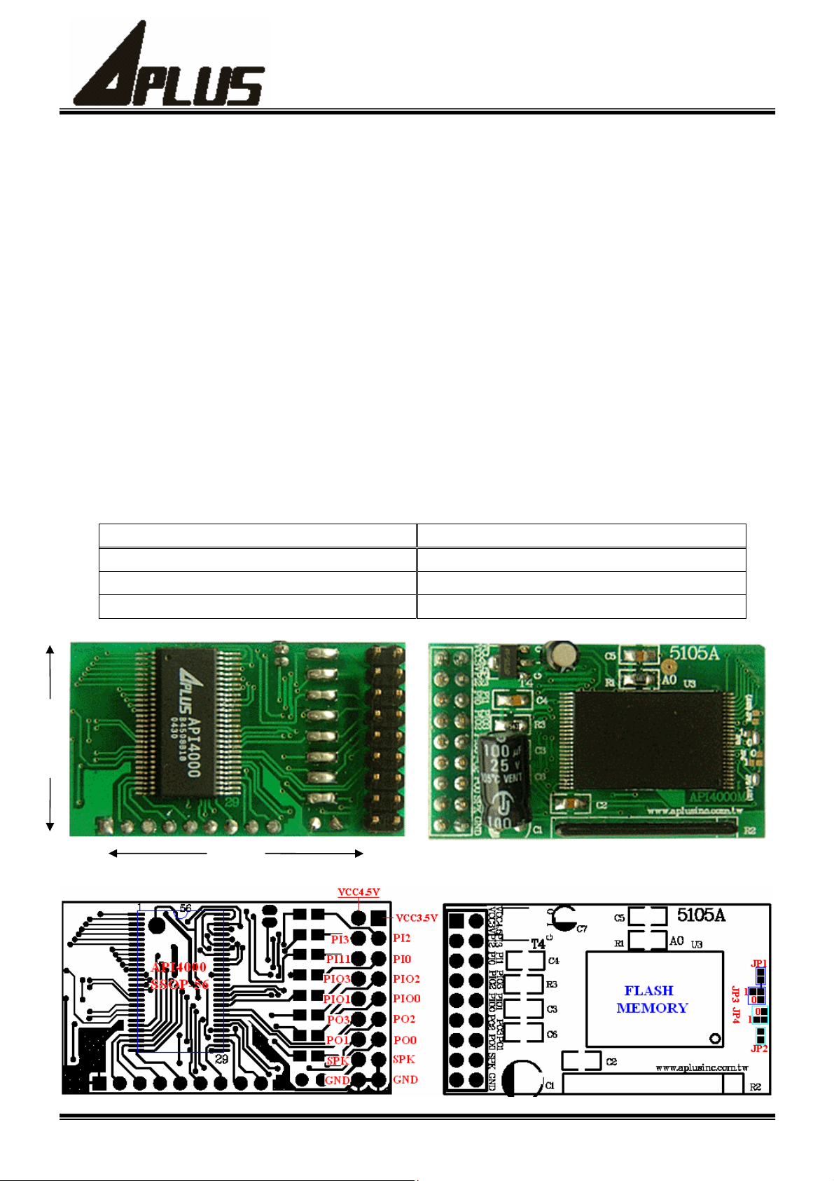
API4000M is a 4-channel Sound Generator which consists of Melody-Controller and Micro-Controller.
API4000M can directly drive Speaker by the Power Amplifier inside, It has 12 I/O Ports connect with other units.
API4000M give 24Bit parallel Address Bus and 8Bit parallel Data Bus for connecting with the Memory from
outside, it can process data maximum 128M bits, it commendatory apply to the product which use high quality
voice and music synthesizer.
FEATURE
*. 4-channel Sound Generator with Melody
*. VCC = 2.7V ~ 5V
*. 4bit ADPCM
*. 24bit Address Bus, 8bit Data Bus
*. 42 Instruction Set
*. 12 Input/Output Data Port
*. Built-In Power Amplifier
PART NO. VOICE DURATIONS
25mm
API4000M2 22 min.
API4000M4 44 min.
API4000M8 88 min.
42mm
1
Page 2
INTEGRATED API4000M SERIES
CIRCUITS INC. VOICE OTP MODULE
ABSOLUTE MAXIMUM RATING
Supply Voltage ( VDD to GND ) ------------------ 5V
Input Voltage Range ------------------ (GND- 0.3V) to (VDD + 0.3V)
Operating Temperature Range ------------------ 0℃ to +60℃
ELECTRICAL CHARACTERISTICS
( VDD=4.5V , GND=0V ,Ta=+25℃ , unless otherwise noted )
PARAMETER CONDITIONS MIN TYP MAX UNITS
Standby Current Chip Shut Down 10 uA
Operating Current Sound On 8 ohm Speaker 50 mA
Input low voltage Input Pins exclude AmpIn 0.8 V
Input high voltage Input Pins exclude AmpIn 3.2 V
output low voltage Iout = -0.1mA for Output Pins 0.5 V
output high voltage Iout = 0.1mA for Output Pins 3.8 V
PIN DESCRIPTION
NO Pin Name Description
1 VDDD Digital Positive Power Supply
2 VDDA Analog Positive Power Supply
3 GNDD Digital Negative Power Supply
4 GNDA Analog Negative Power Supply
5 AMPOUT Power Amplifier Output
6 AMPIN Power Amplifier Input
7 OSC1 Oscillator Input
8 OSC2 Oscillator Output
9 PI3 Data Input Pin
10 PI2 ~ PI0 Data Input/Output Pins
11 PIO3 ~ PIO0 Data Input/Output Pins
12 PO3 ~ PO0 Data Output Pins
13 CEN Memory Chip Enable Pin , Low Active
14 OEN Memory Data Out Enable Pin , Low Active
15 D7 ~ D0 Memory Data Input Pins
16 A23 ~ A0 Memory Address Output Pins
2
Page 3
INTEGRATED API4000M SERIES
CIRCUITS INC. VOICE OTP MODULE
Functional Description
A. Micro–Controller
The Micro-Controller inside API4000M is a 8Bit Processor, it has 2 groups Data Bank each has 16 X 8
Bit Register, the Function for processing Data: Addition , Subtraction , logical AND , Moving , Shift and
the other Basic Function. It also has Address Jump , Data Input , Data Output , Sound Control , Melod
yControl and the other Advanced Function.
Here is the list of 42 instruction in API4000M, each instruction has its Format and Description.
1. JUMP
Instruction Format Code Cycle Bytes
JUMP INTR1, Pn ﹔
JUMP INTR2, Pn ﹔
JUMP INTR3, Pn ﹔
JUMP INTR4, Pn ﹔
JUMP ADDR, Pn ﹔
JUMP CO0, Pn ﹔
JUMP CO1, Pn ﹔
PS :
(1). Code : Code of instruction.
(2). Cycle : Time to executive instruction, 1Cycle = 64 clock period.
(3). Bytes : Size of instruction, 1 Byte = 8 Bits.
(4). Pn ﹕Address in Program, e.g. P123;n = 0 ~ 9999.
(5). INTR1 ﹕Key In signal.
(6). INTR2 ﹕Song End signal.
(7). INTR3 ﹕Sound End signal.
(8). INTR4 ﹕Change Instrument signal.
01 2 3
02 2 3
03 2 3
04 2 3
05 2 3 Program Address(PC) direct jump to Pn.
06 2 3
07 2 3
2. Register & Data
Instruction
if INTR1 = 1, Program Address(PC) will jump to Pn.
if INTR2 = 1, Program Address (PC)will jump to Pn.
if INTR3 = 1, Program Address (PC)will jump to Pn.
if INTR4 = 1, Program Address(PC) will jump to Pn.
if carry out = 0,Program Address(PC) will jump to Pn.
if carry out = 1,Program Address(PC) will jump to Pn.
Description
Instruction Format Code Cycle Bytes Instruction Description
ADDC Rn, Data ﹔
ADDD Rn, Data ﹔
ANDD Rn, Data ﹔
MOVD Rn, Data ﹔
SUBDC Rn, Data ﹔
SUBD Rn, Data ﹔
PS :
(1). Rn ﹕Number of Register,e.g. R3;n = 0 ~ 15.
(2). Data ﹕a decimal value during 0 ~ 255.
6n 1 2
7n 1 2 Rn ÍRn + Data
4n 1 2
5n 1 2 set Rn Í Data.
En 1 2
Fn 1 2 Rn Í Rn - Data
The value of Rn adds Data,only set Carry but don’t
change the value of Rn. ( Rn + Data ÎC=?)
The value of Rn logical AND Data,set the solution
to Rn. ( Rn Í Rn AND Data)
The value of Rn subduct Data, only return Carry
but don’t change the value of Rn.(Rn-DataÎC?)
3
Page 4
INTEGRATED API4000M SERIES
CIRCUITS INC. VOICE OTP MODULE
3. Single Register Operation
Instruction Format Code Cycle Bytes Instruction Description
SHIFTL Rn ﹔
SHIFTR Rn ﹔
DEC Rn ﹔
INC Rn ﹔
2n 1 1
3n 1 1
An 1 1
Bn 1 1
Each Bit of Rn Shift to left Bit,shift 0 to D0.
i.e. D7←D6←D5←D4←D3←D2←D1←D0←0.
Each Bit of Rn Shift to right Bit,shift 0 to D7.
i.e. 0→D7→D6→D5→D4→D3→D2→D1→D0.
The value of Rn subduct 1,set the solution to Rn. (RnÍRn-1)
The value of Rn add 1,set the solution to Rn.(RnÍRn+1)
4. Operation between two Registers
Instruction Format Code Cycle Bytes Instruction Description
ADDR Rn, Rm ﹔
ADDRI Rn, Rm ﹔
ADDRC Rn, Rm ﹔
SUBR Rn, Rm ﹔
SUBRI Rn, Rm ﹔
SUBRC Rn, Rm ﹔
ANDR Rn, Rm ﹔
MOVR Rn, Rm ﹔
D0 2 2 Rn add Rm, set the amount to Rn..(Rn,ÍRn+Rm)
D1 2 2
D2 2 2
D4 2 2
D5 2 2
D6 2 2
D8 2 2
D9 2 2 Set the value of Rm to Rn. ( RnÍRm)
Rn add Rm and Carry, set the amount to Rn. (RnÍRn+Rm+C)
Rn add Rm, only set Carry but don’t change the value
of Rn and Rm. (Rn+Rm Î C?)
Rn subduct Rm, set the difference to Rn. (Rn,ÍRn-Rm)
Rn subduct Rm and Carry, set the difference to Rn.
(Rn ÍRn-Rm-C)
Rn subduct Rm, only set Carry but don’t change the
value of Rn and Rm. (Rn-Rm Î C?)
Rn logical AND Rm, set the solution to Rn.
(RnÍRn AND Rm)
5. Sound & Melody Control
Instruction Format Code Cycle Bytes Instruction Description
LDSPADB Cn, Sn ﹔
LDSPADF Cn, Sn ﹔
LDMYAD Mn ﹔
PLAYSP Cn, Data ﹔
TEMPO Rn ﹔
GAIN Rn ﹔
PS :
(1). Cn ﹕Code of Channel, n = 1A , 1B , 2A , 2B , 3A , 3B , 4A , 4B.
(2). Sn ﹕Code of Sound,sort by sequence,n = 0 ~ 9999.
(3). Mn ﹕Code of Melody Song, sort by sequence n = 0 ~ 9999.
(4). Data : Code of Sound Sample Rate, the value is during 0 ~ 31, reference B.Sound Processor to get
more description.
(5). Reference C. Melody Processor to get more description of Tempo Code.
(6). Volume is during 0 ~ 63,0 is mute,63 is MAX volume.
1n 2 4 Set the start address of Sound.
9n 2 4 Set the end address of Sound.
CF 2 4 Set the start address of Melody.
CE 2 3 Play Sound(PS4).
8E 1 2 Set Rn to Tempo value of Melody (PS5).
8F 1 2 Set Rn to the volume of output sound (PS6).
4
Page 5

INTEGRATED API4000M SERIES
CIRCUITS INC. VOICE OTP MODULE
6. Input & Output Data
Instruction Format Code Cycle Bytes Instruction Description
INPUT PA, Rn ﹔
INPUT PB, Rn ﹔
INPUT PC, Rn ﹔
OUT PA, Rn ﹔
OUT PB, Rn ﹔
OUT PC, Rn ﹔
OUT PD, Rn ﹔
OUT PE, Rn ﹔
PS :
(1). PA , PB , PC , PD , PE is Data Port A , B, C, D, E, Reference D. Data Port to get more description.
80 1 2 Set Data Port A to Rn.( Rn ÍPA)
81 1 2 Set Data Port B to Rn. ( Rn ÍPB)
82 1 2 Set Data Port C to Rn. ( Rn ÍPC)
88 1 2 Set the value of Rn to Data Port A. (PAÍRn)
89 1 2 Set the value of Rn to Data Port B. (PBÍRn)
8A 1 2 Set the value of Rn to Data Port C. (PCÍRn)
8B 1 2 Set the value of Rn to Data Port D. (PDÍRn)
8C 1 2 Set the value of Rn to Data Port E. (PEÍRn)
7. System Control
Instruction Format Code Cycle Bytes Instruction Description
CLINTR ﹔
INTRE ﹔
SHUTDN ﹔
PS : (1). Before executiving SHUTDN Instruction, be sure to executive INTRE Instruction first to assure system
can be restarted after shutdown.
C8 1 1 Clear Interrupt Signal
C9 1 1 Make system can receive interrupt signal.
CA 1 1 System shutdown.
B. Sound Processor
Sound Processor of API4000M use 4 bits ADPCM construction, it has 4 Sound Channel can play music
mixed by 4 different type sound.Sample Rate of Sound is during 4KHz ~ 32Khz, each Channel can has different
Sample Rate.Each Channel has 2 group Address Register for Sound Data, each group Address Register has a Start
Address Register and a End Address Register for Sound Data. Each Sound Channel can be Controlled by
Instruction PLAYSP, or Controlled by Melody Processor.Before Play Sound, Address of Sound Data must be set
first. The following is the description about setting with Channel, Address, and Sample Rate.
1. Channel :
Cn is the no. of Channel in Instruction LDSPADB, LDSPADF, and PLAYSP. Each Channel has A and B
2 group, A and B can’t play together. The folloeing is the Table.
Table B.1
Channel CH1 CH2 CH3 CH4
Group A B A B A B A B
Cn C1A C1B C2A C2B C3A C3B C4A C4B
5
Page 6

INTEGRATED API4000M SERIES
CIRCUITS INC. VOICE OTP MODULE
2. Address :
Sn is the no. of Sound in Instruction LDSPADB and LDSPADF, which is mean the Start Address and End
Address of Memory Sound Data. When Sound is Coding, compiler (API4000SE) will define Address of each
Sound, the Address can be used when program is compiling. If you want to set Address of Sound, just choice the
no. of Sound.
3. Sample Rate :
Data in Instruction PLAYSP is mean Code of Sample Rate, each code is equivalent a Sample Rate. There is
32 type Sample Rate during 4KHz to 32KHz, there is a C.2 Pitch Table in C.Melody Processor.
4. e.g.﹕
LDSPADB C1A , S9 ; /* Set CH1A to Start Address of Sound9 */
LDSPADF C1A , S9 ; /* Set CH1A to End Address of Sound9 */
PLAYSP C1A , 19 ; /* Play Sound9 on CH1, Sample Rate is 16KHz */
LDSPADB C2B , S21 ; /* Set CH2B to Start Address of Sound21 */
LDSPADF C2B , S21 ; /* Set CH2B to End Address of Sound21 */
PLAYSP C2B , 19 ; /* Play Sound21 on CH2,Sample Rate is 16KHz */
LDSPADB C3A , S123 ; /* Set CH3A to Start Address of Sound123 */
LDSPADF C3A , S123 ; /* Set CH3A to End Address of Sound123 */
PLAYSP C3A , 0 ; /* Play Sound123 on CH3, Sample Rate is 4KHz */
LDSPADB C4B , S888 ; /* Set CH4B to Start Address of Sound888 */
LDSPADF C4B , S888 ; /* Set CH4B to End Address of Sound888 */
PLAYSP C4B , 0 ; /* Play Sound888 on CH4, Sample Rate is 4KHz */
C. Melody Processor
Melody Processor inside API4000M use Wave Table construction to simulate the tone from musical
instrument, It can coinstantaneous play 4 Channel. Each Channel has 2 banks Wave Table, A group is reference
Address of treble tone, B group is reference Address of bass tone. treble tone range is during B3(71) ~ B4(83),
reference value is B3(71); bass tone range is during E1(40) ~ A#3(70), reference value is A#2(58). Each Melody
st
Note Data is in 2 byte form, 1
byte consists of 5bits Pitch Data, 1 bit Bank Data, and 2bits Control Data. Melody Processor can processor 32 type
Beats, There is a Beat Table on Table C.1.
All processible Pitch range is during E1(40) ~ B4(83), total 36 type Note, Table C.2 is a list about Pitch Data,
Note, and Sample Rate. Tempo of Melody is set by Function TEMPO Rn, the value of Rn is from Code value of
Tempo, Table C.3 is about their reference.
Instruction LDMYAD Mn is used to set Start Address of Melody Data in Memory, Mn is the Code of Melody,
As Melody compiling, compiler(API4000ME) will define Data Address of each Melody, Data Address can be use
in coding. You can use Melody Code to set Address of Melody.
Melody’s playing is controlled by Instruction OUT PE, Rn, There is description about how to control in
D.Input & Output Data. Melody’s change instrument and end signal is defined in Melody Data, it will active 2
interrupt signal “Change Instrument” and “Song End”, if program detects such signal, it will do correspondent
action.
byte consists of 5bits Beat Data, 2bits Channel Data, and 1 bit Control Data, 2nd
6
Page 7

INTEGRATED API4000M SERIES
CIRCUITS INC. VOICE OTP MODULE
C.1 Beat Table :
NO. Beats/sec NO. Beats/sec NO. Beats/sec NO. Beats/sec
0 1/16 8 9/16 16 18/16 24 36/16
1 2/16 9 10/16 17 20/16 25 40/16
2 3/16 10 11/16 18 22/16 26 44/16
3 4/16 11 12/16 19 24/16 27 48/16
4 5/16 12 13/16 20 26/16 28 52/16
5 6/16 13 14/16 21 28/16 29 56/16
6 7/16 14 15/16 22 30/16 30 60/16
7 8/16 15 16/16 23 32/16 31 64/16
C.2 Pitch Table :
Pitch Code
0
1 E1 5.0 17 G#2
2 F1 5.5 18 A2
3 F#1 6.0 19 A#2 B3 16.0
4 G1 6.5 20 B2 C4 17.0
5 G#1 7.0 21 C3 C#4 18.0
6 A1 7.5 22 C#3 D4 19.1
7 A#1 8.0 23 D3 D#4 20.2
8 B1 8.5 24 D#3 E4 21.4
9 C2 9.0 25 E3 F4 22.7
10 C#2 9.5 26 F3 F#4 24.0
11 D2 10.1 27 F#3 G4 25.4
12 D#2 10.7 28 G3 G#4 27. 0
13 E2 11.3 29 G#3 A4 28.6
14 F2 12.0 30 A3 A#4 30.3
15 F#2 12.7 31 A#3 B4 32.0
Note Note
Bank B
—
Fs (KHz) Pitch Code
4.0 16 G2
Bank B Bank A
—
—
—
Fs (KHz)
13.5
14.3
15.1
PS : (1). Pitch Code : 21 , Note number of C3 = 60.
(2). Bank A : treble tone; Bank B : bass tone.
(3). Fs : Sample Rate when Oscillator Frequency of API4000M is 2816KHz.
C.3 Tempo Table
Tempo Code
234 234 152 222 112 210 68 180
224 233 147 221 110 209 64 176
217 232 143 220 107 208 60 170
206 231 139 219 105 207 57 166
198 230 135 218 103 206 53 158
191 229 132 217 101 205 51 154
184 228 129 216 99 204 47 146
177 227 126 215 95 202 43 136
172 226 123 214 89 198 40 126
166 225 120 213 86 196 30 86
161 224 117 212 80 192
156 223 114 211 74 186
PS : (1). The value of Tempo when Oscillator Frequency of API4000M is 2816KHz.
Tempo Code
Tempo Code Tempo Code
7
Page 8

INTEGRATED API4000M SERIES
CIRCUITS INC. VOICE OTP MODULE
D. Input & Output Data
By the 2 Instruction INPUT and OUTPUT, Data can pass inside API4000M, or connect with outside. The
following is the description about each Data Port’s act.
1. Input Data Port
(1) PA ﹕Input Data Port A is a value consists of Input Pin PIO3 ~ PIO0 and PI3 ~ PI0, Following is their
correspondent.
PA bit7 bit6 bit5 bit4 bit3 bit2 bit1 bit0
Input Pin PIO3 PIO2 PIO1 PIO0 PI3 PI2 PI1 PI0
PS ﹕If PIO3 ~ PIO0 or PI2 ~ PI0 are set to Out Pin, bit7 ~ bit4 or bit2 ~ bit0 will be Unknown State.
(2) PB ﹕Input Data Port B can make Melody change Channel code of instrument and Instrument Code,
Each bit of PB has following act.
PB bit7 bit6 bit5 bit4 bit3 bit2 bit1 bit0
Item - C1 C0 Inst4 Inst3 Inst2 Inst1 Inst0
PS﹕
(1). Inst4~Inst0 ﹕Code of Instrument, 0 ~ 31 total 32 type, set as Melody Compiling.
(2). C1,C0 ﹕Code of Channel﹔
C1=1,C0=1 is CH1 ﹔
C1=0,C0=0 is CH2 ﹔
C1=0,C0=1 is CH3 ﹔
C1=1,C0=0 is CH4 ﹔
(3) PC ﹕Input Data Port C is display End State of each channel, each pin of PC has following act.
PC bit7 Bit6 bit5 bit4 bit3 bit2 bit1 bit0
Item - - - - Sn4 Sn3 Sn2 Sn1
PS﹕ (1). Sn4 , Sn3 , Sn2 and Sn1 displayed Channel CH4 , CH3 , CH2 and CH1 if had happen Sound End,
state 1 means Soind End.
2. Output Data Port
(1) PA ﹕Output Data Port A consists of Output Pin PIO3 ~ PIO0 and PO3 ~ PO0, each bit of PA after
API4000M
power on, the initial state is 0, each pin of PA has following act.
PA bit7 bit6 bit5 bit4 bit3 bit2 bit1 bit0
Output Pin PIO3 PIO2 PIO1 PIO0 PO3 PO2 PO1 PO0
PS ﹕If PIO3 ~ PIO0 are set to Input Pin, bit7 ~ bit4 will not affect PIO3 ~ PIO0 of state.
8
Page 9

INTEGRATED API4000M SERIES
CIRCUITS INC. VOICE OTP MODULE
(2) PB ﹕Output Data Port B consists of Output Pin PI2 ~ PI0, each pin of PB has following act.
PB bit7 bit6 bit5 bit4 bit3 bit2 bit1 bit0
Output Pin - - - - - PI2 PI1 PI0
PS ﹕If PI2 ~ PI0 are set to Input Pin, bit2 ~ bit0 will not affect PI2 ~ PI0 of state.
(3) PC ﹕Output Data Port C can set Each Pin’s act of PIO3 ~ PIO0, Following is their correspondent.
bit7 bit6 PIO3 bit5 bit4 PIO2
0 0 Pull-low Input Pin, no input trigger. 0 0 Pull-low Input Pin, no input trigger.
0 1 Pull-low Input Pin, with input trigger. 0 1 Pull-low Input Pin, with input trigger.
1 0 Floating Input Pin, no input trigger. 1 0 Floating Input Pin, no input trigger.
1 1 Output Pin. 1 1 Output Pin.
Bit3 bit2 PIO1 bit1 bit0 PIO0
0 0 Pull-low Input Pin, no input trigger. 0 0 Pull-low Input Pin, no input trigger.
0 1 Pull-low Input Pin, with input trigger. 0 1 Pull-low Input Pin, with input trigger.
1 0 Floating Input Pin, no input trigger. 1 0 Floating Input Pin, no input trigger.
1 1 Output Pin. 1 1 Output Pin.
PS ﹕Each bit of PC after API4000M power on, initial state is 0.
(4) PD ﹕Output Data Port D can choice Data Bank, set Operate Voltage, set each pin of PO3 ~ PO0 and PI3 ~ PI0
function, following is their correspondent.
(a) bit7 not use, bit6 must set to 0.
(b) bit5 = 0, Operate Voltage is 4.5V﹔bit5 =1, Operate Voltage is 3.0V.
(c) bit4 = 0, disable PO3 ~ PO0 each Pin’s output﹔bit4 = 1, enable PO3 ~ PO0 each Pin’s output.
(d) bit3 = 0, set PI2 ~ PI0 to Input Pin ﹔bit3 = 1, set PI2 ~ PI0 to Output Pin.
(e) bit2 = 0 set PI3 to Pull-low Input Pin ﹔bit2 = 1 set PI3 to Floating Input Pin.
(f) bit1 = 0 set PI2 ~ PI0 to Pull-low Pin ﹔bit1 = 1 set PI2 ~ PI0 to Floating Pin.
(g) bit0 = 0 set Data Bank to group A of 16 registers ﹔bit0 = 1 set Data Bank to group B of 16 registers.
(h) Each bit of PD after API4000M power on, initial state is 0.
(5) PE ﹕Output Data Port E can set Sound and Melody’s operate mode, the following is description.
(a) bit7 must set 0.
(b) bit6 = 0, Sound Processor Off ﹔bit6 = 1, Sound Processor On.
(c) bit5 = 0, Melody Off ﹔bit5 = 1, Melody Start and On.
(d) bit4 = 0,no action ﹔bit4 = 1,Off Melody Channels.
(e) bit3 = 0, CH4 is Sound Mode ﹔bit3 = 1, CH4 is Melody Mode.
(f) bit2 = 0, CH3 is Sound Mode ﹔bit2 = 1, CH3 is Melody Mode.
(g) bit1 = 0, CH2 is Sound Mode ﹔bit1 = 1, CH2 is Melody Mode.
(h) bit0 = 0, CH1 is Sound Mode ﹔bit0 = 1, CH1 is Melody Mode.
(i) After API4000M shut down, Each bit of PE will reset to 0.
9
Page 10

INTEGRATED API4000M SERIES
CIRCUITS INC. VOICE OTP MODULE
E. Memory Data Structure
Program Data, Melody Data, Sound Data of API4000M all input from outside, Each group Data are 8 bits,
Input from 8 Memory Data Input Port D7 ~ D0. API4000M can direct control 24bits Memory Address, output from
24 Memory Address Output Port A23 ~ A0. Data in Memory is in order of Program Data, Melody Data, Sound
Data. Program Data’s Start Address is 000000, Max. Address is 00FFFF, Program Data has max. 64K Bytes.
Melody Data’s Start Address is continue from Program Data’s End Address, Sound Data’s Start Address is
continue from Melody Data’s End Address, Highest Address is FFFFFF.
PROGRAM GUID
API4000M is controlled by Program to Play Sound or Play Melody, this chapter will descript how to write
a Program.
A. Initial State
After API4000M Power On, or wake up again after Shut Down, Program Data Address of API4000M is set
on Address 000000. You can use instruction OUTPC, OUTPD in the program’s first to set Pin act of PI3 ~ PI0,
PIO3 ~ PIO0, and PO3 ~ PO0. Every register in Data Bank after Power On has random initial value, but Shut
Down won’t change the value.
B. Play Sound
Before Playing Sound, Start Address and End Address of Sound Data which would be played must set on the
Channel want Play Sound. Use Instruction LDSPADB and LDSPADF set Address of Sound Data. Otherwise, the
Channel must be set to Sound Mode by Data Port PE, Sound Processor must be set on, and use Instruction CLINTR
to clear residual INTR3 interrupt signal . Then use Instruction PLAYSP to begin playing sound, use INTR3 to
detect interrupt signal, and use Instruction INPUT PC to detect the Sound had play over or not. The channel who
doesn’t play sound must be set to Melody Mode in Data Port PE, avoid mistake Sound End interrupt signal;
exercise Instruction CLINTR, or set Sound Processor to OFF, will clear interrupt signal INTR3.
C. Play Melody
Before Play Melody, except set Sound Data Address to decide instrument, Address of Melody Data also must
be set by Instruction LDMYAD, and set value of Melody Tempo, then use Instruction OUT PE set the channel
would play to Melody Mode, set Sound Processor ON, trigger to play Melody. When Melody playing, if the
interrupt signal INTR4(Change Instrument) be detected, use Instruction INPUT PB to decision which channel need
change instrument, reset trible/bass tone reference Sound Data Address of the channel directly. Melody play over
will send a interrupt signal INTR2(Song End), If you want pause or stop play Melody play, use Instruction
OUT PE to set Melody to OFF.
10
Page 11

INTEGRATED API4000M SERIES
CIRCUITS INC. VOICE OTP MODULE
D. External Interface
PI3 ~ PI0 , PIO3 ~ PIO0 , and PO3 ~ PO0 is the link for API4000M connecting with outside, Instruction
INPUT PA, OUT PA, or OUT PB, can input or output Data. PI3 , or PI2 ~ PI0 that set to Input Pin, or PIO3 ~ PIO0
of Input Pin set with Trigger has any pin is High Level, there will send a interrupt signal INTR1(Key In), and Wake
Up API4000M in Shut Down. Before exercising Instruction SHUTDN, must exercise Instruction INTRE first, then
API4000M can Wake Up again.
E. Sample Program
MOVD R2 , 85 ; /* R2 = 01010101 */
OUT PC , R2 ; /* Set PIO3 ~ PIO0 to Trigger Input Pins */
MOVD R5 , 50 ; /* R5 = 50 */
GAIN R5 ; /* Set volume Level to 50 */
LDSPADB C1A , S9 ; /* Set Start Address of Sound9 on CH1A */
LDSPADF C1A , S9 ; /* Set End Address of Sound9 on CH1A */
MOVD R3 , 78 ; /* R3 = 01001110 */
OUT PE , R3 ; /* Set CH1 = Sound Mode, Sound Processor = ON */
CLINTR ; /* Cleat interrupt signal INTR */
PLAYSP C1A , 19 ; /* Sample Rate 16KHz , Play Sound9 on CH1 */
P1:
JUMP INTR3 , P2 ; /* if Sound End go to P2 */
JUMP ADDR , P1 ; /* go to P1 */
P2:
MOVD R3 , 15 ; /* R3 = 00001111 */
OUT PE , R3 ; /* Set CH1 = Melody Mode, Sound Processor = OFF */
LDSPADB C1B , S11 ; /* Set Start Address of Sound11 on CH1B */
LDSPADF C1B, S11 ; /* Set End Address of Sound11 on CH1B */
LDSPADB C1A , S12 ; /* Set Start Address of Sound12 on CH1A */
LDSPADF C1A , S12 ; /* Set End Address of Sound12 on CH1A */
LDSPADB C2B , S11 ; /* Set Start Address of Sound11 on CH2B */
LDSPADF C2B , S11 ; /* Set End Address of Sound11 on CH2B */
LDSPADB C2A , S12 ; /* Set Start Address of Sound12 on CH2A */
LDSPADF C2A , S12 ; /* Set End Address of Sound12 on CH2A */
LDSPADB C3B , S13 ; /* Set Start Address of Sound13 on CH3B */
LDSPADF C3B , S13 ; /* Set End Address of Sound13 on CH3B */
LDSPADB C3A , S14 ; /* Set Start Address of Sound14 on CH3A */
LDSPADF C3A , S14 ; /* Set End Address of Sound14 on CH3A */
LDSPADB C4B , S15 ; /* Set Start Address of Sound15 on CH4B */
LDSPADF C4B , S15 ; /* Set End Address of Sound15 on CH4B */
LDSPADB C4A , S16 ; /* Set Start Address of Sound16 on CH4A */
LDSPADF C4A , S16 ; /* Set End Address of Sound16 on CH4A */
LDMYAD M0 ; /* Set Start Address of Melody Song 0 */
11
Page 12

INTEGRATED API4000M SERIES
CIRCUITS INC. VOICE OTP MODULE
MOVD R7 , 204 ; /* R7 = 204 */
TEMPO R7 ; /* Set Tempo = 99 */
MOVD R0 , 111 ; /* R0 = 01101111 */
OUT PE , R0 ; /* SetSound Processor = ON,Melody = ON,CH4 ~ CH1 to Melody Mode */
P5:
JUMP INTR1 , P40 ; /* if Key In go to P40 */
JUMP INTR2 , P30 ; /* if Song End go to P30 */
JUMP INTR4 , P20 ; /* if Change Instrument go to P20 */
JUMP ADDR , P5 ; /* go to P5 */
P20:
INPUT PB , R8 ; /* read data about changing instrument */
CLINTR ; /* clear INTR4 */
ADDC R8 , 224 ; /* if R8 < 32 */
JUMP CO0 , P22 ; /* if CH2 go to P22 */
ADDC R8 , 192 ; /* if R8 < 64 */
JUMP CO0 , P23 ; /* if CH3 go to P23 */
ADDC R8 , 160 ; /* if R8 < 96 */
JUMP CO0 , P24 ; /* if CH4 go to P24 */
P21:
LDSPADB C1B , S21 ; /* Set Start Address of Sound21 on CH1B */
LDSPADF C1B , S21 ; /* Set End Address of Sound21 on CH1B */
LDSPADB C1A , S22 ; /* Set Start Address of Sound22 on CH1A */
LDSPADF C1A , S22 ; /* Set End Address of Sound22 on CH1A */
JUMP ADDR , P5 ; /* go to P5 */
P22:
LDSPADB C2B , S31 ; /* Set Start Address of Sound31 on CH2B */
LDSPADF C2B , S31 ; /* Set End Address of Sound31 on CH2B */
LDSPADB C2A , S32 ; /* Set Start Address of Sound32 on CH2A */
LDSPADF C2A , S32 ; /* Set End Address of Sound32 on CH2A */
JUMP ADDR , P5 ; /* go to P5 */
P23:
LDSPADB C3B , S33 ; /* Set Start Address of Sound33 on CH3B */
LDSPADF C3B , S33 ; /* Set End Address of Sound33 on CH3B */
LDSPADB C3A , S34 ; /* Set Start Address of Sound34 on CH3A */
LDSPADF C3A , S34 ; /* Set End Address of Sound34 on CH3A */
JUMP ADDR , P5 ; /* go to P5 */
P24:
LDSPADB C4B , S25 ; /* Set Start Address of Sound25 on CH4B */
LDSPADF C4B , S25 ; /* Set End Address of Sound25 on CH4B */
LDSPADB C4A , S26 ; /* Set Start Address of Sound26 on CH4A */
LDSPADF C4A , S26 ; /* Set End Address of Sound26 on CH4A */
JUMP ADDR , P5 ; /* go to P5 */
12
Page 13

INTEGRATED API4000M SERIES
CIRCUITS INC. VOICE OTP MODULE
P30:
MOVD R0 , 15 ; /* R0 = 00001111 */
OUT PE , R0 ; /* Set Sound Processor = OFF, Melody = OFF */
CLINTR ; /* clear INTR2 */
JUMP ADDR , P50 ; /* go to P50 */
P40:
INPUT PA , R12 ; /* read Input Port A data */
ADDC R12 , 254 ; /* if R12 < 2 */
JUMP CO0 , P42 ; /* if PI0 = 1 go to P42 */
P41:
JUMP INTR1 , P41 ; /* if Key In go to P41 */
JUMP ADDR , P5 ; /* go to P5 */
P42:
JUMP INTR1 , P42 ; /* if Key In go to P42 */
MOVD R0 , 15 ; /* R0 = 00001111 */
OUT PE , R0 ; /* Set Sound Processor = OFF, Melody = OFF */
P50:
INTRE ; /* enable INTR signal */
SHUTDN ; /* Shut Down API4000M */
END ; /* End of Program , END must put in the end of program */
13
Page 14

INTEGRATED API4000M SERIES
CIRCUITS INC. VOICE OTP MODULE
TYPICAL APPLICATION CIRCUIT
14
Page 15

INTEGRATED API4000M SERIES
CIRCUITS INC. VOICE OTP MODULE
API4000 SSOP-56 PIN(300MIL) PACKAGE :
15
 Loading...