

Page 1
The Intelligent Use of Water™
Page 2
Design, Installation and Maintenance Guide
INDEX | TABLE OF CONTENTS
SECTION 1 INTRODUCTION ...........................................3
About Rain Bird / The Intelligent Use of Water ...............5
Leed Library ................................................6
Benets of Dripline Irrigation ...............................7
SECTION 2 PREPARATION FOR DESIGN ..............................8
XF Series Dripline | Where is it used? ........................9
Preparation for Design .................................... 10
Determine Soil Type ...................................... 11
SECTION 3 DETERMINE DRIPLINE SPECIFICATIONS ................12
SECTION 4 DETERMINE TYPE OF DRIPLINE LAYOUT ...............14
End Feed / Center Feed ................................... 15
Loop / Curved Edge ...................................... 16
Branching Out or Joining Row ............................ 17
Slopes ...................................................18
Determine Lateral Row Spacing ........................... 19
SECTION 5 ZONE WATER CALCULATIONS .......................... 20
Calculating Zone Water Requirements .................... 21
Calculating Application Rates ............................. 22
Calculations for Dripline Irrigation ........................23
Irrigation Formulas ....................................... 24
SECTION 6 DRIPLINE MODELS FOR EVERY APPLICATION .......... 25
XFS-CV Dripline for On/Subsurface Elevated Applications . . . . . . 26
XFS-CV Dripline - Specications ........................... 27
XFCV Dripline for On-Surface Elevated Applications ........... 28
XFCV Dripline - Specications ............................. 29
XFS Dripline for Subsurface Applications ..................... 30
XFS Dripline - Specications .............................. 31
XFD Dripline for On-Surface - Level Grade Applications ........ 32
XFD Dripline - Specications .............................. 33
1/4” Dripline for Potted/Small Bed Applications .............. 34
SECTION 7 SUBSURFACE DESIGN, INSTALLATION & OPERATION . . . . . . 35
Best Subsurface Applications ............................. 36
Adjust for Trees / Curved Edges ........................... 37
Design for Conned Areas ................................ 38
Design for Large Areas .................................... 39
Installation Methods ................................... 40-41
Recommended Practices .................................42
SECTION 8 SPECIFYING PRODUCTS IN THE ZONE .................. 43
QF Dripline Header .................................... 44-46
Control Zone Kits ......................................... 47
Control Zone Kit Selection Chart ........................... 48
Fittings ................................................49-51
Spray-to-Drip Retrot Kits ................................. 52
Air Relief Valve / Stakes / Flush Point ...................... 53
Drip System Operation Indicator .......................... 54
SECTION 9 FAQ’S, GLOSSARY, AND RESOURCES ................... 55
Preventative Maintenance: Flushing / Winterizing .......... 56
Written Specications and CAD Detail Drawings ........... 57
Frequently Asked Questions ............................ 58-59
Glossary ...............................................60-61
Notes .................................................. 62-63
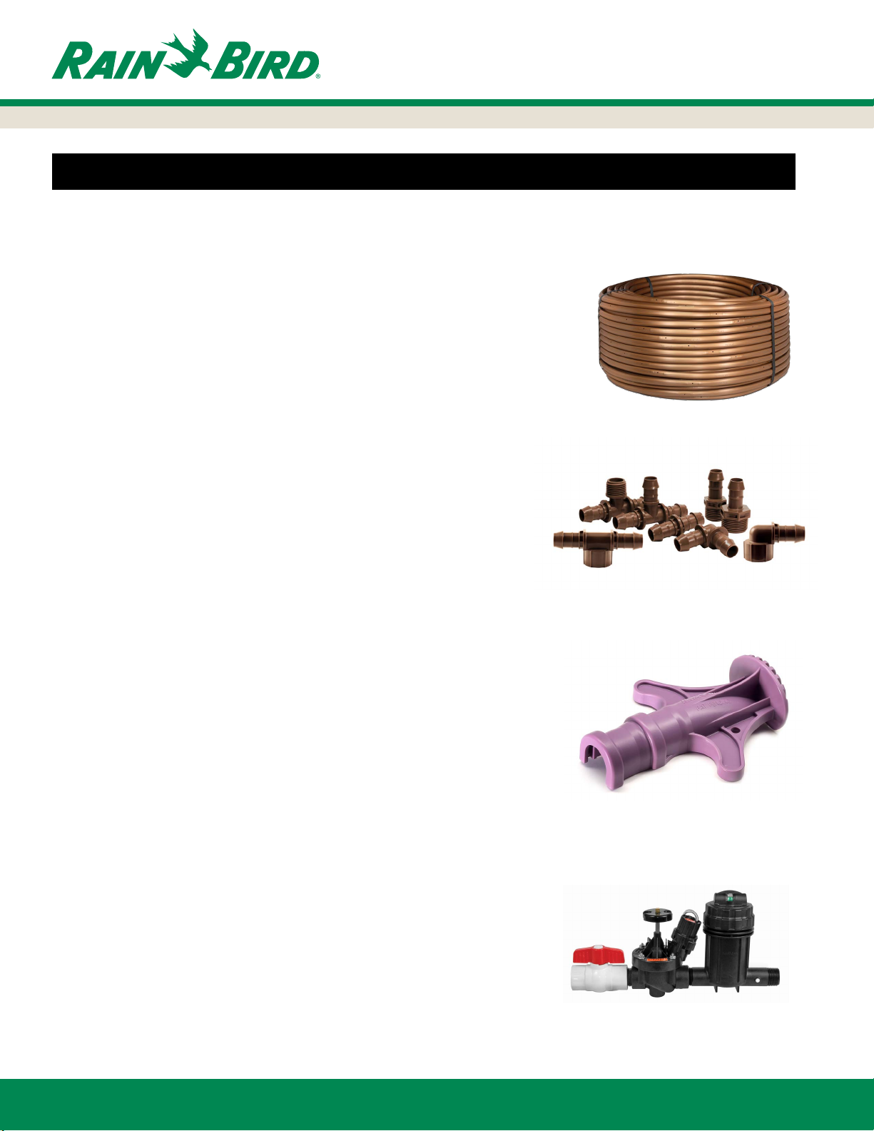
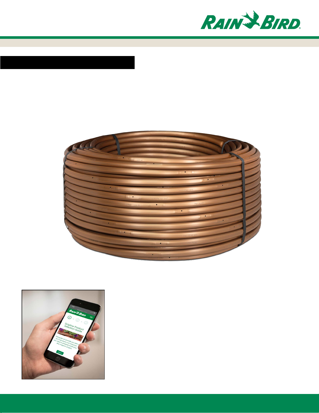
XF Series Dripline
XFS-CV Dripline
17mm XF Insert Fittings
XF Insertion Tool
Subsurface Design, Installation and Operation
Control Zone Kit
2
www.rainbird.com
Page 3
Section 1:
Introduction
SECTION 1: Introduction
This guide covers the basics of design, installation, and maintenance for
Rain Bird’s XF Series Dripline. Included are design steps, technical data,
installation layouts and design details to assist in the design of the more
common dripline applications.
www.rainbird.com
For help selecting the proper XF Series Dripline
products, visit: www.rainbird.com/calculator
Access from your laptop, tablet or smart phone.
For more in-depth resources, visit:
www.rainbird.com/drip
3
Page 4
SECTION 4
SECTION 7
SECTION 2
SECTION 5
SECTION 8
SECTION 3
SECTION 6
SECTION 9
This guide covers the basics of design, installation, and maintenance
for Rain Bird’s XF Series Dripline. Included are design steps, technical
data, installation layouts and design details to assist in the design of
SECTION 1
the more common dripline applications.
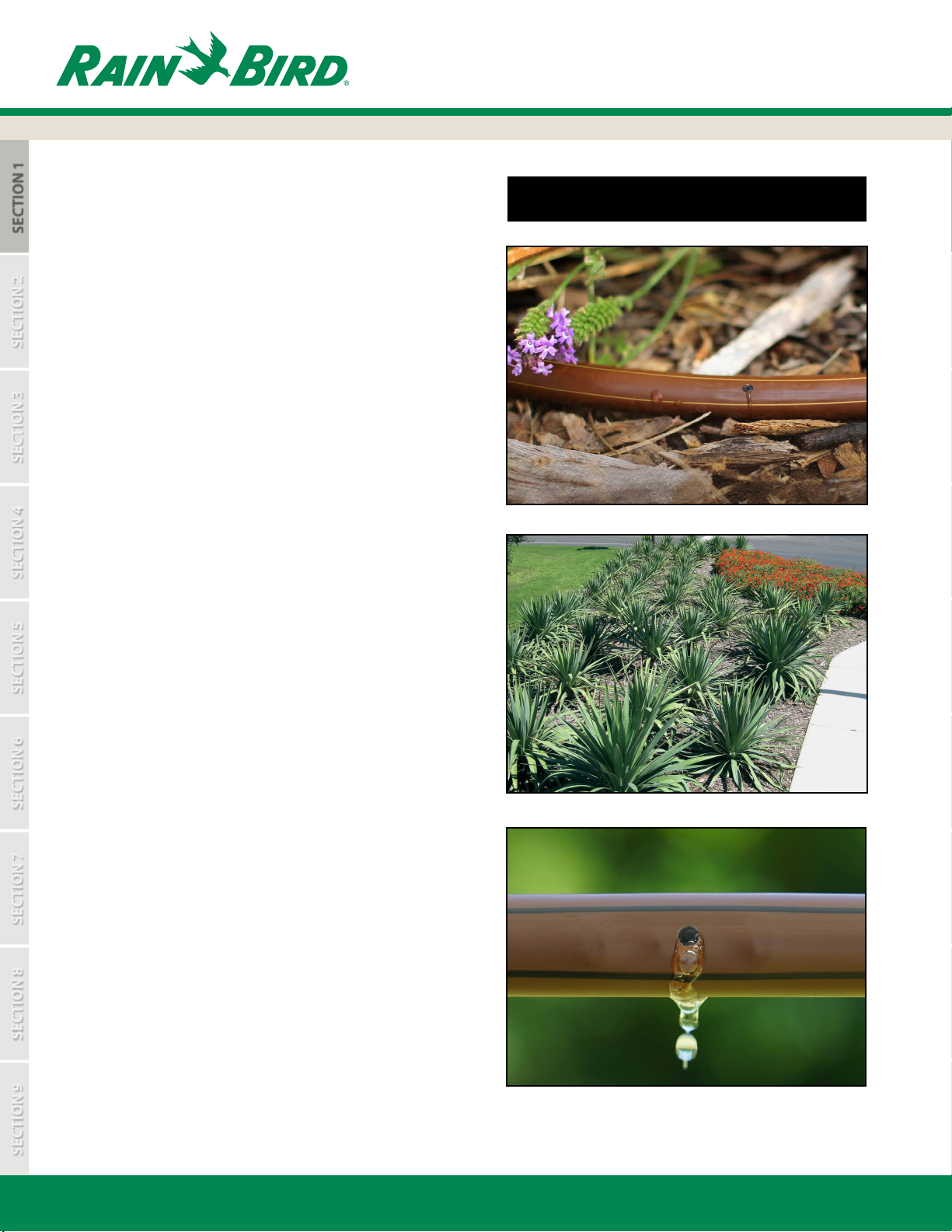
A low volume irrigation system typically applies water slowly, at
low pressure, at or near the root zones of plant material. Whether
referred to as Drip, Xerigation®, micro irrigation, or low volume,
these systems feature emission devices that apply water in gallons
per hour (GPH) or liters per hour (L/HR) as opposed to the gallons
per minute (GPM) or liters per minute (L/MIN) of a conventional
overhead spray irrigation system. Low-volume irrigation can greatly
reduce or eliminate water waste while promoting healthier plant
growth because you can:
• Match the amount of water applied to the specic need
of each plant
• More closely match the application rate to the soil’s
inltration rate
Section 1:
Introduction
SECTION 1: INTRODUCTION
• Apply water directly to the root zone, reducing overspray
and evaporation
Low-volume systems also reduce or eliminate runo on walks and
paved areas, and overspray onto windows, fences, pavement and
walls. The Rain Bird Xerigation® line of drip products oer a full
range of water-saving choices for both turf and non-turf landscape
applications, including control zone components, dripline, ttings,
blank tubing, emission devices and tools.
Use of dripline is a preferred method in many low-volume
irrigation applications. Rain Bird’s XF Series Dripline has Rain Bird
designed and manufactured emitters that provide pressure
compensation for precise ow control throughout the zone.
XF Series Dripline is made with advanced polymers that provide
kink-resistance and reduce coil memory for easier installation.
With emitter ow rates of 0.4 GPH, 0.6 GPH, and 0.9 GPH
(1.6 L/HR, 2.3 L/HR, and 3.4 L/HR) and emitter spacing of 12” and
18” (0.30 m and 0.45 m) the XF Series provides a full product line
to meet the needs of any application.
The Rain Bird XF Series of dripline products consists of:
• XFD –for on-surface applications
• XFCV for on-surface, sloped applications
• XFS with Copper Shield™ Technology
– for subsurface applications
• XFS-CV with Heavy Duty Check Valve
– for on-surface, subsurface and sloped applications
For complete performance and technical specications, please see
Rain Bird’s Landscape Irrigation Products Catalog or visit
Rain Bird’s website at www.rainbird.com. The website provides
specications and detail drawings in downloadable les.
4
XFCV for on-surface, sloped applications.
www.rainbird.com
Page 5
SECTION 4
SECTION 7
SECTION 2
SECTION 5
SECTION 8
SECTION 3
SECTION 6
SECTION 9
– HE-VAN Series Nozzles
Section 1:
Introduction
ABOUT RAIN BIRD AND THE INTELLIGENT USE OF WATER
A privately held company founded in 1933, Rain Bird
Corporation is the leading manufacturer and provider of
irrigation products and services. Since its beginnings, Rain
Bird has oered the industry’s broadest range of irrigation
products for farms, golf courses, nurseries, sports arenas,
commercial developments and homes in more than 130
countries around the world. With the broadest product line
in the industry, architects, designers and contractors
recognize Rain Bird as the industry leader in irrigation
solutions.
Rain Bird is committed to The Intelligent Use of Water™.
It is our legacy to design and manufacture only those
products of the highest value, quality, and ecient
application of water. We work for long-term, responsible
partnerships with our customers and our suppliers. This is
who we are, and this is how we wish to be perceived in the
irrigation industry and our communities.
Please visit The Intelligent Use of Water section of our
website to explore additional resources to help you design
the most water-ecient projects.
http://www.rainbird.com/landscape/resources/IUOW.htm
SECTION 1
Water Source
Need
Preserve potable water through alternative
sourcing that taps into underutilized supplies
such as underground well water, grey
water and rain water.
Rain Bird Solution
• Non-potable-water-ready:
– Drip products
– Valves
– Rotors
– Sprays
MAXIMUM
Design & Manage
Need
Receive support from a certied professional trained to
design, install, operate and maintain a water-ecient system.
Rain Bird Solution
Rain Bird’s Contractor Referral Program helps you quickly and
easily nd a qualied irrigation contractor in your area.
WATER
Apply
Need
Distribute water to your landscape
as eciently as possible.
Rain Bird Solution
• Xerigation®/Landscape Drip: Direct-to-plant-root watering devices.
• Water-smart rotor and spray features:
– Pressure Regulating Stem (PRS) technology
– Seal-A-Matic™ (SAM) check valves
• High-eciency Nozzles:
– Rain Curtain™ Nozzles
– U-Series Nozzles
– Matched Precipitation Rate (MPR) Nozzles
– Square Pattern Nozzles (SQ)
– R-VAN Series Nozzles
EFFICIENCY
Schedule
Need
Flexible programming schedules that help you customize
a watering schedule based on the needs of your landscape.
Rain Bird Solution
Our controllers oer:
• Cycle+Soak feature allowing for
the most ecient water delivery
• Easy, push-of-the-button adjustments
for seasonal changes
• Weather-based controllers which
adjust based on hourly weather data
www.rainbird.com
5
Page 6
SECTION 4
SECTION 7
SECTION 2
SECTION 5
SECTION 8
SECTION 3
SECTION 6
SECTION 9
SECTION 1:
Introduction
LEED LIBRARY
SECTION 1
WHAT IS LEED?
The Leadership in Energy and Environmental Design (LEED) Green Building Rating System™ is a point rating system
devised by the United States Green Building Council (USGBC) to evaluate the environmental performance of a building
over its life cycle and to encourage market transformation towards sustainable design. LEED is the nationally recognized
benchmark for the design, construction, and operation of high performance green buildings. LEED provides building
owners and operators with the tools they need to have an immediate and measurable impact on their buildings’
performance. LEED promotes a whole-building approach to sustainability by recognizing performance in ve key areas
of human and environmental health: sustainable sites, water savings, energy eciency, materials selection, and indoor
environmental quality.
Detailed information on obtaining credits and the project certication process is available from the USGBC on their
website: www.usgbc.org.
DESIGN & TECHNICAL RESOURCES
• WATER EFFICIENCY CREDIT 1.1
• WATER EFFICIENCY LANDSCAPING: Reduce by 50% 2 points
Intent
Limit or eliminate the use of potable water, or other natural surface water resources available on or near the project site,
for landscape irrigation.
Requirements
Reduce potable water consumption for irrigation by 50% from a calculated mid-summer baseline case. Reductions shall
be attributed to any combination of the following items:
• Plant species factor
• Irrigation eciency
• Use of captured rainwater
• Use of recycled wastewater
• Use of water treated and conveyed by a public agency for non-potable uses.
Rain Bird Notes
The designer on the LEED project will need to provide an irrigation plan and legend, as well as calculations, a
description of the baseline, and cut sheets of the irrigation system demonstrating how water consumption is
reduced by 50%.
Learn more at: http://www.rainbird.com/landscape/resources/LEEDlibrary.htm
6
www.rainbird.com
Page 7
SECTION 4
SECTION 7
SECTION 2
SECTION 5
SECTION 8
SECTION 3
SECTION 6
SECTION 9
SECTION 1:
Introduction
SECTION 1
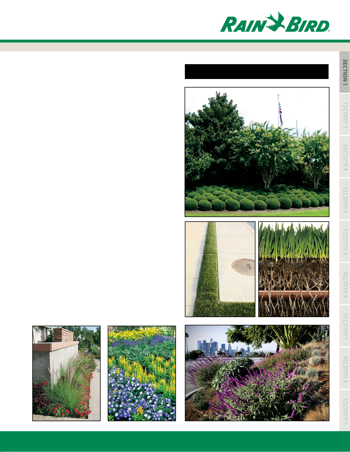
Dripline irrigation can greatly reduce or eliminate water
waste while promoting healthier plant growth for the
following reasons:
• Match the water application to the specic needs of
each plant
• More precisely match the application rate to the soil’s
inltration rate
• Apply water directly to the root zone to reduce
overspray and evaporation
• A properly designed and installed dripline irrigation
system can be over 90% ecient
There are many advantages of dripline irrigation that can
provide solutions for dicult-to-irrigate landscape areas
including:
• Narrow turf areas
• Curved narrow landscape areas
• Sloped areas
• Subsurface turf irrigation applications
• Parking lot islands
• Steep sloped areas
BENEFITS OF DRIPLINE IRRIGATION
Other benets of on-surface or subsurface Drip Irrigation:
• Eliminate runo on walks and paved areas
• Prevent overspray onto windows, walls and fences
• Increase watering uniformity
• Reduce susceptibility to vandalism
• Promote healthy plant growth
To view all dripline models online, visit:
http://www.rainbird.com/drip
www.rainbird.com
7
Page 8
SECTION 1
SECTION 4
SECTION 7
SECTION 5
SECTION 8
SECTION 3
SECTION 6
SECTION 9
SECTION 2: PREPARATION FOR DESIGN
SECTION 2
SECTION 2:
Preparation for Design
8
www.rainbird.com
Page 9
SECTION 1
SECTION 4
SECTION 7
SECTION 5
SECTION 8
SECTION 3
SECTION 6
SECTION 9
SECTION 2:
Preparation for Design
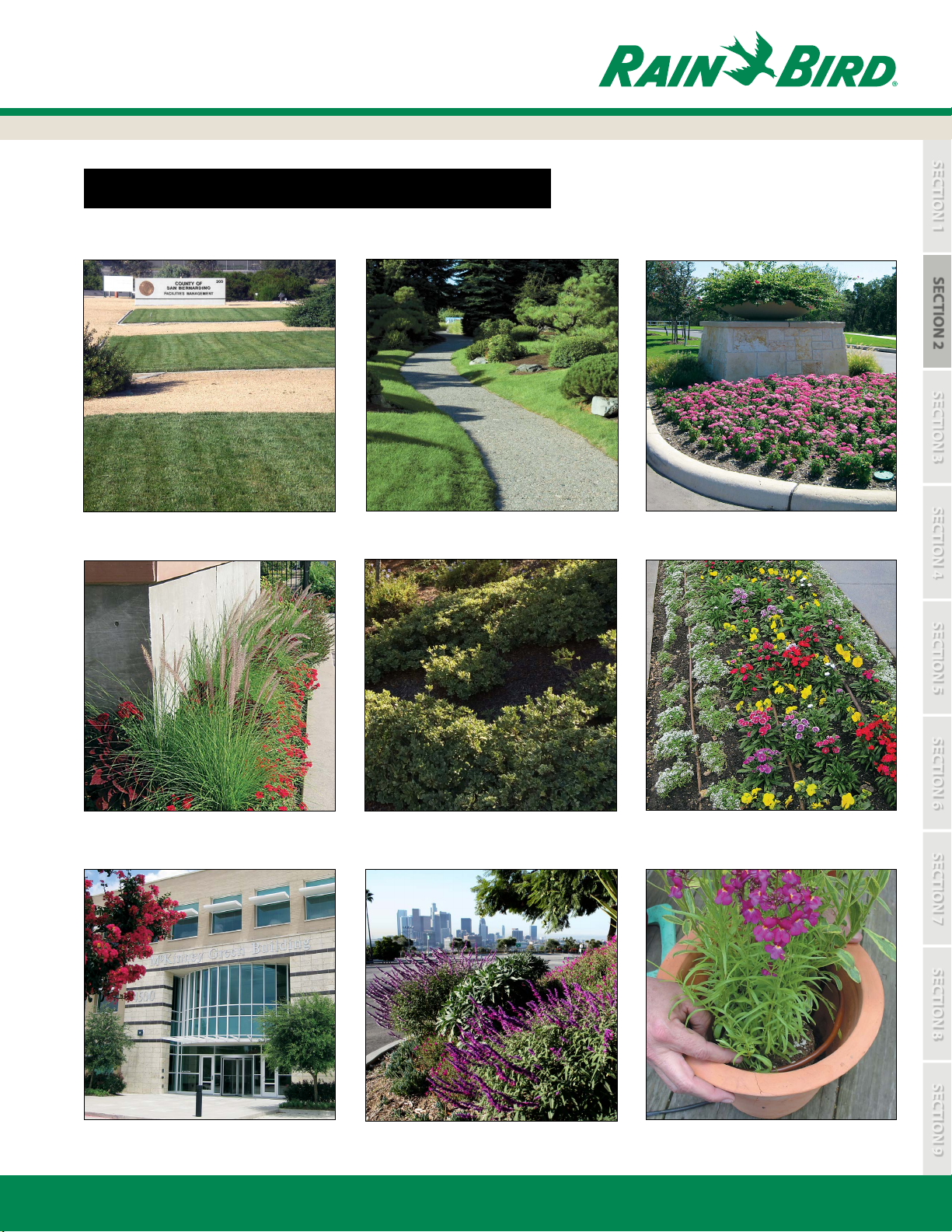
XF SERIES DRIPLINE | WHERE IS IT USED?
SECTION 2
Small Conned Areas
Flower BedsCurved LandscapesTurf Grass (XFS, XFS-CV)
Narrow LandscapesShrub & Ground Cover Beds
Eliminate Overspray on Buildings Sloped Areas
www.rainbird.com
Potted Plants (¼” Dripline
9
Page 10
SECTION 1
SECTION 4
SECTION 7
SECTION 5
SECTION 8
SECTION 3
SECTION 6
SECTION 9
SECTION 2:
Preparation for Design
PREPERATION FOR DESIGN
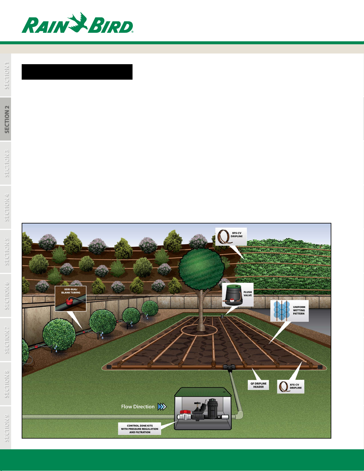
Dripline system design follows many of the same rules as spray and rotor design. Similar design factors must be considered, such
as point of connection, static and operating pressures, ow rates, and plant material.
A dripline system when properly designed and installed will deliver full irrigation coverage to the planted area. A dripline system
is normally divided into zones. A typical zone contains a water source, a control zone (valve, lter, and pressure regulator), and the
dripline with connection ttings.
SECTION 2
During the preparation for design you will gather essential information to design the dripline system:
• Obtain or draw a scaled plan of the site to be irrigated
• Identify all of the slopes on the plan
• Determine the types of plants to be irrigated
(groundcover, shrubs, turfgrass, and trees)
• Identify the type of soil (Clay, Loam, Sand)
• Identify the type of water from the water source
(potable, non-potable, well, surface water, etc)
• Identify static and operating pressures, and volume
available from the water source
• Select appropriate system components for installation
EXAMPLE OF A SUBSURFACE DRIPLINE SYSTEM LAYOUT
10
www.rainbird.com
Page 11
SECTION 1
SECTION 4
SECTION 7
SECTION 5
SECTION 8
SECTION 3
SECTION 6
SECTION 9
SECTION 2:
Preparation for Design
DETERMINE SOIL TYPE | WHAT IS YOUR SOIL TYPE?
OVERALL DESIGN PLAN FOR THE SITE
Soil Inltration Rates (in Inches per Hour)
Percent of Slope
0% - 4% 0.13 - 0.44 0.44 - 0.88 0.88 - 1.25
5% - 8 %
Soil Inltration Rates (in cm per Hour)
Percent of Slope
0% - 4% 0.33 -1.12 1.12 - 2.24 2.24 - 3.18
5% - 8 %
Note: As the slope increases, inltration rates will continue to decrease.
These values are derived from USDA information.
Clay Loam Sand
0.1 - 0.35 0.35 - 0.7 0.7 - 1
Clay Loam Sand
0.25 - 0.89 0.89 - 1.78 1.78 - 2.54
SECTION 2
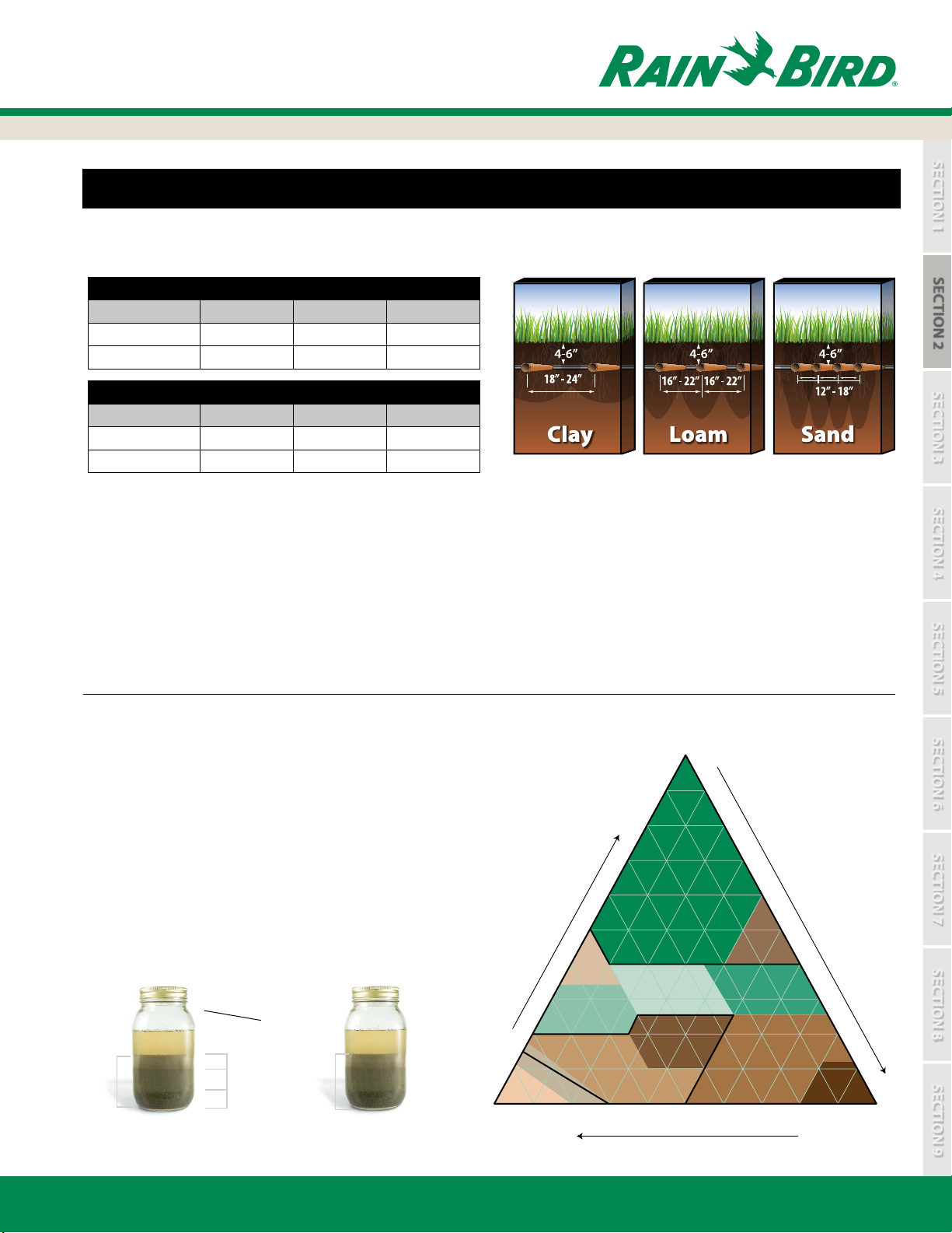
These illustrations show water movement in a subsurface application.
These guidelines apply to on-surface as well as subsurface installations.
The objective of a well-designed dripline system is to create an even wetting pattern of water in the soil throughout
the planting zone. There are four factors to consider for planting areas to create an even wetting pattern:
• Soil type (Clay, Loam, Sand)
• Emitter ow rate: 0.4 GPH, 0.6 GPH or 0.9 GPH (1.6 L/HR, 2.3 L/HR or 3.4 L/HR)
• Emitter spacing: 12” or 18” (0.30 m or 0.45 m)
• Lateral spacing (distance between the dripline rows)
SOIL TYPE TEST
1. Remove 1 to 2 cups of soil from the zone to be irrigated.
2. Place into a glass jar, like a mason jar.
3. Fill the jar half way with water. Shake and let sit for
2 hours so the particles can settle. The heavier sand particles
will settle to the bottom, then silt, then clay on top.
4. Measure the combined height of all three layers of the soil
then the height of each layer; divide the height of each layer
by the total height to gure out the percentage of each soil in
80 20
70 30
60
the jar.
5. Apply these gures to the “Soil Classication” chart.
In the example, now you know the landscape soil is silt loam.
Measure total height and layer heights
Layer Height
Total Height
= Soil Percentage
Total Height
Clay Height
Silt Height
Sand Height
For Example:
3” Total Height
17% 1/2” Clay
66% 2” Silt
17% 1/2” Sand
20
10
Sand
100 90 80 70 60 50 40 30
rcentage of Clay
Pe
40
30
Sandy Clay
Sandy Loam
Loamy
Sand
50
Sandy
Clay
Loam
100
90 10
Clay
Clay Loam
Loam
Percentage of Sand
40
50
Silty
Clay
Silty Clay
Loam
Silt Loam
Pe
rcentage of Silt
60
70
80
90
Silt
20 10 0
100
www.rainbird.com
11
Page 12
SECTION 1
SECTION 4
SECTION 7
SECTION 2
SECTION 5
SECTION 8
SECTION 6
SECTION 9
SECTION 3: Determine Dripline Specications
SECTION 3
SECTION 3:
Determine Dripline Specications
12
www.rainbird.com
Page 13
SECTION 1
SECTION 4
SECTION 7
SECTION 2
SECTION 5
SECTION 8
SECTION 6
SECTION 9
SECTION 3:
Determine Dripline Specications
SECTION 3: DETERMINE DRIPLINE SPECIFICATIONS
CHOOSE THE EMITTER FLOW RATE, SPACING BETWEEN EMITTERS, AND
SPACING BETWEEN ROWS
To determine the specication for the emitter ow rate and emitter spacing for the XF Series Dripline, follow the column
under the proper soil type for your application to nd the emitter ow and emitter spacing.
Table 2 gives recommended emitter ow rates and spacing for three basic soil types. If the soil type is not known, or if there is
a good chance that there will be many dierent types of soil at the site, use the shortest distance between emitters and rows
from the table to be sure that the root zone is well irrigated. If there is heavy loam or clay subsoil, these soil types will reduce
the downward ow of water in the soil and allow for wider lateral spacing between rows.
SECTION 3
TABLE 2: XF SERIES DRIPLINE RECOMMENDATION TABLES
XF Series Dripline Recommendations (English)
Soil Type Clay Loam Sand
Emitter Flow Rate (gallons per hour) 0.4 GPH
Emitter Spacing (inches)
Dripline Lateral Spacing (inches)
XF Series Dripline Recommendations (Metric)
Soil Type Clay Loam Sand
Emitter Flow Rate (liters per hour) 1.6 L/HR
Emitter Spacing (meters)
Dripline Lateral Spacing (meters)
Note: These are general guidelines, eld conditions may require modication to emitter ow rate, emitter spacing and lateral spacing. XF Series Dripline is to be installed at a depth of 4”-6”
(10.2-15.24 cm) in subsurface and groundcover applications. Use only XFS or XFS-CV dripline in subsurface applications. XF Series Dripline may also be installed on-surface under mulch in
shrub and groundcover applications.
If you are not quite sure of the soil type, here is a test you can use by squeezing the soil in your hand:
18” 18” 12”
18” - 24” 16 - 22” 12” - 18”
0.45 0.45 0.3
0.45 - 0.61 0.41 - 0.56 0.3 - 0.45
0.6 GPH 0.9 GPH
2.3
L/HR
3.4
L/HR
Clay - When dry it forms hard clumps. When damp it is exible and can be molded into shapes.
Loam - A moderate sand or dirt and very little clay. When dry it breaks easily. When wet it forms a lump.
Sand - Soil particles are loose, sandy grains. When dry it will fall apart when you open your hand. When damp it will form a lump
but it will crumble easily when touched.
www.rainbird.com
13
Page 14
SECTION 1
SECTION 7
SECTION 2
SECTION 5
SECTION 8
SECTION 3
SECTION 6
SECTION 9
SECTION 4: Determine Type of Dripline Layout
SECTION 4:
Determine Type of Dripline Layout
SECTION 4
14
www.rainbird.com
Page 15
SECTION 1
SECTION 7
SECTION 2
SECTION 5
SECTION 8
SECTION 3
SECTION 6
SECTION 9
SECTION 4:
Determine Type of Dripline Layout
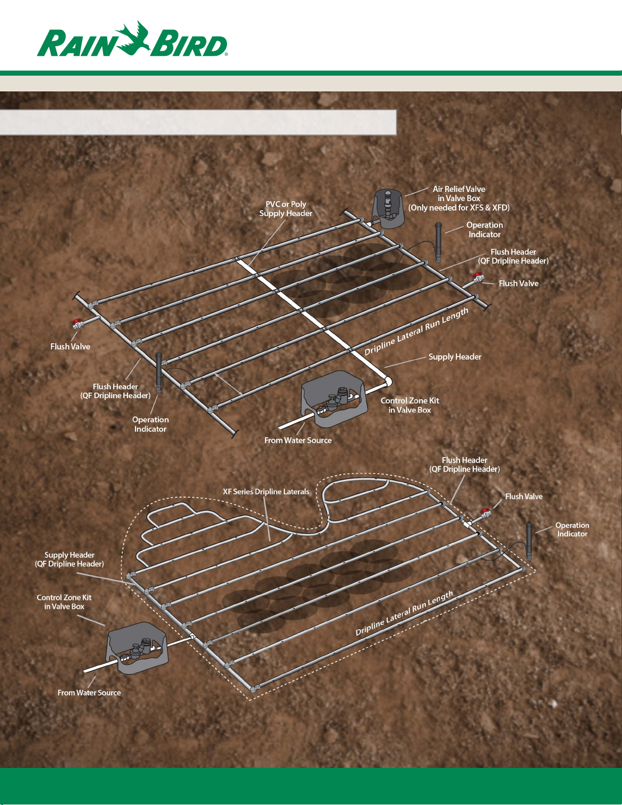
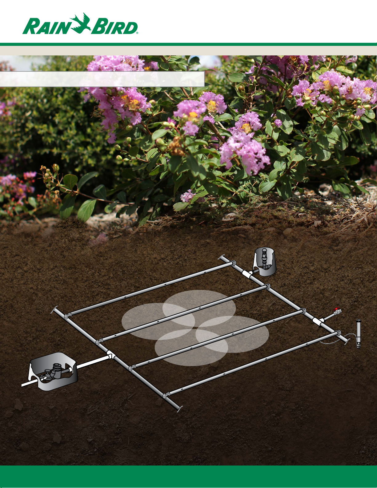
SECTION 4: DETERMINE TYPE OF DRIPLINE LAYOUT | SUBSURFACE
END FEED LAYOUT
This Grid layout is primarily used for dense plantings. The layout uses supply headers and ush headers with rows of dripline
connected at each end. The supply header and ush header form a continuous loop where all rows of dripline are being
supplied from both ends.
Inline Emitters
Control Zone Kit
in Valve Box
XF Series Dripline
Laterals
Wetted Area
Air Relief Valve
in Valve Box
(Only needed
for XFS & XFD)
Flush Header
(QF Dripline Header)
Lateral lines
Flush Valve
Operation
Indicator
SECTION 4
From Water Source
Lateral spacing
QF Dripline Header, PVC
or polyethylene tubing
Dripline Lateral Run Length
CENTER FEED LAYOUT
Where layout exibility exists, it is recommended that Center Feed layouts be used. This allows for the most even ow of
water through the zone. Center Feed layouts also potentially allow you to increase the size of the zone by providing lateral
runs on both sides of the supply header. Center Feed layouts are an excellent option for median strips, road sides, and other
homogenous planting zones.
Air Relief Valve
in Valve Box
(Only needed for XFS & XFD)
Operation
Indicator
Flush Header
(QF Dripline Header)
Flush Valve
Supply Header
Flush Valve
PVC or Poly
Supply Header
Dripline Lateral Run Length
Flush Header
(QF Dripline Header)
Operation
Indicator
www.rainbird.com
Lateral spacing
From Water Source
Control Zone Kit
in Valve Box
15
Page 16
SECTION 1
SECTION 7
SECTION 2
SECTION 5
SECTION 8
SECTION 3
SECTION 6
SECTION 9
SECTION 4:
Determine Type of Dripline Layout
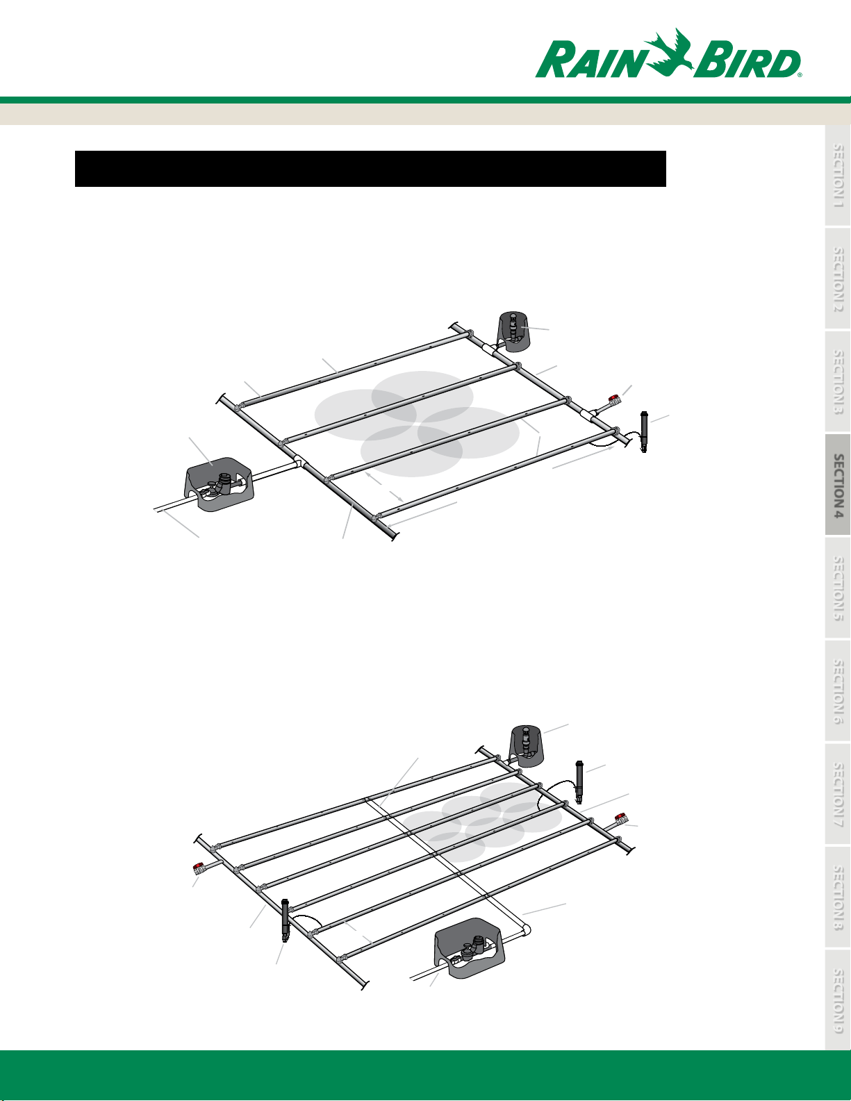
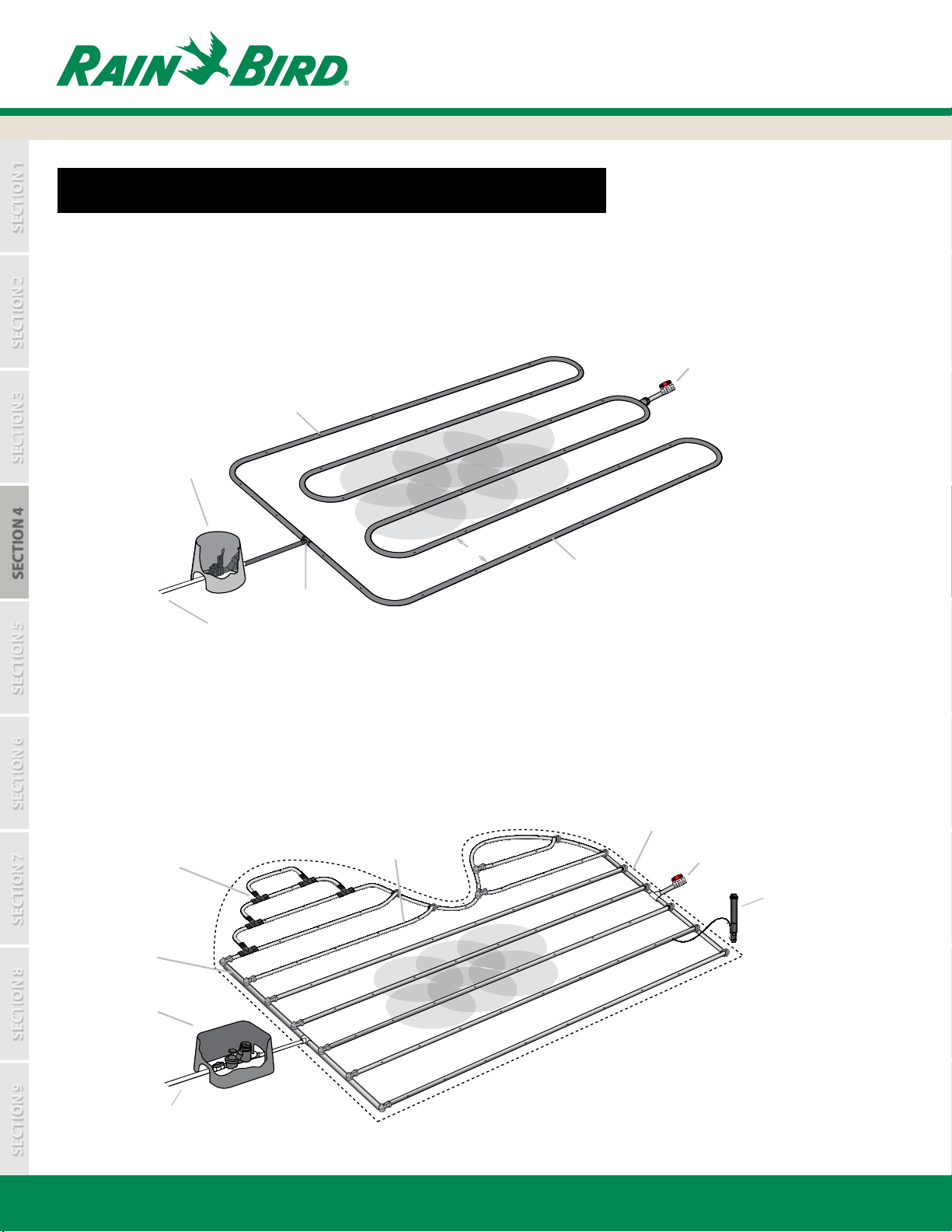
DETERMINE TYPE OF DRIPLINE LAYOUT | ON-SURFACE
QUICK LOOP LAYOUT
The Loop layout is one continuous loop that weaves back and forth throughout the zone in evenly spaced laterals (rows).
Flush Valve
Inline Emitters
Control Zone Kit
in Valve Box
Lateral spacing
SECTION 4
Insert or
Compression
From Water Source
Fitting
Wetted
Area
XF Series Dripline
CURVED EDGE LAYOUT
The Curved Edge layout is primarily used for dense planting areas. The layout uses supply and ush headers with rows of
dripline connected at the end. The supply and ush header form a continuous loop and the dripline can be attached to
the adjacent driplines with “tee” ttings to accommodate curved applications.
Flush Header
(QF Dripline Header)
Insert or
compression tting
XF Series Dripline Laterals
Flush Valve
Operation
Indicator
Supply Header
(QF Dripline Header)
Control Zone Kit
in Valve Box
Dripline Lateral Run Length
PVC or Poly
Supply Header
From Water Source
16
Control Zone
www.rainbird.com
Page 17
SECTION 1
SECTION 7
SECTION 2
SECTION 5
SECTION 8
SECTION 3
SECTION 6
SECTION 9
T
Check longest lateral
against Table 2 for
maximum lateral
length.
Supply Header
Exhaust Header
SECTION 4:
Determine Type of Dripline Layout
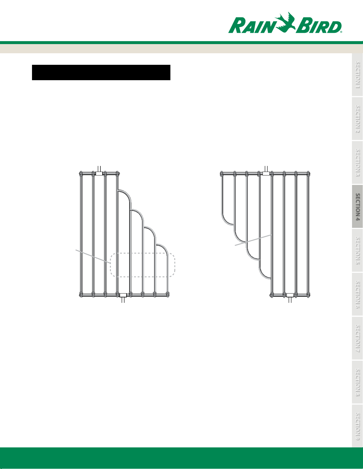
OTHER COMMON GRID LAYOUTS
BRANCHING OUT OR JOINING LAYOUTS
When branching out from a supply header with XF Series dripline, maximum lateral run length should be considered.
Add up all the “branched out” dripline and check it against the maximum lateral run lengths listed in Tables 6, 7, 8, or 9.
This will vary depending on the type of tubing being used.
When joining lateral rows from a supply header, check only the longest lateral against the maximum lateral run length
listed in Tables 6, 7, 8, or 9.
Branching Out
with XF Series
Laterals
otal the combined
length of these XF Series
Dripline laterals and
compare it against the
maximum lateral length
allowed in Table 6.
Supply Header
(QF Dripline Header)
Flush Header
(QF Dripline Header)
Joining Rows
with XF Series
Laterals
Check longest lateral
against Tables 6,7,or 8
for maximum lateral
length.
Supply Header
(QF Dripline Header)
SECTION 4
Flush Header
DESIGN CONSIDERATIONS
• Header should be spaced 2” - 4” (5cm-10.2 cm) from hardscape or other planting areas
• Headers may be QF Header, PVC, blank poly tubing or dripline
• Lateral spacing is a design consideration and can be calculated as shown on page 19 in “How to Calculate
Equal Lateral (Row) Spacing”
• The lateral run length should not exceed the maximum lateral run length shown in Tables 6, 7, 8, or 9
• When using “Center Feed Layout” the run length should be measured from the supply header to the ush
header and should not exceed the maximum run length shown
• When using “Loop Layout”, because water is split into two separate paths that meet in the middle, the total
continuous loop length of dripline should not exceed twice the maximum lateral length
• In subsurface applications an air vacuum relief valve should be installed at the highest point in the system
to avoid back siphoning debris into the emitter
• Flush valves should be installed at the low point in the ush header or at the mid point of the loop layout
www.rainbird.com
17
Page 18
SECTION 1
SECTION 7
SECTION 2
SECTION 5
SECTION 8
SECTION 3
SECTION 6
SECTION 9
10 FT. SLOPE
ZONE 1
CONTROL ZONE 1
Top of Slope
Toe of Slope
SECTION 4:
Determine Type of Dripline Layout
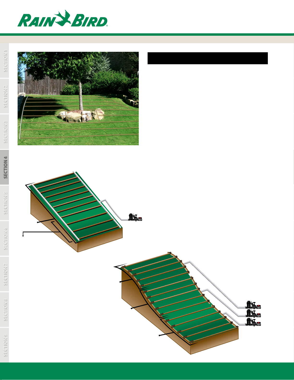
SLOPES
• The design of the dripline system should account for
slopes on the site since runo may occur at low points
• Slopes less than 3% do not require special design
considerations
• Slopes greater than 3% should increase the dripline
spacing by 25% in the bottom 1/3 of the zone
• Dripline should run perpendiculur (across) the slope when
possible
ELEVATION CHANGES SLOPE LAYOUT
SECTION 4
*Increase the dripline
row spacing by 25%
in the bottom 1/3 of
the zone
SLOPES GREATER THAN 10 FT
USING XFSCV DRIPLINE:
• With steep sloping landscapes
greater than 10 ft., it is recommended
that additional zones are installed to
reduce runo
• The use of XFS-CV can eliminate low
emitter drainage
ZONE 1
ZONE 2
SLOPES UP TO 10 FT. USING XFSCV DRIPLINE:
• With sloping landscapes up to 10 ft. of elevation
change, no seperate zones or check valves are required
Top of Slope
30 FT. SLOPE
CONTROL ZONE 1
CONTROL ZONE 2
CONTROL ZONE 3
ZONE 3
18
Toe of Slope
www.rainbird.com
Page 19
SECTION 1
SECTION 7
SECTION 2
SECTION 5
SECTION 8
SECTION 3
SECTION 6
SECTION 9
SECTION 4:
Determine Type of Dripline Layout
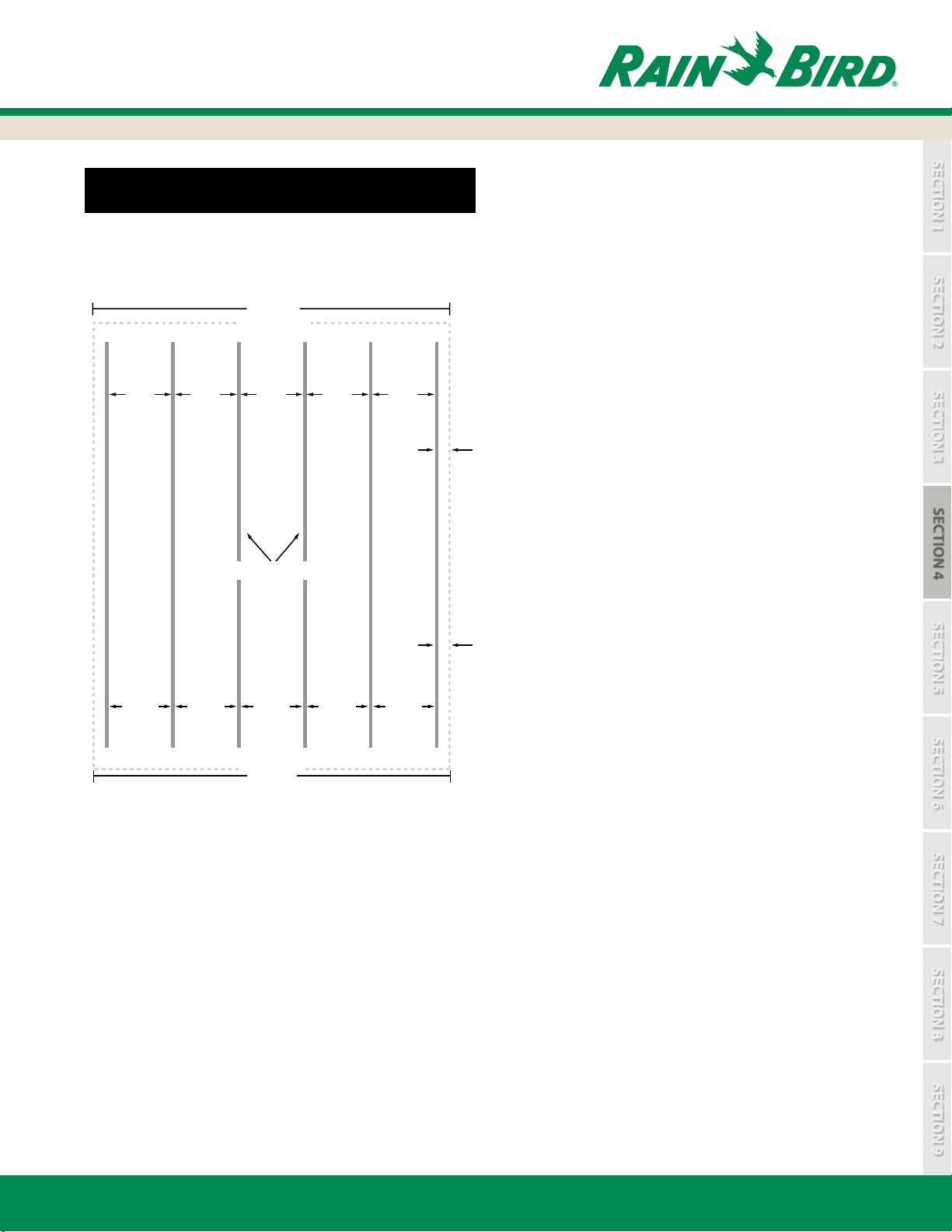
DETERMINE LATERAL ROW SPACING
Application Width
8 feet
(96 inches)
18.4”
45cm
18.4” 18.4” 18.4” 18.4”
XF Series Dripline
45cm
45cm
2.4 m
(243 cm)
45cm
2”–4”
from
hardscape
5 cm–10.2 cm
from
hardscape
45cm
HOW TO CALCULATE EQUAL
LATERAL ROW SPACING WHEN
MAKING CUSTOM PVC HEADERS
Loam soil is assumed for the example below with a
recommended lateral row spacing of 16”-22” as shown in
Table 2 on Page 13. To calculate the specic lateral row
spacing within this range, you need to know the width of the
zone being irrigated and then use the calculation as show in
Example 1.
Example 1: How to Calculate Equal Lateral (Row) Spacing
• Application width = 8’ (2.4 m)
• Convert into inches: 8’ x 12” = 96”
or (Convert into centimeters: 2.43 m x 100 = 243 cm)
• It is recommended to space dripline 2” (5 cm) from
hardscapes and 4” (10.2 cm) from separate planting zones
In this example there are hardscapes on each side of the
planting zone. Remove the hardscape spacing on each
side from the total width:
96” - (2x2”) = 92” (243 cm - (2x5 cm) = 233 cm)
• For loam soil, the range of lateral row spacing is 16”-22”
(40.6 cm - 55.9 cm). Choosing 18”, calculate the number of
spaces between rows: 92” ÷ 18” = 5.1 (233 cm ÷ 0.45 m =
5.1). Round to get whole spaces. Round up if the decimal
is 0.5 or higher, round down if it is less than 0.5. In this case
you should round down to 5 whole spaces between rows.
SECTION 4
• Calculate the equal lateral row spacing: 92” ÷ 5 = 18.4” (233
cm ÷ 5 = 45 cm)
• Calculate the number of dripline rows by adding 1 to the
number of spaces between rows: 5 + 1 = 6 dripline rows
www.rainbird.com
19
Page 20
SECTION 1
SECTION 4
SECTION 7
SECTION 2
SECTION 8
SECTION 3
SECTION 6
SECTION 9
SECTION 5: Zone Water Calculations
SECTION 5:
Zone Water Calculations
SECTION 5
20
www.rainbird.com
Page 21

SECTION 1
SECTION 4
SECTION 7
SECTION 2
SECTION 8
SECTION 3
SECTION 6
SECTION 9
SECTION 5:
Zone Water Calculations
TABLE 3: CALCULATING ZONE WATER REQUIREMENTS
XF Series Dripline Flow (per 100 feet)
Emitter Spacing 0.4 GPH Emitter 0.6 GPH Emitter 0.9 GPH Emitter
Inches GPH GPM GPH GPM GPH GPM
12” 42 0.70 61 1.02 92 1.53
18” 28 0.47 41 0.68 61 1.02
Control Zone
in Valve Box
Inline Emitters
XF Series Dripline
Laterals
Wetted Area
Air Relief Valve
in Valve Box
(Only needed
for XFS & XFD)
Flush Header
(QF Dripline)
Flush Valve
XF Series Dripline Flow (per 100 Meters)
Emitter Spacing 1.6 L/HR
Emitter
2.3 L/HR
Emitter
3.4 L/HR
Emitter
Centimeters L/HR L/MIN L/HR L/MIN L/HR L/MIN
From Water Source
PVC, polyethylene
tubing, or QF Dripline
header
Lateral spacing
Dripline Lateral Run Length
30cm 533 8.89 767 12.78 1133 18.89
46cm 348 5.80 500 8.33 739 12.32
Note: This example represents approximately 650’ of dripline.
After the dripline layout design is complete, you will need to identify total zone ow. This is used to help select mainline, supply and
ush headers, and control zone kit (valve, lter, and regulator).
1. Calculating zone water requirements can be done by adding up the total length of dripline in the zone. Convert the total
dripline length to hundreds of feet (meters). 650 feet (198 m) would be 6.5 in hundreds of feet (1.98 m).
2. Multiply total dripline length in hundreds of feet (meters) by the ow per 100 feet (meters) for your specied dripline. This can
be found in Table 3. To read the table, select the emitter ow rate in the row across the top (0.4 GPH (1.6 L/HR), 0.6 GPH (2.3 L/
HR), or 0.9 GPH (3.4 L/HR) and then select the emitter spacing in the left column (12” (0.30 m) or 18” (0.46 m). Follow emitter
ow rate down and emitter spacing across to nd the ow per 100 feet (meters) for the XF Series dripline specied.
3. For example, for a zone that has 650 feet (198 m) of 0.9 GPH (3.4 L/HR) emitters and 18” (0.46 m) emitter spacing, the calculation
would be 6.50 x 1.02 GPM = 6.6 GPM (1.98 m x 12.32 L/MIN = 24.4 L/MIN) for the zone.
4. Supply lines and headers should be sized to provide the ow to the zone without exceeding 5 feet (meters) per second velocity.
This can be done using the zone water requirement and referencing information on the appropriate piping located at
www.rainbird.com/reference or in the back reference section in the Rain Bird catalog.
SECTION 5
TABLE 4: DETERMINE MAXIMUM FLOW PER ZONE
Maximum Flow Per Zone (English)
Sch.
40 PVC
or QF
Header
Size
Max.
Flow*
GPM
psi
Loss**
Poly
Pipe
Header
Size
Max.
Flow*
GPM
psi
Loss**
½” 4.7 GPM 7.7 psi ½” 4.7 GPM 8.8 psi
¾” 8.3 GPM 5.6 psi ¾” 8.3 GPM 6.3 psi
1” 13.5 GPM 4.2 psi 1” 13.5 GPM 4.8 psi
1-¼” 23.1 GPM 3.1 psi 1-¼” 23.1 GPM 3.1 psi
1-½” 33.9 GPM 2.9 psi 1-½” 33.9 GPM 2.9 psi
2” 52.4 GPM 1.9 psi 2” 52.4 GPM 1.9 psi
* Based on maximum velocity of 5’ per second
** Per 100’ of tubing
Sch.
40 PVC
or QF
Header
Size
1.27 cm 17.8 0.53 1.27 cm 17.8 0.61
1.91 cm 31.4 0.39 1.91 cm 31.4 0.43
2.54 cm 51.1 0.29 2.54 cm 51.1 0.33
3.18 cm 87.4 0.21 3.18 cm 87.4 0.22
3.81 cm 128.3 0.20 3.81 cm 128.3 0.20
5.08 cm 198.4 0.13 5.08 cm 198.4 0.13
* Based on maximum velocity of 1.52 m per second
** Per 30.5 meters of tubing
www.rainbird.com
Maximum Flow Per Zone (Metric)
Max.
Flow*
L/MIN
psi
Loss**
Poly
Pipe
Header
Size
Max.
Flow*
L/MIN
psi
Loss**
21
Page 22

SECTION 1
SECTION 4
SECTION 7
SECTION 2
SECTION 8
SECTION 3
SECTION 6
SECTION 9
SECTION 5:
Zone Water Calculations
CALCULATING APPLICATION RATES
APPLICATION RATE
The application rate is the rate that XF Series Dripline applies water to the soil. This is used to determine run times for the zone
based on the plant watering requirements. Table 5 is provided to make it easy to determine application rates for every model of
XF Series Dripline when using common row spacing (12”-24” / 30cm-61cm). The table is divided into three sections, a 0.4 GPH
(1.6 L/HR) emitter ow section, a 0.6 GPH (2.3 L/HR) emitter ow section and a 0.9 GPH (3.4 L/HR) emitter ow section. Go to the
section for the specied emitter ow rate and nd in the left hand column the specied emitter spacing. Next, nd the lateral row
spacing across the top of the table. Follow the lateral row spacing column down and the emitter spacing row across until the two
meet. This is the application rate in inches per hour (centimeters per hour). For example, a 0.6 GPH (2.3 L/HR) emitter ow rate
with 18” (46 cm) lateral row spacing and 18” (46 cm) emitter spacing has an application rate of 0.43 (1.09 cm/hr) inches per hour.
TABLE 5: APPLICATION RATE
Emitter
Spacing
SECTION 5
Emitter
Spacing
30cm 1.78 1.62 1.48 1.40 1.30 1.24 1.16 1.11 1.05 0.95 0.87
46cm 1.16 1.05 0.97 0.92 0.85 0.81 0.76 0.72 0.68 0.62 0.57
30cm 2.44 2.26 2.11 1.96 1.86 1.73 1.63 1.55 1.47 1.35 1.22
46cm 1.63 1.50 1.40 1.30 1.22 1.14 1.09 1.02 0.99 0.89 0.81
30cm 3.66 3.38 3.15 2.95 2.74 2.59 2.44 2.31 2.21 2.01 1.83
46cm 2.44 2.26 2.11 1.96 1.83 1.73 1.63 1.55 1.47 1.35 1.22
Lateral Row Spacing (in Inches)
12” 13” 14” 15” 16” 17” 18” 19” 20” 22” 24”
0.4 GPH Emitter Flow (Inches per hour)
12” 0.67 0.62 0.58 0.54 0.51 0.48 0.45 0.43 0.40 0.37 0.34
18” 0.45 0.41 0.39 0.36 0.34 0.32 0.30 0.28 0.27 0.25 0.22
0.6 GPH Emitter Flow (Inches per hour)
12” 0.96 0.89 0.83 0.77 0.72 0.68 0.64 0.61 0.58 0.53 0.48
18” 0.64 0.59 0.55 0.51 0.48 0.45 0.43 0.41 0.39 0.35 0.32
0.9 GPH Emitter Flow (Inches per hour)
12” 1.44 1.33 1.24 1.16 1.08 1.02 0.96 0.91 0.87 0.79 0.72
18” 0.96 0.89 0.83 0.77 0.72 0.68 0.64 0.61 0.58 0.53 0.48
Lateral Row Spacing (in Centimeters)
30 33 36 38 41 43 46 48 51 56 61
1.6 LPH Emitter Flow (cm per hour)
2.3 LPH Emitter Flow (cm per hour)
3.4 LPH Emitter Flow (cm per hour)
At this point the emitter ow rate and spacing between emitters and rows has been selected.
Use the tables to determine the overall water application rate for the landscape area.
22
www.rainbird.com
Page 23

SECTION 1
SECTION 4
SECTION 7
SECTION 2
SECTION 8
SECTION 3
SECTION 6
SECTION 9
SECTION 5:
Zone Water Calculations
CALCULATIONS FOR DRIPLINE IRRIGATION
HOW DO I DETERMINE THE APPLICATION RATE?
_______________________________________________
Lateral Row Spacing in Inches x Emitter Spacing in Inches
Example:
Emitter Flow Rate 0.6 GPH
Emitter Spacing 12 inches
Lateral Row Spacing 18 inches
0.6 x 231.1
_________
12 x 18
Emitter Flow Rate in GPH x 231.1
= 0.64 inches/hour
__________________________________________
Lateral Row Spacing in cm x Emitter Spacing in cm
Example:
Emitter Flow Rate 2.3 L/HR
Emitter Spacing 30 cm
Lateral Row Spacing 41 cm
2.3 x 1,000
_________
30 x 41
Emitter Flow Rate in L/HR x 1000
= 1.86 cm/hr
WHAT IS THE TOTAL FLOW WITHIN THE DRIP ZONE?
Irrigated Area in Sq Ft. x Emitter Flow in GPH x 2.4
_______________________________________________
Lateral Row Spacing in Inches x Emitter Spacing in Inches
Example:
Irrigated Area 2500 Sq Ft
Emitter Flow Rate 0.6 GPH
Emitter Spacing 18 inches
Lateral Row Spacing 18 inches
2500 x 0.6 x 2.4
_____________
18 x 18
= 11.11 GPM
Irrigated Area in Sq Meters x Emitter Flow in L/HR x 166.7
______________________________________________
Lateral Row Spacing in cm x Emitter Spacing in cm
Example:
Irrigated Area 800 Sq Meters
Emitter Flow Rate 3.4 L/HR
Emitter Spacing 46 cm
Lateral Row Spacing 48 cm
800 x 3.41 x 166.7
__________________
46 x 48
METRIC
SECTION 5
= 206 L/MIN
HOW MUCH DRIPLINE DO I NEED BASED ON SIZE OF IRRIGATED AREA?
Area in Sq Ft. x 12
_________________________
Lateral Row Spacing in Inches
Example:
Irrigated Area 2165 Sq Ft
Lateral Row Spacing 18 inches
2165 x 12
________
18
= 1443 feet of dripline needed
Example:
Irrigated Area 425 Sq Meters
Lateral Row Spacing 36 cm
425 x 100
________
36
= 1180 meters of dripline needed
Area in Sq. Meters x 100
__________________________
Lateral Row Spacing in cm
HOW MANY FEET OF DRIPLINE CAN I USE IF I KNOW THE AVAILABLE FLOW
Available Flow
_____________________
Flow per 100 Foot Length
Obtain “Flow per 100 Feet”
Example:
You have 11 GPM available ow
0.6 GPH emitters on 18” spacing - See table 3
11 GPM
________
0.68 GPM
x 100 feet = 1618 maximum feet of dripline
x 100 = Maximum Feet
_________________________
Obtain “Flow per 100 Meters”
Example:
You have 130 L/MIN available ow
2.3 L/HR emitters on 0.46 meter spacing - See table 3
130 L/MIN
________
2.31 L/HR
Available Flow
Flow per 100 Meter Length
x 100 meters = 5628 maximum feet of dripline
x 100 = Maximum Meters
www.rainbird.com
23
Page 24

SECTION 1
SECTION 4
SECTION 7
SECTION 2
SECTION 8
SECTION 3
SECTION 6
SECTION 9
Zone Water Calculations
IRRIGATION FORMULAS
PLANT WATER REQUIREMENT FOR A DENSE PLANTING SCHEME
The water requirement for a densely planted hydro-zone is measured in inches per day.
SECTION 5:
Plant Water Requirement = PET x K
Potential Evapotranspiration (PET) - The amount of water that us used by the combination of evaporation from
the soil and transpiration from plants growing in the soil. PET is generally expressed in inches per day.
Kc - Adjustment factor to PET that accounts for the needs of a specic plant in growing conditions. It is also known
as the “crop coecient” or the “plant factor.”
Example: The PET for a day in the summer for Las Vegas is: 0.30” (0.76 cm)
The Kc or “plant factor” for a certain type of plant and it’s surroundings is 0.84 (2.13 cm)
Plant Water Requirement = 0.30” x 0.84 = 0.25”/day (0.76 cm x 2.13 cm = 1.62 cm per day)
SYSTEM RUN TIME
SECTION 5
The formula for system run time for dense plants is based on a measurement of ow in inches per day.
System Run Time = (PWR / Application Rate x Application Eciency) x 60
c
Example: (0.25” / 0.64” x 0.90) x 60 = 26 minutes
(0.63 cm/1.62 x 0.90) x 60 = 26 minutes
Example:
Plant Water Requirement: 0.25”/day (0.63 cm/day)
Application Rate: 0.64” (1.62 cm)
Drip Application Eciency: 90%
System Run Time = (0.25/0.64 x 0.90) x 60 = 26 minutes (0.63 cm/1.62 x 0.90) x 60 = 26 minutes
More detailed information on calculating Plant Water Requirement and System Run Time can be found in the Low-Volume Landscape Irrigation
Design Manual; Chapters 4 & 5. This manual is only available for download on our website:
https://www.rainbird.com/sites/default/les/media/documents/2018-02/LowVolumeGuide.pdf
24
www.rainbird.com
Page 25

SECTION 1
SECTION 4
SECTION 7
SECTION 2
SECTION 5
SECTION 8
SECTION 3
SECTION 9
SECTION 6:
DRIPLINE
PRODUCT
XFSCV
DRIPLINE
XFCV
DRIPLINE
XFS
DRIPLINE
XFD
DRIPLINE
1/4”
DRIPLINE
LANDSCAPE
CHALLENGES
ON-SURFACE AND
SUBSURFACE
Sloped and
Level Grade
ON-SURFACE
Sloped and
Level Grade
SUBSURFACE
Level Grade
ON-SURFACE
Level Grade
Installations
ON-SURFACE
Potted/Small Bed
Installations
SUB SURFACE
APPLICATIONS
X X
SLOPED AREAS
X X
SHRUB & GROUND
COVER BEDS
X X X X X
CONTAINER PLANTS
X X X X X
CURVED LANDSCAPES
X X X X X
NARROW LANDSCAPED
AREAS
X X X X X
MEDIANS OR
PARKING ISLANDS
X X X X
TURF GRASS
X X
DRIPLINE
FEATURES
XFS-CV
DRIPLINE
• Heavy-Duty 4.3 psi
Check Valve provides
10 ft. of holdback
• Copper Shield™
emitter root intrusion
• Longer lateral runs
• Exceptional durability
• Available in purple
and purple stripe for
non-potable water
XFCV
DRIPLINE
• 3.5 psi Check Valve
provides 8 ft. of
holdback
• Longer lateral runs
• Exceptional durability
XFS
DRIPLINE
• Copper Shield™
emitter root intrusion
• Exceptional durability
• Available in purple
and purple stripe for
non-potable water
XFD
DRIPLINE
• Greater exibility
• Longer lateral runs
• Exceptional durability
• Available in purple
and purple stripe for
non-potable water
1/4”
DRIPLINE
• In-line non-pressure
compensated emitters
• Perfect for pots and
small beds
• Easy installation
Dripline Models for Every Application
SECTION 6: Dripline Models for Every Application
SECTION 6
www.rainbird.com
25
25
Page 26

SECTION 1
SECTION 4
SECTION 7
SECTION 2
SECTION 5
SECTION 8
SECTION 3
SECTION 9
On/Sub Surface
Sloped Applications
SECTION 6:
Dripline Models for Every Application
XFS-CV DRIPLINE FOR ON/SUB SURFACE ELEVATED APPLICATIONS
ELEVATED PERFORMANCE
With a patented check valve in every emitter that
holds back 10’ of elevation change, XFS-CV dripline
eliminates low-point drainage and provides uniform
irrigation throughout the zone.
COPPER SHIELD™ TECHNOLOGY
Only XFS-CV dripline
includes a pure
copper chip in every
emitter to protect
against root intrusion.
Others use diluted
copper compounds
encapsulated in
plastic.
LOWPROFILE FLAT EMITTER
10 ft. of Holdback
SECTION 6
GREATER FLEXIBILITY
Rain Bird’s low-prole at
emitter design reduces
in-line pressure loss,
allowing longer
lateral runs, simplifying
design and reducing
installation time.
Rain Bird’s proprietary blend
provides industry-leading
exibility allowing for tighter
turns with fewer elbows for fast
and easy installation.
EASY IDENTIFICATION
All dripline models feature
color coded stripes to easily
identify the ow rate:
Black stripes = 0.9 GPH
Tan stripes = 0.6 GPH
LEED COMPLIANT
Contains at least 20% post consumer recycled
polyethylene which qualies for LEED credit 4.2.
26
www.rainbird.com
Page 27

SECTION 1
SECTION 4
SECTION 7
SECTION 2
SECTION 5
SECTION 8
SECTION 3
SECTION 9
SECTION 6:
Dripline Models for Every Application
XFS-CV DRIPLINE - SPECIFICATIONS
Applications
Rain Bird® XFS-CV dripline features Copper
Shield™ Technology and a heavy-duty 4.3 psi
check valve, making it perfect for subsurface
and on-surface applications with level grades
or slopes. A check valve in every emitter
keeps the dripline charged in elevation
changes up to 10 feet, XFS-CV can be used
where no other dripline will work.
Keeping water in the dripline at all times
helps for better irrigation uniformity
throughout the zone. The check valve also
helps prevent puddling and oversaturated
soil at the low point in the zone.
Features
Industry-Leading Protection
• Rain Bird’s XFS-CV dripline with patented
Copper Shield™ Technology protects the
emitter from root intrusion. Unlike other
manufacturers who use harsh chemicals or
diluted copper compounds encapsulated
in plastic, the Copper Shield™ Technology
from Rain Bird provides root intrusion
protection with a pure copper chip at each
emitter
• Rain Bird’s industry leading 4.3 psi emitter
check valve technology keeps the dripline
charged with water when elevation
changes are up to 10 feet, increasing
uniformity of watering and conserving
water by eliminating the need to recharge
the line at the beginning of each irrigation
cycle
Easy to Use
• Through the use of a proprietary tubing
material, the XFS-CV dripline is the most
exible dripline tubing in the industry,
making it the easiest dripline to design
with and install
• It accepts Rain Bird® XF dripline barbed
insert ttings and other 17 mm barbed
insert ttings
• Rain Bird’s low-prole emitter design
reduces in-line pressure loss, allowing
longer lateral runs, simplifying design and
reducing installation time
• A variety of industry standard emitter
ow rates, emitter spacing and coil lengths
provide design exibility for applications
with or without elevation changes
Reliable
• The pressure-compensating emitter design
provides a consistent ow over the entire
lateral length, ensuring higher uniformity
for increased reliability in the pressure
range of 20 to 60 psi
Durable
• Dual-layered tubing (copper over black)
provides unmatched resistance to
chemicals, algae growth and UV damage
Grit Tolerant
• Rain Bird’s proprietary emitter design resists
clogging by use of an extra wide ow path
combined with a self-ushing action
Made with Recycled Content
• All Rain Bird XF Dripline products qualify for
LEED credit 4.2 because they contain at
least 20% polyethylene post-consumer
recycled material by cost
Operating Range
• Opening Pressure: 14.5 psi (1,0 bar)
• Pressure: 20 to 60 psi (1,38 to 4,14 bar)
• Flow Rates: 0.6 and 0.9 GPH (2,3 and 3,5 L/HR)
TABLE 6: LATERAL RUN LENGTHS
XFS-CV Dripline Maximum Lateral Lengths (Feet)
12” Emitter Spacing 18” Emitter Spacing
psi 0.6 GPH 0.9 GPH 0.6 GPH 0.9 GPH
20 192 136 254 215
30 289 205 402 337
40 350 248 498 416
50 397 281 573 477
60* 436 309 637 529
XFS-CV Dripline Maximum Lateral Lengths (Meters)
30,5 cm Emitter Spacing 45,7 cm Emitter Spacing
Bar 2.3 L/HR 3.4 L/HR 2.3 L/HR 3.4 L/HR
1,38 58,5 41,5 77,4 65,5
2,07 88 62,5 122,5 102,7
2,76 107 75,6 151,8 126,8
3,45 121 85,6 174,7 145,4
4,14* 133 94,2 194,2 161,2
* When using 17mm insert ttings with design pressure over 50 psi (3.5 bar), it is recommended that stainless steel clamps be installed on each tting.
• Filtration Requirement: 120 mesh
• Temperature:
– Water: Up to 100° F (37,8° C)
– Ambient: Up to 125° F (51,7° C)
Specications
• OD: 0.634” (16 mm)
• ID: 0.536” (13.61 mm)
• Thickness: 0.049” (1.25 mm)
• Emitter spacing: 12” & 18” (30,5 & 45,7 cm)
• Coil lengths:
100’, 250’, 500’, and 1000’ (special order)
(30,5, 76,5, 152,4, and 304,9 m)
• Coil color: Copper, Purple and Purple Stripe
1,000’ coils available via special order
Models
• XFSCV0612100
• XFSCV0612250
• XFSCV0612500
• XFSCV0618100
• XFSCV0618250
• XFSCV0618500
• XFSCV0912100
• XFSCV0912250
• XFSCV0912500
• XFSCV0918100
• XFSCV0918250
• XFSCV0918500
• XFSCVP612500
• XFSCVP618500
• XFSCVP912500
• XFSCVP918500
• XFSCVPS612500
• XFSCVPS618500
• XFSCVPS912500
• XFSCVPS918500
SECTION 6
www.rainbird.com
27
Page 28

SECTION 1
SECTION 4
SECTION 7
SECTION 2
SECTION 5
SECTION 8
SECTION 3
SECTION 9
On-Surface
Sloped Applications
SECTION 6:
Dripline Models for Every Application
XFCV DRIPLINE FOR ON-SURFACE ELEVATED APPLICATIONS
Elevated Performance
Keeps dripline charged with water even with elevation changes
to 8 feet. The check valve also helps to prevent over-watering
at the low-point in the zone, avoiding puddling from water
draining from the dripline.
SECTION 6
Conserves Water
Prevents puddling and water loss at the low point in the zone.
LEED Compliant
Contains at least 20% post consumer recycled
polyethylene which qualies for LEED credit 4.2.
8 ft. of Holdback
Low-Prole Flat Emitter
Rain Bird’s low-prole at
emitter design reduces in-line
pressure loss, allowing longer
lateral runs, simplifying design
and reducing installation time.
Greater Flexibility
Rain Bird’s proprietary blend
provides industry-leading
exibility allowing for tighter
turns with fewer elbows for
fast and easy installation.
Easy Identication
All dripline models feature
color coded stripes to easily
identify the ow rate:
Black stripes = 0.9 GPH
Tan stripes = 0.6 GPH
28
www.rainbird.com
Page 29

SECTION 1
SECTION 4
SECTION 7
SECTION 2
SECTION 5
SECTION 8
SECTION 3
SECTION 9
SECTION 6:
Dripline Models for Every Application
XFCV DRIPLINE - SPECIFICATIONS
Applications
Rain Bird® XFCV Dripline with a heavy-duty 3.5
psi check valve for on-surface applications is
a valuable addition to the Rain Bird XF Series
dripline family. Rain Bird’s patent-pending
emitter check valve keeps the dripline charged
in elevation changes to 8 feet.
Keeping water in the dripline at all times
improves irrigation uniformity for plants
throughout the zone. The check valve also
helps to prevent over-watering at the lowpoint in the zone, avoiding puddling from
water draining from the dripline.
Features
Simple
• Rain Bird’s patent-pending 3.5 psi check
valve technology keeps the dripline charged
with water at all times, increasing uniformity
of watering, and conserves water by
eliminating the need to recharge the zone
at the beginning of each watering cycle
• Through the use of a proprietary tubing
material, the XFCV Dripline with
heavy-duty check valve is the most exible
dripline tubing in the industry, making it
the easiest dripline to design with and
install
• It accepts Rain Bird Easy Fit Compression
Fittings, XF Dripline Barbed Insert Fittings
and other 17 mm barbed insert ttings
• Rain Bird’s low-prole emitter design
reduces in-line pressure loss, allowing
longer lateral runs, simplifying design and
reducing installation time
• Variety of emitter ow rates, emitter spacing
and coil lengths provide design exibility for
on-surface areas with or without elevation
changes
Made with Recycled Content
• All Rain Bird XF Dripline (XFD, XFS, XFCV,
and XFS-CV) qualify for LEED credit 4.2
because they contain at least 20% post
consumer recycled polyethylene. These
come in an assortment of coil sizes, ow
rates and emitter spacing
Reliable
• The pressure-compensating emitter design
provides a consistent ow over the entire
lateral length ensuring higher uniformity for
increased reliability in the pressure range of
20 to 60 psi
Durable
• Dual-layered tubing (brown over black)
provides unmatched resistance to
chemicals, algae growth and UV damage
Grit Tolerant
• Rain Bird’s proprietary emitter design resists
clogging by use of an extra wide ow path
combined with a self-ushing action
Specications
• OD: 0.634” (16 mm)
• ID: 0.536” (13.61 mm)
• Thickness: 0.049” (1.25 mm)
• Emitter spacing: 12” & 18” (30,5 & 45,7 cm)
• Coil lengths: 100’, 250, and 500’
(30,5, 76,2, and 152,4 m)
• Coil color: Brown
Models
• XFCV0612100
• XFCV0612250
• XFCV0612500
• XFCV0618100
• XFCV0618250
• XFCV0618500
Operating Range
• Opening Pressure: 14.5 psi (1,0 bar)
• Operating Pressure: 20 to 60 psi
(1,38 to 4,14 bar)
• Flow rates: 0.6 and 0.9 GPH
(2,3 and 3,5 L/HR)
• Temperature:
Water: Up to 100° F (37,8° C)
Ambient: Up to 125° F (51,7° C)
TABLE 7: LATERAL RUN LENGTHS
XFCV Dripline Maximum Lateral Lengths (Feet)
12”
Emitter
Spacing 18”
psi 0.6 GPH 0.9 GPH 0.6 GPH 0.9 GPH
20 192 136 254 215
30 289 205 402 337
40 350 248 498 416
50 397 281 573 477
60* 436 309 637 529
XFCV Dripline Maximum Lateral Lengths (Meters)
30.5 cm
Emitter
Spacing 45.7 cm
Bar 1.6 L/HR 2.3 L/HR 1.6 L/HR 2.3 L/HR
1.4 59 41 77 66
2.1 88 63 123 103
2.8 107 76 152 127
3.5 121 86 175 145
4.1* 133 94 194 161
Emitter
Emitter
Spacing
Spacing
• XFCV0912100
• XFCV0912250
• XFCV0912500
• XFCV0918100
• XFCV0918250
• XFCV0918500
SECTION 6
* When using 17 mm insert
ttings with design pressure
over 50psi, it is recommended
that stainless steel clamps be
installed on each tting.
* When using 17 mm insert
ttings with design pressure
over 3.5 bar, it is recommended
that stainless steel clamps be
installed on each tting.
www.rainbird.com
29
Page 30

SECTION 1
SECTION 4
SECTION 7
SECTION 2
SECTION 5
SECTION 8
SECTION 3
SECTION 9
SECTION 6:
Dripline Models for Every Application
XFS DRIPLINE FOR SUBSURFACE APPLICATIONS
Subsurface
Subsurface Applications
Rain Bird’s XFS Subsurface Dripline with Copper Shield™ Technology is the rst subsurface dripline to eectively protect the
emitter from root intrusion without the use of Triuralin. Copper Shield™ Technology is the environmentally-responsible
alternative to chemical inhibitors.
XFS can be used on turf grass or shrub and groundcover areas. It’s also perfect for small, narrow and tight planting areas, as
well as areas with tight curves or many switchbacks. It accepts Rain Bird Easy Fit Compression Fittings, XF Dripline Barbed
Insert Fittings and other 17 mm barbed insert ttings.
WATER EFFECIENT INNOVATIVE
Expands use of subsurface irrigation which can be
90% ecient, resulting in up to 70% water savings.
Ground-breaking solution to root intrusion with
patent-pending Copper Shield™ Technology.
ENVIRONMENTALLY RESPONSIBLE RELIABLE
Grit tolerant emitter resists clogging by use of an
extra-wide ow path combined with a self-ushing
action.
NEW PRODUCT CONTEST
WINNER
TURF/LANDSCAPE
the “Best New Product” for 2010 by
the Irrigation Association
XFS Subsurface Dripline, winner of
2010
EXHIBITOR
SECTION 6
Environmentally responsible solution to root
intrusion without the use of harsh chemicals.
30
www.rainbird.com
Page 31

SECTION 1
SECTION 4
SECTION 7
SECTION 2
SECTION 5
SECTION 8
SECTION 3
SECTION 9
SECTION 6:
Dripline Models for Every Application
XFS DRIPLINE - SPECIFICATIONS
Applications
Rain Bird® XFS Dripline includes the patentpending Copper Shield™ technology only
available from Rain Bird. The Copper
Shield™ Technology protects the emitter
from root intrusion, creating a longlasting, low maintenance subsurface drip
irrigation system for use under turf grass or
shrub and groundcover areas. XFS Series
Dripline with Copper Shield™ is perfect for
small, narrow and tight planting areas, as
well as areas with tight curves or many
switchbacks.
Features
Simple
• Rain Bird’s patent pending copper colored XFS dripline with Copper Shield™
Technology protects the emitter from root
intrusion with out requiring EPA-approved
handling procedures - unlike some
manufacturers who use harsh chemicals
or treated lters to protect the emitter
from root intrusion
• Through the use of a proprietary tubing
material, the copper-colored XFS Dripline
with Copper Shield™ is the most exible
dripline tubing in the industry making it
the easiest subsurface dripline to design
with and install
• Accepts Rain Bird XF Dripline Insert
Fittings and Easy Fit Compression Fittings
Reliable
• XFS emitters are protected from root
intrusion by Rain Bird’s patent-pending
Copper Shield™ Technology resulting in a
system that does not require maintenance
or replacement of chemicals to prevent
root intrusion
• The pressure-compensating emitter
design provides a consistent ow over
the entire lateral length ensuring higher
uniformity for increased reliability in the
pressure range of 8.5 to 60 psi
Durable
• Dual-layered tubing (copper over
black) provides unmatched resistance to
chemicals, algae growth and UV damage
• Grit Tolerant: Rain Bird’s proprietary
emitter design resists clogging by use of
an extra-wide ow path combined with a
self-ushing action
Operating Range
• Pressure: 8.5 to 60 psi (,58 to 4,14 bar)
• Flow rates: 0.42, 0.6, and 0.9 GPH
(1,6, 2,3, and 3,5 L/HR)
• Temperature:
Water: Up to 100° F (37,8° C)
Ambient: Up to 125° F (51,7° C)
• Required Filtration: 120 Mesh
Specications
• OD: 0.634” (16 mm)
• ID: 0.536” (13.61 mm)
• Thickness: 0.049” (1.25mm)
• Emitter Spacing: 12”, 18”, 24” (30,5, 45,7,
and 61,0 cm)
• Coil lengths: 100’ and 500’ (30,5 and
152,4 m)
• Coil Color: Copper, purple, purple stripe
Models
• XFS-04-12-100
• XFS-04-12-500
• XFS-04-18-100
• XFS-04-18-500
• XFS-06-12-100
• XFS-06-12-500
Non Potable Purple (XFSP)
or Purple Stripe (XFSPS)
• XFSP-04-12-500
• XFSP-04-18-500
• XFSP-06-12-500
• XFSP-06-18-500
• XFSP-09-12-500
• XFSP-09-18-500
All dripline models feature color coded
stripes to easily identify the ow rate:
• XFS-06-18-100
• XFS-06-18-500
• XFS-09-12-100
• XFS-09-12-500
• XFS-09-18-500
• XFSPS-04-12-500
• XFSPS-04-18-500
• XFSPS-06-12-500
• XFSPS-06-18-500
• XFSPS-09-12-500
• XFSPS-09-18-500
Black stripes = 0.9 GPH
Tan stripes = 0.6 GPH
Green stripes = 0.4 GPH
SECTION 6
• Rain Bird’s low-prole emitter design
reduces in-line pressure loss, allowing
longer lateral runs, simplifying design
and reducing installation time
• Variety of emitter ow rates, emitter
spacing and coil lengths provide design
exibility for either subsurface turf grass
or subsurface shrub and groundcover
applications
www.rainbird.com
TABLE 8: LATERAL RUN LENGTHS
XFS Dripline Maximum
Lateral Lengths (Feet)
12” Emitter Spacing 18” Emitter Spacing
0.4
0.5
0.9
0.4
0.5
psi
GPH
GPH
GPH
GPH
15 352 273 155 374 314 250
20 399 318 169 417 353 294
30 447 360 230 481 413 350
40 488 395 235 530 465 402
50 505 417 285 610 528 420
60* 573 460 290 734 596 455
* When using 17 mm insert ttings with design pressure
over 50psi, it is recommended that stainless steel clamps be
installed on each tting.
GPH
0.9
GPH
* When using 17 mm insert ttings with design pressure over 3.5
bar, it is recommended that stainless steel clamps be installed
on each tting.
XFS Dripline Maximum
Lateral Lengths (Meters)
30.5 cm Emitter Spacing 45.7 cm Emitter Spacing
1.6
Bar
L/HR
1.03 107.2 83.2 47.2 114 95.7 76.2
1.38 121.6 96.9 51.5 127.1 107.6 89.6
2.07 136.2 109.7 70.1 146.6 125.9 106.7
2.76 148.7 120.4 77.7 161.5 141.7 122.5
3.45 153.9 127.1 86.9 185.9 160.9 128.0
4.14* 174.6 140.2 88.4 223.7 181.7 138.7
2.3
L/HR
3.4
L/HR
1.6
L/HR
2.3
L/HR
3.4
L/HR
31
Page 32

SECTION 1
SECTION 4
SECTION 7
SECTION 2
SECTION 5
SECTION 8
SECTION 3
SECTION 9
On-Surface
Level-Grade Applications
SECTION 6:
Dripline Models for Every Application
XFD DRIPLINE FOR ON-SURFACE LEVEL-GRADE APPLICATIONS
RAIN BIRD FLAT EMITTER TECHNOLOGY
Superior Design for Superior Reliability
State-of-the-art assembly technology
helps resist bending and collapsing
under extreme eld use
SECTION 6
Chemical-resistant silicone
diaphragm for longer life
Self-ushing emitter design clears grit and
debris to provide a reliable supply of clean
water to plant roots
Larger inlet holes let debris
pass instead of plugging
emitter lter
ADDITIONAL FEATURES
XFD Dripline Coil
32
Reinforcing members make
emitter structurally more
robust
Widest emitter ow channel in the
industry let debris pass instead of
internally plugging emitter
Low-prole design draws cleanest
available water and reduces
friction loss
• Unique, extra-exible tubing material allows for tighter turns with fewer elbows for fast
and easy installation
• Dual-layered tubing (brown over black or purple over black) provides unmatched
resistance to chemicals, UV damage and algae growth
• Low-prole emitter design results in reduced friction loss, allowing longer maximum
lateral runs and more cost-eective system designs
• Continuous ushing action and wide ow path ensure that water will keep owing,
thus minimizing maintenance, and saving you time and money
www.rainbird.com
Page 33

SECTION 1
SECTION 4
SECTION 7
SECTION 2
SECTION 5
SECTION 8
SECTION 3
SECTION 9
SECTION 6:
Dripline Models for Every Application
XFD DRIPLINE - SPECIFICATIONS
Applications
Rain Bird® XFD Dripline is the most
exible, kink-resistant tubing available
in the marketplace today, making
it ideal for irrigating areas where
traditional drip tubing is dicult to
install. XFD Dripline is perfect for small,
narrow and tight planting areas, as
well as areas with tight curves or many
switchbacks. XFD Dripline is simple,
reliable and durable.
Features
Simple
• Unique material oers signicantly
greater exibility and kink-resistance
for fast, easy installation
• Greater exibility assures design
capability for tight curves and spaces
• Rain Bird’s self-dispensing coils make
it easy to use exactly what is needed
while keeping the balance of the coil
ready for the next job
• Accepts Rain Bird XF Dripline Insert
Fittings and Easy Fit Compression
Fittings
• Variety of ow rates, spacings, and coil
lengths provides design exibility for
many non-turfgrass applications
Reliable
• Pressure-compensating emitter
design provides consistent ow over
the entire lateral length, ensuring
higher uniformity for increased
reliability in the pressure range of 8.5
to 60 psi
Durable
• Dual-layered tubing (brown over
black or purple over black) provides
unmatched resistance to chemicals,
algae growth and UV damage
Operating Range
• Pressure: 8.5 to 60 psi (.58 to 4.14 bar)
• Flow rates: 0.6, and 0.9 GPH
(2.3 and 3.41 L/HR)
• Temperature:
Water: Up to 100° F (37.8° C)
Ambient: Up to 125° F (51.7° C)
• Required ltration: 120 mesh
Specications
• OD: 0.634” (16 mm)
• ID: 0.536” (13.61 mm)
• Thickness: 0.049” (1.25 mm)
• Emitter spacing: 12” or 18”
(30.5 or 45.7 cm)
• Coil lengths: 100’, 250’, and 500’
(30.5, 76,5, and 152.4 m)
• Coil color: Brown, purple or purple
stripe
TABLE 9: LATERAL RUN LENGTHS
XFD Dripline Maximum Lateral Lengths (Feet)
12” Emitter Spacing 18” Emitter Spacing
psi 0.6 GPH 0.9 GPH 0.6 GPH 0.9 GPH
15 273 155 314 250
20 318 169 353 294
30 360 230 413 350
40 395 255 465 402
50 417 285 528 420
60* 460 290 596 455
XFD Dripline Maximum Lateral Lengths (Meters)
30.5 cm Emitter Spacing 45.7 cm Emitter Spacing
Bar 2.3 L/HR 3.4 L/HR 2.3 L/HR 3.4 L/HR
1.03 83.2 47.2 95.7 76.2
1.38 96.9 51.5 107.6 89.6
2.07 109.7 70.1 125.9 106.7
2.76 120.4 77.7 141.7 122.5
3.45 127.1 86.9 160.9 128.0
4.14* 140.2 88.4 181.7 138.7
* When using 17mm insert ttings with design pressure over 50 psi (3.5 bar), it is recommended that stainless steel clamps be installed on each tting.
Models
0.6 GPH Emitters
• XFD-06-12-100
• XFD-06-12-250
• XFD-06-12-500
• XFD-06-18-100
• XFD-06-18-250
• XFD-06-18-500
Non Potable Purple (XFSP)
or Purple Stripe (XFSPS)
• XFDP-06-12-500
• XFDP-06-18-500
• XFDP-09-12-500
• XFDP-09-18-500
All dripline models feature color coded
stripes to easily identify the ow rate:
0.9 GPH Emitters
• XFD-09-12-100
• XFD-09-12-250
• XFD-09-12-500
• XFD-09-18-100
• XFD-09-18-250
• XFD-09-18-500
• XFDPS-06-12-500
• XFDPS-06-18-500
• XFDPS-06-12-500
• XFDPS-09-18-500
Black stripes = 0.9 GPH
Tan stripes = 0.6 GPH
SECTION 6
www.rainbird.com
33
Page 34

SECTION 1
SECTION 4
SECTION 7
SECTION 2
SECTION 5
SECTION 8
SECTION 3
SECTION 9
¼” LANDSCAPE DRIPLINE FOR POTTED/SMALL BED APPLICATIONS
Rain Bird non-pressure compensating ¼” Dripline is a perfect
choice for small-sized areas such as planter boxes, container
gardens, loops around trees, vegetable gardens and shrubs.
Features
• Simple to use, as the exible tubing makes watering pots and
container gardens easy
• 1/4” tubing size complements the aesthetics of any garden
SECTION 6:
Dripline Models for Every Application
• Emitters are clog-resistant through built-in ltration and two outlet
holes, 180 degrees apart
• Brown “colored” tubing aesthetically matches XFD and XFCV Dripline
• Unobtrusive size and exibility provide a low-prole, aesthetically
pleasing means to irrigate plants
• Works with Rain Bird 1/4” barbed Fittings
• Available with 6” (15.25 cm) or 12” (30.5 cm) spacing, and a coil
length of 100’ (30.5 m) for design exibility
Operating Range
• 10 to 40 psi (0.7 to 2.7 bar)
• Flow rate at 30 psi (2.0 bar): 0.8 GPH (3.0 L/HR)
SECTION 6
• Required ltration: 200 mesh (75 microns)
Specications
• OD: 0.250” (6 mm)
• ID: 0.170” (4 mm)
• Wall thickness: 0.040” (1 mm)
• Emitter spacing: 6’’ or 12” (15.25 and 30.5 cm)
• Coil length: 100’ (30.5 m)
• Coil color: Brown
Models
• LDQ-08-06-100
• LDQ-08-12-100
Flow Characteristics
Model Flow at 30 psi Spacing Coil Length
(GPH) (L/HR) (in.) (cm) (ft.) (m)
LDQ-08-06-100 0.8 3.0 6 15.25 100 30.50
LDQ-08-12-100 0.8 3.0 12 30.5 100 30.5
1
”
/
Landscape Dripline Performance
4
U.S.
1.2
1.0
0.8
0.6
0.4
Flow Rate (GPH)
0.2
0.0
0 10 15 20 25 30 40 50
Pressure (psi)
METRIC
4.0
3.5
3.0
2.5
2.0
1.5
1.0
Flow Rate (l/h)
0.5
0.0
0 0.5 1.0 1.5 2.0 2.5 3.0
Pressure (bar)
TABLE 10: LATERAL RUN LENGTHS
Maximum Length of Run (Feet)
Emitter Maximum Flow per Ft.
Spacing Length of Run @ 15psi
6” 19 feet 1 GPH/ft
12” 33 feet 0.5 GPH/ft
34
www.rainbird.com
Page 35

SECTION 1
SECTION 4
SECTION 2
SECTION 5
SECTION 8
SECTION 3
SECTION 6
SECTION 9
SECTION 7:
Subsurface Design, Installation and Operation
SECTION 7: Subsurface Design, Installation and Operation
SECTION 7
www.rainbird.com
35
35
Page 36

SECTION 1
SECTION 4
SECTION 2
SECTION 5
SECTION 8
SECTION 3
SECTION 6
SECTION 9
SECTION 7:
Subsurface Design, Installation and Operation
BEST SUBSURFACE APPLICATIONS
BENEFITS OF SUBSURFACE
DRIP IRRIGATION
• Curves and edges
• Narrow turf areas
• Large turf areas
• Subsurface shrub and ground cover areas
• Near buildings
• Adjacent to parking lots
• Small, conned areas
• Athletic Fields
• Increased eciency
• Lower water use
• Elimination of overspray
• Resistant to vandalism
• Healthy plant growth
• Increased watering uniformity
• No damage to fences or trees
• Less water run-o into sewers & drains
• Lower maintenance
• Increased time for eld or turf usage
• No wind issues
• Less evaporative loss
AREAS WHERE OVERSPRAY MUST BE AVOIDED
It is a challenge to avoid overspray in narrow turf areas. Examples include
median strips, parking lot islands and turf around parked cars. Also consider
adding adjacent to right-of-ways. Subsurface drip is an excellent option to
avoid overspray in these challenging applications.
Car dealerships or parking lots
SECTION 7
Narrow strips or next to roadways
Adjacent to buildings or hardscapes
36
www.rainbird.com
Page 37

SECTION 1
SECTION 4
SECTION 2
SECTION 5
SECTION 8
SECTION 3
SECTION 6
SECTION 9
SECTION 7:
Subsurface Design, Installation and Operation
ADJUST FOR TREES
Trees. Trees planted in turf areas should be on a separate zone. This is particularly true with subsurface drip because over
time, tree roots could push the buried subsurface drip lines up to the surface. Also, trees are more costly to replace than
grass, so if the zone for the grass area needs to be turned o to reduce water consumption, then a separate zone can still be
operated to maintain tree health.
The best method for establishing, transplanting, and irrigating trees on a separate zone is by using the Rain Bird Root
Watering System. More information can be found at http://www.rainbird.com/rws.
Tree
Zone
The tree is on a separate zone and there is full
separation between the tree and the turf grass.
Recommended
Although the tree and turf grass are on the same
Acceptable
zone, the buried dripline should be placed far
enough away from the trunk so that tree roots do
not push the dripline to the surface.
Not recommended
There is no additional water for the tree.
The dripline is close to the trunk and
the tree roots will probably push the
buried dripline up to the surface.
ADJUST FOR CURVED EDGES
Curved Edges. Rain Bird XFS/XFS-CV Dripline is exible enough to follow
curves that are 3 inch (7.6 cm) in radius and larger. When there are curved
shapes in the landscape, avoid designing dripline rows that follow the
curves. Instead, lay out as many straight lines as possible to simplify
the installation, then ll in missed areas with additional straight lines
Recommended
if possible. When the landscape design layout is nished, make a grid
pattern overlay to scale with the selected emitter and row spacing (for
example, a grid that is 12 inches by 18 inches / 30.5 cm by 45.7 cm). Place
the overlay on top of the design and check to be sure that at least one
row and not more than two rows are found in each grid. This procedure
ensures good uniformity in the design and avoids creating areas that may
receive too much or too little water.
When installed on bare ground, specify Rain Bird stakes to hold tubing in
Not Recommended
place and secure the dripline with stakes every 5 feet (1.52 m) on straight
runs; and every foot when following a curve of 4 foot (1.22 m) radius
or less. Stakes are not required if the dripline is installed directly in the
ground with mechanical equipment. (see page 53)
SECTION 7
www.rainbird.com
37
Page 38

SECTION 1
SECTION 4
SECTION 2
SECTION 5
SECTION 8
SECTION 3
SECTION 6
SECTION 9
SECTION 7:
Subsurface Design, Installation and Operation
ADJUST FOR A CONFINED AREA
Small, conned areas represent a unique challenge when
designing and installing a subsurface irrigation system.
Below are step by step instructions to establish a grid layout
and header design for a small, conned area similar to that
shown in the photo.
LAY OUT THE FINAL GRID PATTERN, DESIGN THE SUPPLY HEADER, AND FLUSH HEADERS
Establish the overall grid concept. Generally, the least costly grid design is to place the header along the short dimension and
design rows to run the length of the long dimension. This reduces the header material cost and will have fewer connections.
1. Identify the zone boundaries and show the direction of the dripline row.
2. Determine the maximum row length from Table 7 on page 29. The chart gives the maximum length for a given
pressure at the lateral inlet (not the pressure available at the water source).
a. To choose the maximum row length at this step, estimate the inlet pressure available at the row that is
farthest away from the water source.
b. Perform a pressure loss calculation from the water source to the farthest end of the header to conrm
that all driplines will have adequate pressure. Be sure to account for changes in elevation.
3. Specify the distance from the edge of the zone to the rst row in the grid.
a. For turf that is planted against a hardscape edge or curb, the rst row should be 2 inches (5 cm) away
from the edge.
b. For turf that is adjacent to a planted area, the rst row should be 4 inches (10.2 cm) away from the edge.
SECTION 7
4. Measure the widest part of the zone and specify the number of rows. (see page 15-16 for an example)
a. Find the widest zone dimension (in inches or centimeters).
b. Subtract the specied distance from both edges.
c. Divide by the spacing between rows, and round up to the nearest whole number.
d. Add 1 to this number to nd the exact number of rows in the grid.
5. Design a header system that provides the pressure that was assumed in step B above to each of the rows.
a. For small areas with less than 8 GPM (30.28 L/M) total ow, the header can be made of polyethylene tubing,
either with or without emitters.
b. For larger conned areas, divide the zone into subsections with no more than 8 GPM (30.28 L/M) ow and
design a polyethylene header system for each of these subsections. Consider using QF Header.
6. Repeat the process at the opposite end of the zone to design ush headers and connect the ush headers to a
manual or automatic valve so that the entire grid can be ushed regularly.
38
www.rainbird.com
Page 39

SECTION 1
SECTION 4
SECTION 2
SECTION 5
SECTION 8
SECTION 3
SECTION 6
SECTION 9
SECTION 7:
Subsurface Design, Installation and Operation
Establish the overall grid concept. For the
most cost-eective design, the maximum
row length determines the long dimension
of the zone and the total available water ow
determines the number of rows. Most large
systems use a supply header in the middle
of a zone and rows are installed in opposite
directions from the center of the zone to
reduce friction loss. (see Center Feed Layout
diagram on page 15)
LAY OUT THE FINAL GRID PATTERN, DESIGN THE SUPPLY HEADER, AND FLUSH HEADERS
1. Determine the maximum row length from Table 7 on page 27. Estimate the inlet pressure at the row that is
farthest away from the water source.
2. Calculate the ow rate of the longest row by multiplying the number of emitters by the ow rate of each emitter.
3. Divide the ow rate available at the water source by the ow rate of the longest row and round down to nd the
maximum number of rows that can be irrigated in one zone.
4. Design water supply and ush headers to supply the rows, using the spacing between rows as selected for the
soil type. In large systems, large diameter PVC or poly pipe is often used to supply water to a riser that feeds rows
in opposite directions.
a. Header designs should be specied with minimal friction loss to be sure of adequate pressure at the inlet
of each lateral.
b. Headers should be designed to limit the water velocity to no more than 5 feet (1.5 m) per second to reduce
friction loss, reduce long-term wear and hydraulic water hammer. (see Table 4 on page 21)
c. Perform a pressure loss calculation from the water source to the farthest end of the header to conrm that
all driplines will have adequate pressure. Be sure to account for changes in elevation.
5. Specify air relief valves as per standard design practice for the large diameter water supply piping.
6. Repeat the process at the opposite end of the zone to design ush headers and connect the ush headers to a
manual or automatic valve so that the entire grid can be ushed regularly.
SECTION 7
www.rainbird.com
39
Page 40

SECTION 1
SECTION 4
SECTION 2
SECTION 5
SECTION 8
SECTION 3
SECTION 6
SECTION 9
SECTION 7:
Subsurface Design, Installation and Operation
SUBSURFACE INSTALLATION OPTION A: PREGRADED METHOD
• Remove the soil to a depth of at least 4 inches (10.2cm) below nal grade; place the dripline on the soil surface
• Place the dripline grid on a uniform grade that is free of sharp rocks or other objects that may damage the dripline
• Make all connections to the supply header, ush header, ush valve, air relief valve, and control zone kit, then check for
leaks before backll
• Use tie-down stakes to keep the dripline in place while replacing backll
• Be sure to compact the backlled soil with rubber-tired machinery or a heavy roller. Some amount of compaction is
required for water to move through the pores in the soil due to capillary action.
SUBSURFACE INSTALLATION OPTION B: VIBRATORY PLOW METHOD
• A single-shank or multi-shank vibratory plow can be used in new
installations on bare soil, or to retrot under existing turf
• This type installation method is less destructive to existing turf grass
• Be sure to cover the ends of the driplines after each pass to keep soil
and debris from entering the lines before they are connected to the
headers.
SECTION 7
40
www.rainbird.com
Page 41

SECTION 1
SECTION 4
SECTION 2
SECTION 5
SECTION 8
SECTION 3
SECTION 6
SECTION 9
SECTION 7:
Subsurface Design, Installation and Operation
SUBSURFACE INSTALLATION OPTION C: ROTARY TRENCHING METHOD
• A rotary trenching unit cuts a narrow trench approximately 1 inch (2.54 cm) wide by 4 to 6 inches (10.2 cm to 15.24 cm) deep
• Suitable for installations in narrow or small existing turf grass applications
• Also suitable for subsurface shrub and ground cover installations
SUBSURFACE INSTALLATION OPTION D: HAND TRENCHING METHOD
• Hand trenching may be utilized in areas too small for mechanical installation
• Ideal for subsurface applications in turf grass and shrub bed installations with loamy or sandy soil
• Establish nish grade
• Hand dig trenches 4 to 6 inches (10.2 cm to 15.24 cm) deep to install XFS or XFS-CV subsurface dripline
• Cover trenches and rake level
• If installing shrubs or groundcover, maintain ags to identify dripline location during planting
SECTION 7
www.rainbird.com
41
Page 42

SECTION 1
SECTION 4
SECTION 2
SECTION 5
SECTION 8
SECTION 3
SECTION 6
SECTION 9
Subsurface Design, Installation and Operation
RECOMMENDED PRACTICES
1. Keep all driplines, headers (manifolds), and mainline piping free of dirt
during installation because any contamination in these lines could plug
the dripline emitters.
2. Check headers (manifolds) and dripline laterals for leaks before covering
with soil.
3. Check pressure at the site and be sure to operate below the maximum
rated pressure of 60 psi (4.14 bar). Check and record pressure at the
supply header and ush header. Any changes in pressure can be used in
future troubleshooting.
4. If core aeration is expected to be done in the turf where subsurface
dripline is installed, be sure the tine depth is less than the depth of the
buried dripline. Depth of dripline is recommended to be 6” (15.24 cm)
while tine depth should not be set greater than 4” (10.2 cm).
SECTION 7:
5. When using machinery for the installation:
a. Do not drive over the dripline; always keep a layer of soil between the
dripline and machinery tires.
b. To help keep driplines in place, drive in the same direction as the drip
line, not across the lines.
c. Avoid driving in the same places at the site or you will be creating
heavily compacted areas.
6. Be sure there is uniform soil compaction all over the site after installation.
7. After installation, open the ush valves (one at a time) and collect some of
the water to check to be sure that the installation is clean.
8. After installation and backll, observe the rst wetting pattern. Rapid
puddling could indicate a leak or might mean that the driplines are not
buried at the specied depth.
9. Allow for expansion and contraction of tubing.
SECTION 7
Conservative estimate of expansion and contraction:
Dripline will expand 0.1 inch per 100’ for every 1° F of
temperature change.
• Example 1: 260’ tubing length and 40° F temperature change
2.6 (100’ lengths) x 0.1 (in/100’) x 40 (degrees F) = 10.4” or 1.5 cm per
100 meters for every 1° C of temperature change.
• Example 2. 120 M tubing length and 5° C of temperature change
1.2 (100 m lengths) x 1.5 (cm/100 m) x 5 (degree C) = 9 cm
42
Ensure that dripline depth is consistent
throughout the installation
www.rainbird.com
Page 43

SECTION 1
SECTION 4
SECTION 7
SECTION 2
SECTION 5
SECTION 3
SECTION 6
SECTION 9
SECTION 8:
Specifying Products in The Zone
SECTION 8: Specifying Products in The Zone
SECTION 8
www.rainbird.com
43
43
Page 44

SECTION 1
SECTION 4
SECTION 7
SECTION 2
SECTION 5
SECTION 3
SECTION 6
SECTION 9
SECTION 8:
Specifying Products in The Zone
QF Dripline Header™
THE INDUSTRY’S FIRST PREFABRICATED HEADER / EXHAUST
QUICK. FLEXIBLE. EASY. NOW THAT’S INTELLIGENT.
The QF Dripline Header is an innovative product developed by the Rain Bird Xerigation®/Landscape Drip Division to be a
replacement for site-built headers in dripline installations. Its performance characteristics match PVC in terms of ow and
pressure ratings. This Quick and Flexible product was specically designed to eliminate the high labor costs and hassle
associated with site-built headers. The exibility and durability of the QF Dripline Header makes it ideal for curved or nonlinear landscapes, making installation quick and easy.
Features
Performance
The QF Dripline Header has comparable design characteristics
to a PVC header using the 5ft. per second rule. It has similar
volume and pressure performance to ensure proper ow to
the dripline grid or other drip irrigation systems.
Flexibility
Patent-pending QF Dripline Header is the ONLY coiled header
on the market. Manufactured using a proprietary dual-layered
polyethylene blend for optimal flexibility, this product is ideal
for curved landscapes. Simply roll out, connect to a water
source and attach the dripline; it’s that simple.
360º Pre-Installed XF Series Rotating Elbows
No other product has pre-installed elbows that ensure
guaranteed spacing. The 360º rotating elbows allow for
trenching misalignment – no need to re-trench, simply rotate
the elbows slightly to accommodate the dripline. QF Dripline
Header utilizes the XF Series Fitting elbow design, which
requires 50% less force to insert – resulting in less hand and
wrist fatigue. A protective ring surrounds the elbow, protecting
it from damage and ensuring a proper seal. The ring also
provides leverage when holding the elbow and attaching the
dripline.
Specications
3/4” Models
• OD: 0.940”
• ID: 0.820”
• Wall thickness: 0.060”
• Elbow spacing: 12” or 18”
(30.5 cm or 45.7 cm)
• Coil length: 100’ (30.5 m)
• Coil color: brown
Operating Range:
• Pressure: 0 to 50 psi (0,0 to 4,14 bar)
• Temperature:
• Water: Up to 100° F (37,8° C)
• Ambient: Up to 125° F (51,7° C)
1” Models
• OD: 1.200”
• ID: 1.060”
• Wall thickness: 0.070”
• Elbow spacing: 12” or 18”
(30.5 cm or 45.7 cm)
• Coil length: 100’ (30.5 m)
• Coil color: brown or purple
Models
XQF7512100: XQF 3/4” Dripline Header (12” Spacing 100’ Coil)
XQF7518100: XQF 3/4” Dripline Header (18” Spacing 100’ Coil)
XQF1012100: XQF 1” Dripline Header (12” Spacing 100’ Coil)
XQF1018100: XQF 1” Dripline Header (18” Spacing 100’ Coil)
XQF101210P: XQF 1” Dripline Header (12” Spacing 100’ Coil) Purple
XQF101810P: XQF 1” Dripline Header (18” Spacing 100’ Coil) Purple
Fittings Guide
The QF Dripline Header is designed to work with Rain Bird’s TLF Series - Twist Lock Fittings (¾” and 1” models) which provide
an even tighter seal on tubing by using high quality barbs and twist locking nuts.
SECTION 8
Twist Lock Fittings - 800 Series
(For use on ¾” QF Dripline Header)
44
Twist Lock Fittings - 1000 Series
(For use on 1” QF Dripline Header)
www.rainbird.com
Page 45

SECTION 1
SECTION 4
SECTION 7
SECTION 2
SECTION 5
SECTION 3
SECTION 6
SECTION 9
SECTION 8:
Specifying Products in The Zone
DESIGN GUIDELINES FOR QF DRIPLINE HEADER
Determine pressure loss for any QF Dripline Header grid
For situations where QF Dripline Header will be used in an
irregular shaped layout, the pressure loss can be summed
up by calculating the friction loss through each segment
Rain Bird
Dripline
of QF Dripline Header. Since ow in the QF Dripline Header
changes after each lateral, losses at each individual pipe
segment must be calculated separately and then added
together. Table 11 below gives the loss for the pipe ow in
the QF Dripline Header for one segment (ow around one
tting and travel thru 12” or 18” of pipe length). Add these
numbers to get the friction loss in the main pipe segment
of QF Dripline Header. Then, look up the additional loss of
travelling through the elbow using the small chart on the
right. Add these two numbers together to get the pressure
QF Dripline
Header
loss within the QF Dripline Header.*
TABLE 11: FRICTION LOSS THRU
QF DRIPLINEHEADER
Friction Loss Through
QF Dripline Header per Pipe Segment (psi)
Product Size: ¾” 1”
Elbow Spacing: 12” 18” 12” 18”
1.0 0.01 0.01 0.00 0.00
2.0 0.02 0.03 0.00 0.00
3.0 0.05 0.05 0.01 0.01
4.0 0.07 0.08 0.01 0.01
5.0 0.11 0.12 0.01 0.02
6.0 0.15 0.16 0.02 0.02
7.0 0.19 0.21 0.03 0.03
8.0 0.24 0.27 0.04 0.04
9.0 0.30 0.33 0.04 0.05
10.0 0.36 0.41 0.05 0.06
11.0 0.43 0.49 0.06 0.07
12.0 0.51 0.57 0.08 0.09
13.0 0.09 0.10
14.0 0.10 0.11
15.0 0.12 0.13
QF Dripline Header Pipe Flow (GPM)
16.0 0.13 0.15
17.0 0.15 0.16
18.0 0.17 0.18
19.0 0.19 0.20
20.0 0.21 0.22
TABLE 12: FRICTION LOSS THRU
INDIVIDUAL QF DRIPLINE HEADER ELBOW
Friction Loss Through Individual
QF Dripline Header Elbow (psi)
1.0 0.3
2.0 1.3
3.0 2.9
Flow (GPM)
Dripline Lateral
Note: Dark shaded area of chart indicates velocities over 5’
per second. Use with caution.
*Pressure loss charts are for ow thru QF Dripline Header
only. Loss based on elevation changes, piping from valve
etc. to be added seperately.
4.0 5.1
5.0 8.0
SECTION 8
www.rainbird.com
45
Page 46

SECTION 1
SECTION 4
SECTION 7
SECTION 2
SECTION 5
SECTION 3
SECTION 6
SECTION 9
Specifying Products in The Zone
EXAMPLE USING QF DRIPLINE HEADER PRESSURE LOSS TABLES
As an example, the system below uses a ¾” -12” QF Dripline Header and consists
of four laterals. The rst and last laterals ow at 3 GPM and the middle
two laterals ow at 1 GPM. The example below shows how to calculate
the Friction Loss in both the pipe and elbows.
Step 1: Prepare your design and calculate ow rates per lateral.
Step 2: List and determine the friction loss for each pipe segment.
Step 3: List and add the additional friction loss at each elbow.
Step 4: Calculate the total friction loss at the inlet to each lateral.
3 GPM Lateral Flow
SECTION 8:
SECTION 8
Flush Valve
Pipe Segment 4
Pipe Segment 3
Lateral #1
(3 GPM Flow)
Lateral #2
(1 GPM Flow)
Lateral #3
(1 GPM Flow)
Lateral #4
(3 GPM Flow)
Pipe Segment 2
Pipe Segment 1
Pipe Segment
1 GPM Lateral Flow
Elbows
1 GPM Lateral Flow
3 GPM Lateral Flow
40 PSI Inlet Pressure
Water Source
Elbow
Friction Loss
(psi)
0.24 psi 2.9 psi 3.14 psi 36.86 psi
0.11 psi 0.30 psi 0.41 psi 36.45 psi
0.07 psi 0.30 psi 0.37 psi 36.08 psi
0.05 psi 2.9 psi 2.95 psi 33.13 psi
Friction Loss
(psi)
at Lateral Inlet (psi)
Total
Friction Loss
Available Water
Pressure at Lateral
Inlet (psi)
46
www.rainbird.com
Page 47

SECTION 1
SECTION 4
SECTION 7
SECTION 2
SECTION 5
SECTION 3
SECTION 6
SECTION 9
SECTION 8:
Specifying Products in The Zone
CONTROL ZONE KITS
Rain Bird Control Zone Kits provide all of the components
necessary for on/o control, ltration and pressure regulation of
a low-volume irrigation zone, making the kits simple to order and
easy to install.
KIT FEATURES
LOW FLOW VALVES
Featured on the following models:
XCZ-075-PRF and XCZ-LF-100
• The only valve on the market hat can handle ow
rates as low as 0.2 GPM without without
weeping (Low Flow DV Drip Valve)
ANTISIPHON VALVE
Featured on the XACZ-075-PRF and
XACZ-100-PRF models
• Field-proven low ow anti-siphon valve that has
an atmospheric vacuum breaker for backow
prevention and an IAPMO rating
QUICKCHECK FILTER WITH PRESSURE
REGULATION AND FILTRATION ALL IN ONE
Featured on the following
models: XCZ-100-PRB-COM
• Save labor and time with the
simple-to-check indicator
GREEN INDICATES
A CLEAN FILTER
RED INDICATES
A DIRTY FILTER
bubble and easy-to-clean
stainless steel screen
• The product design allows the
internal lter screen element
to be accessed vertically while
preventing debris from falling
into the line
• Ecient design combines
ltration and pressure
regulation in one compact unit
• Fewer connection points mean
less chance of leaking and less
assembly time
• The body is made of durable,
glass lled nylon
• Replacement stainless steel
screens also avaiable separately
in 100, and 200 mesh
SCRUBBER VALVE
Featured on the
following models:
COMPACT SIZE
• With only two components (valve plus pressure
regulating lter) you can t more Control Zone
Kits in a valve box, saving time and money
PR FILTER KITS
Featured on the following models:
XCZLF-075-PRF, XCZ-075-PRF, XACZ-075-PRF,
XCZPGA-100-PRF, XCZ-100-PRF, XACZ-100-PRF
• All of these kits provide on/o control, ltration,
and built-in pressure regulation with fewer
components so there is less chance of leakage
at the connections, both at installation and over
the life of the system
www.rainbird.com
• XCZ-100-PRB-COM,
• XCZ-100-PRB-R
• XCZ-150-LCDR
• Plastic scrubber scrapes the
stainless steel screen to clean
and break down grit and
organic materials
• Slow closing prevents water
hammer and subsequent
system damage
• Fabric-reinforced diaphragm
adds strength and durability
SECTION 8
47
Page 48

SECTION 1
SECTION 4
SECTION 7
SECTION 2
SECTION 5
SECTION 3
SECTION 6
SECTION 9
Specifying Products in The Zone
CONTROL ZONE KIT SELECTION GUIDE
This easy-to-use selection tool is available at www.rainbird.com/CZK and will help identify the most appropriate Control
Zone Kit for the application.
SECTION 8:
Commercial High Flow:
2-Wire
Compatible
15 - 62 GPM
XCZ-150-LCS
FLOW: 15 - 62 GPM
Commercial Wide Flow:
2-Wire
Compatible
0.3 - 20 GPM
XCZ-100-PRB-COM
FLOW: 0.3 - 20 GPM
Residential Medium Flow:
2-Wire
Compatible
XCZ-150-LCDR
FLOW: 15 - 62 GPM
XCZ-100-PRBR
FLOW: 0.3 - 20 GPM
3 - 15 GPM
2-Wire
Compatible
2-Wire
Compatible
Compatible
XCZ-100-PRB-LC
FLOW: 0.3 - 20 GPM
2-Wire
UPDATED
XCZPGA-100-PRF
FLOW: 3 - 15 GPM
XCZ-100-PRF
FLOW: 3 - 15 GPM
XACZ-100-PRF
FLOW: 3 - 15 GPM
Residential Low Flow: Residential Low Flow:
Flow: 0.2 - 10 GPM
XCZLF-100-PRF
SECTION 8
48
FLOW: 0.2 - 10 GPM
Flow: 0.2 - 5 GPM
XCZ-075-PRF
FLOW: 0.2 - 5 GPM
XACZ-075-PRF
FLOW: 0.2 - 5 GPM
www.rainbird.com
Page 49

SECTION 1
SECTION 4
SECTION 7
SECTION 2
SECTION 5
SECTION 3
SECTION 6
SECTION 9
SECTION 8:
Specifying Products in The Zone
FITTINGS
Rain Bird oers a complete ttings solution set for the entire dripline system. All ttings are
designed to deliver a secure connection with features which allow for easy installation.
XF DRIPLINE INSERT FITTINGS
Rain Bird’s 17mm Insert Fittings have a barbed end that is raised and sharp providing a strong
connection. This tting is rated for operating pressures up to 50 psi (3.45 bar) without using
clamps. If operating pressures exceed 50 psi (3.45 bar), a clamp is recommended. To install, the
ttings are pressed into the tubing. It is important you do not heat the polyethylene tube before
inserting to make installation easier, as it will weaken the connection and can damage the tubing.
For the full line of insert ttings, refer to our product catalog or visit the website at:
http://www.Rainbird.com/professionals/products/drip-distribution
Features:
• Complete line of 17mm
insert ttings to simplify
installation of XF Series
Dripline
• High quality barbs grab
tubing for a secure t
• Unique barb design to
reduce insertion force and
still retain a secure t
• Non-obtrusive colored
ttings to complement
natural earth tones
Models Also Available
Model:
XFF-COUP
Description:
17mm Barb x Barb Coupling
Model:
XFF-ELBOW
Description:
17mm Barb x Barb Elbow
Model:
XFF-MA-050
Description:
17mm Barb x
1/2” MPT Male Adapter
Model:
XFF-FA-050
Description:
17mm x 1/2” FPT
Model:
XFF-TEE
Description:
17mm Barb x Barb x Barb Tee
Model:
XFF-TMA-050
Description:
17mm Barb x 1/2” MPT
x 17mm Barb Tee
Male Adapter
Model:
XFF-MA-075
Description:
17mm Barb x 3/4” MPT
Male Adapter
Model:
XFF-TFA-050
Description:
17mm x 1/2” FPT x 17mm
Model:
XFD-CROSS
Description:
Barb Cross 17mm x 17mm
x 17mm x 17mm
Model:
XFD-TFA-075:
Barb Female Adapter
Description:
17mm x 3⁄4”FPT x 17mm
SECTION 8
Model:
XFD-FA-075:
Barb Female Adapter
Description:
17mm x 3/4” FPT
www.rainbird.com
49
Page 50

SECTION 1
SECTION 4
SECTION 7
SECTION 2
SECTION 5
SECTION 3
SECTION 6
SECTION 9
XF SERIES | INSERTION TOOL
Rain Bird’s XF Insertion Tool assists you with installing XF Series 17 mm Fittings in less
time with less eort. The XF Insertion Tool securely locks ttings into place to make
inserting into dripline much easier. The handles on either side of the tool can be used
to air out the ends of the dripline. The tool also has a sloped valley to allow room for
the dripline when inserting onto the second side.
Model:
FITINS-TOOL
SECTION 8:
Specifying Products in The Zone
Compatibility:
Insertion tool can be used to install
XF Coupling, Elbow, and Tee ttings.
XF SERIES | EASY FIT COMPRESSION FITTINGS FOR ONSURFACE USE ONLY
Rain Bird patented Easy Fit compression ttings go together with half the force as insert ttings and can be used for
on-surface dripline and tubing with diameters from 16 to 17mm OD. Snap-in adapters provide versatility to eliminate the
inventory of over 160 combinations of connections. The Easy Fit compression ttings provide a stronger connection and
can be used with operating pressures up to 60 psi (4.14 bar). For the full line of Easy Fit ttings, refer to our website at
https://www.rainbird.com/products/easy-t-compression-tting-system or consult a Rain Bird product catalog.
Model: MDCF-50-MPT
Description:
1/2” MPT x Compression adapter
for easy t tting
Model: MDCF-50-FPT
Description:
1/2” FPT x Compression adapter
SECTION 8
for easy t tting
Model: MDCF-75-FHT
Description:
3/4” FHT x Compression adapter
for easy t tting
Model: MDCF-75-MPT
Description:
3/4” MPT x Compression
adapter for easy t tting
Model: MDCF-75-FPT
Description:
3/4” FPT x Compression
adapter for easy t tting
Model: MDCF-COUP
Description:
16mm Compression x
Compression Couipling
Model: MDCF-EL
Description:
16mm Compression x
Compression Elbow
Model: MDCF-TEE
Description:
16mm Compression x
Compression Tee
Models: MDCF-CAP (Black)
MDCFP-CAP (Purple)
Description:
Use Caps to shut o MDCF-COUP,
MDCF-EL or MDCF-TEE
50
www.rainbird.com
Page 51

SECTION 1
SECTION 4
SECTION 7
SECTION 2
SECTION 5
SECTION 3
SECTION 6
SECTION 9
SECTION 8:
Specifying Products in The Zone
TWIST LOCK FITTINGS TLF
Rain Bird’s complete line of Twist Lock Fittings simplify the
installation of all industry-standard ½”, ¾” and 1” tubing. They
provide an even tighter seal on tubing by using high quality
barbs and twist-locking nuts. Their unique barb design reduces
insertion force while maintaining a secure fit.
Operating Range
• Pressure: 0 to 60 psi (0 to 4.1 bar)
Models
600 SERIES:
• TLF-CUPL-0600: Twist Lock Fitting ½” Coupler
• TLF-TEE-0600: Twist Lock Fitting ½” Tee
• TLF-ELBW-0600: Twist Lock Fitting ½” Elbow
• TLF-MPT6-0600: Twist Lock Fitting ½” NPT to ½” Adaptor
• TLF-MPT8-0600: Twist Lock Fitting ¾” NPT to ½” Adaptor
800 SERIES:
• TLF-CUPL-0800: Twist Lock Fitting ¾” Coupler
• TLF-TEE-0800: Twist Lock Fitting ¾” Tee
• TLF-ELBW-0800: Twist Lock Fitting ¾” Elbow
• TLF-MPT8-0800: Twist Lock Fitting ¾” NPT Adaptor
• TLF-CAP-0800: Twist Lock Fitting ¾” Cap
1000 SERIES:
• TLF-CUPL-1000: Twist Lock Fitting 1” Coupler
• TLF-TEE-1000: Twist Lock Fitting 1” Tee
• TLF-ELBW-1000: Twist Lock Fitting 1” Elbow
• TLF-MPT8-1000: Twist Lock Fitting 1” NPT Adaptor
2 Step Installation
600 Series 800 Series 1000 Series
Inches mm Inches mm Inches mm
Acceptable Internal Diameter 0.590 to 0.630 15 to 16 0.790 to 0.845 20.0 to 21.5 1.025 to 1.085 26.0 to 27.6
Acceptable Wall Thickness 0.025 to 0.050 0.64 to 1.27 0.045 to 0.065 1.14 to 1.65 0.045 to 0.065 1.14 to 1.65
Compatible Tubing XT700, ½" XBS ¾" XBS, ¾" QF Dripline Header 1" QF Dripline Header
TLF-MPT8-0600
TLF-MPT6-0600
TLF-TEE-0600
TLF-CUPL-0600
TLF-ELBW-0600
TLF-CUPL-0800
TLF-TEE-0800
TLF-MPT8-0800
TLF-CAP-0800
TLF-ELBW-0800
800 Series600 Series 1000 Series
www.rainbird.com
TLF-CUPL-1000
TLF-ELBW-1000
TLF-MPT1-1000
TLF-TEE-1000
51
SECTION 8
Page 52

SECTION 1
SECTION 4
SECTION 7
SECTION 2
SECTION 5
SECTION 3
SECTION 6
SECTION 9
SPRAYTODRIP RETROFIT KIT
SECTION 8:
Specifying Products in The Zone
The easiest and fastest way to convert a conventional spray
zone to a low-volume irrigation zone.
• ½” MPT Swivel
Outlet
• 30 psi Pressure
Regulator
½” FPT x Elbow Fitting
½” FPT x Tee Fitting
• 200 Mesh Filter
• Rugged,
UV Resistant
1800 Body
INSTALLATION
• Simply remove the top of any 1800 and remove the
internal assembly (on the 1806 and 1812 leave the
spring in the body)
• Remove the internal assembly of the retro kit and drop
it into the exiting body
• Tighten the cap
• Cap o all other spray heads in the zone using
Xeri-Caps™ (sold separately)
• ½” FPT x Elbow Fitting and (1) ½” FPT x Tee Fitting for
easy connection to drip tubing
FEATURES
• Can be installed above or below grade.
• Provides 30 psi (2.1 bar) pressure regulation
and 200 mesh (75 microns) screen
• Flow rate: 0.50 to 6.00 GPM
CURRENT APPLICATION
Building
WATER SOURCE
Building
Products
• Overhead sprays
Issues
• Overspray damage to structure, fence, windows
• Water loss to wind
• Runo liability in high trac areas
DRIP SOLUTION
SECTION 8
52
Products
• Retrot Kit (1800-Retro)
• XF Series Dripline
• 17mm XF Insert Fittings
Advantages
• Reduce the eects of wind
and evaporation by 30%-70%
• No runo
• No overspray damage
• Easy to install
www.rainbird.com
Page 53

SECTION 1
SECTION 4
SECTION 7
SECTION 2
SECTION 5
SECTION 3
SECTION 6
SECTION 9
SECTION 8:
Specifying Products in The Zone
AIR/VACUUM RELIEF VALVES
Air/Vacuum Relief Valves are used for two reasons:
• To allow air into a zone at the end of a watering cycle.
This ensures a vacuum doesn’t draw debris into the dripline.
(back siphoning)
• To ensure release of air from a zone at the start of watering,
eliminating air pockets. This speeds ll time, thus increasing
watering uniformity across the zone.
Install Air/Vacuum Relief Valves correctly by:
• Install at the highest point(s) of the dripline zone.
• Install the valve in an exhaust header or a line that runs
perpendicular to the lateral rows to ensure all rows of the
dripline can take advantage of the air/vacuum relief valve.
½” Air Relief Valve
Model:
ARV050
TABLE 10: LATERAL RUN LENGTHS
Maximum length of dripline that can be used with
the Air Relief Valve (ARV)
½” ARV
Emitter
Spacing
12” 639 ft 424 ft
18” 958 ft 636 ft
Air Relief Valve capacity
Total Flow (GPM) 6.5
Total Flow (GPH) 390
ARV should be installed at the high points in the drip zone
for proper operation and to reduce the risk of back siphoning.
0.6 GPH 0.9 GPH
½” ARV
SEB 7XB emitter box (Sold Seperately)
TIEDOWN STAKES
XF Series tie-down stakes are made of long lasting corrosion resistant 9-gauge
galvanized steel. Use stakes to hold dripline on-surface or under a mulch cover. For
best results, stagger stakes every 3 feet (.91 m) in sand, 4 feet (1.22 m) in loam, and
5 feet (1.52 m) in clay. At ttings where there is a change of direction such as tees
or elbows, use tie-down stakes close to the tting on each leg of the change
of direction.
Models:
TDS6050
TDS6500
MANUAL LINE FLUSH POINT
A manual ush point is necessary to ush the system after instillation
and maintenance. The ush point is also necessary when emptying the
system for winter.
• Install the manual ush at a low point in the exhaust header of a grid
layout, or at the mid-point of a Loop Layout. (see pages 15,16)
• Install a ush port with a threaded plug or a manual ushing valve in
a valve box with a gravel sump adequate to drain approximately one
gallon of water
• Manual ush points are normally installed as far away from the water
source as possible
SECTION 8
www.rainbird.com
53
Page 54

SECTION 1
SECTION 4
SECTION 7
SECTION 2
SECTION 5
SECTION 3
SECTION 6
SECTION 9
DRIP SYSTEM OPERATION INDICATOR
Features
• Stem rises 6” (15 cm) for clear visibility
• When stem is fully extended, drip system is charged to a
minimum of 20 psi
• Includes 16” of ¼” distribution tubing with ¼”
connection tting pre-installed
• Operational Indicator Kit includes three dierent
indication caps; potable, non-potable, or an
adjustable 4-VAN nozzle
• VAN nozzle is tightened to no ow but can be opened
to observe wetting pattern
SECTION 8:
Specifying Products in The Zone
Model
• OPERIND
System is OFF System is ON
Installation of Operation Indicator with XFD On-Surface Dripline Installation of Operation Indicator with XFS Subsurface Dripline
SECTION 8
54
www.rainbird.com
Page 55

SECTION 1
SECTION 4
SECTION 7
SECTION 2
SECTION 5
SECTION 8
SECTION 3
SECTION 6
SECTION 9:
FAQ’s, Glossary, and Resources
SECTION 9: FAQ’s, Glossary and Resources
SECTION 9
www.rainbird.com
55
55
Page 56

SECTION 1
SECTION 4
SECTION 7
SECTION 2
SECTION 5
SECTION 8
SECTION 3
SECTION 6
PREVENTATIVE MAINTENANCE
FLUSHING
• Flush the system every two weeks for the rst 6 weeks
and check the water that is ushed out for cleanliness
• Establish a regular ush schedule for the future after these
initial checks
• Flush the system well after any repairs are made
• Check the pressure at the supply and ush headers on
a regular basis and compare with the pressure readings
taken right after installation
WINTERIZING
• Winterizing an irrigation system involves removing
enough water to ensure that components are not
damaged due to freezing weather
SECTION 9:
FAQ’s, Glossary, and Resources
• Check the manufacturer’s instructions for winterizing
the valves, lters and backow prevention devices
If compressed air is used to blowout the lines:
• Compressed air may only be used with the ush valve
open and with the air pressure at 40 psi (2.76 bar)
or less
• XF Dripline Insert Fittings are rated to 50 psi (3.45 bar),
so the air pressure must be adjusted below this pressure
• It is air volume, not pressure, which is eective when
blowing out the lines
• The pressure-regulating valve that is part of the control
zone regulates water, not air pressure
• With all ush valves open, compressed air should be
applied until no water is seen exiting the ush valves
• After turning o the air, close all ush valves
If compressed air is not used to blowout the lines:
• A drain port should be installed at all low points in the
zone. These ports may be a tee or elbow with a threaded
plug or a manual ush valve
• If the zone is in a grid or closed loop system, the headers
may contain a signicant amount of water because they
are either QF Header, blank XF Series tubing, PVC, or
poly pipe. It is important to provide drain ports for these
components
• If the zone has laterals that dead-end and are not
connected to an exhaust header, the lateral ends should
SECTION 9
be opened to drain at the lowest point(s)
56
www.rainbird.com
Page 57

SECTION 1
SECTION 4
SECTION 7
SECTION 2
SECTION 5
SECTION 8
SECTION 3
SECTION 6
SECTION 9:
FAQ’s, Glossary, and Resources
SPECIFICATIONS
WRITTEN SPECIFICATIONS AND CAD DETAIL DRAWINGS
Rain Bird’s technical specications for commercial products are now avilable in Microsfot Word format. For your
convenience, these technical specications can be easily edited or cut and pasted into your documents and drawings,
saving you time and money.
Visit written specications page:
https://www.rainbird.com//professionals/specier-design-resources-product-page
Rain Bird CAD Detail Drawings for Landscape Irrigation products are now available in four popular formats: DWG for
AutoCAD users, DXF for importing into alternate CAD programs, JPG for most web browsers and Microsoft Oce users and
PDF for printing and emailing to clients.
Visit CAD drawings page:
https://www.rainbird.com//professionals/specier-design-resources-product-page
Sample CAD Drawing
SECTION 9
www.rainbird.com
57
Page 58

SECTION 1
SECTION 4
SECTION 7
SECTION 2
SECTION 5
SECTION 8
SECTION 3
SECTION 6
SECTION 9:
FAQ’s, Glossary, and Resources
FREQUENTLY ASKED QUESTIONS
Where can I use XF Series Dripline?
This design guide outlines all of the XF series driplines for use in any on-surface or subsurface landscape irrigation application.
How do I know if the drip system is actually working?
A Drip System Operation Indicator (OPERIND) can be installed on a XF Series Dripline zone. During operation the OPERIND will
provide a visual indication that the drip zone is performing as designed. (see page 54)
What can I expect to achieve in regards to water savings?
It is generally accepted that drip irrigation is over 90% ecient. It delivers water directly to the plant root zone. Also, when
compared to sprinklers, drip irrigation can save water by reducing the eects of wind and evaporation from 30% to 70%.
Can XF Series Dripline be used with reclaimed (non-potable) water?
Yes. XF Series dripline is available in full purple and purple stripe for non-potable water.
What is the life expectancy of the system?
XF Series dripline is made of a dual-layered tubing that provides unmatched resistance to chemicals, algae growth and UV
damage. With good design, installation and maintenance an XF Series dripline system will provide many years of reliable service.
Like any irrigation system, a drip zone should be inspected regularly to insure that lters are clean and that the system is working
properly.
How does the Rain Bird Copper Shield™ work?
Rain Bird’s Copper Shield™ protects the emitter from root intrusion without harming the plants or other roots. When a root tries to
intrude into the emitter, it comes in close proximity to the Copper Shield™ and copper ions are released. These copper ions bind
themselves to the attacking root tip and stop it from advancing, thus protecting the emitter.
Will I see striping in turf irrigated with Subsurface dripline?
A well designed, installed and maintained XFS subsurface dripline system will provide years of superior turfgrass quality while
using signicantly less water.
Will the XFS Copper Shield™ work if it oxidizes?
If the Copper Shield™ oxidizes, these oxides continue to have copper in them. The emitter continues to be protected because of
the copper ions that are still present in the oxidized Copper Shield™.
How long will the copper last?
Testing shows that on average Copper Shield™ will exceed 16 years of life.
Rain Bird’s Professional
Customer Satisfaction Policy
SECTION 9
58
XF Series Dripline oers ve (5) years on product workmanship
and seven (7) years on environmental stress cracking
www.rainbird.com
Page 59

SECTION 1
SECTION 4
SECTION 7
SECTION 2
SECTION 5
SECTION 8
SECTION 3
SECTION 6
SECTION 9:
FAQ’s, Glossary, and Resources
FREQUENTLY ASKED QUESTIONS
What if I need to aerate?
Subsurface drip irrigation can greatly reduce or eliminate the need for aeration. If core aeration is expected to be done in the turf
where subsurface is to be installed, be sure the tine depth is less than the depth of the buried dripline. If core aeration is used,
consider installing the dripline at 6” deep and using an aeration tine depth no greater than 4”.
How do I fertilize my turfgrass areas with an XFS Subsurface drip irrigation system?
There a variety of methods to fertilize turfgrass areas including the following:
• Initiate a manual start on the irrigation controller for the turfgrass zones to bring water to the surface and begin to move the
fertilizer into the soil structure
• Apply hand watering to the turfgrass areas to water in the fertilizer
• Apply fertilizer prior to a rainfall event
• Consider the use of fertilizer injection system to provide nutrients to the on-surface shrub bed areas as well as the subsurface
turf areas
Can I establish sod with Subsurface Drip Irrigation?
An XFS subsurface dripline system is no dierent than a spray head or rotary zone in this regard. Initial water time and frequency
should be programmed appropriately to allow for the establishment of new sod. As with conventional sprinkler systems, some
supplemental hand watering maybe needed to be provide coverage to isolated “hot” spots during the establishment period.
Where can I nd out more about Rain Bird XF Series Dripline?
For additional information on the XF Series family of dripline products please visit www.rainbird.com.
SECTION 9
www.rainbird.com
59
Page 60

SECTION 1
SECTION 4
SECTION 7
SECTION 2
SECTION 5
SECTION 8
SECTION 3
SECTION 6
SECTION 9:
FAQ’s, Glossary, and Resources
GLOSSARY
Aerated (aeration) – The act of creating holes in the turfgrass to loosen the soil and get oxygen to the
underground roots.
Application Rate – A measurement of the amount of water added to a zone over a certain amount of
time, often reported in inches per hour.
Back Siphoning – The reverse ow of water from the soil into the emitter outlet hole. This can happen
when there is no check valve or vacuum air relief valve, and water drains out of low-elevation emitters
creating a back siphon that pulls water into the emitters at higher levels.
Capillary Action – The movement of water through the soil where the water sticks to the sides of very
small passages or capillaries between soil particles.
Center Feed – This layout allows you to increase the size of the zone by providing lateral runs on both
sides of the supply header which is located in the center.
Dripline – Polyethylene tubing with emitters pre-inserted at various intervals; usually 12” or 18”.
Dynamic Pressure – The pressure as measured when water is owing in the system.
Emitter – The device inside the dripline that controls the amount of water ow out of each outlet hole.
Emitter Check Valve – A built-in feature of a dripline emitter which allows water to ow in one
direction only. Used to prevent drainage at the lowest point in the zone.
End Feed – A typical layout that uses supply headers and ush headers with rows of dripline
connected between them.
Flow Rate – The amount of water that travels through the pipes or the emitters in a given amount of
time. Flow rate is normally measured in gallons per minute (GPM) or gallons per hour (GPH).
Flush Header – Flexible or rigid pipe and ttings connecting a group of dripline rows and found at the
opposite end of the Supply Header (also known as “manifold”).
SECTION 9
60
www.rainbird.com
Page 61

SECTION 1
SECTION 4
SECTION 7
SECTION 2
SECTION 5
SECTION 8
SECTION 3
SECTION 6
SECTION 9:
FAQ’s, Glossary, and Resources
Flush Valve – A valve that can be opened automatically or manually to discharge the water that is in
the system of dripline rows and headers to remove any accumulated dirt or debris.
Friction Loss – The reduction in pressure caused by water owing in a pipe because of friction created
when the owing water slides against the inside walls of the pipe or tubing.
Hold Back – The ability of an emitter with built-in check valve to keep dripline charged with water up
to a certain elevation change.
Pores – The small spaces between soil particles that water can move into (see Capillary Action).
Precipitation Rate – A measurement of the amount of water added to a zone over a certain amount of
time, often reported in inches per hour (same as Application Rate).
Riser – A pipe or tube that carries water upward from a buried water supply pipe to a tting or
sprinkler.
Run Time – The amount of time that the valve is open and water is delivered to an irrigated area.
Static Pressure – The pressure as measured when there is no ow in the system.
Supply Header – The combination of exible or rigid pipe plus ttings that supplies water to many
rows of dripline (also known as “manifold”).
Zone – A part of the landscape that gets irrigated at the same time.
SECTION 9
www.rainbird.com
61
Page 62

SECTION 1
SECTION 4
SECTION 7
SECTION 2
SECTION 5
SECTION 8
SECTION 3
SECTION 6
NOTES
SECTION 9:
FAQ’s, Glossary, and Resources
SECTION 9
62
www.rainbird.com
Page 63

SECTION 1
SECTION 4
SECTION 7
SECTION 2
SECTION 5
SECTION 8
SECTION 3
SECTION 6
SECTION 9:
FAQ’s, Glossary, and Resources
NOTES
SECTION 9
www.rainbird.com
63
Page 64

The Intelligent Use of Water™
LEADERSHIP • EDUCATION • PARTNERSHIPS • PRODUCTS
At Rain Bird, we believe it is our responsibility to develop products and technologies that use water eciently.
Our commitment also extends to education, training and services for our industry and our communities.
The need to conserve water has never been greater. We want to do even more, and with your help, we can.
Visit www.rainbird.com for more information about The Intelligent Use of Water.™
Rain Bird Corporation
970 West Sierra Madre Avenue,
Azusa, CA 91702, U.S.A.
Phone: (626) 812-3400
Fax: (626) 812-3411
Rain Bird Technical Services
(800) RAINBIRD (1-800-724-6247)
(U.S. and Canada)
® Registered trademark of Rain Bird Corporation
© 2020 Rain Bird Corporation 06/20
Rain Bird Corporation
6991 East Southpoint Road,
Tucson, AZ , 85706, U.S.A.
Phone: (520) 741-6100 Fax: (520)
741-6522
Specic Hotline
(800) 458-3005 (U.S. and Canada)
Rain Bird International, Inc.
1000 West Sierra Madre Avenue,
Azusa, CA 91702, U.S.A.
Phone: (626) 963-9311
Fax: (626) 852-7343
www.rainbird.com
D40024C
 Loading...