

Page 1

WS-PRO Weather Station
INSTALLATION,
MAINTENANCE
AND
TROUBLESHOOTING
MANUAL
November 2004 GT27145D
Page 2

Page 3

WS-PRO Weather Station
Table of Contents
Description Page
1.0 General........1
2.0 Tools & Supplies.......2
Tools Required......2
Supplies Required......2
3.0 Weather Station Site Selection.....3
Temperature/Relative Humidity....4
Solar Radiation......4
Precipitation.......5
Determining True North for Wind Vane Operation. 5
Prompts from Geomag.....7
4.0 Weather Station Concrete Base.....9
Supplied Components .....9
Installer Supplied......9
Tools Required......9
Installation.......9
5.0 External Wiring to Weather Station....12
Wiring Valve Access Box.....12
Weather Station Power Wiring....12
Weather Station Communication Wiring (PRO-SH) . 13
Grounding Communication Cable....13
Weather Station Communication Wiring (PRO-PH) . 15
6.0 Tower Assembly and Installation ....15
Supplied Components .....15
Installation.......15
7.0 ET Instrumentation Enclosure Installation...18
General.......18
Mounting ET Enclosure to the Tower...18
Page i
Page 4

Table of Contents - Cont’d.
Description Page
Installation of Lightning Rod....19
Power Supply Rechargeable Battery....19
AC External Power Wiring.....21
Power Supply Option Solar Panel....22
8.0 Installation of Instrumentation.....24
General.......24
Supplied Components .....24
Installation of Cross-Arm to ET Enclosure...24
Installation of 034A Wind Sensor ....26
Installation of Relative Humidity/Temperature
Sensor and Radiation Shield....28
Installation of Solar Radiation Pyranometer . . 29
Sensor Cable Connections.....30
Configure Sensor Switch Settings ....31
Sensor Verification and Clock Set....31
Short Haul Modem Installation....31
Telephone Modem Installation....33
9.0 Sealing & Desiccating the Enclosure....34
10.0 Installation at Central Computer....35
Supplied Components .....35
Installation.......35
Model PRO-PH ~ Phone Connected....38
Supplied Components ....38
Installation - General.....38
Standard Installation Method . . 38
11.0 Maintenance & Troubleshooting....40
General Maintenance .....40
Instrumentation Maintenance....40
Batteries.......40
Rechargeable Battery.....40
Desiccant.......40
Sensor Maintenance......40
Page ii
Page 5

Table of Contents - Cont’d.
Description Page
1 Week ......40
1 Month......41
6 Months......41
1 Year.......41
2 Years ......41
3 Years ......41
4-5 Years......41
General Maintenance .....41
Sensor Maintenance......42
Rain Gage......42
Calibrating a Rain Bucket...42
Suggestions.....42
Solar Sensor......43
Wind Sensor......43
Relative Humidity Sensor....43
Temperature Sensor.....44
Other Maintenance......44
Seal of ET Enclosure.....44
Battery Check......45
Sensor Testing ......45
Wind Speed Sensor.....46
Wind Direction Sensor....46
Solar Radiation Sensor (Pyranometer) . . 46
Tipping Bucket Rain Gage....46
Temperature/Relative Humidity Sensor . . 47
Troubleshooting......48
Isolating the Problem.... 48
Checking the Weather Station...48
Using the ML 10-KD Keyboard Display . 48
Datalogger Location Table ...49
Troubleshooting Problems....49
No display on the ML 10-KD keyboard . 49
No response using the keyboard and/or
erroneous letters in the display . 50
Page iii
Page 6

Table of Contents - Cont’d.
Description Page
No Response from Datalogger through SC32A
or Modem Peripheral.....50
At the datalogger ...50
At the computer...50
-99999 Displayed in an Input Location . . 51
Unreasonable Results Displayed
in an Input Location.....51
6999 or 99999 Stored in Final Storage . . 51
Using a Laptop Computer....51
Checking the Communications Wire Path...53
Loop Resistance .....53
Ground Resistance.....53
WS-PRO-SH Direct Connect Weather Station . 53
Weather Station will not answer . . 53
Checking the RAD modem...53
Checking the Communication Wire Path . 54
WS-PRO-PH Phone Connect Weather Station . 55
Weather Station will not answer . . 55
Computer Modem & Communication Troubleshooting . 57
Weather Software will not communicate
with the weather station....57
Testing the Short Haul Modem . . 57
Testing the Phone Modem...58
Page iv
Page 7

Appendix
Description Page
Upgrading the Model JR Weather Station
to a Model PRO Weather Station....59
Typical 3-Rod Grounding Grid.....59
Ground Resistance......59
Bentonite Contact......60
Rocky Conditions ......60
Rock Layer.......60
Improving Earth Grounds.....61
MSP-1 Pipe Surge Arrestors.....61
Page v
Page 8

Table of Figures
Figure # Description Page
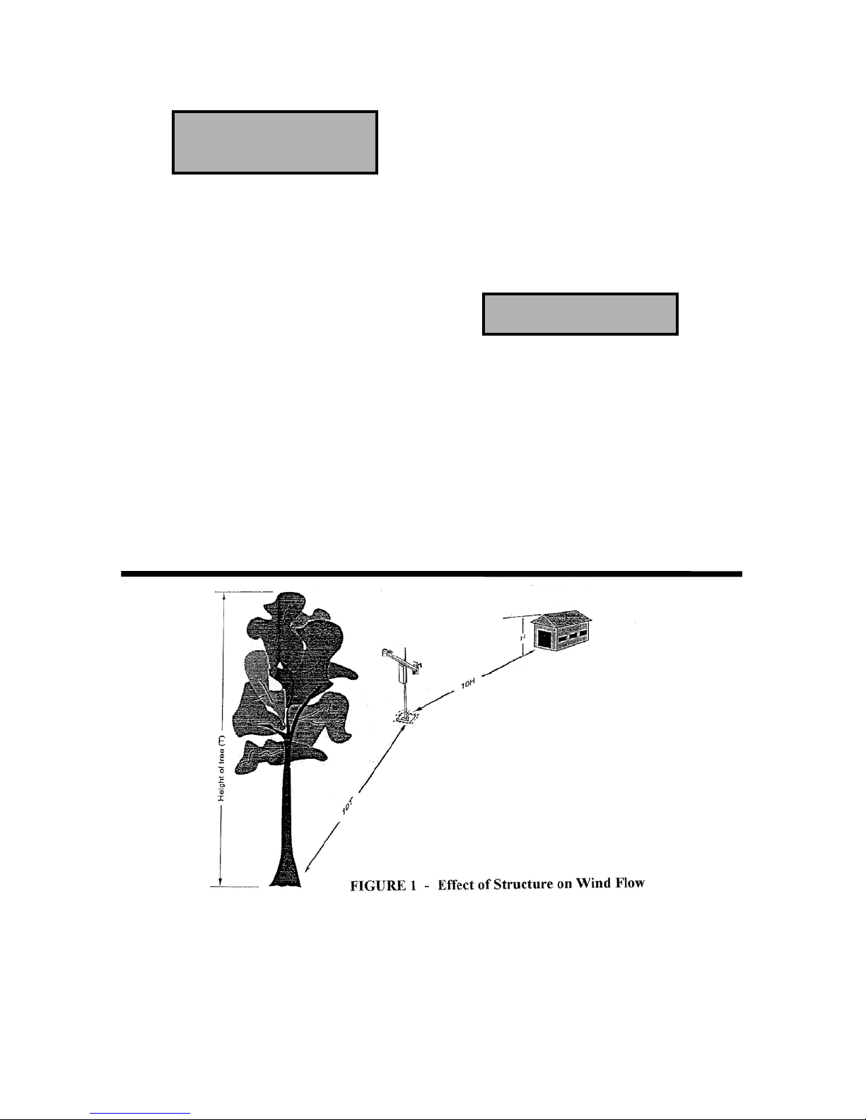
#1 Effect of Structure on Wind Flow...4
#2 Magnetic Declination for the Contiguous
United States......6
#3 Declination Angles.....8
#4 Concrete Base Detail.....11
#5 Anchor Bolt/Template Detail. . . 11
#6 External Wiring Detail at the PRO-SH Station . 14
#7 External Wiring Detail at the PRO-PH Station . 17
#8 Mounting ET Enclosure on Tower...18
#9 16VAC Connection & Rechargeable
Battery Installation....20
#10 Solar Pane Installation Detail...23
#11 Cross-Arm Mounting Detail....25
#12 Wind Sensor Installation Detail...27
#13 Temperature/RH Sensor Installation Detail. . 28
#14 Solar Radiation Sensor Installation Detail . . 29
#15 Sensor Cable Connections....30
#16 Sensor Switch Settings ....31
#18 Short Haul Modem Installation in ET Enclosure . 32
#19 Telephone Modem Installation in ET Enclosure . 34
Page vi
Page 9

Table of Figures Cont’d.
Figure # Description Page
#20 Desiccant Pack Installation....34
#21 Installation at Central Computer for Direct
Connected Weather Station....37
#22 Installation at Central Computer for
Telephone Connected Weather Station . . 39
#23 Using the ML 10-KD Keyboard Display . . 48
#24 Configuration of Serial Cable...52
#25 Test of Short Haul Modem....54
#26 Test of Communication Wires...55
#28 Typical 3-Rod Grounding Grid Detail . . 62
#29 Testing of Wind Sensor....63
#30 Testing of Solar Radiation Sensor...64
#31 Testing of Rain Gage.....65
#32 Testing of Temperature/RH Sensor...66
#33 Testing of Air Temperature Probe...67
Page vii
Page 10

Page viii
Page 11

WS-PRO Weather Station
1.0 GENERAL:
The Rain Bird “Model PRO” Weather
Station, when used in conjunction with
the Rain Bird MAXI 5, MAXI
“Nimbus” or MAXI “Cirrus” Central
Control system, provides the irrigation
manager with a powerful tool to aid in
the growing of lush, healthy, green
turfgrass, while conserving important
resources, such as water, power, etc.
The MAXI 5, MAXI Nimbus or MAXI
Cirrus software interrogates the Weather
Station to gather information that has
been gathered on a daily basis, on 5
second intervals for short haul modem
only, of the climatic conditions that
affect the irrigation application for the
area.
The MAXI 5, MAXI Nimbus or MAXI
Cirrus software subjects the climatic
information that it gathers to a version of
the modified Penman Equation. The
Penman Equation has been proven
through over 35 years of university
research, to be one of the most reliable
predictors of turfgrass water use
requirements.
The Weather Station monitors the
following climatic conditions:
Rainfall
Wind Speed & Direction
Air Temperature
Relative Humidity
Solar Radiation
The basic PRO Weather Station
configuration includes sensors to
monitor these conditions, a micrologger
to capture this data, a modem to
communicate the information to the
MAXI Central Computer and a power
supply.
The Rain Bird Model “PRO” Weather
Station is available in two (2) basic
configurations;
Model PRO-SH, which is a
direct wire system intended for
use when the weather station is
within 20,000 feet of the MAXI
Central Computer and
communication is via a wire
path, between the weather
station and the computer.
Model PRO-PH, which is a
phone modem system for use
when the weather station is
further than 20,000 feet from the
MAXI Central Computer or
when they cannot be connected
by a communication wire path.
The system communicates
utilizing a standard, dedicated
phone service.
Page 1
Page 12

2.0 TOOLS & SUPPLIES:
(Installer Supplied)
The installer needs access to the following tools and supplies for installation of the
Weather Station.
TOOLS REQ’D.
Shovel
SUPPLIES REQ’D.
Rake
Wire Strippers
Screw driver, regular blade
Flat Metal File
Screw driver, thin regular blade
Wheelbarrow
Screw driver, Phillips head
Hand Saw
Open End Wrench 7/16”
(2) - Open End Wrench 9/16”
Open End Wrench ½”
Open End Wrench 3/8”
Claw Hammer
Magnetic Compass
Tape Measure 12’ - 20’
Matr’l. for Concrete Base Form:
(4) 12” Wood Stakes
(1) 2”x 4”x 10’ piece of wood
(8) 8p double-head nails
(8)16p double-head nails
20 ft. of form wire
½ yard of concrete
6 Ft. Step Ladder
Concrete trowel & edger
Saw Horse
Wire
Fish Tape or small dia. rope
(2) Standard Size (12” x 18”)
Rectangular Valve Boxes
(3) MGP-1 Maxi Grounding Plate
Assembly
(5) MSP-1 Maxi Surge Arrestor (Pipe
Type) (for “PRO-SH” model ONLY).
(6) 5/8” Dia. X 8’-0” copper clad
grounding rods
#10 Gauge or larger bare copper
grounding wire - length as required.
Brass Grounding Clamps - as required
(20) 3-M model DBY or DBR Direct
Burial splice kits or 3-M Scotch-lok
3500 series Connector Packs.
Belden #9883 or PE-39 direct burial,
communication cable - length as
required.
(2) Lengths of type UF power wire
(white and black) - size and length as
required.
(1) 4” x 4” electrical junction box with
cover plus connectors as required for
transformer mounting.
(2) Open Spade, crimp-on type
connectors - for connecting power
wiring to transformer.
3.0
Page 2
Page 13

WEATHER STATION SITE SELECTION:
Site selection for the Weather Station is
one of the most crucial steps in a
successful installation and an efficiently
operating irrigation system. The site
selection will greatly impact the
accuracy of the meteorological data
collected by the station. The site
selection process has many constraints
placed on it, and although the “perfect”
site is often non-existent, the following
generalities should be kept in mind.
In general, the site should be
representative of the general area of
interest and reflect the general
conditions of the project’s turf. The
more “typical” the site, in this regard,
the more useful will be the information
gathered. The site should also be away
from the influence of obstructions such
as buildings, trees, etc.
The weather station should not be
located where sprinkler irrigation water
will strike sensors or instrument
enclosure. The turf around the weather
station needs to be irrigated however - so
it is recommended that half-circle
sprinklers be placed around the base of
the weather station and ”throwing OUT’
away from the weather station. In this
way the turf can be irrigated and at the
same time water can be kept off the
sensors and instrument enclosure of the
weather station.
The sensors of the weather station
should be eight (8) to ten (10) feet above
the turfgrass. Remember that the roof
of a building IS NOT a good site for the
weather station.
The weather station does NOT need to
be “hidden”. The Rain Bird weather
station has been engineered to be
aesthetically pleasing. The urge to
“hide” the station needs to be balanced
with the selection of the most “typical”
turfgrass area. The station should NOT
negatively impact the turfgrass
environment or utility. In fact, many
installations prominently display the
Weather Station to demonstrate their
commitment to water conservation.
If the site may be prone to vandalism,
an open, chain-link, 6 foot high
security fence with a lockable access
gate should be placed around the
weather station. The fence shall be a
minimum of eight (8) feet out from the
weather station on all sides and should
be a type that will not interfere with the
accuracy of the sensors.
In your selection of a site - try to avoid
sites on or near open dirt fields and
asphalt parking areas. These sites are
prone to high invective heats that can
distort the information. Any areas that
are within 90 to 100 feet “up wind” of
the weather station can adversely affect
the weather station reading accuracies.
The requirements of each weather
station sensor must be considered when
selecting the proper location for a
weather station site. In addition to these
generalities, each sensor has its own
specialized constraints. While complete
information is available, upon special
request, for each individual sensor, the
following are the highlights of each.
Page 3
Page 14
(a) TEMPERATURE AND
RELATIVE HUMIDITY:
Sensors should be located over an open
level turf area at least 30 feet in
diameter. The surface should be the
typical turfgrass of the area in interest.
Sensors should be located a distance
away of at least four (4) times the height
of any nearby obstruction and at least 90
feet from large paved areas. Sensors
should be protected from thermal
radiation, and adequately ventilated.
Situations to avoid include:
• large industrial heat sources
• rooftops
• steep slopes
• sheltered hollows
• high vegetation
• shaded areas
• top of a hill
• bottom of a swale
• swamps
• areas where snow drifts occur
• low places holding standing
water
(b) SOLAR RADIATION:
Pyranometers should be located to avoid
shadows on the sensor at any time.
Mounting it on the southern most
portion (northern hemisphere) of the
weather station will minimize the chance
of shading from other weather station
structures. Reflective surfaces and
sources of artificial radiation should be
avoided. The height at which the sensor
is mounted is not critical.
Page 4
Page 15
(c ) PRECIPITATION
A rain gage should be located over level
ground that is covered with short grass
or gravel. In open areas, the distance to
obstructions should be two to four times
the height of the obstruction.
The height of the opening should be as
low as possible, but should be high
enough to avoid splashing from the
ground.
The gage must be mounted above the
average level of snow accumulation in
areas that experience significant
snowfall.
Standard measurement heights:
1.0 meter +/- 1.0 cm (AASC)
30.0 centimeter minimum
(WMO, EPA)
(d) DETERMINING TRUE
NORTH FOR WIND
VANE OREINTATION
Magnetic declination, or other methods
to find True North, should be
determined prior to installing the
weather station. True North is usually
found by reading a magnetic compass
and applying the correction for magnetic
declination. (Other methods employ
observations using the North Star or the
sun, and are discussed in the Quality
Assurance Handbook for Air Pollution
Measurement Systems, Volume IV Meteorological Measurements.) The
magnetic declination is the number of
degrees between True North and
Magnetic North. Magnetic declination
for a specific site can be obtained from a
USFA map, local airport, or through a
computer service offered by the USFS
called GEOMAG (see page 7). A
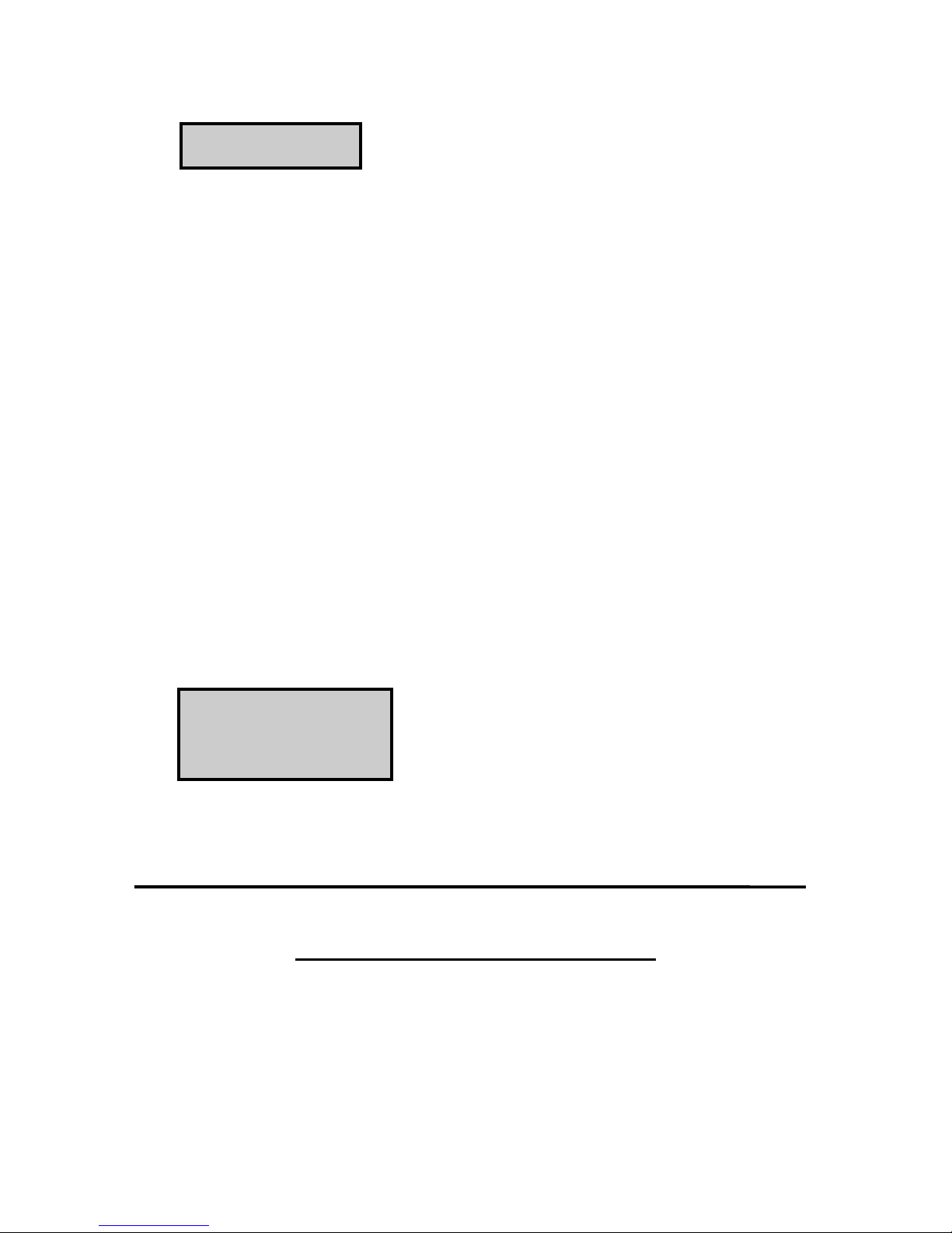
general map showing magnetic
declination for the contiguous United
States is shown below in FIGURE 2.
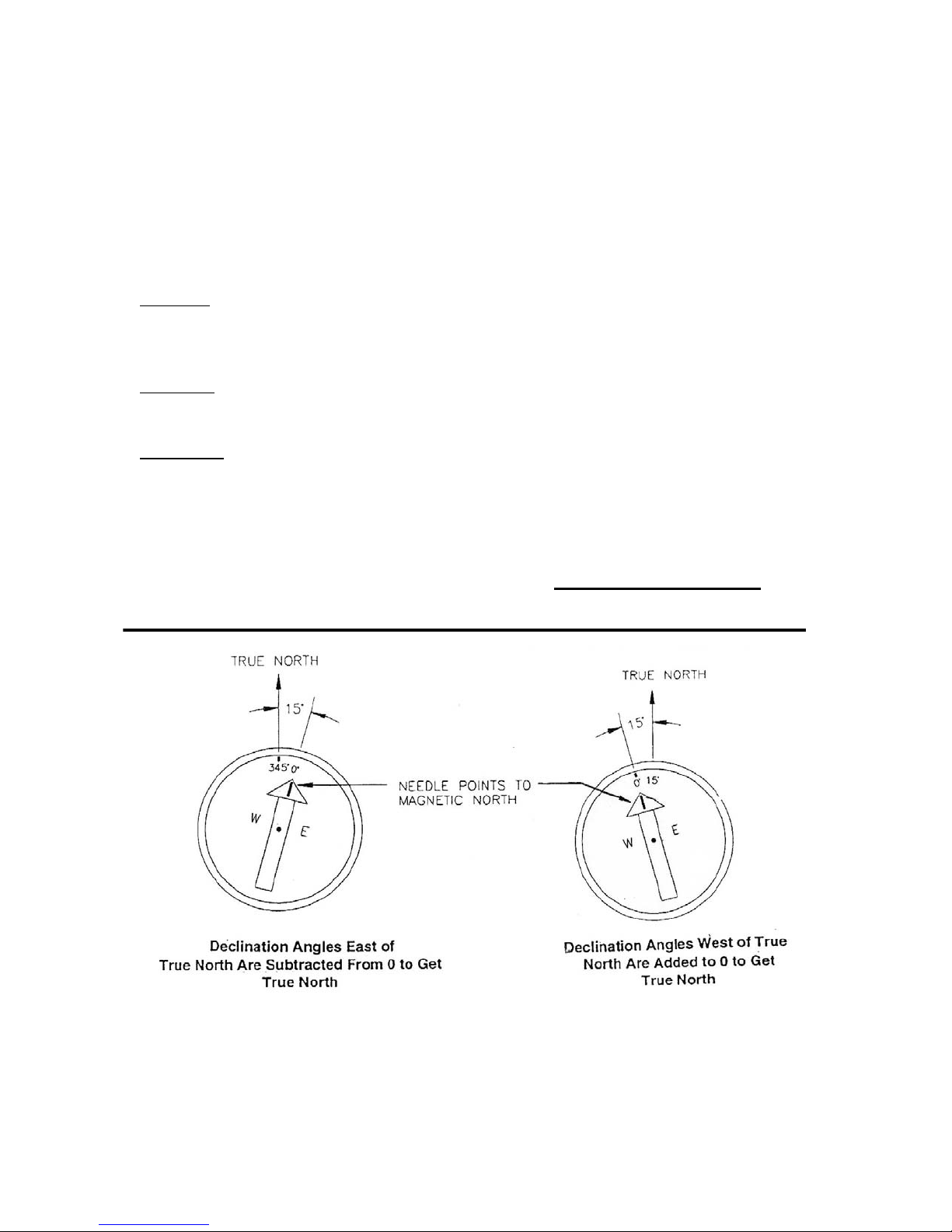
Declination angles east of True North
are considered negative and are
subtracted from 0 degrees to get True
North. Declination angles west of True
North are considered positive and are
added to 0 degrees to get True North.
For example, the declination for Logan,
Utah is 16 degrees East. True North is
360 degrees minus 16 degrees, or 344
degrees as read on a compass.
REFER TO NEXT PAGE FOR FIGURE 2
Page 5
Page 16
FIGURE 2 - MAGNETIC DECLINATION FOR THE
CONTIGUOUS UNITED STATE
Page 6
Page 17
PROMPTS FROM GEOMAG
GEOMAG is accessed by phone with a
PC and telephone modem and a
communications program such as Pro
Comm or Windows 95 Hyperterminal.
GEOMAG prompts the caller for site
latitude, longitude and elevation, which
it uses to determine the magnetic
declination and annual change. The
following information, menu and
prompts are from GEOMAG.
Username: QED
[RETURN}
Main Menu:
Type
Q for Quick Epicenter
Determinations (QED)
L for Earthquake Lists (EQLIST)
M for Geomagnetic Field
values (GEOMAG)
X to log out
GEOMAG is a user-friendly program
that provides estimates of the
geomagnetic field elements, including
declination and total field intensity,
based upon Magnetic Models. The
program is accessible by modem or
through the Internet.
Modem Access:
Modem settings: No parity, 8 data bits
and 1 stop bit (i.e., N81).
Telephone numbers:
Phone Number Baud Rates
303-273-8672 2400
303-273-8673 1200
303-273-8678 1200
Upon carrier-signal detection, press
Return once or twice.
ENTER program option: “M”
Would you like information on how to
run GEOMAG (Y/N)? Enter N
OPTIONS:
1 = Field Values (D,I,H,X,Z,F)
2 = Magnetic Pole Positions
3 = Dipole Axis and Magnitude
4 = Magnetic Center [1] : 1
Display values twice [N]: press return
Name of field model [USCON90]:
press return
Date [current date]:
press return
Latitude :42/2 N
Longitude : 111/51/2W
Elevation : 4454 ft
If you are using one of the commercial
numbers, the following prompts will
appear. Type the responses shown
(followed by pressing RETURN):
GLDSV1> c neis
[RETURN]
Page 7
Page 18
Example of report generated by
GEOMAG:
Model: USCON90 Latitude: 42/2 N
Date: 7/27/93 Longitude: 111/51/2W
Elevation: 4454.0 ft
Declination is:
deg min
15 59.6
Annual change:
deg min
0 -6.1
EXITING:
press “Cntrl-Z” to exit GEOMAG
When the main menu reappears either
select another option or Type “X” to log
out.
If you used one of the commercial
numbers, the GLDSV1> prompt will
reappear.
Type “LO” to disconnect.
Use of GEOMAG is free (except for
telephone charges). If possible, please
avoid using GEOMAG between 9 a.m.
and 4 p.m., mountain time, Monday
through Friday.
The declination in the example above is
listed as 15 degrees and 59.6 minutes.
Expressed in degrees, this would be
15.99 degrees. As shown in FIGURE 2,
the declination for Utah is east, so True
North for this site is 360 - 15.99, or 344
degrees. The annual change is -6.1
minutes.
Refer to FIGURE 3 below:
FIGURE 3 - DECLINATION ANGLES
Page 8
Page 19
4.0 WEATHER STATION CONCRETE BASE:
SUPPLIED COMPONENTS
(1) 2” x 4” x 10’-0” piece of
forming lumber
(3) ½” x 12” long “L” Anchor
Bolts
(9) ½” Nuts
(3) Flat Steel Washers
(4) 16p Double Headed nails
10’-0 “ length of form wire
½ yard of concrete
Duct Tape
(1) Stainless Steel Template
(1) 1 ½” Dia. Long Sweep
TOOLS REQUIRED
Elbow
Claw Hammer
INSTALLER SUPPLIED
Hand Saw
Saw Horse
Shovel
Pliers & Wire Cutters
INSTALLATION:
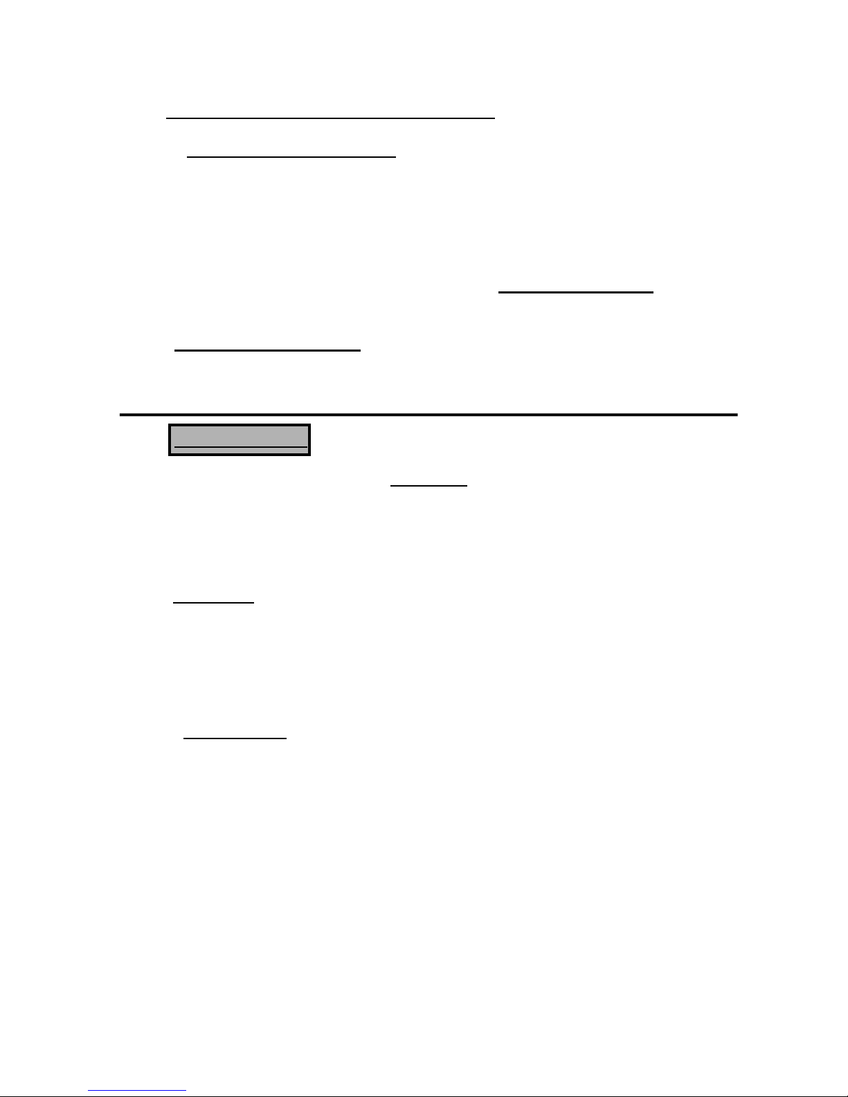
For the following procedures - Refer to FIGURE 4 below.
1.0 The Tower for the “PRO”
4.0 Construct the concrete form
Weather Station - attaches to a user
supplied poured concrete
foundation - constructed as shown
in FIGURE 4 below.
2.0 Dig the required foundation
hole - with a 24” square top
and slanting outward sides, to the
bottom of 32” square. The
“Sloping” sides of the foundation are
very IMPORTANT in providing the
necessary support to the weather
station tower, in preventing it from
5.0 Place a piece of duct tape
“leaning” or falling over, due to
wind load on the station.
3.0 Determine the proper location of the
long sweep elbow and dig a small
cavity to accept the end of the elbow
that will protrude beyond the
concrete base.
with 2” x 4” lumber and 16p
double-headed nails.
Center the form over the dug
hole. Adjacent to the long
legs of the form that extend
beyond the hole, drive four
stakes into the soil. Level
the form. Secure the form
to the stakes with 8p nails making sure that the form
remains “level”.
over one end of the 1 ½”
diameter long sweep elbow.
Insert the elbow into the
hole, with the taped end
into the small cavity that
you have dug on one side of
the hole.
Page 9
Page 20

6.0 Insert the other end of the long
sweep elbow into the center hole in
the stainless steel template. Tape
the end of the elbow with duct tape.
7.0 Take the three ½” x 12” long “L”
anchor bolts and install two (2) hex
huts on to each bolt. Insert one in
each of the holes in the template and
install one of the flat washers and a
nut to secure the anchor bolt to the
template.
Refer to FIGURE 5.
8.0 Take the form wire and cut it into
two (2) equal lengths. Attach one
end of one of the wires to one of the
16p nails on the form. String the
wire up over the form and to the long
sweep elbow - making a turn around
it. Continue the wire over to the
16p nail at the other corner of the
form (located on the same side of the
form as the other nail) and centering
the template and elbow attach the
wire securely to the nail. Repeat
this same process with the other
piece of form wire - going to the
opposite nails and further securing
the template, elbow and anchor bolts
in the form.
9.0 Steady the template assembly by
putting a 2” spacer between the
template and the top of the form.
Pour the concrete into the hole and
form - it will require approximately
½ yard - screed the concrete level
with the top of the form. Check to
make sure the template is correctly
orientated and centered. The bottom
of the anchor bolt threads should be
about ½” above the top of the
concrete. Check to be sure the
template is “level” in two (2)
dimensions. Use a trowel and edger
to finish the concrete.
BE SURE THAT YOU HAVE THE
TEMPLATE PROPERLY
ORIENTATED IN RESPECT TO
“NORTH”. Refer to FIGURE 4.
The template should have the two (2)
bolt holes, that are parallel with one
side of the template, on the north
side of the base.
10.0 Wait 24 hours before removing the
concrete form. Wait 7 days before
mounting the weather station to the
base.
REFER TO NEXT PAGE FOR FIGURES 4 & 5
Page 10
Page 21
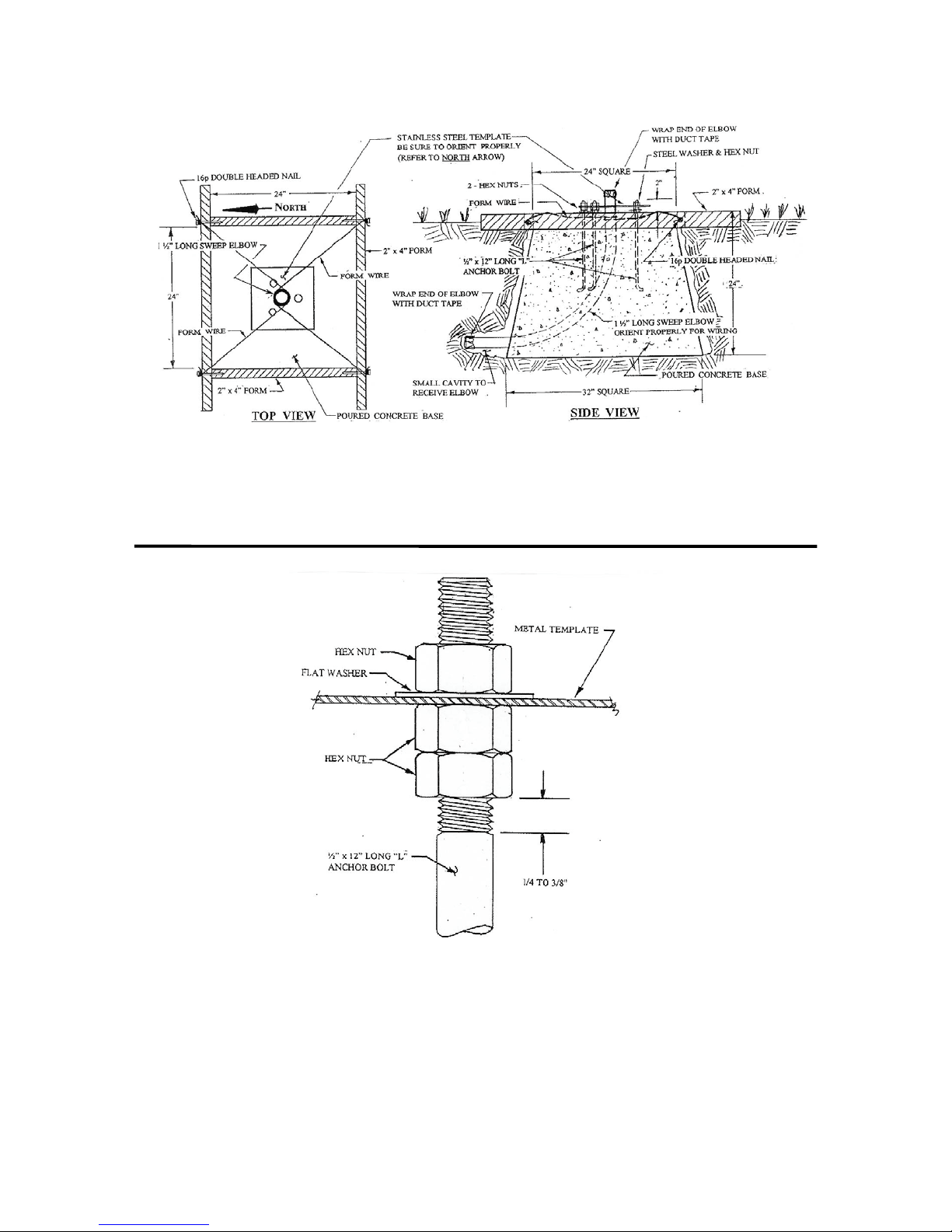
FIGURE 4 - CONCRETE BASE DETAIL
FIGURE 5 - ANCHOR BOLT/TEMPLATE DETAIL
Page 11
Page 22
5.0 EXTERNAL WIRING TO WEATHER STATION: ( Refer to FIGS. 6 & 7)
WIRING VALVE ACCESS BOX
At the base of the Weather Station and
as near to the base as feasibly possible,
dig a hole large enough to install a
standard 18” x 24” rectangular valve box
and cover. The valve box shall
accommodate all wiring connections,
one rod of a 3-rod grounding grid,
MGP-1 grounding plate assemblies and
MSP-1 surge arrestors.
WEATHER STATION
POWER WIRING
Furnished as part of the Weather Station
is a 120VAC to 16VAC power
transformer. This transformer can be
located in the pedestal of a field satellite
controller that is in the near proximity of
the weather station or some other
convenient weather proof location.
Install the transformer in a 4”x 4” metal
electrical box with cover. Connect the
120VAC power wires of the transformer
to a source of 120VAC power that is not
easily turned off. To the output of the
transformer, connect a pair of UF wires,
of proper size, using “crimp-on” open
spade connectors.
The power wires shall be direct buried
and run over to the weather station.
Connect the 16VAC power wires to the
“LINE” side of an MSP-1 surge
arrestor, which shall be mounted in an
MGP-1 grounding plate assembly. The
MGP-1
grounding plate assembly shall be
securely mounted on a 5/8” dia. copper
clad, ground rod - one of a 3-rod
grounding grid.
NOTE ! The minimum voltage to
the transformer shall be not less than 112
volts.
Wire sizing shall be in accordance with
the chart given below.
Wire shall be Type “UF” (underground
feeder cable) with PVC insulation. The
16VAC power is used to provide
constant charging of the battery within
the weather station, through the battery
charging circuit.
WIRE SIZING CHART
WIRE SIZE DISTANCE
(feet)*
18 500
16 800
14 1275
12 2000
10 3250
8 5100
* Transformer to Weather Station
The “EQUIPMENT’ side of this MSP-1
surge arrestor shall be connected to
“red” and “black” wires of the 20’power
wire cable, which is furnished as part of
Page 12
Page 23
the weather station, and MARKED
“P/N 9922”. This cable shall be routed
through the 1 ½” dia. long sweep elbow
to the base of the weather station. All
wire connections and splices in the
power wiring shall be made using 3-M
DBY direct burial connectors. DO
NOT apply power to transformer at this
time.
WEATHER STATION
COMMUNICATION WIRING
DIRECT CONNECTED - USING
SHORT HAUL MODEMS:
(MODEL PRO-SH - Only)
cable furnished with the weather station
and marked P/N 9720 “ET SHORT
HAUL” “COMM”.
The RED (+RCV) & BLACK (-RCV)
pair shall be connected to the RED &
BLACK wires respectively, at the
“LINE” end of the other MSP-1 surge
arrestor. The RED (+RCV) and the
BLACK (-RCV) wires from the
“EQUIPMENT” end of this MSP-1
surge arrestor shall be connected to the
RED (+RCV) and the BLACK (-RCV)
wires of the communication cable
furnished with the weather station and
marked P/N 9720 “ET SHORT HAUL”
“COMM”.
Coming from the Central location,
furnish and install a Belden #9883,
Direct Burial Type, communication
cable over to the weather station
location. The Belden cable shall consist
of three (3) twisted pair of wires (20
Gauge), a bare copper drain wire and an
aluminum shield. The three (3) twisted
pair shall be color coded as follows; 1
pair “black” and “white”, 1 pair “black”
and “green” and 1 pair “black” and
“red”.
The BLACK (-XMT) & GREEN
(+XMT) pair shall be connected to the
BLACK & RED wires respectively, at
the “LINE” end of one of the MSP-1
surge arrestors. The BLACK (-XMT)
and the RED (+XMT) wires from the
“EQUIPMENT” end of this MSP-1
surge arrestor shall be connected to the
WHITE (-XMT) and the GREEN
(+XMT) wires of the communication
This communication cable shall be
routed through the 1 ½” diameter long
sweep elbow to the base of the weather
station. All wire connections and
splices in the communication wiring
shall be made using 3-M DBY direct
burial connectors. DO NOT attempt to
use any other type connectors as
communication signal may be impaired
and poor communication resulting.
GROUNDING
COMMUNICATION CABLE
The bare copper drain wire of the Belden
cable shall be grounded to the grounding
rod, using a brass ground wire clamp.
IMPORTANT ! DO NOT ground the
drain wire at the Central end of the cable
- just leave the drain wire un-used.
Page 13
Page 24
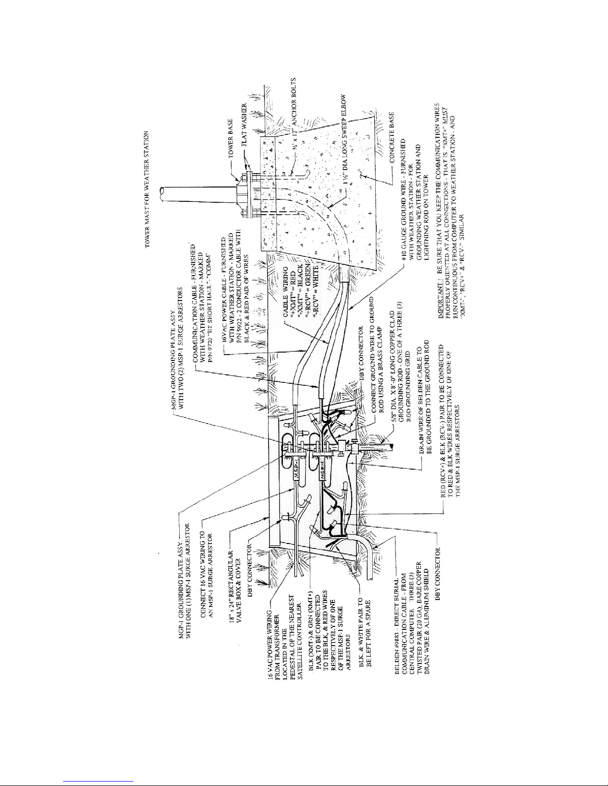
FIGURE 6 - EXTERNAL WIRING DETAIL AT THE
PRO - SH WEATHER STATION
Page 14
Page 25

WEATHER STATION
COMMUNICATION WIRING
TELEPHONE CONNECTED - USING
TELEPHONE COMPANY LINES:
(MODEL PRO-PH - Only)
The Telephone Company needs to run a
of the telephone patch cable (P/N 9661).
direct burial telephone cable to the
weather station and terminate it near the
base of the weather station. This needs
to be a modem quality type telephone
line with a separate call number.
Splices shall be made using 3-M DBY
Direct Burial connectors. The splices
for the phone line shall be made in the
valve box, where the power wiring
splices are made and where the MGP-1
The “TIP” line of the telephone cable
shall be connected to the WHITE
(“TIP”) wire of a 20’telephone patch
cable, furnished as part of the weather
grounding plate assembly with an MSP-
1 surge arrestor mounted in it, is
attached to one rod of a 3-rod grounding
grid. Refer to FIGURE 7 below.
station, marked P/N 9661 - 2 conductor
cable with WHITE (“TIP”) and BLACK
(“RING”) pair of wires. The “RING”
line of the telephone cable shall be
connected to the BLACK (“RING”) wire
This telephone patch cable (P/N 9661)
shall be routed through the 1 ½”
diameter long sweep elbow to the base
of the weather station.
6.0 TOWER ASSEMBLY AND INSTALLATION:
INSTALLATION
SUPPLIED COMPONENTS
(1) Upper Tower Section
(Tapered)
(2) Lower Tower Section w/Base
(6) ½” Washers
(1) 12 foot 10 AWG Ground
Cable
(1) Tower Plastic Cap
Take the 12 foot 10 AWG Ground
Cable, furnished as part of the weather
station and cut a 9” piece from on end of
it. (This 9” piece will be used later).
Attach one end of the ground wire to the
ground rod, of the 3-rod grounding grid,
that is located in the valve box using a
brass clamp. Refer to FIGURE 6 or 7.
Feed this ground wire through the 1 ½”
long sweep elbow up to the base of the
weather station.
Page 15
Page 26

Remove the three (3) “top” nuts and flat
washers from the anchor bolts at the
weather station template. Next remove
the metal template - slipping it up over
the cables that are extending from the
1 ½’ long sweep elbow. Be careful
NOT to damage the cables or the
connectors on the cables.
Take the lower section (with the base
attached) of the weather station tower
and feed, from the base end, the power
cable (P/N 9922) up through this section.
Also feed, from the base end, the short
haul communication cable (P/N 9720 for the Model JR-SH weather station) or
the telephone communication patch
cable (P/N 9661 - for the Model JR-PH
weather station, up through this section
of the tower. Finally feed the ground
wire up through the lower section of the
tower.
Lay this Lower Section of the tower, on
the ground, next to the concrete base,
with the cables extending out the top of
the tower section.
Take the Upper Section of the tower (the
tapered section) and position it above the
lower section on the ground. Feed the
cables, coming from the lower section,
up through the upper section of the
tower. Secure the cables at the top of
the upper section with tape, so that they
cannot pull back down into the tower as
you assemble the two tower sections.
Now assemble the upper tower section
to lower tower section, being careful
NOT to damage the cables as you do so.
IMPORTANT ! Be sure that you have
everything in proper order BEFORE
you assemble the two tower sections
together -because once assembled they
cannot be taken apart.
Place one of the flat washers on top of
the two (2) nuts on each of the anchor
bolts. Raise the tower and position the
base on the three (3) anchor bolts that
have been embedded in the poured
concrete base. Be careful NOT to
damage the cables in doing so. Next
install a flat washer and a nut on each of
the bolts and hand tighten the nuts just
enough to hold the tower in position.
Next check the level of the tower by
placing a level on the north and east
sides of the lower tower base. Adjust
the topmost nut of the two (2) lower nuts
(leveling nuts) on each bolt, as
necessary to level the base. When level
is established, lock the leveling nut in
place by tightening the lowest nut
against it. Tighten the three top nuts
with a wrench to secure the tower to the
base. The tower should now be ready
for the final assembly of the Enclosure,
Sensors and Lightning Rod, etc.
REFER TO NEXT PAGE FOR FIGURE 7
Page 16
Page 27

FIGURE 7 - EXTERNAL WIRING DETAIL AT THE
PRO - PH WEATHER STATION
Page 17
Page 28

7.0 INSTRUMENTATION ENCLOSURE INSTALLATION:
GENERAL:
The Model PRO weather station
datalogger, power supply, sensor
connection panel, communications
devices and data retrieval peripherals are
mounted in the ET Enclosure with the
sensors themselves mounted on a crossarm, which mounts to the top of the
Enclosure.
MOUNTING
ET ENCLOSURE TO THE
TOWER
Mount the Enclosure to the top of
the weather station tower, by sliding the
enclosure brackets down the tower,
from the top of the tower.
Position the Enclosure so that the top of
the enclosure is even with the top of the
tower and on the north side of the tower
(for northern hemisphere). Tighten the
bolts, on the clamps, to secure the
enclosure to the tower. DO NOT over-
tighten the bolts since doing so may
damage the tower or the enclosure.
Refer to FIGURE 8 below
FIGURE 8 - MOUNTING ENCLOSURE ON TOWER
Page 18
Page 29

INSTALLATION OF
LIGHTNING ROD
Refer to FIGURE 8 above:
Carefully mount the lightning rod
bracket, furnished with the weather
station, to the top of the weather station
tower. Locate it above the Enclosure
top bracket and near the top of the tower.
Clearance between the clamp and the
Enclosure is minimal. Care should be
taken not to scratch the enclosure or
sensor assembly. Insert the lightning
rod into the bracket, with approximately
½” to 1” of the rod extending below the
bracket, and tighten the set screw to
secure the rod in the bracket.
Take the ground wire, that has been fed
up the weather station tower, strip the
insulation from the end and curl the end
so as to be able to connect the wire
under the head of one of the bolts on the
lightning rod bracket. Be sure that you
wrap this wire completely around the
bolt and that you get a good contact with
the bolt and bracket. Tighten the bolt
securely so that you have a good tight
connection. This connection is
EXTREMELY important to give
maximum protection to the weather
station against damage from lightning
surges. This connection should be
INSPECTED on a regular basis to
assure it remains tight and making good
contact.
Take the 9” piece of ground wire, that
you previously cut off the ground wire,
and strip the insulation from each end of
it. Insert one end of this wire into the
brass grounding lug, located at the top
of the Enclosure on the back panel.
Tighten the set screw to secure the wire
in the clamp. Curl the other end so as to
be able to place it around the other bolt
of the lightning rod bracket. Be sure that
you wrap this wire completely around
the bolt and that you get a good contact
with the bolt and bracket. Tighten the
bolt securely so that you have a good
tight connection. This connection is
EXTREMELY important to give
maximum protection to the weather
station against damage from lightning
surges. This connection should be
INSPECTED on a regular basis to
assure it remains tight and making good
contact.
POWER SUPPLY
RECHARGEABLE BATTERY
The weather station is furnished as
standard with a Sealed Rechargeable
Battery and including the mounting
bracket. This battery is to be installed
on the back panel of the Enclosure.
Refer to FIGURE 9 below.
Page 19
Page 30

FIGURE 9 - 16VAC CONNECTION AND RECHARAGEABLE BATTERY
INSTALLATION
with the screws. Tighten all four screws
Loosen the four (4) screws located on
the back panel of the Enclosure. Slip
the end of the battery bracket, that has
the two (2) keyhole slots in it over the
to properly secure the battery to the back
panel of the ET Enclosure.
upper two (2) screws. Line up the
battery bracket slotted holes, in the
other end of the bracket, with the two
(2) lower screws. Now push “down” on
the battery - seating the bracket in place
Plug the connector on the wire leads of
the battery to the “top” battery
connection - marked “LA” - which is
located on the Enclosure panel
assembly just above the battery location.
Page 20
Page 31

AC EXTERNAL
POWER WIRING
the cap on the Heyco fitting to seal
around the cable. The wires can be
Refer to FIGURE 8 & 9 above:
attached to these connectors by
“depressing” the lever on the connector
for each wire and while doing so, insert
The 16VAC power wiring, that you
have fed up through the weather station
tower, shall be routed down the back
side of the Enclosure and into the
Enclosure through the Heyco fitting,
marked “power”. Unscrew the cap of
the Heyco fitting (on the back side of the
enclosure) and push the plug out of the
fitting. This plug can be discarded as it
will not be used. Feed the power wires
through the Heyco fitting and connect
them to the the connectors of the
the stripped end of the wire. Upon
release of the lever, the wire will be
secured in the connector. CAUTION !
Be careful in depressing the lever so as
not to break the lever. The polarity of
the 16VAC power wiring does not
matter, therefore it makes no difference
which wire goes into which connector.
At this point you can now connect the
power to the transformer or wait until
you have connected the sensors, which
ever you prefer.
Enclosure, marked “CHG”. Tighten
It will be noted that on the panel assembly there are connectors marked “ALK”.
These connectors are NOT to be USED. The use of an Alkaline battery is NOT an
option.
CONTINUE ON THE NEXT PAGE
POWER SUPPLY
Page 21
Page 32

OPTION
SOLAR PANEL
Refer to FIGURE 10 below:
Model Numbers shall be as; PRO-SH-SP
or PRO-PH-SP. (SP designating the
Solar Panel Option).
An option is for use of a Solar Panel, for
the power supply, rather than the
standard 120VAC/16VAC transformer.
Mount the solar panel to the weather
station tower using the mounting
brackets furnished as part of the solar
panel assembly. Mount the solar panel
to the tower so it faces south (northern
hemisphere). Position the solar panel as
high off the ground as practical,
ensuring it cannot interfere with air flow
or sunlight around the sensors.
The solar panel should be oriented to
receive maximum sun light exposure
over the course of the year. It is also
necessary that the solar panel have the
proper “tilt”. Suggested “tilt” angles
(reference to the horizontal plane) are
listed below.
Site Latitude Tilt Angle
0 to 10 degrees 10 degrees
11 to 20 deg. Latitude +5
degrees
21 to 45 deg. Latitude +10
degrees
46 to 65 deg. Latitude +15
degrees
65 deg. 80 degrees
After determining the “tilt” angle,
loosen the two (2) bolts that attach the
solar panel to the mounting bracket.
Adjust the angle of the solar panel, then
tighten the bolts to secure it in the proper
position. Secure the lead wire, coming
from the solar panel, to the Tower mast
using wire ties.
The solar panel cable shall be routed up
and through the Heyco fitting on the
back panel of the Enclosure and marked
“power”. Unscrew the cap of the Heyco
fitting (on the back side of the enclosure)
and push the plug out of the fitting.
This plug can be discarded as it will not
be used. Now feed the solar panel
power cable through the Heyco fitting
and connect it to the connectors of the
Enclosure, marked “CHG”. The wires
can be attached to these connectors by
“depressing” the lever on the connector
for each wire and while doing so, insert
the stripped end of the wire. Upon
release of the lever,, the wire will be
secured in the connector. CAUTION !
Be careful in depressing the lever so as
not to break the lever. The polarity of
the wires does not matter, therefore it
makes no difference which wire goes
into which connector. The solar panel
installation should now be completed.
Page 22
Page 33

FIGURE 10 - SOLAR PANEL INSTALLATION DETAIL
Page 23
Page 34

8.0 INSTALLATION OF INSTRUMENTATION
GENERAL:
The Model PRO weather station comes
with the some of the sensing
instruments, and sensor wiring to
datalogger completely assembled as a
unit on a cross-arm. The Solar
Radiation Pyranometer - along with the
leveling device are mounted on a
bracket, which in turn is mounted on the
cross-arm of the Enclosure. On this
end of the cross-arm the “Tipping Rain
Bucket” is also mounted at the factory.
On the opposite end of the cross-arm is
attached the mounting bracket, which
has been factory installed, for the Wind
speed and Wind direction sensing
instruments. The Temperature and
Relative Humidity sensors are on the
end of their cable and only need
installing into the radiation shield. The
cables for each of these sensors are
mounted in the cross-arm and terminated
at the proper location of each sensor.
The cables only need to be routed and
plugged into the proper connectors on
the back of the back panel of the ET
Enclosure.
SUPPLIED COMPONENTS
(1) Sensor Cross-Arm
(1) Met One 034A Wind Sensor
(1) 034A Mounting Shaft
(1) Radiation Shield
INSTALLATION OF CROSS-ARM
TO ET ENCLOSURE:
Refer to FIGURE 11 below:
Remove the four (4) Phillips head
screws from the bottom center of the
cross-arm. With the Enclosure cover
removed, place the cross-arm on top of
the Enclosure. The cross-arm needs to
be oriented along a due east to due west
axis. If necessary adjust the Enclosure
on the tower to properly orient the cross-
arm. Also be sure that the opening in
the middle and one side of the cross-
arm, where the sensor cables exit, is to
the back of the Enclosure so that the
cables can enter the top of the cover that
fits over the cable connectors on the
back of the Enclosure. Line up the four
threaded holes on the under side of the
cross-arm (where you just removed the
screws) with the four holes in the top of
the Enclosure. Attach the cross-arm to
the Enclosure by inserting the four (4)
screws, from in side the enclosure up
through the top and into the threaded
holes of the cross-arm. Tighten the
screws securely.
REFER TO NEXT PAGE FOR FIGURE 11
Page 24
Page 35

FIGURE 11 - CROSS-ARM MOUNTING
INSTALLATION OF 034A WIND SENSOR:
Page 25
Page 36

Refer to FIGURE 12 below:
With the Sensor Cross-Arm securely
installed to the Enclosure you are ready
to install the 034A Wind Sensor
instrument. The wind vane is oriented
after the datalogger has been
programmed and the location of True
North has been determined. Orientation
is most easily done with two people,
one to aim and adjust the sensor, while
the other observes the wind direction
displayed by CR10KD Keyboard
Display or a laptop PC computer.
Remove the aligning screw from the
base of the 034A wind sensor unit.
Place the 034A wind sensor into the
mounting shaft, that is clamped to the
end of the sensor cross-arm by means of
a U-Bolt clamp.
(The short, black mounting shaft,
included with the 034A wind sensor will
NOT be used).
Secure the 034A wind sensor in the
mounting shaft, by aligning the threaded
hole in the wind sensor with the hole in
the side of the mounting shaft, and reinstalling the aligning screw.
Next loosen the set screw in the top of
the 034A wind sensor (the set screw
opposite the one securing the wind
direction point). Place the end of the
wind vane into the hole. Properly orient
the vane to be in a true vertical position
and secure it by tightening the set screw.
Attach the wind sensor cable connector
to the connector on the 034A wind
sensor.
Without allowing the mounting shaft for
the 034A wind sensor to “slip down” (it
may be a good idea to mark the position
of the U-Bolt on the shaft so that you
can correctly position it should is “slip”)
slightly loosen the nuts of the “U-Bolt”
clamp of the mounting shaft - just
enough so you can rotate the mounting
shaft but not allow the shaft to “slip
down”.
Establish a reference point on the
horizon for True North.
Sighting down the instrument center
line, aim the counter weight at True
North. Display input location #8 for
wind direction, using the *6 Mode of
the datalogger.
REFER TO NEXT PAGE FOR FIGURE 12
While holding the wind vane position,
slowly rotate the sensor base/mounting
shaft until the datalogger indicates 0
degrees. Securely tighten the clamp
nuts.
Page 26
Page 37

FIGURE 12 - WIND SENSOR INSTALLATION DETAIL
HUMIDITY / TEMPERATURE
SENSOR AND RADIATION
SHIELD:
INSTALLATION OF RELATIVE
Refer to FIGURE 13 below:
Page 27
Page 38

On the bottom of the Cross-Arm, on the
end where the wind sensor has been
installed, remove the two screws for the
Relative Humidity/Temperature sensor
Radiation Shield.
Un-tape the RH/Temperature sensor
from the bottom of the Cross-Arm.
Remove the “yellow” protective plastic
cap from the end of the sensor, by
slipping it off the end of the sensor.
This can be discarded as it will not be
used.
Insert the RH/Temperature sensor into
the end of the shaft of the Radiation
Shield. Insert it to a depth where it is
securely seated. Now secure the
Radiation Shield to the bottom of the
sensor Cross-Arm with the two (2)
screws you have previously removed.
FIGURE 13 - TEMPERATURE/RH SENSOR INSTALLATION DETAIL
INSTALLATION OF SOLAR
RADIATION PYRANOMETER:
Refer to FIGURE 14 below:
Page 28
Page 39

The Solar Radiation Pyranometer, (with
the leveling device) is mounted, at the
factory, on a mounting bracket at the
opposite end of the cross-arm near the
Tipping Rain Bucket gage. By using
the three (3) leveling screws - level the
Pyranometer. After leveling - remove
the “RED” protective cap from the
Pyranometer.
FIGURE 14 - SOLAR RADIATION SENSOR INSTALLATION DETAIL
Refer to FIGURES 12 & 15:
SENSOR CABLE CONNECTIONS:
The Sensor Cables exit from the center
back of the Cross-Arm. The cables
need to be routed down the back of the
Page 29
Page 40

Enclosure and plugged into the
connectors on the back panel of the
Enclosure as follows:
Temp/RH #10090 cable - connect
to #1 connector [labeled
“TEMP/RH”]
Solar Radiation #10105 cable -
connect to #3 connector [labeled
“SOLAR RADIATION”]
Rain #10094 cable - connect to #5
connector [labeled “RAIN
(PRECIP)”]
WD/WS (Wind Direction/Wind
Speed) #10408 cable - connect to
#2 connector [labeled “WS/WD”]
Making sure that all cables are properly
enclosed behind the cover - replace the
cable cover. Be sure that you do not
pinch any of the cables between the
cover and the back panel of the
Enclosure.
FIGURE 15 - SENSOR CABLE CONNECTIONS
Page 30
Page 41

CONFIGURE SENSOR SWITCH
SETTINGS:
Refer to FIGURE 16 below:
The Sensor Switches are located on the
ET Enclosure panel just below the
modem and to the right of the the “Heat
Sink” located to the right of the battery
connectors. These switches or pots
need to be set as indicated in FIGURE
16 below.
FIGURE 16 - SENSOR SWITCH SETTINGS
SHORT HAUL MODEM
INSTALLATION
Refer to FIGURE 18 below: (PRO-SH)
The Short Haul Modem, at the weather
station, is normally installed at the
factory in the ET Enclosure. The Short
Haul Modems enable communication
between the datalogger and the central
computer over two (2) twisted pairs of
wires. The maximum distance between
modems is determined by the baud rate
and the wire gauge. At 9600 baud, the
approximate range is 4.0 miles. DCE/
DTE switches on the modems must be
set to DCE.
INSTALLATION:
For installation of the Short Haul RAD
Modem inside the Enclosure, the
following components are provided in
the Short Haul modem kit:
SC932C Interface w/ribbon cable
RAD Modem
RAD/SC932C Mounting Bracket
Velcro Mounting Strap w/Buckle
Mounting Screws
12 inch 4-wire Patch Cable
Partially install three (3) of the furnished
screws in the holes on the left side of the
Enclosure housing for the datalogger.
Hold the Modem mounting bracket in
the position it will be in the Enclosure.
Page 31
Page 42

Thread the Velcro mounting strap
through the two outer slots of the lower
set of slots in the modem mounting
bracket. Thread from the top down on
the far left slot first. The side of the
strap with Velcro should be facing
“down” toward the datalogger housing.
Then carry the strap across the back of
the bracket and thread it to the front of
the bracket through the far right slot of
the lower set of slots.
Slide the bracket flange, with the three
screw slots, under the heads of the three
(3) mounting screws you have partially
installed in the holes on the left side of
the datalogger housing. With the
bracket fully seated tighten the three (3)
screws to secure the mounting bracket to
the datalogger housing.
Connect the SC932C Interface to the
RAD Modem. Position this assembly
on the mounting bracket with the
SC932C Interface pointing “down”.
Strap the SC932C Interface unit securely
to the mounting bracket, using the
Velcro strap.
Connect the SC932C 9-pin port to the
internal Enclosure 9-pin port (located
just below the Phone Modem port) using
the blue ribbon cable provided.
Wire the RAD modem to the Enclosure
with the 12 inch 4-wire patch cord
provided. Black (-XMT) wire to -XMT
connections at the RAD modem and at
the connector on the Enclosure. The
RED (+XMT) wire to the +XMT
connections, the White (-RCV) wire to
the -RCV connections and the Green
(+RCV) wire to the +RCV connections
at the RAD modem and at the terminal
blocks: RED to +RCV, Black to -RCV,
Green to +XMT, White to -XMT.
Page 32
Page 43

FIGURE 18 - SH MODEM INSTALLATION IN ET ENCLOSURE
TELEPHONE MODEM
INSTALLATION
Refer to FIGURE 19 below:
(PRO-PH)
The Telephone Modem, at the weather
station, is normally installed at the
factory in the Enclosure. The
telephone modems enable
communication between the datalogger
and a Hayes compatible modem at the
Page 33
Page 44

central computer over a dedicated
telephone line. Phone line surge
protection is built into the Enclosure.
INSTALLATION
For installation of the phone modem
inside the Enclosure, the following
components are provided in the modem
kit:
COM200 or COM 300 Modem
12 inch RJ-11 Patch Cord
Modem Mounting Bracket
Mounting Screws
12 inch #14 AWG Ground Wire
4 Screws and Nuts
Partially install three (3) of the furnished
screws in the holes on the left side of the
Enclosure housing for the datalogger.
in the bracket over the top two (2)
screws that you have previously installed
in the datalogger housing. Be sure the
open slot in the bracket is in line with
the lower screw. Seat the modem
properly and tighten the screws to secure
the modem to the datalogger. Connect
the 9-pin connector of the Blue Ribbon
Cable to the phone modem 9-pin port.
Connect the other end of the ribbon
cable to the 9-pin port (marked “CS
I/O”) on the Enclosure. Secure it with
the two screws on the connector.
Connect the modem RJ-11 Patch Cord to
the RJ-11 jack on the phone modem
(located to the right of the 9-pin port).
Connect the other end of the RJ-11 Patch
Cord to the RJ-11 jack on the
Enclosure, marked “phone modem”.
Attach the phone modem to the
mounting bracket, using the four screws
and nuts.
Taking the phone modem and bracket
assembly - install the two keyhole slots
REFER TO NEXT PAGE FOR FIGURE 19
Connect one end of the 12 inch #14
AWG ground wire to the terminal,
marked “GND” and located on the right
side of the phone modem. Connect the
other end of this ground wire to the
connector on the Enclosure that is
marked “GND”.
The installation of the phone modem is
now completed.
Page 34
Page 45

FIGURE 19 - TELEPHONE MODEM INSTALLATION IN ET ENCLOSURE
latch for extra security.
9.0 SEALING & DESICCATING
THE ENCLOSURE:
The Enclosure is supplied with a
desiccant pack. The desiccant
maintains a low humidity in the
enclosure to minimize the chance of
condensation on the instrumentation
Desiccant should be changed when the
internal Enclosure humidity sensor
measures 30% or higher. Install the
desiccant as shown in FIGURE 21
below.
Keep unused desiccant tightly sealed
inan airtight container.
Take the desiccant pack out of its sealed
plastic bag. Place it under the dessicant
strap just before leaving the station.
Be sure to close the enclosure hasp
securely. A padlock may be used on the
FIGURE 20 - DESSICANT PACK
INSTALLATION
Page 35
Page 46

10.0 INSTALLATION AT CENTRAL COMPUTER
WHITE (XMT-) wire to the upper right
MODEL PRO - SH ~ Direct
Connected:
connector, connect the RED (RCV+)
wire to the lower right connector and the
BLACK (RCV-) wire to the lower left
Refer to FIGURE 22 below:
connector of the surge arrestor box.
SUPPLIED COMPONENTS
(1) SMR-5A RAD Modem
(1) 5 Foot 4-Wire Patch Cord
(1) 25 Foot #10 AWG Ground
Wire
(1) Surge Protection Box
INSTALLATION
Attach the 5 foot 4-wire patch cord to
the SRM-5A RAD modem unit, which
is furnished as part of the weather
station. Connect the GREEN (XMT+)
wire to the “XMT+” terminal of the
RAD modem. Connect the WHITE
(XMT-) wire to the “XMT-“ terminal,
the RED (RCV+) wire to the “RCV+”
terminal and the BLACK (RCV-) wire to
the “RCV-“ terminal.
Connect the SRM-5A RAD modem
directly to the serial port of the computer
or use a 9-pin to 25-pin adapter if
required.
Mount the Surge Arrestor Box, which is
furnished as part of the weather station,
in a suitable location near the computer
(within less than 5 feet, as the patch
cord is only 5 feet long).
Take the other end of the Patch Cord,
that you have previously connected to
the modem, and connect the GREEN
(XMT+) wire to the upper left connector
in the Surge Arrestor Box. Connect the
Just outside the building of the central
computer location, install an 18” x 24”
rectangular valve box with cover over
one ground rod of a 3-rod grounding
grid. (You may use the 3-rod grounding
grid for the central Interface unit, etc. if
located nearby).
Furnish and install and MGP-1
grounding plate assembly on the ground
rod in the valve box. Furnish and install
in the MGP-1 grounding plate assembly
two (2) MSP-1 Pipe Surge Arrestors.
Be sure to have the end marked
“EQUIP” toward the central equipment
and the “LINE” end toward the weather
station. Ground both ends of each of
the MSP-1 Surge Arrestors to a screw on
the
MGP-1 grounding plate assembly.
Using a piece of Belden #9883 direct
burial cable (of sufficient length to reach
from the Surge Arrestor Box to the
Valve box) take the Green and Black
twisted pair of wires and connect the
GREEN (XMT+) wire to the upper left
terminal in the Surge Arrestor Box.
Connect the BLACK (XMT-) wire to the
upper right terminal in the Surge
Arrestor Box. Take the Red and Black
twisted pair of wires and connect the
RED (RCV+) wire to the lower right
terminal of the Surge Arrestor Box.
Connect the BLACK (RCV-) wire to the
lower left terminal of the Surge Arrestor
Box. Leave the third pair of twisted
wires, consisting of a Black and White
wire disconnected and for a spare pair.
Page 36
Page 47

The copper drain wire shall also be left
disconnected.
Route the Belden cable, out of the
building, under ground and out to the
valve box. Taking the Green and Black
twisted pair of wires, connect the
GREEN (XMT+) wire to the RED wire,
on the end marked “EQUIP”, to one of
the MSP-1 Pipe Surge Arrestor that you
have installed in the MGP-1 Grounding
Plate Assembly. The BLACK (XMT-)
wire shall be connected to the BLACK
wire, on the end marked “EQUIP”, of
this MSP-1 Surge Arrestor.
Next take the Red and Black twisted pair
of wires of the Belden cable and connect
the RED (RCV+) wire to the RED wire,
on the end marked “EQUIP”, of the
second MSP-1 pipe surge arrestor.
Connect the BLACK (RCV-) wire to the
BLACK wire, on the end marked
“EQUIP”, of this second MSP-1 pipe
surge arrestor.
The third twisted pair, consisting of a
Black and White wire pair, shall be left
as a spare and un-connected. The
copper drain wire shall also be left
disconnected.
A Belden #9883 Cable, consisting of
three twisted pair of wires, a copper
drain wire and an aluminum shield with
an outer insulation for direct burial,
shall be run underground form the
central
location valve box out to the weather
station location. At the valve box, at
the central location, take the Green and
Black pair of wires and connect the
GREEN (XMT+) wire to the RED wire,
coming from the end marked “LINE”,
of the first MSP-1 pipe surge arrestor.
Connect the BLACK (XMT-) wire from
this pair, to the BLACK wire, coming
from the end marked “LINE”, of the
first MSP-1 pipe surge arrestor.
Take the Red and Black twisted pair of
wires, of the Belden cable and connect
the RED (RCV+) wire from this pair, to
the RED wire coming from the end
marked “LINE”, of the second MSP-1
pipe surge arrestor. Connect the
BLACK (RCV-) wire from this pair, to
the BLACK wire coming from the end
marked “LINE”, of the second MSP-1
pipe surge arrestor.
The third twisted pair, consisting of a
Black and White wire pair, shall be left
as a spare and un-connected. The
copper drain wire shall also be left
disconnected.
To the center ground terminal in the
Surge Arrestor Box - connect one end of
the #10 gauge bare copper ground wire.
Route this wire out the bottom of the
box, underground out to the valve box
and connect it to the ground rod using a
brass clamp. Keep this ground wire as
short and as straight as possible with NO
sharp bends or “kinks”.
For connections and wiring at the
Weather Station, refer to Section 5.0 of
this manual.
REFER TO NEXT PAGE FOR FIGURE 21
Page 37
Page 48

FIGURE 21 - INSTALLATION AT CENTRAL COMPUTER FOR
DIRECT CONNECTED WEATHER STATION
Page 38
Page 49

MODEL PRO - PH Phone Connected:
Refer to FIGURE 22 below:
SUPPLIED COMPONENTS
(1) Telephone Patch Cable
(2) 25 Foot #10 Gauge Ground Wire
(1) Surge Arrestor Box
INSTALLATION
Furnish and install a Hayes Compatible 9600 baud modem. Using the ribbon
cable that comes with the modem
connect one end to the RS232C cable
connector on the Modem. Connect the
other end of this ribbon cable to the
serial port of the computer. Use a 9-pin
to 25-pin adapter if required.
Plug the “Plug-In” type transformer,
that has been supplied with the modem,
in to an 120 VAC electrical outlet.
Surge protection, for protection against
surges coming in on the telephone lines,
is built into the Weather Station. In
addition the telephone company also
furnishes surge protection on their lines.
Therefore no additional surge protection
is required upon installation of the
Weather Station.
STANDARD INSTALLATION
METHOD
Taking the telephone patch cable,
connect the WHITE (“TIP”) wire, of
this cable, to the “Tip” line of a piece of
underground telephone cable. Connect
the BLACK (“Ring”) wire, of this patch
cable, to the “Ring” line of this piece of
underground telephone cable.
Route this piece of direct burial
telephone cable, out of the building,
under ground and out to the valve box,
located just outside the building. In the
valve box connect the “TIP” wire
(white) to the WHITE “TIP” wire of the
direct burial underground telephone
cable installed by the telephone
company. Connect the “RING” wire
(black) to the BLACK “RING” wire of
the direct burial underground telephone
cable installed by the telephone
company.
REFER TO NEXT PAGE FOR
FIGURE 22
Page 39
Page 50

FIGURE 22 - INSTALLATION AT CENTRAL COMPUTER FOR
TELEPHONE CONNECTED WEATHER STATION
Page 40
Page 51

11.0 MAINTENANCE & TROUBLESHOOTING
GENERAL MAINTENANCE:
Be aware of battery voltage that
Proper maintenance of weather station
components is essential to obtain
accurate data. Equipment must be in
consistently decreases over time, which
indicates a failure in the charging
circuitry.
good operating condition, which
requires a program of regular inspection
DESICCANT:
and maintenance. Routine and simple
maintenance can be accomplished by the
person in charge of the weather station.
More difficult maintenance such as
sensor calibration, sensor performance
testing (i.e., bearing torque), and sensor
Enclosure humidity is monitored in the
Enclosure. Change the desiccant packs
when the enclosure RH exceeds 35%.
The RH chip should be changed every 5
to 8 years.
component replacement, generally
requires a skilled technician, or that the
SENSOR MAINTENANCE:
instrument be sent to Campbell
Scientific for repair or updating.
Contact your local Rain Bird distributor
for instructions.
Sen0sor maintenance should be
performed at regular intervals,
depending on the desired accuracy and
the conditions of use. A suggested
A station log should be maintained for
maintenance schedule is outlined below.
each weather station that includes serial
numbers, dates that the site was visited
1 Week -
and maintenance that was performed.
• Visually inspect the station and all
INSTRUMENTATION
MAINTENANCE:
sensors. Look for any damage and
debris that may disturb sensor
readings.
The instrumentation requires a minimum
of routine maintenance. A few
preventative maintenance steps will
optimize battery life and decrease the
• Check the pyranometer for level and
contamination. Gently clean with a
soft bristle brush, if needed.
chances of datalogger failure.
• Check and Clean the Tipping Bucket
BATTERIES:
Rain Gage, especially the bucket
screen and the small funnel outlet.
RECHARGEABLE
To check accuracy of the rain gage -
Rechargeable power supplies should be
connected to an AC transformer or
unregulated solar panel at all times.
16 ounces of fluid is equal to 1” of
rainfall. Fluid must be poured into
the gage VERY SLOWLY to get an
accurate bucket tipping count.
Page 41
Page 52

1 Month -
• Check the temperature/relative
humidity sensor for contamination.
• An occasional cleaning of the glass
on the solar panel will improve its
efficiency.
6 Months -
• Clean the temperature/relative
humidity sensor.
• Check battery by disconnecting the
AC Power and allow it to stabilize
for at least 2 hours. Then check the
voltage. Reconnect battery to AC
Power.
1 Year -
• Replace the RH chip if necessary.
2 Years -
• Calibrate the Pyranometer (some
suggest yearly).
• Check sensor leads and cables for
cracking, deterioration, proper
routing and strain relief.
• Check the tower for structural
damage, proper alignment and for
level/plumb.
• Replace RH chip in Air Temp/RH
Sensor.
• Calibrate the Tipping Bucket Rain
Gage. To check accuracy of the rain
gage - 16 ounces of fluid is equal
to 1” of rainfall. Fluid must be
poured into the gage VERY
SLOWLY to get an accurate bucket
tipping count.
4 - 5 Years -
• Replace sensor cables as requires.
General Maintenance
Page 42
Page 53

SENSOR MAINTENANCE
RAIN GAUGE
Inspect and clean every two to three
months - removing leaves, debris, etc.
In extreme environmental conditions it
may be necessary to do this on a
MONTHLY basis.
• Check that the tipping mechanism
moves freely and that it registers
0.01 inches per tip.
the large center drain hole. Adjust both
screws the same number of turns or
partial turns. Rotation clockwise
increases the number of tips per 16
ounces of water, counter clockwise
rotation decreases the number of tips per
16 ounces of water. One half turn of
both screws causes a 2% to 3% change.
• Check and Re-Level the Rain Bucket
lid.
Factory Calibration is available through
your Rain Bird Distributor.
• Check and Re-Level the Rain
Bucket, if necessary.
• Calibrate the Rain Gage every 2
years.
Calibrating the Rain Bucket:
• Secure a metal can that will hold at
least one quart of water.
• Punch a VERY SMALL HOLE in
the bottom of the can.
• Place the can in the top of the funnel,
of the Rain Bucket, and pour 16 fluid
ounces (1 pint) of water into the can.
• If it takes LESS than 45 minutes for
this water to run out, the hole in the
can is TOO LARGE.
• One hundred (100) tips plus or
minus three tips should occur and
register from 0.97 inches to 1.03
inches. (0.01 inches per each tip).
Adjusting screws are located on the
bottom of the Rain Bucket, adjacent to
Suggestions:
Devices for dripping water are available
through a chemistry equipment supply
house.
In order to see the 100 tips, configure a
FAKE weather station within the
weather software, to use for this testing.
Drip the water and then do an upload
using the new test configuration to see
the number of tips (0.01 inches = 1 tip).
CAUTION ! Be sure to disable any
Automatic Uploads, since the 100 tips
will contaminate the every day weather
data.
After the calibration is complete, reset
the datalogger by removing the power
and the battery connections in the
Enclosure. Contact Campbell Scientific
for further instructions. You will have
to reset the time of day and year in the
datalogger by up loading one day of data
(#6 from the Weather Main Menu). The
7 days of data that are stored in the
datalogger will be lost when you
disconnect the power, so be sure to have
done an upload before you begin the
calibration process.
Page 43
Page 54

SOLAR SENSOR
• Inspect and clean the Solar Sensor
(Pyranometer) every two (2) to three
(3)months. It is best cleaned with a
blast of clean, dry air or with a soft
bristle, camel hair brush. Be careful
NOT to scratch the surface of the
sensor. DO NOT use Windex,
soap or any other cleaning agent as
it may scratch or more likely leave a
film on the surface, which will
affect its accuracy.
• The bearings can only be replaced by
the factory and therefore need to be
returned to the factory through your
local Rain Bird Distributor.
Checking the bearings of the 034A
Wind Sensor.
• Remove the Wind Sensor from the
Weather Station cross-arm, by
removing the set screw that is
securing the sensor in the mounting
shaft and raising the sensor up and
out of the mounting shaft.
• In EXTREME environmental
conditions it may be necessary to
clean the Solar Radiation Sensor
(Pyranometer) on a monthly basis.
• Be sure the DRAIN hole in the side
of the sensor housing near the top, is
OPEN and free of debris.
• Re-Calibration of the Solar
Radiation Sensor (Pyranometer)
should be done every two (2) years.
Return the sensor, through your Rain
Bird Distributor, for calibration.
WIND SENSOR
• Inspect bearings and operation of the
Wind Sensor (wind speed and wind
direction) on a regular basis, at least
once a year. They should move
freely and react to a wind speed of 2
to 3 mph.
• Hold the Wind Sensor in a horizontal
position (with one of the wind speed
cups “down” toward the ground).
• On one of the cups hang an ordinary
paper clip (0.5 gm weight) on the
outer edge of one of the cups.
• Position this cup in the “up” position
and release. The cup should rotate
downward. Failure to rotate
indicates the bearings need
replacement.
RELATIVE HUMIDITY SENSOR
• The life of the RH chip is dependent
upon air quality in your area. As a
General Rule the RH chip should be
replaced EVERY 2 YEARS, if
necessary.
• In extreme environmental
conditions, the RH chip may need to
be replaced every year.
The bearings have a life expectancy of 3
to 5 years, except in very high wind
areas, where their life may only be 1
year.
• The best time to change the chip is at
the beginning of the most critical
Page 44
Page 55

time for watering (spring and fall in
the desert areas).
• Clean the screen, on the tip of the
RH chip enclosure, every six (6)
months more often, if required. If
the screen gets dirty quickly, this
will reflect how often the chip will
need to be replaced.
The seal on the panel assembly of the
Enclosure forms the seal between the
Enclosure cover and the Enclosure back
panel.
• This seal should be inspected on a
regular basis, looking for cracks,
hardening of the foam rubber and/or
loosening from the back panel
assembly.
TEMPERATURE SENSOR
• Inspect and clean, at least every 2 to
3 months and more often in extreme
environmental conditions.
CAUTION
Be careful of the thermister, as it is
very delicate.
• Carefully clean insects and debris
from the temperature probe.
• The temperature probe can NOT be
calibrated, so if the readings are
poor the complete probe must be
replaced.
• After several years the
temperature/RH sensor may become
corroded and should be replaced.
NOTE ! Water will affect the
temperature readings, so be sure no
direct water is hitting the weather station
from sprinklers in the area.
• Any time the Enclosure is opened,
upon closing it the desiccant pack
should be replaced with a new
desiccant pack.
• At least once a year the desiccant
pack should be replaced with a new
pack.
• The Enclosure internal moisture
should be monitored. The desiccant
pack maintains a low humidity in the
enclosure an minimizes the chance
of condensation on the datalogger
and other electronic components.
• The desiccant pack should be
changed when the internal
Enclosure humidity sensor measures
35% or higher.
• If the moisture level gets too high the
Enclosure should be opened and
dried out. The desiccant pack needs
to be replace with a new pack.
• All parts should be dried with a
clean, dry cloth and components
inspected for corrosion.
SEAL OF ET ENCLOSURE
• When replacing the cover on the
Enclosure, place the cover top into
Page 45
Page 56

the top of the Enclosure and be sure
the cover is properly engaging in the
tabs at the top of the Enclosure.
Gently close the cover and secure it
with the latch at the bottom. Be
sure the latch hasp is securely
latched, as keeping out moisture, is
dependent upon a tight seal between
the Enclosure back panel and the
cover, provided by the molded
rubber seal on the Enclosure back
panel.
At least once a year, or whenever sensor
failure is suspected, the sensors listed
below should be checked with a
volt/ohm meter for ohm resistance.
• Wind Sensor - Wind Speed
(Anemometer) sensor
• Wind Sensor - Wind Direction Vane
Sensor.
• Rain Gage Tipping Bucket
BATTERY CHECK
• At least TWICE (2 times) a year the
AC power wires to the charger
should be disconnected to allow the
station to operate off the batteries
without the charger in operation.
• Check the battery under these
conditions to get an accurate actual
battery voltage level.
• Allow 2 hours, after the battery AC
recharge power has been
disconnected, for the battery to
dissipate high voltage level before
checking the voltage.
CAUTION ! Be sure to RE-CONNECT
the battery charger and/or power wires
to the weather station after checking the
battery voltage.
• Solar Radiation Sensor -
Pyranometer.
All sensors that are to be checked,
EXCEPT the Rain Gage, should have a
measurable resistance. INFINITE
resistance indicates an OPEN circuit.
Any sensor with an open circuit needs to
be repaired or replaced.
• The 16 VAC power or the solar
panel power should be connected to
the weather station at all other times.
SENSOR TESTING
Page 46
Page 57

WIND SPEED SENSOR
Refer to schematic wiring diagram located in the Appendix - FIGURE 29
• Measure the resistance from P1 to G
(pins 3 to 5) of the Wind Speed
Sensor. Slowly turn the wind speed
cup. The resistance should vary
from infinite to less than 1 OHM as
the reed switch closes in the
anemometer.
WIND DIRECTION
Refer to schematic wiring diagram located in the Appendix - FIGURE 29
• The Wind Direction sensor varies in
its resistance as the vane turns.
With the OHM meter connected to
E2 and 2H (pins #1 & #2) the
resistance should vary from 11K
OHMS to 21K OHMS.
• If infinite resistance is measured,
then the wiper in the potentiometer is
most likely damaged and the sensor
needs to be repaired.
• With the OHM meter connected to
2H & AG (pins #2 & #4) the
resistance should vary from 1K to
11K OHMS with change in wind
direction. If infinite resistance is
measured then the potentiometer is
bad and should be replaced.
SOLAR RADIATION SENSOR
PYRANOMETER
Refer to schematic wiring diagram located in the Appendix - FIGURE 30
• The Solar Radiation Sensor
(Pyranometer) should measure
between 40 OHMS and 90.2 OHMS,
when checked with an Ohm meter
between 3H & 3L (pins #1 & #2).
• Set meter for lowest DC millivolts (a
very sensitive meter is required) and
measure from 3H to 3L (pins #1 &
#2). The small voltage should vary
with variation in light intensity.
Place your hand over the sensor should read 0 VDC.
TIPPING BUCKET RAIN GAGE
Refer to schematic wiring diagram located in the Appendix - FIGURE 31
• The Rain Gage has a reed switch that
closes as the tipping bucket
mechanism “tips”. Connect the
OHM meter across P2 & G (pins #3
& #5) and should read infinite
OHMS. When bucket mechanism is
“tipped” - should then get less than 1
OHM.
• If the bucket tipping mechanism is
working correctly you should
read
+5 Volts DC with the meter set at DC
volts and connected across the reed
switch, while sensor is plugged into
the Weather Station. When the bucket
is “tipped” the reed switch closes and
you should have 0VDC. There is
Page 47
Page 58

continuous low voltage going through
this reed switch, except as it “tips” at
which time the +5 Volts DC is
shorted, and thus there is a possibility
of corrosion build up on the switch
over time.
• If just the RH readings are “bad” -
then the RH chip most likely needs
to be replaced. New RH chips, for
replacement, are available from
your local Rain Bird Distributor.
• The reed switch is easily replaced
and the parts are available from your
local Rain Bird Distributor.
TEMPERATURE AND
RELATIVE HUMIDITY SENSOR
Refer to schematic wiring diagram located in the Appendix - FIGURE 32
• Set the meter to DC volts and check
across pins #4 & #6 for 12VDC.
DO NOT connect an OHM meter across
the RH chip or damage may occur to the
RH chip. If you are experiencing
problems with the temperature and
relative humidity probe - determine the
following:
• Are both the temperature and
humidity readings “bad” ?
• Is just the temperature reading
“bad”?
• Is the RH reading “bad” ?
AIR TEMPERATURE PROBE
( ON REDUCED SET STATION
ONLY )
Refer to schematic wiring diagram located in the Appendix - FIGURE 33
• Set meter to OHMs and measure
from E1 to 1H (pins #3 to #1) should
read a minimum of 249K OHMS.
Colder temperatures result in higher
resistances.
• With meter on OHMS measure from
1H to AG (pins #1 to #5). Should
have a fixed reading of 1K OHMS
resistance.
• With meter on OHMS measure from
E1 to 1L (pins #3 to #2) should read
a minimum of 249K OHMS.
Colder temperatures result in higher
resistances.
• With meter on OHMS measure from
1L to AG (pins #2 to #5). Should
have a fixed reading of 1K OHMS
resistance.
Page 48
Page 59

TROUBLESHOOTING:
The following information is for troubleshooting the weather station only.
ISOLATING THE PROBLEM
The recommended approach to troubleshooting the weather station is to divide
the system into three (3) sections, the
weather station itself, the communication path or network and the device
for communication (computer hookup).
Isolate these sections and test each one
to find the problem.
FIGURE 23 - USING THE
ML-10-KD KEYBOARD
DISPLAY
CHECKING THE WEATHER
STATION:
Check the weather station by using the
ML-10-KD keyboard display. If the
ML-10-KD is not available, you may
also use a laptop computer along with a
serial cable, as shown in FIGURE 25
under “Using a Laptop Computer”.
USING the ML-10-KD KEYBOARD
DISPLAY
Connect the keyboard display to the
Serial I/O connector on the back of the
ET Enclosure behind the cable cover.
Refer to FIGURE 24 below.
With the Keyboard display plugged into
the Serial I/O connector on the back of
the ET Enclosure, there should be
power to the I/O connector and now to
the keyboard display with the display
now being active.
Enter [*6] on the keyboard keypad.
Then press [A] to advance to the first
location (location #1) which is the
Battery Voltage. You can ADVANCE
to each of the next locations by pressing
the letter [A] key. Pressing the letter
[B] key will BACK-UP to the previous
location. By entering [*0] you can
leave the ML-10-KD in a “low energy
mode”.
The location values are not important at
this time, as long as values are present.
Remove the cable cover. Remove the
cap from the Serial I/O connector and
plug the keyboard display cable into the
connector.
After looking at all the locations needed
be sure to do a [*0] to place the micro
Page 49
Page 60

logger in a low energy mode to conserve
battery charge.
DATALOGGER
LOCATION TABLE
Location Reading Normal Range
1 = Battery Voltage ~ 12.9 to 14.2
Volts
2 = Air Temp. C ~ close to air
temp
3 = Relative Humidity ~ 0 to 100%
4 = Wind Run ~ Total Wind
5 = Solar Radation ~ 0 to 1.2 kW m-2
6 = Rain Fall ~ 0 to 2 Inches
7 = Wind Direction ~ 0 to 359 degrees
8 = Air Temperature ~ F degrees
9 = RH2 ~ 0 to 100%
10 = Wind Speed ~ MPH
13 = Enclosure RH ~ -40 degree to + 50
degree C or 10%
to 30% when
sealed for several
hours.
Page 50
Page 61

TROUBLESHOOTING
PROBLEMS
No display on the ML-10-KD keyboard.
(If there is display but NO response to
input on the keyboard - continue with the
next diagnostic problem below.)
If you see NO display on the keyboard
then there is NO power output from the
datalogger of the weather station.
• Make sure the battery has been
installed.
• Use a voltmeter to measure the
voltage on the 12V and G terminals;
the voltage must be between 9.6 and
16 VDC.
• Disconnect any communications or
storage peripherals from the
datalogger.
Pins 1 and 2 of the Serial I/O connector
should give +5 Volts DC.
If NO voltage is found - then check for
incoming power to the weather station starting at the transformer check for 110
volts AC power to the transformer.
Check for +16 Volts AC coming from
the secondary side of the transformer.
Check for +16 Volts AC at the two (2)
terminals marked “CHG” on the panel of
the ET Enclosure. (Refer to FIGURE 9
for location of +16VAC terminals).
If you have power all the way to the
datalogger PC board - then you must
replace the datalogger PC board and
have the original datalogger PC board
repaired.
• Enter [*] and wait a short time, at
least two (2) minutes for the
datalogger to see the keyboard - you
should get 00:00 or some other
characters on the display. Enter a
[*0] and you should get LOG 1.
Continue with [*6] followed by
entering [A] to advance to the next
location. Continue to press [A] to
check ALL locations of the
datalogger.
• If still no response to keypad input -
then continue with the next
diagnostic problem below.
No response from datalogger through
SC32A or modem peripheral.
At the datalogger:
No response using the keypad and/or
erroneous letters in the display.
(If still NO response to keypad input then continue with the next diagnostic
problem below.)
Check keypad response after each of the
following steps:
• Make sure the battery has been
installed.
• Use a voltmeter to measure the
voltage on the 12V and G terminals;
the voltage must be between 9.6 and
16 VDC.
• Make sure the datalogger is dis-
connected from the modem.
Page 51
Page 62

At the computer:
• Make sure the Station File is
configured correctly.
25-pin serial port:
computer endmodem end
• Check the cable(s) between the serial
port and the modem. If cables are
not those furnished with the weather
station, then check for the following
configuration using an ohm meter:
9-pin serial port
computer end modem end
23
33
420
57
• Make sure the modem is properly
configured and cabled.
If still no response, contact your local
Rain Bird distributor.
2 2
3 3
7 7
20 20
• Make sure the sensor is properly
wired to the datalogger.
• Check the multiplier and offset
parameters in the measurement
instruction.
6999 or 99999 stored in final storage.
Final Storage format limitations are
exceeded (no number larger than 6999 in
low resolution, or 99999 in high
resolution is stored). Change the
datalogger program.
-99999 Displayed in an input location.
• Make sure the battery voltage is
between 9.6 and 16 VDC.
• Make sure the Range parameter in
the measurement instruction covers
the full scale voltage output by the
sensor.
Unreasonable results displayed in an
input location.
• Inspect the sensor for damage and/or
contamination.
Page 52
Page 63

USING A LAPTOP
COMPUTER
When a Laptop computer is being used
to check the weather station it is
necessary to use a Serial cable between
the computer and the weather station, as
configured in FIGURE 24 shown below.
CAUTION ! Before “plugging” the
serial cable and computer into the Serial
I/O connector on the back panel of the
Enclosure - make certain that you have
disconnected the 9-pin ribbon cable from
the Short Haul Modem or the Phone
Modem. If you fail to do so, it is a
high possibility that you will damage the
modem.
FIGURE 24 - CONFIGURATION
OF SERIAL CABLE
• Connect the Laptop computer, using
the serial cable as shown in FIGURE
25, to the Serial I/O connector on
the back panel of the Enclosure - the
same as shown for the Keyboard
Display in FIGURE 24.
• Start-Up the Weather Software and
set the configuration up for the
proper communication port.
• Be sure a direct connect weather
station has been configured.
• Enter a capital [W] from the main
menu.
• Enter the security code [6275].
• Choose a direct connect Weather
Station to monitor and the screen
will go “BLANK”.
• Enter [7240L].
• Enter [7H].
• Enter [*6].
• [ENTER] [ENTER] - Continue to
[ENTER] and this will give you all
the data locations and the current
readings or each.
• Enter [* ] to put the datalogger in a
low energy mode.
• Press the [ENTER] key until you see
an (*).
Page 53
Page 64

CHECKING THE
COMMUNICATIONS
WIRE PATH:
Before initially connecting a direct
connect or phone line weather station,
or when troubleshooting the weather
station and the communication wiring is
suspect, check the communication wires
for their integrity.
LOOP RESISTANCE
Connect the pair of wires, you will be
checking, together at the far end.
Using a volt/ohm meter, measure across
the wire loop. A “GOOD” wire path
has less than 600 OHMS resistance
across the loop.
GROUND RESISTANCE
“Good” RAD SRM-5A Short Haul
Modem.
First: Check that the RAD Short Haul
Modem, at the central computer
location, is working correctly.
This can be easily done by using
the following method.
• Jumper the output terminals of the
RAD SRM-5A Short Haul Modem,
located at the computer, as shown in
FIGURE 26 below.
• Using a working (“Good”) RAD
SRM-5A Short Haul Modem connect
the communication wires together at
the weather station end as shown in
FIGURE 26 below.
• With the Rain Bird Weather
Software, go to the Main Menu and
set the “capital lock” on the
keyboard of the computer.
Disconnect the communication wires at
the MSP-1 pipe surge arrestor, located
at the Weather Station. Using a
volt/ohm meter, set the dial to R x 1K
and measure from each wire to earth
ground. A “GOOD” wire path has a
high resistance to earth ground, of at
least 750,000 OHMS or greater.
A “WS-PRO-SH” DIRECT
CONNECT WEATHER STATION
Weather Station will not answer.
Test the wire path using a known
• Be sure to configure a direct connect
weather station.
• Press a capital [W] from the Main
Menu screen.
• If a security number is asked for use
[6275].
• Choose a direct connect station and
the screen will go “BLANK”.
• Assuming you have connected the
output terminals of the modem as
shown in FIGURE 25 below, what
you type will be echoed back to the
computer screen. Testing the short
haul modem in this way will verify
that it is working properly. If you
do not see the characters, that you
Page 54
Page 65

type, on the screen then the Short
Haul Modem has a problem or the
COM port and needs to be replaced.
FIGURE 25 - TEST OF SHORT HAUL MODEM
Second: After having determined, with
the test above that the RAD modem
at the computer is “Good” - you
can then check to see if the
communication path, between the
computer and the weather station is
“Good”.
• Be sure to configure a direct connect
weather station.
• Press a capital [W] from the Main
Menu screen.
• If a security number is asked for use
[6275].
• Re-connect the field
communication wires to the RAD
modem output terminals, of the
RAD modem at the central
computer location.
• At the Weather Station, disconnect
the communication wires from the
MSP-1 pipe surge arrestors and tie
the wires together as shown in
FIGURE 26 below.
• With the Rain Bird Weather
Software, go to the Main Menu and
set the “capital lock” on the
keyboard of the computer.
• Choose a direct connect station and
the screen will go “BLANK”.
• Assuming you have connected the
communication wires correctly at the
weather station end, as shown in
FIGURE 26 below, what you type at
the computer will be echoed back to
the computer screen. Testing in this
way will verify that the
communication wiring is “Good”.
If you so not see the characters on
the screen, that you have typed,
then you know that there is a
problem with the communication
wiring.
Page 55
Page 66

NOTE ! Remember that you have a
“spare” pair of communication wires in
the Belden #9883 cable. Using this
spare pair substitute it for one of the
other pairs and test again. If it is not
FIGURE 26 - TEST OF COMMUNICATION WIRE
A “WS-PRO-PH” PHONE
CONNECT WEATHER STATION
Weather Station will not answer.
• Check the weather station for
operation on it’s own to be sure it is
functioning properly. This will
verify the proper voltage coming into
the weather station and also if the
datalogger checks out O.K.
• Connect a telephone to the phone
line at the weather station and call
out, or have someone call in.
Listen for any noise on the line.
Refer to NOTE below.
NOTE ! A phone line going to the
computer or to the weather station itself
MUST BE DATA QUALITY. You can
talk over a phone line that will NOT
allow data communication.. Listen for
any fuzzy noises and any disturbance at
all. You must be sure the phone line is
this pair that are “bad” then substitute
the “spare” pair for the other pair and
test again. In this way you should be
able to determine which pair are “bad”
and use the “spare” pair in their place.
“Good”. Time and time again we have
set up stations and the phone line is
NOT good enough for communication.
Make sure the phone company knows
this will be for data communication.
Have Phone Company check line ALL
the way back to the weather station.
• If the station is still not answering,
get your volt/ohm meter and measure
across the phone line. It should read
approximately 48 Volts DC, with
the Ring as the positive side and the
Tip the negative side.
• Have someone call in and then
measure the voltage across the phone
line. It should read 90 to 110 Volts
AC. The answer modem switch
circuit requires 40 Volts to activate
and allow the signal to pass to the
datalogger.
• The Datalogger detects the ring and
raises the modem enable line high
(pin 5), to +5 Volts DC. (Measure
pin 5 to ground).
Page 56
Page 67

CAUTION ! Connect a volt/ohm meter
to the phone line only in extreme cases.
It is recommended to use FCC approved
equipment only - while measuring
current on a telephone line.
USE NO MSP-1, pipe surge arrestor
on the telephone communication wires.
If an MSP-1 pipe surge arrestor is used
in the line, the Weather Station will
usually answer and then hang up right
away. The MSP-1 is for low voltage
applications and the telephone line is
excited to well over the 50 volt limit of
the MSP-1 surge arrestor so will shunt
the line to earth ground.
• Test the phone modem, at the
weather station by dialing out to the
weather station. It is working and is
O.K. if you can hear a dial tone and
the dialing. This also verifies the
communication path and most
modem settings.
• If telephone line appears to be O.K. -
then change the phone modem at the
weather station, to a known “Good”
phone modem and try again.
• If the station still does not answer,
then have the telephone company
check the phone line again, even if
it is the fourth time they have been
out.
COMPUTER MODEM AND
COMMUNICATION
TROUBLESHOOTING:
Weather Software will not communicate with the weather station.
• Verify all the wiring, etc., at the
computer, to the modem, and to the
field.
• Be sure the software is configured to
the correct communication port
according to the type of MAXI
software being used for the system;
i.e., MAXI 5, NIMBUS or CIRRUS.
If you arrive at weather through
MAXI then the serial port is
configured through the MAXI
software.
• A data line monitor may be
necessary to test the output from the
computer and to verify that the serial
port is working O.K. Most times
output can be verified, however,
with RAD Short Haul Modem or a
phone modem. A data line monitor
RS-232 Mini-Tester (available at
Radio Shack) is a device that
connects into the line with the serial
port and by using lights will show
the status of all the data lines.
• It is important here to check the
communication serial port of the
computer and verify that it is
functioning correctly, just as is
required when troubleshooting
MAXI or MAXICOM.
TESTING THE SHORT HAUL
MODEM
For the older weather stations, which
used the RAD SH-6A Short Haul
Modems and the current “PRO” weather
stations, which use the RAD SRM-5A
Short Haul Modems - both of these
modems can be tested in the same
manner.
Page 57
Page 68

• With the modem connected to the
computer, jumper the output
terminals of the RAD modem as
shown in FIGURE 25.
• With the Rain Bird Weather
Software, go to the Main Menu and
set the “capital lock” on the
keyboard of the computer.
• Be sure to configure a direct connect
weather station.
• Press a capital [W] from the Main
Menu screen.
• If a security number is asked for use
[6275].
• Choose a direct connect station and
the screen will go “BLANK”.
Weather then the reading will jump
to +15 Volts DC.
• On the old SH-95C modem there is a
ring button, and the voltage level
will go up to +15 volts DC when you
push this button, and return to +7
Volts DC upon release & when the
communication cable is disconnected
form the SC95A.
• If these voltages do not exist, then
you must replace the modem or have
the modem repaired.
• Assuming you have connected the
output terminals of the modem as
shown in FIGURE 26, what you
type will be echoed back to the
computer screen. Testing the Short
Haul Modem in this way will verify
that it is working properly. If you
do not see the characters, that you
type, on the screen then the Short
Haul Modem has a problem and
needs to be replaced.
If you have the very old type Short Haul
modem - it should be replaced with the
newer type RAD SRM-5A modem, if at
all possible.
• If the old SH-95C modem is working
properly you can measure +7 Volts
DC across the (SRC) and the (RET),
during a rest period. This is only
when the computer is out of the
MAXI program and the Weather
program. If the computer is running
Page 58
Page 69

TESTING THE PHONE
MODEM
If a Hayes Model 1200 or 2400 Smart
Modem is being used to communicate
with the Weather Station - be sure the
switch settings are as follows:
7 UP Single Line RJ11
phone jack
8 DOWN Enables
Commands
9 UP Compatible with
Bell 103/212A
modems
SW # Setting Function
1 DOWN Ignores DTR
2 UP English word result
codes
SW # Setting Function
3 DOWN Result codes sent to
computer
4 DOWN Characters not
echoed
5 DOWN Auto-Answer
disabled
6 DOWN Carrier detect
always on
10 UP Modem Reset when
turned on
Test the phone modem by dialing out to
the weather station. It works if you can
hear a dial tone and the dialing. This
verifies the communication path and
most modem settings.
A phone line going to the computer or
the weather station itself must be of
DATA QUALITY . You can talk over a
phone line that will not allow data
communication. Listen for any fuzzy
noises and any disturbance at all. If the
modem keeps “HANGING UP”, this is
an indication of either an incorrect
setting or a bad phone line.
Page 59
Page 70

Appendix
TYPICAL 3-ROD GROUNDING
GRID:
Grounding grids are required at the
Central equipment location, for the
weather station (grounding grid for the
central equipment may also be used for
the weather station if accessible) and at
the weather station itself.
A typical 3-rod grounding grid shall
consist of three (3) 5/8” diameter x
8’-0” long copper clad grounding rods.
The rods shall be in a triangular
arrangement, if at all possible, with
each rod at least 8’-0” away from any
other rod.(refer to FIGURE 28 below).
If it is impossible to arrange the rods in a
triangular pattern then they may be
arranged in a straight line (although
NOT as effective) with each rod at least
8’-0” from any other rod.
NOTE! If longer than 8’-0” rods are
used, then the rods shall be spaced no
closer than the length of the rod from
each other.
The 3 rods shall be driven into the
ground with top of rod at least six inches
(6”) below the finish grade. The rods
shall be tied together below grade with
#10 gauge or larger bare copper wire.
The wire shall be attached to the rod
using a brass clamp. A separate brass
clamp shall be used for each attachment.
NOTE ! No more than one wire shall be
used in any individual clamp. Multiple
wires shall NOT be allowed.
Any rod that has a ground wire connected to it, coming from the surge
arrestor at the equipment or grounding
the equipment, shall have a standard
18” x 24” rectangular valve box installed
around the top of the rod. This shall
provide future access to inspect and/or
maintain the MGP-1 grounding plate
assembly, MSP-1 pipe surge arrestors,
brass clamp and ground wire should this
be necessary. Any of the other rods in
the grid shall have a standard 6”
diameter round valve box installed
around the top of the rod for future
access.
Where MSP-1 pipe surge arrestors are
required on the communication path
wiring, the MSP-1 pipe surge arrestor
shall be mounted on an MGP-1
grounding plate assembly. The MGP-1
grounding plate assembly in turn shall
be securely attached to one of the
grounding rods of the 3-rod grounding
grid. Attach the MGP-1 to the ground
rod that is nearest to the equipment, so
as to have a minimum of exposed wire
between the equipment and the surge
arrestor itself.
Use 3M - DBY or DBR Direct Burial
splice kits for ALL wire splices.
GROUND RESISTANCE - With the 3rod grounding grid we are attempting to
get a ground resistance of 5 OHMS or
less, if at all possible. Any thing above
15 OHMS is of little value for
protection. In order for the surge
arrestors to be effective they must be
able to discharge to ground rather than
allow the surge to go to the electronic
components. Therefore the “HIGHER”
the resistance to ground (higher OHM
reading) the
chance of the surge being shunted to
Page 60
Page 71

ground rather than go to the electronic
components. From this you can see that
it is also important to maintain a “Good
Ground” at ALL times.
BENTONITE CONTACT: In using
grounding rods we are depending upon
the “contact” of the surface of the rod to
the soil. The greater the contact the
better chance we have of obtaining a
“good” ground. If you are in a soil type
that you know will not give good surface
contact with the rod, you may want to
consider drilling a 4” to 6” diameter hole
in which to place the ground rod. You
can then back fill around the rod with
Bentonite or other similar material that
is very dense and in this way increase
the contact of the rod with the soil.
ROCKY CONDITIONS: In areas
where you are unable to drive a rod or to
bore a hole for a rod, you may need to
consider laying the rods horizontal 12
inches or so below the surface on a good
6” deep bed of soil or Bentonite. Again
rods should be 8’-0” apart and tied
together with #10 gauge or larger bare
copper wire at both top and bottom of
the rods to form a grid.
ROCK LAYER: Where a rock layer is
found under a shallow layer of soil, a
4’-0” x 4’-0” square piece of sheet steel,
3/8” to ½” thick, should be considered
ot be laid horizontally on a 4” thick layer
of soil or Bentonite over the rock layer.
A bolt or short piece of steel rod welded
to the plate will provide a means of
connection to the steel plate. The plate
should be covered to finish grade with
good top soil.
IMPROVING EARTH GROUNDS:
When a grounding grid is first installed
you are unable to get a true OHMs
reading, since the rod surface will not
be in good contact with the soil. The
grid must be installed for 5 or 6 weeks
before a meaningful reading can be
obtained. It is also recommended that
the grounds be checked at least once a
year and in severe lightning areas
perhaps as often as two or three times a
year.
NOTE ! A good reading CANNOT be
obtained with a volt/ohm meter. A
Meggar or Vigra-Ground type
instrument must be used to check the
ground resistance.
If unsatisfactory readings are obtained,
the ground may be improved in one of
the following ways:
(1) Extend a #6 or larger bare copper
braided wire from one of the rods out
across a fairway and buried a
minimum of 12” below the surface.
Be sure the wire is between rows of
sprinklers and away from other
wires, pipes, etc. as far as possible.
This will place the wire in an area
that will be frequently watered and
will increase the surface contact of
the grounding network.
(2) In the center of the triangle, of the
3-rod grid, install an 8’-0” long
piece of 6” diameter perforated
plastic pipe. Top shall be at least 6”
below the finish grade. Fill this pipe
with rock salt, Epson salts, or other
suitable similar material and water it
down. The salt will leach out into
the soil and corrode the surface of
the rods giving improved and greater
surface contact. Place a 6” diameter
Page 61
Page 72

valve box cover over the end of the
pipe and cover it with soil to finish
grade.
MSP-1 PIPE SURGE ARRESTORS:
Each of the pairs of wires in the
communication path, between the
central computer and the weather
station, shall be wired through an MSP1 pipe surge arrestor, at both the
computer end and at the weather station
end. The MSP-1 pipe surge arrestors
shall be located as close to the
equipment it is to protect as is practical.
The MSP-1 pipe surge arrestors shall be
mounted in MGP-1 grounding plate
assemblies.
The MSP-1 pipe surge arrestor is
marked, “EQUIP” on one end and
“LINE” on the other end. When
installing the MSP-1 be sure that the end
marked “EQUIP” is located “toward the
equipment” it is to protect, i.e., computer
or weather station. The “LINE” end
goes toward the field.
The Green wire on each end of the MSP1 pipe surge arrestor shall be attached to
one of the grounding screws on the
MGP-1 grounding plate assembly.
REFER TO FIGURE 28 ON THE NEXT PAGE
Page 62
Page 73

FIGURE 28 - TYPICAL 3-ROD GROUNDING GRID DETAIL
Page 63
Page 74

2H to AG - pins 1 to 2
2H to E2
pins 1 to 3
4
FIGURE 29 - TESTING OF WIND SENSOR
Page 64
Page 75

FIGURE 30 - TESTING OF SOLAR RADIATION SENSOR
Page 65
Page 76

FIGURE 31 - TESTING OF RAIN GAGE
Page 66
Page 77

FIGURE 32 - TESTING OF TEMPERATURE/RELATIVE HUMIDITY
SENSOR
Page 67
Page 78

FIGURE 33 - TESTING OF AIR TEMPERATURE PROBE
Page 68
 Loading...