

Rain Bird Gold LINK 900 Owner's Manual

Golf LINK900
OWNERS
MANUAL
Rev 1.0 September 2015

Contents
1.
Introduction .............................................................................................................................................................. 2
2.
Components ............................................................................................................................................................. 3
3.
Radio Basics ............................................................................................................................................................. 4
a)
Antennas: ............................................................................................................................................................ 4
b)
Antenna Field Patterns: ..................................................................................................................................... 5
c)
Antenna Cables: ................................................................................................................................................. 6
d)
Antenna Cable Connectors ................................................................................................................................ 6
e)
Adapters: ............................................................................................................................................................. 7
e)
Surge Protection: ................................................................................................................................................ 7
4.
Component Setup .................................................................................................................................................... 8
a)
MIM-LINK / TWI-LINK Interface Connection to Central Control ................................................................. 8
1.
Direct Connect ................................................................................................................................................ 8
2. Connection via MAXI
b)
LINK900 radio for MIM-LINK / TWI-LINK Installation & Programming ...................................................... 8
c)
LINK900 radio for field controllers Installation & Programming ................................................................ 12
d)
Programming the PAR+ES Controller ............................................................................................................ 18
®
Remote Location Kit (MRLK) ................................................................................. 8
e)
Using Sensors on a Golf LINK900 system ..................................................................................................... 18
5.
Operation
6.
Troubleshooting
a)
Link Diagnostic screen ..................................................................................................................................... 24
1.
Basic Troubleshooting ................................................................................................................................. 25
2.
MIM / TWI Troubleshooting ....................................................................................................................... 26
3.
PAR+ES Controller Troubleshooting.......................................................................................................... 26
7.
Appendix
a)
Sensors on the LINK900 system .................................................................................................................... 29
b)
Changing the COM port used by a USB-to-Serial Adapter ......................................................................... 33
September 2015
........................................................................................................................................................ 22
.......................................................................................................................................... 24
......................................................................................................................................................... 29
1

1. Introduction
Congratulations on purchasing a Rain Bird® irrigation system with LINK900 advanced wireless
communication technology. LINK900 advanced wireless communication technology will provide you with
robust communication between your Rain Bird® Golf Central Control MIM-LINK or TWI-LINK interface and
field controllers for many years.
The LINK900 system uses custom designed Frequency Hopping Spread Spectrum (FHSS) radios.
• Rapidly hops through 128 frequencies between 902-928 MHz
• Highly resistant to narrowband interference
• Operating range of -40ºF (-40ºC) to 158ºF (70ºC)
• Signal can be repeated from one controller to the next
• Uses Digital technology
• No antenna height restriction in most areas
September 2015
2
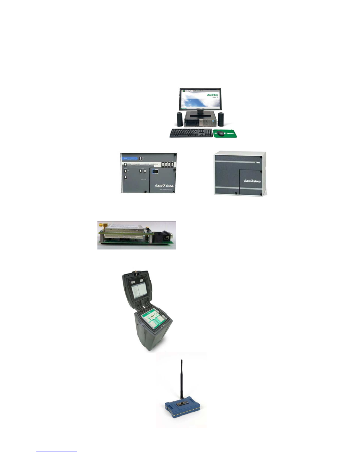
2. Components
Here are the main components needed for a Rain Bird® irrigation system with LINK900 wireless
communications:
Central Control computer:
Interface(s):
LINK900 radios:
PAR+ES (LINK) controllers:
Standalone Repeater (optional):
MAXI® Interface Module (MIM-LINK) or Two-Wire Interface (TWI-LINK)
September 2015
3
3. Radio Basics
LINK900 wireless communication works by broadcasting radio waves to communicate between the central
control and field controllers. The LINK900 system uses custom designed Frequency Hopping Spread
Spectrum radios (FHSS).
Key Advantages:
- No FCC license required for operation in USA.
- No antenna height restriction in most areas (check local regulations)
- Capability to use field controller radios as repeaters to relay the signal
- FHSS is highly resistant to narrowband interference
- FHSS is difficult to intercept
- FHSS can coexist in a frequency band with other broadcasts with minimal interference
Signal strength is measured in decibels (dB). Radios transmit with a certain amount of power (Wattage) and
signal reception is subject to loss of strength due to attenuation caused by impedance in the antenna
cables, fittings, and the atmosphere itself.
Radio transmission power is related to signal strength in the following manner:
- Reducing the output wattage by half reduces the signal strength by 3dB
- Doubling the output wattage increases the signal strength by 3dB
In Rain Bird® LINK900 wireless communications, no true electronic signal boost is provided after the radios.
Antennas can be used to shape or focus more of the transmitted signal energy into the areas targeted. This
signal increase is termed as “Gain”. An antenna with a “dB gain” value does not provide more power, but
rather it modifies the shape of the transmitted signal. The higher the antenna gain, the narrower the useful
signal beam width.
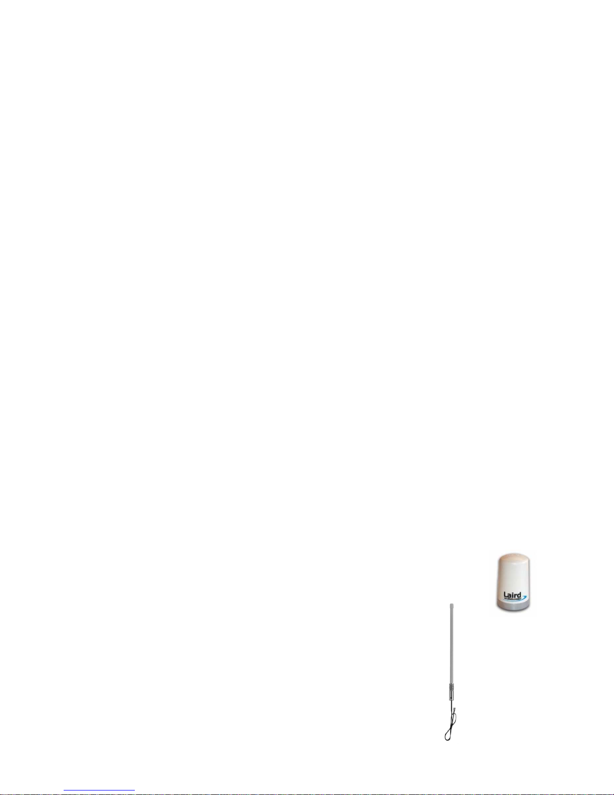
a)
Antennas:
Rain Bird® LINK900 wireless communications uses two distinct types of vertically polarized
antennas. Omnidirectional and Directional (also known as Yagi).
Omni-directional:
This is the most common antenna used. Each Rain Bird® Golf LINK900 radio/modem/antenna kit
(H49008 & H49004) comes with this type of antenna. Different types of Omni-directional
antennas can be used on a LINK900 system.
Here are two examples:
Standard PAR+ES Omni “shot glass style” antenna, 3dB (GSP-TRA9023N)
High Gain 48” Omni antenna, 5dB (GSP-ODA-48)
September 2015
4
b)
Directional Antenna (Yagi):
The Yagi antenna is typically used to focus the signal towards a single point and to minimize
interference to and from other radios.
Yagi Antenna, 6dB (GSP-YAGI-6)
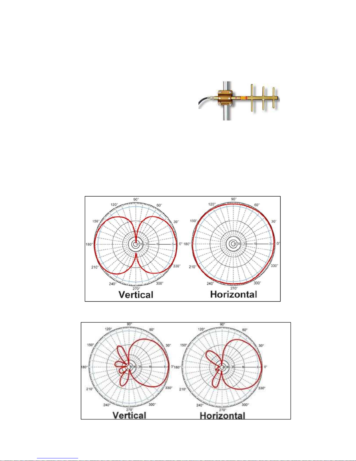
Antenna Field Patterns:
Each type of antenna has a defined field pattern. This indicates how the radio waves are
transmitted from and received by the antenna. The following are examples of two common types
of patterns; Omni-directional and Yagi.
Omni-directional Antenna Field Pattern (Typical)
Yagi Antenna Field Pattern (Typical)
September 2015
5
c)
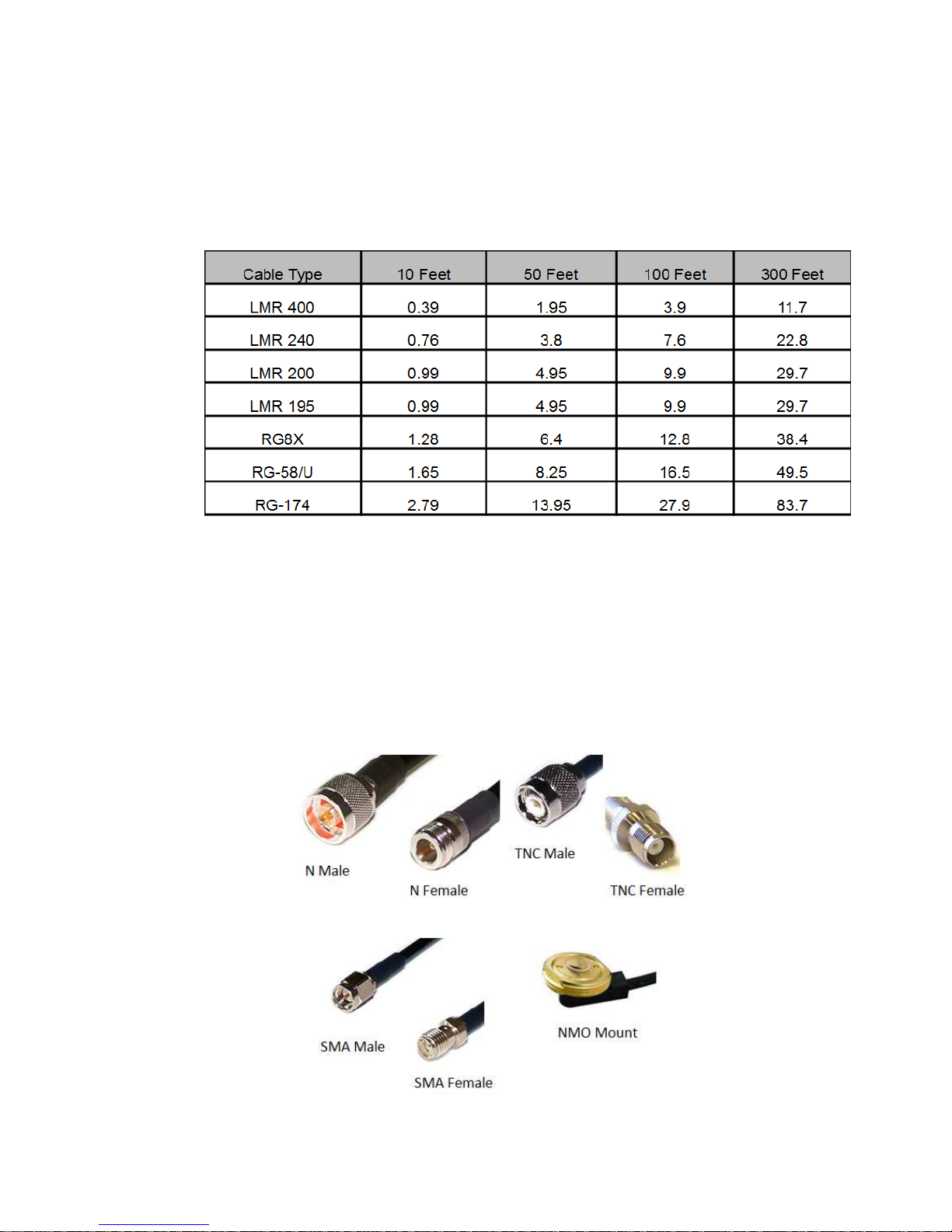
Antenna Cables:
Cable selection is very important as too much signal loss can affect the overall communication
performance. In general, lower loss cables tend to be larger in diameter and less flexible. LMR
type cables are more weather resistant than RG type cables, but RG type cables tend to be much
more flexible. Here is a table showing examples of signal loss in dB based on the type of cable:
Only 50 Ohm cable may be used with LINK900 systems. Please note that the frequency being
used will also affect the cable loss. Normally, higher frequencies have a higher loss potential.
This table is for the 900MHz range of frequencies.
d)
Antenna Cable Connectors
There are a wide variety of cable terminations available for 50 Ohm antenna cable. Four
different cable terminations are common in LINK900 systems: N, TNC, SMA and NMO. Other
terminations may also be encountered, especially if custom antennas or other devices are used.
September 2015
6
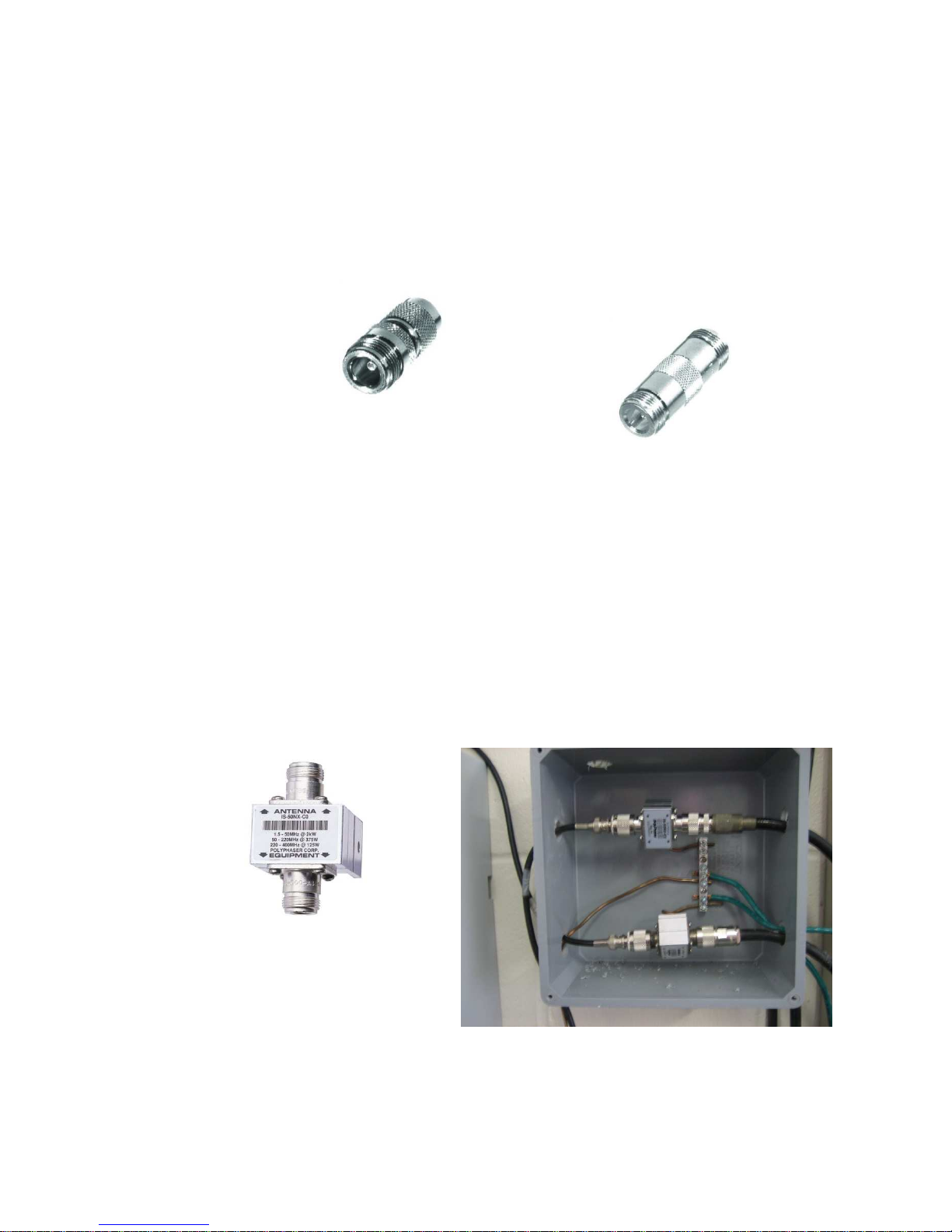
e)
Adapters:
In some cases, adapters may be required to accommodate the different antenna and cable
terminations used. However, the use of adapters should be minimized, as each adapter causes a
signal loss of ~0.25dB. Rain Bird recommends using cables made with the proper connector
types to minimize the use of adapters. The LINK900 radio is terminated with an SMA Female
connector and requires an SMA Male cable end connection. The Standalone Repeater is
terminated with a TNC Female connector and requires a TNC Male cable end connection. Here
are some adapter examples
e)
Surge Protection:
Surge protection should be used on all external antenna installations such as at the MIM-LINK /
TWI-LINK central control interface. There is no need for surge protection at a field controller
location if the standard antenna included in the Rain Bird® LINK900 radio/modem/antenna kits
(H49008 & H49004) is used. Where used, the surge protection MUST be rated for 900MHz
operation and MUST be grounded with a bare copper wire and a ground rod or plate. Rain Bird
recommends the Rain Bird® Polyphaser (HA1100) for surge protection of external antenna
installations in LINK900 systems.
Rain Bird® Polyphaser (HA1100)
N-Female by N-Female
Adapter, TNC Male to N-Female
Barrel Adapter, N-Female to N-Female
Two Polyphaser setup with proper grounding
September 2015
7
4. Component Setup
Proper installation of all components is key to having a robust system. This section will cover in detail all the
steps needed to properly setup LINK900 wireless communication for your Rain Bird® Golf irrigation system.
a)
MIM-LINK / TWI-LINK Interface Connection to Central Control
There are two options for connecting the central control interface (MIM-Link or TWI-Link) to the
central control computer: direct serial connection or via a MAXI
1. Direct Connect
For the direct connection when the interface is located near the central computer, just
connect the interface to the computer using the supplied cable.
®
Remote Location Kit.
b)
2. Connection via MAXI
When the interface is remotely located away from the central computer, a MAXI®
Remote Location Kit (p/n HA1000) is required.
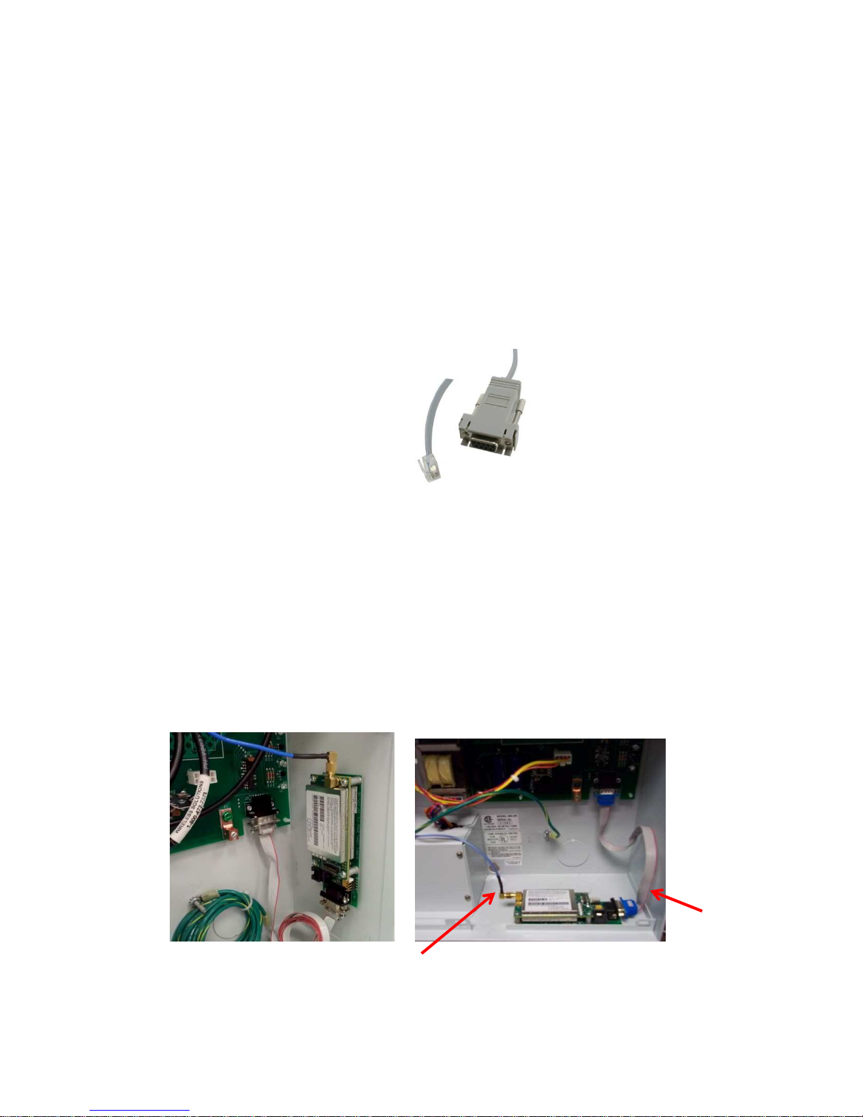
LINK900 radio for MIM-LINK / TWI-LINK Installation & Programming
To install the LINK900 radio/modem kit (H49001) in the MIM-LINK / TWI-LINK interface, only
two cables need to be connected. A 9-pin serial ribbon cable connects the LINK900 radio and the
Output Board located in the back of the interface. The second cable is the antenna cable (SMA
connector) which must be connected to an external antenna (not included in H49001).
Antenna cable
The pictures above show two different ways to mount the LINK900 radio inside the interface.
®
Remote Location Kit (MRLK)
Ribbon cable
September 2015
8
Programming:
The LINK900 radios supplied with H49001, H49004, and H49008 are identical and
interchangeable. However, the programming in them will vary depending on the function of the
radio. The LINK900 radio located at the MIM / TWI will always be programmed as the Master
(M) radio.
LINK900 radios are programmed using the GE MDS Element Manager application which runs on
Microsoft Windows OS computers. The software can be downloaded at this address:
https://www.gedigitalenergy.com/communications/MDS/software.asp?directory=Toolbox
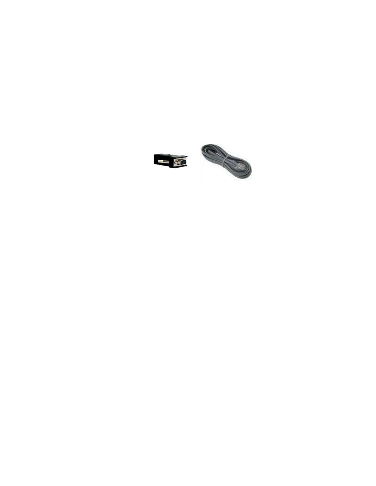
The programming cable (GSP-MDS-PRGCBL) is also needed, which is composed of a proprietary
cable and 9-Pin to RJ-11 adapter.
Connect the cable to the radio using the RJ-11 connector and connect the serial adapter to the
computer. Please note that if the computer does not have a serial port and a USB-to-Serial
adapter is used, the COM port used by the adapter must be selected in MDS Element Manager.
See Appendix section “7b” for help.
WARNING: Always ensure that an antenna is connected to the LINK900 radio before the radio
is powered-up, or damage to the radio may occur.
The LINK900 radio must be powered before a connection can be established. The radio receives
power from the MIM/TWI via the 9 pin ribbon cable. Programming the radio is completed via
the Configuration menu in the GE MDS Element Manager application.
Start the GE MDS Element Manager application. Confirm Device Type is set to TransNet. Under
Serial Connections, select the COM port that the programming cable is connected to. Confirm
the Settings (9600, 8, N, 1). To connect to the radio, select Connect Serial to begin
communicating with the LINK900 radio.
September 2015
9
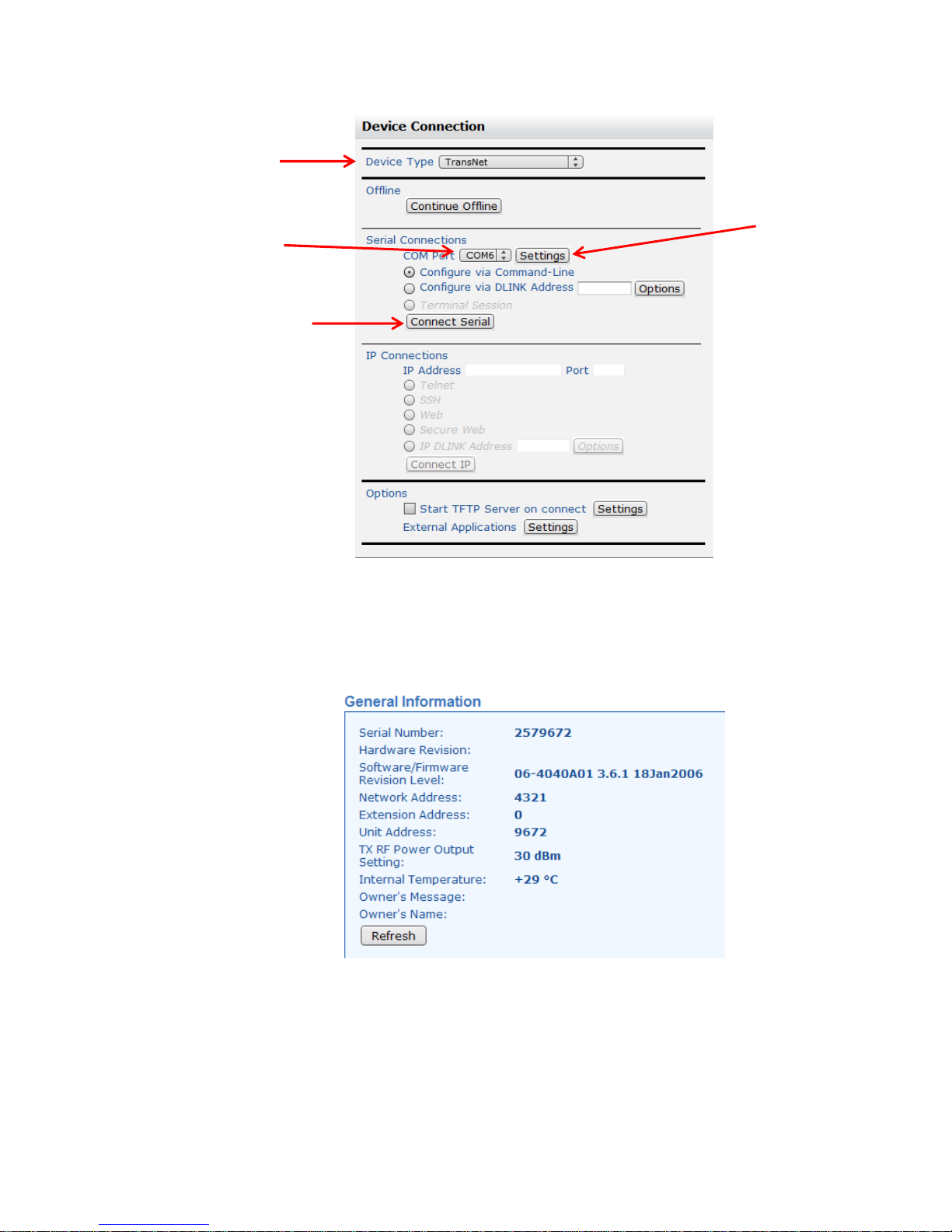
Device Type
COM Port
Connect to LINK900 Radio
Serial Settings
Upon successful connection to the LINK900 radio, the General Information will populate with the
radio’s Serial Number, Network Address, Firmware Revision Level and other details. This
information may be updated at any time by clicking on the Refresh icon.
September 2015
10
 Loading...