

Page 1
Troubleshooting
Decoders
Rain Bird® Decoders
Decoders are a cost-effective alternative to traditional in-field controllers.
Installed underground and featuring simple, low-cost wiring, decoders are
an aesthetically pleasing and economical option for reliable, in-field control.
Installation requires up to 80 percent less wire than conventional controller
systems. Electronic components are completely encapsulated to protect
against the elements. And system expansion is easy: simply splice into the
communication line to add additional decoders.
Learn more about this simple, reliable technology and how to service it in
the following topics:
• General Information
• No Control Over Field Decoders
• Shorted Wire Path
• Suspected Broken Wire Path
• Suspected Ground Fault
1
Page 2

Troubleshooting
Decoders
General Information
Calculate expected “At Rest” current
draw on each wire path and each
LDI or SDI interface.
• FD-101 = 0.5 mA
• FD-102 = 0.5 mA
• FD-202 = 1.0 mA
• FD-401 = 1.0 mA
• FD-601 = 1.0 mA
Prior to troubleshooting when using
a clamp meter, make sure you know
the static current draw of the wire
path or sections of wire path you will
be troubleshooting. (1) To calculate
the static current draw at an individual
wire path section, add the number of
decoders that are downstream from the
test point, and multiply it by the current
draw of each decoder to determine
the total calculated current draw of
the wire section after the test point. (2)
To calculate the static current draw of
an entire wire path, add the number
of decoders on the entire wire path,
and multiply it by the current draw of
each decoder to determine the total
calculated current draw of the wire path.
(3) To calculate the static current draw of
an entire interface, add up all calculated
wire path current draws that are
connected to the interface.
Example:
BLUE WIRE
• 100 FD-101 x 0.5 mA = 50 mA
• 25 FD-202 x 1.0 mA = 25 mA
• 10 FD-401 and FD-601 = 10 mA
• Total Blue Wire current = 85 mA
RED WIRE
• 80 FD-102 x 0.5 mA = 40 mA
• 20 FD-202 x 1.0 mA = 20 mA
• 15 FD-401 and FD-601 = 15 mA
• Total Red Wire current = 75 mA
• Total Current for LDI or SDI = 85 +
75 = 160 mA
Tool List
• Spare Decoders
• Clamp Meter (current specifications are
available by calling 1-866-GSP-XPRT)
• Digital Multi-Meter
• Direct Bury Wire Splice Kits
• Maxi Wire Strippers
• Wire Strippers
• Linesman Pliers
• Extra Maxi Wire
• Updated “As-Built” drawing (“As Built”
should show wire path colors, decoder locations,
expected current draw per wire path and expected
current draw per LDI/SDI.)
NOTE: If the wire path has been looped,
you must break the loop in order to
properly troubleshoot current draw
using a clampmeter.
(see Locating A Bad Decoder on page 4).
2
Page 3
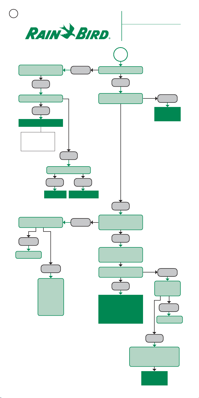
STAR T
Recommended Rain Bird®
Troubleshooting Procedure for
“No Control Over
Field Decoders”
Symptoms: No control over field
decoders and zeros in course log.
Check switch and incoming
power at 120VAC.
OKAY
Check incoming 24VAC.
OKAY
Replace LDI/SDI
If replacing transformer,
connec t 24VAC wires to
termin al screws be fore
plugging transformer in.
Replace Fu se Replace Transformer
OFF
BAD
Check Transformer Fuse
BLOWN GOOD
Verif y Power LED is on
OKAY
Confirm Sy stem Status is O K
in centr al control so ftware.
OKAY
BAD
Troublesh oot as
Necessary
Turn off wire p ath
slide sw itch and cyc le power.
SOLID LED
Replace L DI or SDI
Turn on one fie ld
wire pat h at a
time to fin d wire
path wit h short
condition. LED
will be so lid when
short ed wire path
OKAY
is activated.
SOLID LED
Check fie ld LED for
alternating GREEN/RED colors
every 0.5 seconds.
OKAY
Start 50/6 0Hz test in Dec oder
Diagnostic section of central
control software.
Verif y output volt age on each
wire pat h is 33± VAC.
OKAY
Run ON/OFF Test in D ecoder
Diagnostic Section of
Central Co ntrol Soft ware
and Proce ed to Field
Troubleshooting
expec ted and act ual “at rest ” current
draw in De coder Diagn ostic sec tion of
LOW
Disconnect
field wires and
recheck voltage.
LOW
Replace LDI/SDI
OKAY
Reconn ect field wir e. Compare
central control software.
Procee d to Field
Troubleshooting
3
Page 4

Troubleshooting
VOLT METER
Decoders
INSTALLATION DETAILS LARGE AND SMALL DECODER INTERFACE
Use one or t wo screws at t he top and one at t he
bottom, depending on support.
CAU TION
Mains- and s ystem-groun d are
not internally connected and must
be separa ted to provide the be st
protection against surges.
On when po wer is on. LED is co ntrolled by
proces sor. Will not tu rn on if no firmw are is
downlo aded. Blink s when there i s an error
condition (see below).
ON OFF
24V-AC MAINS
@2A GND
SENS-1
SENS-2
EARTH
POWER/ERROR
PC -> DATA
DATA->PC
LINE
1A-1B 2A-2B 3A-3B4A-4B
OFF
ON
PC-COM
Normal ly off. Blinks wh en data is received from PC.
Normal ly off. Blinks wh en data is sent to PC.
Line ind icator, toggl es betwee n red and green w ith
line volt age polari ty.
Switche s for discon nection o f line with pro blem.
Field wi res. Up to four t wo-wire p aths may be
connected.
Serial c able, 9 PIN-9 PI N for PC commun ication.
Connec t to 24 VAC
transformer
To System Gro und
SENSOR 1 (e.g. R ain Sensor)
SENSOR 2 (No t Shown) (e.g. Alarm S ensor)
During p ower up, the LED ’s will blink in se quence endi ng with POWER L ED on for 5 secon ds.
If the POWE R LED blinks, i t means that an err or is d etected b y the unit. The r eason for th e error is ind icated by the o ther LED’s:
• If D ATA-> PC is ON = line volt age has been s witched off b ecause con nection t o the PC is lost .
• If LINE is ON = lin e voltage is be low 25 V (shor t).
LOCATING A BAD DECODER USING A CLAMP METER
• In the D ecoder Dia gnostic s screen sel ect 60Hz te st mode to all ow the clamp me ter to measure c urrent. Wh en done with
troubl eshootin g remember to c ancel the 60 Hz test mode to r esume irr igation.
CAM
HIGHER THAN
CALCULATED
VALUE
33v±
CLAMP METER
0.5±
HIGHER THAN
0.5±
1.0±
CALCULATED VALUE
HIGHER THAN
CALCULATED VALUE
BAD
DECODER
HIGHER THAN
CALCULATED VALUE
LESS THAN CALCULATED VALUE
HIGHER THAN
CALCULATED VALUE
LESS THAN
33 VOLTS ± WHEN IN 60Hz TEST MODE
CALCULATED VALUE
4
Page 5

STAR T
Recommended Rain Bird®
Troubleshooting Procedure for
“Shorted Wire Path”
Symptoms: No Decoder
Operation on Wire Path or LDI.
Field LED may be solid or faint.
Go To Troubleshooting Card:
“No Contro l Over
Field Decoders”
Replace MSP-1
DOWNS TREAM
LESS THAN
UPSTREAM
Use clam pmeter to che ck RED
and BLACK w ires on upst ream
or “EQUIP ” end of MSP-1.
UPSTREAM
EQUAL TO
DOWNSTREAM
Break c ritical pat h wire loop
(if present). Choose point
half way out on wire p ath.
Using cl amp meter, chec k RED
and BLACK wires individually.
Compar e each value to
expected current draw.
HIGH
Choose point halfway
between measurement point
and end of w ire path.
NOT NORMAL
HIGH “AT REST ”
CURRE NT DRAW
MEASURED
LOW/ZERO
Turn off all LDI fi eld wire pat h
slide sw itches and co nfirm
normal LDI operation.
OKAY
Open Decoder Diagnostics
window i n central
control software.
Turn on wir e path slide sw itches
one at a tim e. Monitor cur rent to
verif y it reaches e xpected
“at rest ” draw for wir e path.
Choose point halfway back
to centr al control an d
measure current draw.
Repeat to n arrow down
locati on of wire pat h short.
SHORT
FOUND
Confirm b y using
clampm eter on singl e BLUE
communication wire.
CONFIRMED
OKAY
Turn Off Field W ire Path
Slide Switch — Repeat
for Each Additional
Wire Path
Short c ould be caus ed
by conta ct betwee n
RED and BL ACK
conductors or internal
to a decod er or LSP-1.
Single Address
Decoder = 0.5mA
Multi-Address
Decode r = 1.0 mA
LSP-1 = 0.0 mA
Run ON/OFF Test in D ecoder
Diagno stics to Validate
System Operation
NOT EQUAL
Repair or replace components
as necessary.
COMPLETE
Compar e “at rest” cu rrent to
expected “at rest” current.
EQUAL
No Further Action
5
Page 6

STAR T
Recommended Rain Bird®
Troubleshooting Procedure for
“Suspected Broken
Wire Path”
Symptoms: Zeros in course log.
No response on parts of wire path
or partial connection (Bad Splice).
Compar e stations a nd areas that
pass wit h stations a nd areas that
do not pas s ON/OFF test.
LOW
Good “As Buil t”
Open Decoder Diagnostics
in centr al control so ftware.
Compar e actual “at re st” curr ent
draw to ex pected cu rrent draw.
LOW
No “As Built ”
Turn off all LDI fi eld output w ire
path slide switches.
Turn on firs t wire path. Co mpare
expec ted actua l “at rest” cu rrent
draw to ex pected cu rrent draw
in Decoder Diagnostic window in
central control software.
LOW
Run ON/OFF t est in Decode r
Diagnostic window of central
contro l softwa re to locate
last passing decoder and first
failing decoder.
GO TO FIEL D
Activate 50/60Hz mode.
Use clam pmeter to find
broken wire.
NORMAL
Problem Unlikely a
Broken Wi re Path
NORMAL
Repeat for each
wire path
NORMAL
Problem Unlikely a
Broken Wi re Path
CURRENT = 0
Break is b etween
centra l control and
measurement point.
Break c ritical pat h wire loop (if
present). Choose point halfway out
on wire p ath. Using cla mpmeter,
check RE D and BLACK wire s
individually. Compare each value
to expe cted curr ent draw.
Repeat to determine exact
locati on of broken w ire or parti al
connection (Bad Splice).
LOW
Break is b etween
measurement point
and end of w ire path.
6
Page 7

Severity of Ground Fault
can var y based on so il
moisture content.
“Suspected Ground Fault”
STAR T
Visual ly check Fiel d LED on
LDI/SDI fo r clean alter ation
from RED t o GREEN at
0.5 second intervals.
NOT CLEAN
Recommended Rain Bird®
Troubleshooting Procedure for
(Leakage to Ground)
Symptoms: Lower run times or zeros
in the course log. Fluctuating current
reported in Decoder Diagnostics. No
clean alternating color in
Field LED on LDI/SDI.
Replace LDI
NOT CLEAN
Turn off LDI wi re path slide
switch es. Cycle LDI Power Sw itch
from OFF t o ON.
CLEAN
Turn on each w ire path one at a
time. Af ter 10 seconds, v erify no
“Flicke r” on Field LED.
FLICKER
If visib le on Field LED, ope n
Decoder Diagnostics window in
central control software.
Verif y “at rest” cu rrent draw.
HIGH
Activate 50/60Hz mode test.
Using a cl ampmeter, at the
downstream (field) side of the
MSP-1, compare the m A draw
of RED and BL ACK wires.
If Wire Path i s
Activated, Consider
Possibility of Ground
Fault on Path
Normal s ystems sho uld
expec t “at rest” c urrent
draw to fluc tuate
betwe en 2 mA – 5 mA.
Choose point halfway
between measurement point
and central control. Retest.
Repeat t his method to n arrow
down loc ation of dama ged
insula tion and leak age to
ground. Repair as necessary.
When rep airs are com plete,
verif y “at rest” cu rrent draw
matches expected current draw.
Run ON/OFF t est to validat e
system operation.
DRAW CL OSE
TO ZERO
VALIDATED
The wire w ith the highe r
draw will have leakage.
At LDI, disc onnect wi re with lower
draw and c hoose point h alfway
to end of wi re path. Meas ure
draw in co nnected (ac tive) wire.
Disconnect any critical path loops
before testing.
DRAW GREATER
THAN ZERO
Choose point halfway
between measurement point
and end of w ire path. Rete st.
No Further Action.
7
Page 8

The Intelligent Use of Water.
Leadership • education • partnerships • produc ts
™
At Rain Bird, we believe it is our
responsibility to develop products and
technologies that use water efficiently.
Our commitment also extends to
education, training and services for our
industry and our communities.
The need to conserve water has never
been greater. We want to do even
more, and with your help, we can. Visit
www.rainbird.com for more information
about The Intelligent Use of Water.
™
Rain Bird Corporation
6991 East Southpoint Road
Tucson, AZ 85756, U.S.A.
Phone: (800) 984-2255; (520) 741-6100
Fax: (520) 741-6522
Email: rbgolf@rainbird.com
Technical Service and Support
(800) RAINBIRD (U.S. and Canada only)
The Intel ligent Use of Water™ — Vis it www.rainbi rd.com to learn abo ut our efforts .
Registered trademark of Rain Bird Corporation
®
© 2012 Rain Bird Corpo ration 2/12
Rain Bird International, Inc.
1000 West Sierra Madre Ave
Azusa, CA 91702 U.S.A.
Phone: (626) 963-9311
Fax: (626) 852-7343
www.rainbird.com
8
D3745 6
 Loading...