

Page 1
Rain+Birdt
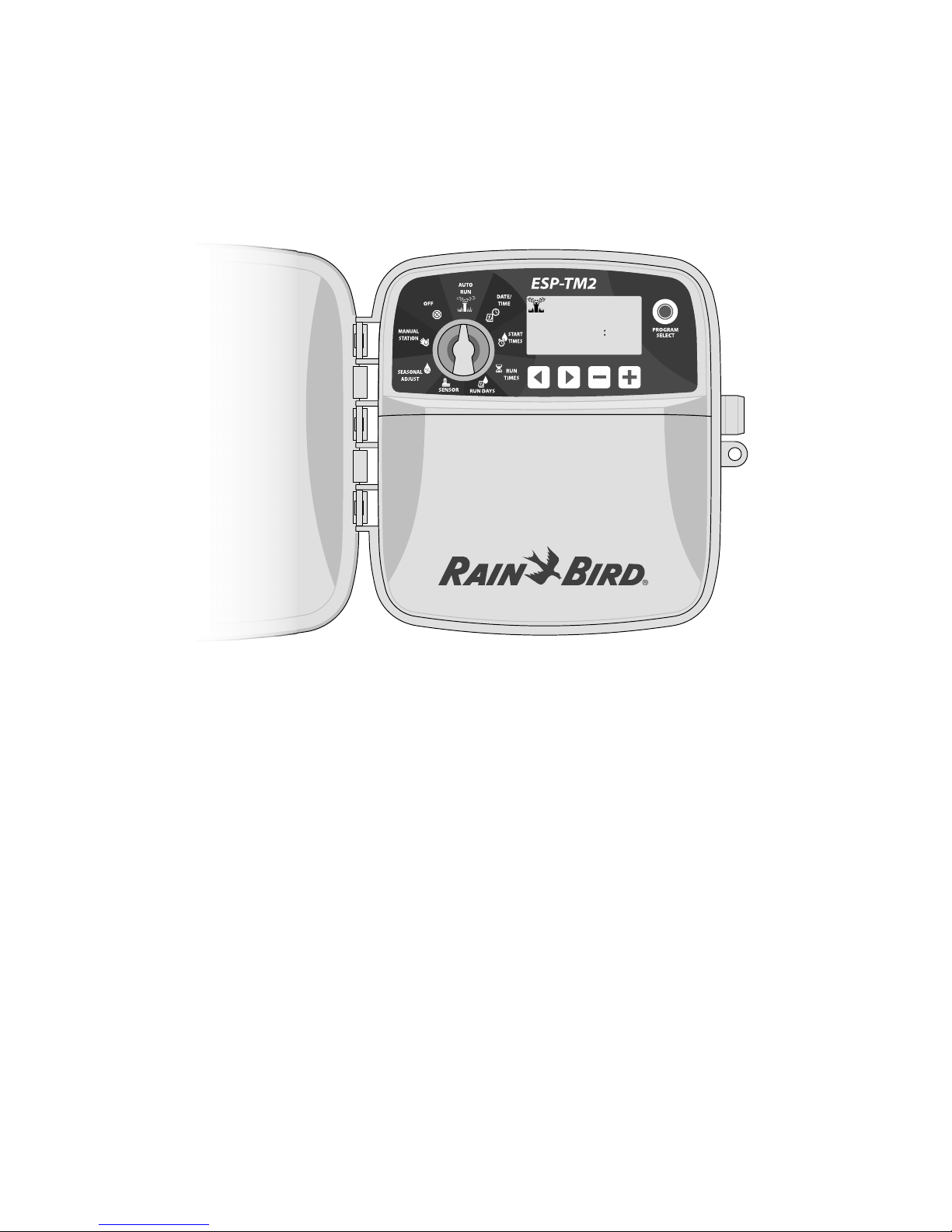
ESP-TM2 Controller User Manual
MINUTESHOURSTATION
10220
REMAINING
RUN TIME
Introduction .........................................2
Welcome to Rain Bird ............................................. 2
Controller Features ................................................. 2
Installation ........................................... 2
Mount Controller ..................................................... 2
Wiring Connections ................................................ 3
Connect Valves ...................................................................3
Connect Master Valve (optional) ..................................3
Connect Pump Start Relay (optional) .........................3
Connect Rain/Freeze Sensor (optional) .....................4
Connect Custom Wiring (optional) .............................4
Controls and Indicators ........................ 5
Special Features ................................... 5
Basic Programming .............................. 6
1. Set Date and Time ............................................6
2. Set Watering Start Times ................................6
3. Set Station Run Times ..................................... 6
4. Set Watering Days ............................................6
Custom Days of the Week ...............................................6
Manual Watering Options ....................7
Test All Stations........................................................ 7
Run a Single Station ............................................... 7
Run a Single Program .............................................7
Normal Operation ................................ 7
AUTO RUN ................................................................. 7
OFF .............................................................................. 7
Advanced Programming ......................8
Odd or Even Calendar Days .................................. 8
Cyclic Days ................................................................8
Rain Sensor ............................................................... 8
Seasonal Adjust ....................................................... 8
Delay Watering .........................................................8
Permanent Days Off................................................9
Options ................................................ 9
Reset Button ............................................................. 9
Remote Accessories ................................................ 9
Troubleshooting ................................. 10
Watering Issues ......................................................10
Electrical Issues ...................................................... 10
Page 2
Introduction
CONNECT
120 VAC
RESET
ACCESSORY
12345678
24VAC SENS
CM
9101112
Installation
Welcome to Rain Bird
Thank you for choosing Rain Bird’s ESP-TM2 controller. In this
manual are step by step instructions for how to install and
operate the ESP-TM2.
MINUTESHOURSTATION
10220
REMAINING
RUNTIME
Controller Features
Feature Description
Maximum Stations 12
Simultaneous Stations 1 plus master valve
Start Times 4
Programs 3
Program Cycles Custom Days, Odd, Even
and Cyclic
Permanent Days O Per program
Master Valve Control On/O per station
Rain Delay Supported
Rain/Freeze Sensor Supported
Rain Sensor Control Global or by station
Seasonal Adjust Global or by program
Manual Station Run Yes
Manual Program Run Yes
Manual Test All Stations Yes
Station Advance Yes
Short Detect Yes
Delay Between Stations Yes
Accessory Port Yes (5 pin)
Save & Restore Programming Yes
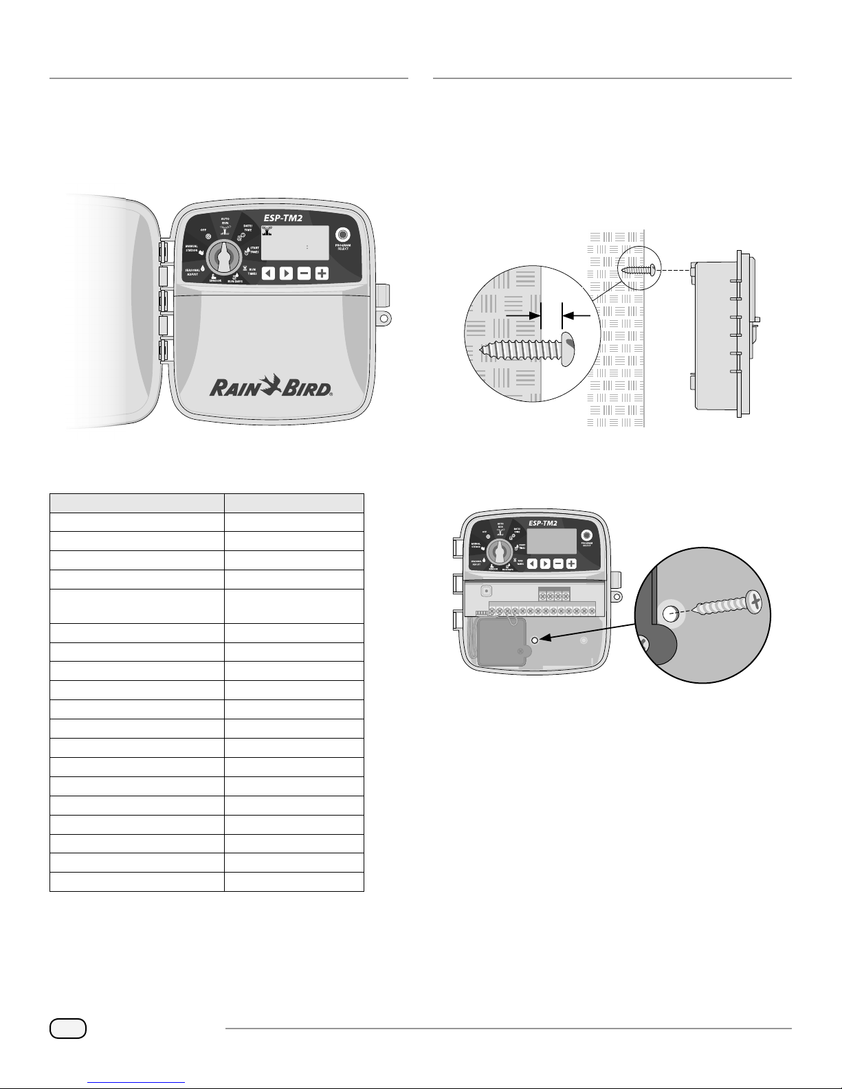
Mount Controller
Drive a mounting screw into the wall, leaving an 1/8 inch
A
gap between the screw head and the wall surface (use the
supplied wall anchors if necessary), as shown.
Locate the keyhole slot on back of the controller unit and
B
hang it securely on the mounting screw.
1
1/8 IN.
1/8 IN.
Remove the wiring bay cover on the lower part of the
C
2
controller unit, and drive a second screw through the open
hole inside the controller and into the wall, as shown.
3
NOTE: Choose a suitable mounting location close to a
120 VAC wall outlet.
2
ESP-TM2 Controller
Page 3
Wiring Connections
CONNECT
120 VAC
RESET
ACCESSORY
12345678
24VAC SENS
CM
9101112
CONNECT
120 VAC
RESET
ACCESSORY
12345678
24VAC SENS
CM
9101112
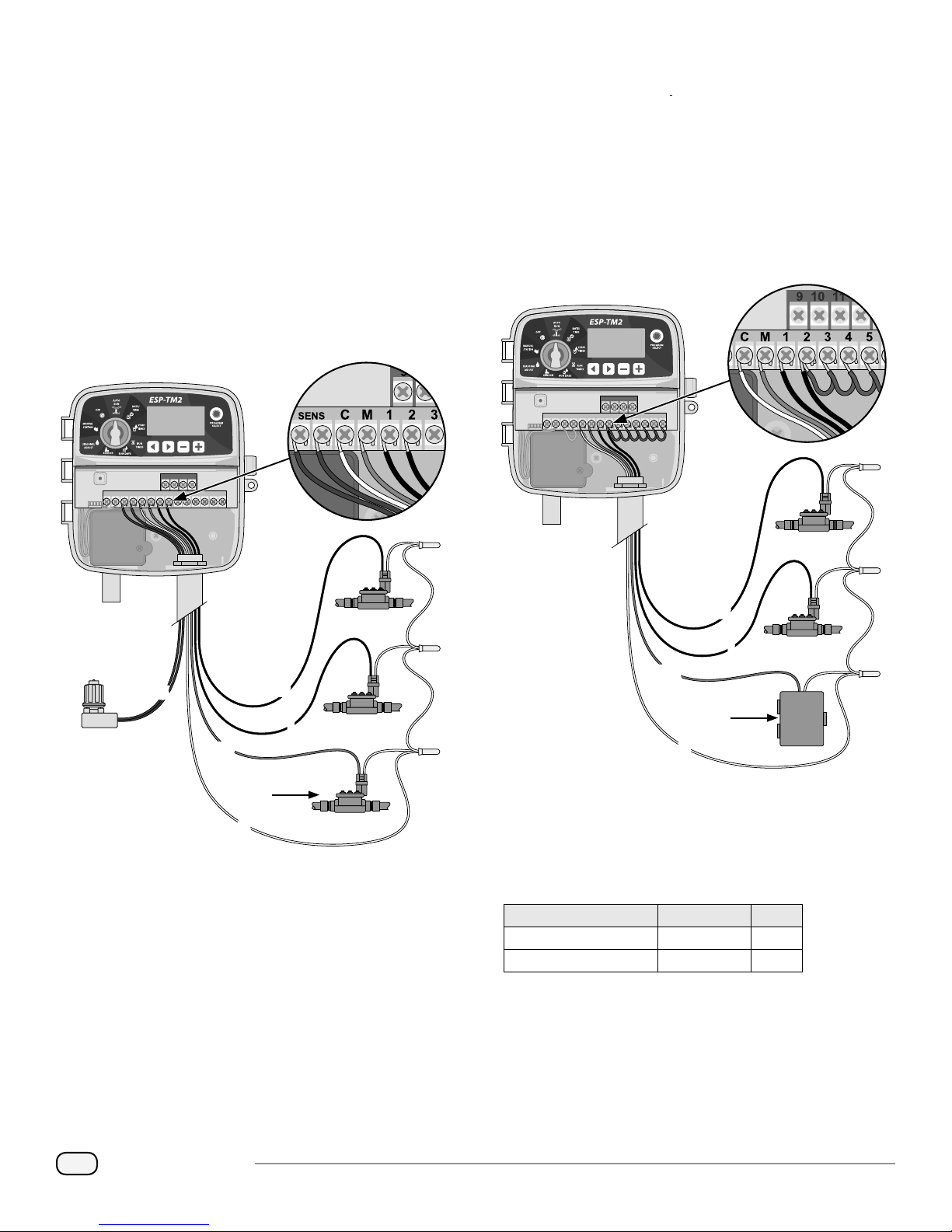
Connect Valves
Route all eld wires through the opening at the bottom
A
of the unit, or through the knock-out in back of the unit.
Attach conduit if desired, as shown.
Connect one wire from each valve to one of the numbered
B
station terminals (1-12) on the controller, as shown.
Connect a eld common wire (C) to the common terminal
C
(C) on the controller. Then connect the remaining wire
from each valve to the eld common wire, as shown.
Connect Pump Start Relay (optional)
The ESP-TM2 can control a pump start relay, to turn the
pump on and off as needed.
Connect a wire from the pump start relay (PSR) to the
A
master valve terminal (M) on the controller. Then connect
another wire from the pump start relay to the eld
common wire, as shown.
To avoid the possibility of damage to the pump, connect
B
a short jumper wire from any unused terminal(s) to the
nearest terminal in use, as shown.
NOTE: The ESP-TM2 controller supports one valve
solenoid per station terminal.
1
S
MV
MASTER
VALVE
C
Connect Master Valve (optional)
D
Connect a wire from the master valve (M) to the master
valve terminal (M) on the controller. Then connect the
remaining wire from the master valve to the eld common
wire, as shown.
2
2
1
4
3
2
NOTE:
Connection
to pump
and external
power not
PSR
shown. Refer
to pump
installation
instructions.
NOTE: The ESP-TM2 controller DOES NOT provide
power for a pump. The relay must be wired according to
manufacturer instructions.
Only the following Rain Bird pump start relay models are
compatible with the ESP-TM2:
Description Model # Volts
Universal Pump Relay PSR110IC 110V
Universal Pump Relay PSR220IC 220V
2
1
PUMP START
RELAY
C
1
3
ESP-TM2 Controller
Page 4
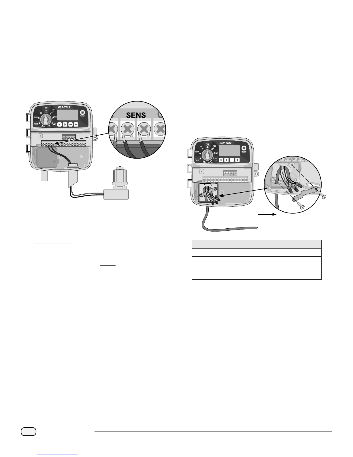
Connect Rain/Freeze Sensor (optional)
CONNECT
120 VAC
RESET
ACCESSORY
12345678
24VAC SENS
CM
9101112
The ESP-TM2 controller can be set to obey or ignore a rain
sensor.
Refer to the Rain Sensor section under Advanced
Programming.
Connect Custom Wiring (optional)
If desired, the provided 120 volt power cord can be
removed and replaced with a custom wiring.
To remove the factory installed power cord and connect
custom wiring:
Remove the yellow jumper wire from the SENS terminals
A
on the controller.
Connect both rain sensor wires to the SENS terminals, as
B
shown.
2
NOTE: Do not remove the yellow jumper wire unless
connecting a rain sensor.
Ensure that AC power is disconnected.
A
Remove the controller junction box cover and disconnect
B
the power cord to the unit.
Remove the factory installed power cord by loosening the
C
2 screws securing the metal strain-relief bar, as shown.
Connect the external power supply wires using the wire
D
nuts and then re-secure the metal strain relief bar by
tightening the 2 screws.
4
RESET
ACCESSORY
24VAC SENS
9101112
12345678
CM
TO EXTERNAL
POWER SUPPLY
NOTE: Rain Bird controllers are only compatible with
normally closed rain sensors.
NOTE: For wireless rain/freeze sensors, refer to
installation instructions for sensor.
WARNING: Do not apply power until you have
completed and checked all wiring connections.
Power Wiring Connections (120VAC)
Black supply wire (hot) to the black transformer wire
White supply wire (neutral) to the white transformer wire
Green supply wire (ground) to the green or green-yellow
transformer wire
Verify that all wiring connections are secure and then
E
replace the junction box cover.
CAUTION: The strain-relief bar must be re-secured for
the unit to function properly.
WARNING: DO NOT apply power until you have
completed and checked all wiring connections.
4
ESP-TM2 Controller
Page 5

Controls and Indicators
Turn the dial to select programming features.
OFF
Disables automatic
irrigation.
MANUAL STATION
Start watering
any or all stations
immediately.
SEASONAL ADJUST
Adjust Run Times
from 5% up to 200%.
SENSOR
Set controller to obey or
ignore a rain sensor.
AUTO RUN
Watering occurs
automatically.
RUN DAYS
Set watering day
options for each
program.
DATE/TIME
Set the current
Date and Time.
RUN TIMES
Set Run Times for
each program.
START TIMES
Set up to 4 Start
Times per program.
PROGRAM
SELECT BUTTON
Select Program A,
B or C.
– / + BUTTONS
Adjust program
settings.
BACK/NEXT
BUTTONS
Select
programming
options.
Special Features
Turn the dial to the desired position.
Press and hold
SET INTERSTATION
DELAY
A station delay (from 1
second to 9 hours) ensures
that a valve has completely
closed before the next one
opens.
RESET TO FACTORY
DEFAULTS
All programmed schedules
will be erased.
SET RAIN SENSOR BYPASS
BY STATION
Tells a station to obey or
ignore a rain sensor.
and at the same time.
SAVE
PROGRAMMING
RESTORE
PROGRAMMING
SET MASTER VALVE
BY STATION
Allows a station to be
controlled by a master
valve or pump start
relay.
SET TO ODD, EVEN OR
CYCLIC WATERING
See Advanced Programming.
5
ESP-TM2 Controller
Page 6

Basic Programming
Set Date and Time
1
Turn the dial to DATE/TIME.
Press
Press
Press and hold
To change the time format (12 hour or 24 hour):
With MINUTES blinking, press
Press
then press to return to the time setting.
2
Up to four Start Times are available for each program.
Press Program Select to choose the desired Program (if
necessary).
Press
Press
AM/PM setting is correct).
Press
or to select the setting to change.
or to change the setting value.
or + to accelerate adjustments.
-
.
or to select the desired time format,
Set Watering Start Times
Turn the dial to START TIMES.
or to select an available Start Time.
or to set the selected Start Time (ensure the
to set additional Start Times.
Set Watering Days
4
Custom Days of the Week
Set watering to occur on specific days of the week.
Turn the dial to RUN DAYS.
Press Program Select to choose the desired Program (if
necessary).
Press
ON or OFF, and to automatically move to the next day.
You can press
the previous or next day.
or to set the selected (blinking) day as either
or at any time to move the cursor to
CAUTION: If Sunday is selected, will enter and
activate Cyclic Watering (see the Advanced Programming
section). If this is not desired, press the button to
return to watering by Custom Days.
Set Station Run Times
3
Run Times can be set from one minute up to six hours.
Turn the dial to RUN TIMES.
Press Program Select to choose the desired Program (if
necessary).
Press
Press
Press
or to select a Station.
or to set the Run Time for the selected Station.
to set additional Station Run Times.
6
ESP-TM2 Controller
Page 7

Manual Watering Options
Normal Operation
Test All Stations
Start watering immediately for all programmed stations.
Turn the dial to MANUAL STATION.
Press
Press and hold
manual station test.
or to set a Run Time.
or turn the dial to AUTO RUN to start
Run a Single Station
Start watering immediately for a single station.
Turn the dial to MANUAL STATION.
Press
Press
Press
Press and hold
selected Station.
to display the MANUAL STATION screen.
or to select a Station.
or to set a Run Time.
or turn the dial to AUTO RUN to start the
Run a Single Program
Start watering immediately for one program.
AUTO RUN
During watering, the display shows a blinking sprinkler
symbol, the current Program and the Remaining Run Time.
OFF
Turn the dial to OFF to stop automatic irrigation or to
cancel all active watering immediately.
CAUTION: Watering will NOT occur if the controller
remains in OFF.
Turn the dial to AUTO RUN.
Press Program Select to choose the desired Program (if
necessary).
Press and hold
During Manual Watering:
The display shows a blinking sprinkler symbol, the active
Station Number or Program, and the Remaining Run Time.
To cancel manual watering, turn the dial to OFF for three
seconds until the screen shows OFF.
to start the selected Program.
7
ESP-TM2 Controller
Page 8

Advanced Programming
Odd or Even Calendar Days
Set watering to occur on all ODD or EVEN calendar days.
Turn the dial to RUN DAYS.
Press Program Select to choose the desired Program (if
necessary).
Press and hold
EVEN is displayed.
and at the same time until ODD or
Cyclic Days
Set watering to occur at specific intervals, such as every 2
days, or every 3 days, etc.
Turn the dial to RUN DAYS.
Press Program Select to choose the desired Program (if
necessary).
On the Custom Days screen, press
screen is displayed (after SUN).
Press
Press
begins. The NEXT watering day updates on the display to
indicate the day that watering will start as shown.
or to set the desired DAY CYCLE, then press
or to set the DAYS REMAINING before the cycle
until the Cyclic
Seasonal Adjust
Increase or decrease program run times by a selected
percentage (5% to 200%).
Example: If the Seasonal Adjust is set to 100% and the station
Run Time is programmed for 10 minutes, the station will run
for 10 minutes. If the Seasonal Adjust is set to 50%, the station
will run for 5 minutes.
Turn the dial to SEASONAL ADJUST.
Press
percentage setting.
To adjust an individual Program, press Program Select to
choose the desired Program (if necessary).
or to increase or decrease the global
Delay Watering
Suspend watering for up to 14 days.
Turn the dial to AUTO RUN, then press and
hold
Press
watering day will update on the display to indicate when
watering will resume.
or to set the DAYS REMAINING. The next
Rain Sensor
Set the controller to obey or ignore a rain sensor.
When set to ACTIVE, automatic irrigation will be suspended
if rainfall is detected. When set to BYPASS all programs will
ignore the rain sensor.
Turn the dial to SENSOR.
Press
8
or to select ACTIVE (obey) or BYPASS (ignore).
NOTE: See Special Features to set Rain Sensor Bypass
by Station.
ESP-TM2 Controller
To cancel a Rain Delay, set the DAYS REMAINING back to 0.
NOTE: When the delay expires, automatic irrigation
resumes as scheduled.
Page 9

Permanent Days Off
CONNECT
120 VAC
RESET
ACCESSORY
12345678
24VAC SENS
CM
9101112
CONNECT
120 VAC
RESET
ACCESSORY
12345678
24VAC SENS
CM
9101112
Prevent watering on selected days of the week (for Odd,
Even or Cyclic programming only).
Turn the dial to RUN DAYS.
Press Program Select to choose the desired Program (if
necessary).
Press and hold Program Select.
Press
Day O or press to leave the day ON.
to set the selected (blinking) day as a Permanent
Options
Reset Button
If the controller is not working properly, you can try
pressing RESET.
Insert a small tool such as a paper clip, into the access
hole and press until the controller is reset. All previously
programmed watering schedules will remain stored in
memory.
Remote Accessories
A 5 pin accessory port is available for Rain Bird approved
external devices.
9
ESP-TM2 Controller
Page 10

Troubleshooting
Watering Issues
Problem Possible Cause Possible Solution
Watering icon on the
display is flashing, but
the system is not watering
Automatic and/or Manual
Watering will not start
Excessive watering Programs may have multiple start times
Electrical Issues
Problem Possible Cause Possible Solution
Display is blank. Power not reaching the controller. Verify the main AC power supply is securely plugged in or connected and working properly.
Display is frozen and
controller will not accept
programming.
Water supply issue. Verify there is no disruption to the main water line and that all other water supply lines are
Wiring is loose, not properly connected
or damaged.
Connected rain sensor may be activated. Let the rain sensor dry out or else disconnect it from the controller terminal block and replace it
Jumper wire connecting the two SENS
terminals may be missing or damaged.
Solenoid or master valve is shorted. Confirm short message on the display. Correct the issue in the wiring. Clear the message by
that were set unintentionally
An electrical surge may have interfered
with the controller’s electronics.
open and functioning.
Check that wiring is securely connected at the controller and in the field. Check for damage and
replace if necessary. Check wiring connections and replace with watertight splice connectors if
needed.
with a jumper wire connecting the two SENS terminals.
Jumper the two SENS terminals on the controller terminal block by connecting them with a
short length of 14 to 18 gauge wire.
testing watering at the shorted valve or by pressing the button.
Programs (A, B or C) only require a single start time in order to run. Separate start times are not
required for each valve.
Verify the orange power supply wires are connected to the controller “24 VAC” terminals.
Unplug the controller for 2 minutes, then plug it back in. If there is no permanent damage, the
controller should accept programming and resume normal operation.
Press and release the RESET button.
Safety Information
WARNING: This appliance is not intended for use by persons
(including children) with reduced physical, sensory or mental
capacity, or lack of experience and knowledge unless they
have been given supervision or instruction concerning use of
the appliance by a person responsible for their safety. Children
should be supervised to ensure that they do not play with the
appliance.
WARNING: Special precautions must be taken when valve
wires (also known as station or solenoid wires) are located
adjacent to, or share a conduit with other wires, such as those
used for landscape lighting, other “low voltage” systems or
other “high voltage” power.
Separate and insulate all conductors carefully, taking care not
to damage wire insulation during installation. An electrical
“short” (contact) between the valve wires and another power
source can damage the controller and create a re hazard.
WARNING: All electrical connections and wiring runs must
comply with local building codes. Some local codes require that
only a licensed or certied electrician can install power. Only
professional personnel should install the controller. Check your
local building codes for guidance.
CAUTION: Use only Rain Bird approved accessory devices.
Unapproved devices may damage the controller and void
warranty.
Disposal of Electronic Waste
In compliance with European Directive 2002/96/CE and
EURONORM EN50419:2005, this device must not be thrown
away with household garbage. This device must be the object
of an appropriate, selective removal procedure in order to
recuperate it.
NOTE: Date and time are retained by a lithium battery
which must be disposed of in accordance with local
regulations.
Questions?
Scan the QR code
to visit www.rainbird.com/esptm2 for help
setting up and operating the Rain Bird
ESP-TM2 Controller
Call Rain Bird toll free Technical Support at 1-800-724-6247
(USA and Canada only)
For a list of compatible devices go to: www.rainbird.com
10
ESP-TM2 Controller
Page 11

Rain+Birdt
FCC Part 15
This equipment has been tested and found to comply with the limits for a Class B digital device, pursuant to Part 15 of the FCC Rules. These limits are designed to
provide reasonable protection against harmful interference in a residential installation. This equipment generates, uses, and can radiate radio frequency energy
and, if not installed and used in accordance with the instructions, may cause harmful interference to radio communications. However, there is no guarantee that
interference will not occur in a particular installation. If the equipment does cause harmful interference to radio or television reception, which can be determined by
turning the equipment o and on, the user is encouraged to try to correct the interference by the following measures:
Reorient or relocate the receiving antenna.
Increase the separation between the equipment and receiver.
Connect the equipment into an outlet on a circuit dierent from that to which the receiver is connected.
Consult the dealer or an experienced radio/TV technician for help.
Changes or modications not expressly approved by Rain Bird Corporation could void the user’s authority to operate the equipment. This product was FCC
certied under test conditions that included the use of shielded I/O cables and connectors between system components. To bin in compliance with FCC
regulations, the user must use shielded cables and connectors and install them properly.
This class B digital apparatus meets all requirements of the Canadian Interference Causing Equipment Regulations.
Cet appareil Numérique de la classe B respecte toutes les exigences du Règlement sur le matériel brouilleur du Canada.
Rain Bird Corporation
970 W. Sierra Madre
Azusa, CA 91702
USA
Tel.: (626) 963-9311
Rain Bird International, Inc.
145 North Grand Avenue
Glendora, CA 91741
USA
Tel.: (626) 963-9311
Registered trademark of Rain Bird Corporation
t
www.rainbird.com www.rainbird.eu
Rain Bird Europe
900, rue Ampère, B.P. 72000
13792 Aix en Provence
CEDEX 3 FRANCE
Tel.: (33) 4 42 24 44 61
2016 Rain Bird Corporation
Technical Services for
U.S. and Canada only:
1 (800) RAINBIRD
690299-01 Rev.05/16
 Loading...