

Page 1
Rain+Birdt
AUTO MODE
Monday 02 May 2016
Next
Estimate 05 May
ESP-SMTe Controller User Manual
Now with both
Simple Smart Programming
and
Advanced ET Watering Features
05:00 PM
Irrigation
Introduction
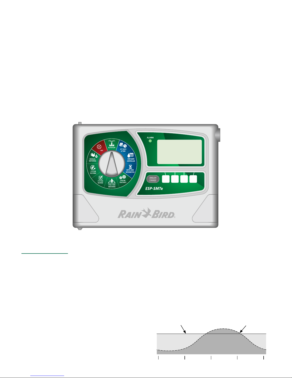
Welcome to Rain Bird
Thank you for choosing the ESP-SMTe Smart Modular Control System from Rain Bird. The ESP-SMTe is an indoor or
outdoor weather-based irrigation controller. Two ESP-SMTe
models are available that can be expanded up to 22 stations by adding optional station modules:
• 4 Station Indoor Controller (ESP4SMTei)
• 4 Station Outdoor Controller (ESP4SMTe)
The Intelligent Use of Water®
We believe it is our responsibility to develop products that
use water eciently.
ESP-SMTe Controller Features
The ESP-SMTe has two programming mode options that
make watering adjustments based on inputs from the
weather sensor.
Simple Smart Mode
In Simple Smart mode, the ESP-SMTe acts like a traditional time-based controller. Watering is scheduled on
specic days, with xed start times and run times. Automatic adjustments are made to run times based on current
weather conditions.
Advanced ET Mode
In Advanced ET mode, the ESP-SMTe uses state of the
art technology to determine water needs for each zone
to ensure optimal landscape health with minimal water
usage. Advanced mode will change the irrigation schedule
daily based on water needs.
Time-Based Controller Water Use
ESP-SMTe Controller Water Use
Water
Savings
Winter Spring Summer Fall
Page 2
ESP-SMTe Controller User Manual
English
Introduction
Welcome to Rain Bird ................................................... 1
The Intelligent Use of Water® .........................................1
ESP-SMTe Controller Features .................................... 1
Simple Smart Mode ...........................................................1
Advanced ET Mode ............................................................1
Technical Support ......................................................... 2
Installation
Mount Controller .......................................................... 3
Wiring Connections ...................................................... 3
Connect Valves ....................................................................3
Connect Master Valve (optional) ...................................3
Connect Pump Start Relay (optional) ..........................4
Connect Power ....................................................................4
Station Expansion Modules ........................................ 5
Install Modules ....................................................................5
Station Numbering ............................................................6
Module Conguration ......................................................6
Connect Weather Sensor Wire to Controller ............ 6
Complete Controller Installation ............................... 6
Weather Sensor Installation ....................................... 7
Choose Location ................................................................7
Sensor Mounting Options ...............................................7
Mount Weather Sensor .....................................................8
Connect Weather Sensor Wire .......................................8
Normal Operation
Controls and Indicators ............................................... 9
Weather Sensor Features ............................................ 9
Operating Modes ........................................................ 10
AUTO RUN ..........................................................................10
OFF ........................................................................................ 10
Simple Smart Programming
Set Date and Time .......................................................11
Congure Controller ..................................................11
Set Site Info ........................................................................ 11
Set Schedule ...................................................................... 12
Review Settings ................................................................ 13
Input Zone Information ............................................. 14
Set Zone Run Times ........................................................14
Set Grow-In Schedule ..................................................... 14
Special Features .......................................................... 15
Event Days O ...................................................................15
Short Circuit Test .............................................................. 15
Advanced Controller Setup ..........................................15
Select Programming Mode .......................................... 16
Advanced Zone Setup ................................................... 16
Save Contractor Defaults .............................................. 16
Set Units .............................................................................. 16
Fine-Tune Watering .................................................... 17
System Review ............................................................17
Controller Settings .......................................................... 17
Zone Settings .................................................................... 17
Weather Data ....................................................................18
Weather Log ......................................................................18
Event Log ............................................................................ 18
System Restore ............................................................ 19
Contractor Defaults......................................................... 19
Factory Defaults ............................................................... 19
Manual Watering.........................................................20
Water Individual Zone ....................................................20
Water All Zones ................................................................20
Water Selected Zones ....................................................20
Advanced ET Programming
Weather Based Irrigation Overview ........................ 21
Factors That Aect Irrigation .................................... 21
Weather ............................................................................... 21
Soil Type .............................................................................. 21
Irrigation Scheduling ................................................. 21
Evapotranspiration (ET) ................................................. 22
Plant Available Water (PAW)......................................... 22
Management Allowed Depletion (MAD) ................22
Congure Controller ..................................................22
Step 1. Enter Site Location ...........................................22
Step 2. Set Allowed Watering Days ..........................23
Step 3. Block One Day a Week .................................... 23
Step 4. Set Allowed Watering Windows ..................24
Step 5. Review .................................................................. 24
Input Zone Information ............................................. 25
Zone Setup Wizard .......................................................... 25
Copy Zone to Zone .....................................................30
Options
Reset Button ................................................................ 30
Remote Accessories ....................................................30
Troubleshooting
Watering or Electrical Issues ..................................... 31
Alarms and Notes .......................................................33
Technical Support
Questions?
For help setting up and operating
the Rain Bird ESP-SMTe Controller,
scan the QR code to visit
www.rainbird.com/espsmte
Additional user documentation is
available under the Manuals & Literature tab, including:
• User Manual (this document)
• Contractor’s Manual (full operations manual)
• Interactive Site Prole Chart
• Foreign Language Support
To learn more about Rain Bird irrigation systems and ourRain Bird Academy training programs, visit:
www.rainbirdservices.com/training
To see instructional videos for the ESP-STMe, visit
www.youtube.com/
Or call Rain Bird toll free Technical Support at
1-800-724-6247 (USA and Canada only)
2
ESP-SMTe Controller
Page 3
Installation
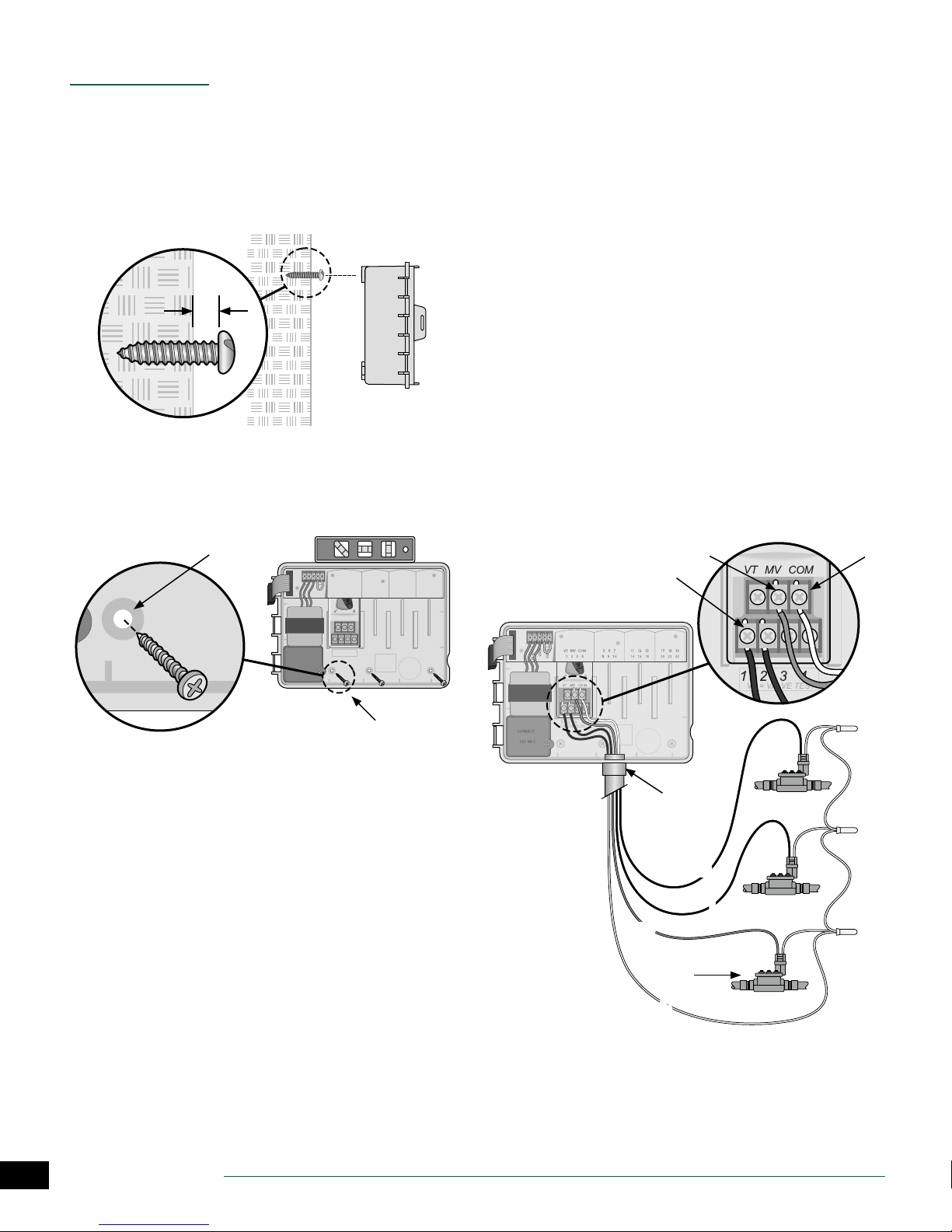
Mount Controller
Drive a mounting screw into the wall, leaving an 1/8
A
inch gap between the screw head and the wall surface
(use the supplied wall anchors if necessary), as shown.
Locate the keyhole slot on back of the controller unit
B
and hang it securely on the mounting screw.
A
1/8 IN.
B
Wiring Connections
Connect Valves
Route all eld wires through the opening at the
A
bottom or back of the unit. Attach conduit if desired,
as shown.
WARNING: Do not route the valve wires through the
same opening as the power wiring.
Connect one wire from each valve to the terminal on
B
the base module or Station Module that corresponds
to the desired station number (1-22).
Connect a eld common wire (C) to the common
C
terminal (C) on the base module. Then connect the
remaining wire from each valve to the eld common
wire, as shown.
To perform a Valve Test, connect the common wire to the
D
“COM” terminal and the power wire to the “VT” terminal.
This will immediately turn the valve “ON” .
Open the front panel, and drive three additional
C
screws through the open holes inside the controller
and into the wall, as shown.
C
VT MV COM 567 11 12 13 17 18 19
GND
1234 8910141516202122
SENS
24VAC
VT MV COM
1234
VT=VALVETEST
CONNECT
120 VAC
Connect Master Valve (optional)
Connect a wire from the master valve (M) to the
E
master valve terminal (MV) on the base module. Then
connect the remaining wire from the master valve to
the eld common wire, as shown.
E C
B
A
2
3
ESP-SMTe Controller
MV
MASTER
VALVE
C
C
1
E
Page 4
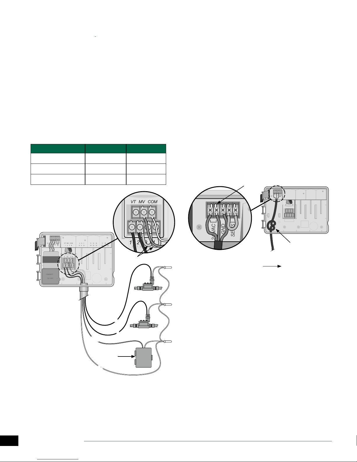
Connect Pump Start Relay (optional)
The ESP-SMTe can control a pump start relay, to turn the
pump on and o as needed.
Connect a wire from the pump start relay (PSR) to the
A
master valve terminal (M) on the base module. Then
connect another wire from the pump start relay to the
eld common wire, as shown.
To avoid the possibility of damage to the pump,
B
connect a short jumper wire from any unused
terminal(s) to the nearest terminal in use, as shown.
NOTE: The ESP-SMTe controller DOES NOT provide
power for a pump. The relay must be wired according
to manufacturer instructions.
Only the following Rain Bird pump start relay models are
compatible with the ESP-SMTe:
Description Note Model No.
Universal Pump Relay 110 volt only PSR110IC
Universal Pump Relay 220 volt only PSR220IC
Dual Pole Pump Relay 110/120 volt PSR110220
Connect Power
WARNING: DO NOT plug in the transformer or con-
nect external power until you have completed and
checked all wiring connections.
WARNING: Electric shock can cause severe injury or
death. Make sure power supply is turned OFF before
connecting power wires.
Indoor Model
Route the transformer power cord through the
A
conduit opening at the bottom left of the unit. Knot
the cable/cord inside the controller cabinet to prevent
it from being pulled out.
WARNING: Do not route the power cord through the
eld wire opening at the bottom right of the unit.
Connect the two power wires on the cord to the two
B
24VAC terminal connections on the controller.
Connect the ground wire on the cord to the GND
C
terminal.
Plug the transformer into an electrical outlet.
D
B
VT MV COM 567 11 12 13 17 18 19
GND
1234 8910141516202122
SENS
24VAC
VT MV COM
NOTE: Connec-
tion to pump
and external
power not
shown. Refer to
pump installation instructions.
PSR
PUMP START
RELAY
C
1234
VT=VALVETEST
A
B
2
1
D
TO EXTERNAL
POWER SUPPLY
A
4
ESP-SMTe Controller
Page 5
Outdoor Model
Power Wiring Connections
Black supply wire (hot) to the black transformer wire
White supply wire (neutral) to the white transformer wire
Green supply wire (ground) to the green transformer wire
Locate the transformer wiring compartment in
A
the lower left corner of the controller unit. Use a
screwdriver to remove the cover and expose the
transformer connection wires.
Route the three external power source wires through
B
the conduit opening at the bottom of the unit and
into the wiring compartment.
Using the provided wire nuts, connect the external
C
power source wires (two power and one ground) to
the transformer connection wires inside the wiring
compartment.
WARNING: Ground wire must be connected to
provide electrical surge protection. Permanently
mounted conduit shall be used for connecting main
voltage to the controller.
Verify that all wiring connections are secure, then
D
replace the wiring compartment cover and secure it
with the screw.
C
VT MV COM 567 11 12 13 17 18 19
GND
1234 8910141516202122
SENS
24VAC
VT MV COM
1234
VT=VALVETEST
A
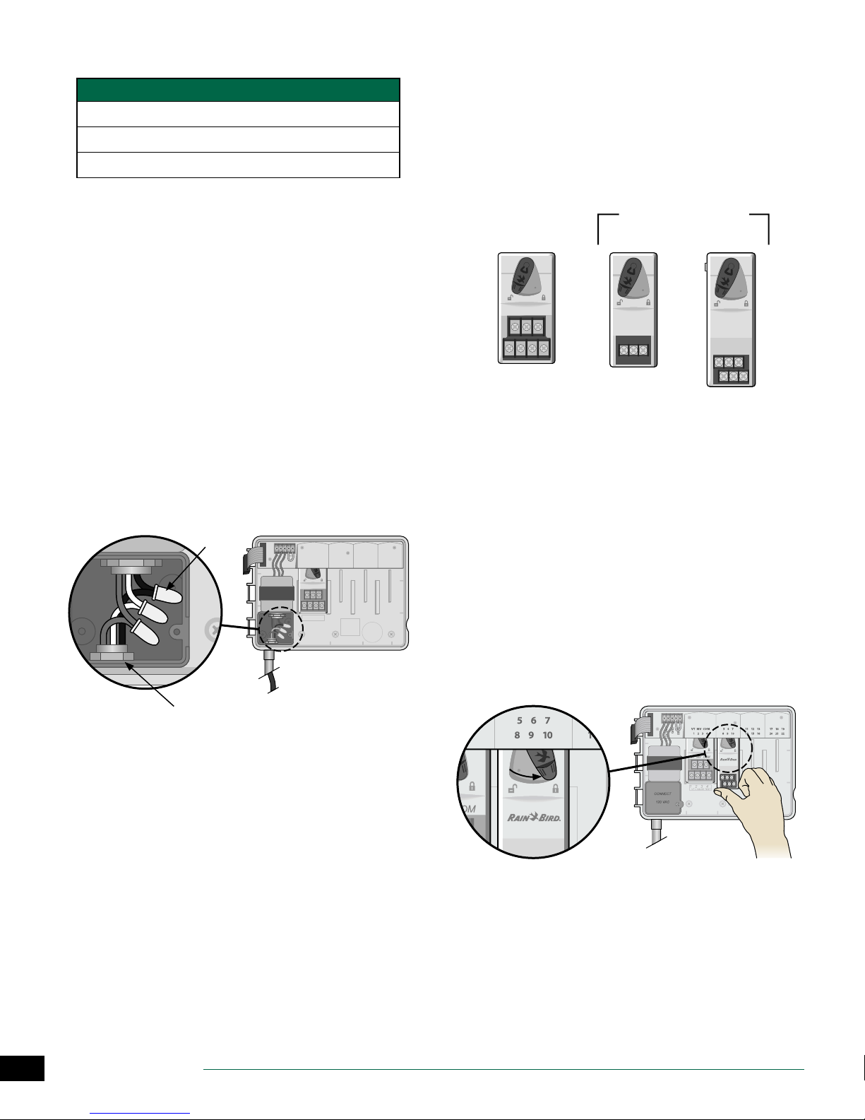
Station Expansion Modules
Optional Station Modules are installed in the empty slots to
the right of the base module to increase the station capacity up to 22 stations.
NOTE: For ideal station sequencing, it is recom-
mended that a 6-Station module always be installed
in Bay 2. For more details see the Station Numbering
section.
Base Module
(included)
VT MV COM
Install Modules
Verify the securing lever on the module is in the
A
unlocked position (slide to the left).
Place the module under the desired slot between the
B
plastic rails.
Push the module up into the slot until secure.
C
Slide the securing lever to the locked position (slide
D
to the right).
REPEAT for additional modules.
NOTE: Modules can be installed or removed with OR
without AC power connected. They are considered
“hot-swappable”.
Expansion Modules
(sold separately)
3-STATION
(ESPSM3)
6-STATION
(ESPSM6)
B
5
ESP-SMTe Controller
D
BC
Page 6

Station Numbering
Fixed Station Numbering Description
The controller is congured with Fixed Station Numbering.
Each bay is set up to accept a 6 station module and reserve
the station number for future use if a 6 station module is
NOT installed in Bays 2, 3 or 4.
Station numbers are pre-assigned as follows:
Bay 1 Bay 2 Bay 3 Bay 4
VT MV COM 567 11 12 13 17 18 19
1234 8910141516202122
Connect Weather Sensor Wire to
Controller
Begin by running 18-2 AWG, UV rated wire from sensor
A
to controller (200 ft. max.)
NOTE: 25 feet of 18-2 AWG, UV rated wire is provided.
Strip wire insulation approx 3/8” and insert leads into
B
connector located on back of front panel (polarity not
important).
C
VT MV COM
Example Of Recommended Installation For 19 Stations
Module Conguration
Example of installation with station numbering gaps:
• A total of 19 stations are installed.
• The Base Module is installed in Bay 1 and uses Stations
1 through 4.
• A 6-Station Expansion Module is installed in Bays 2 and
3 using Stations 5 through 16.
• A 3-Station module is installed in Bay 4 and uses stations numbered 17 through 19.
Because a 3-Station module is installed in Bay 4, only the
rst three station numbers assigned to that bay will be used
and the unused numbers will be “reserved” for future use.
During programming, the controller will skip any unused
station numbers, creating a gap in station numbering.
For the previous example, the rst screen of the Zone Setup
Wizard is displayed. The “No Module” message indicates
there is no module associated with Zone 14.
B
Route the two wires through the provided channel
C
and out through one of the knockouts, located in the
bottom of the controller cabinet.
Complete Controller Installation
Reinstall and reconnect the front panel.
A
Apply power to the controller and test the system.
B
NOTE: The electrical connections can be checked
even if water is not available. If water is available and
you would like to test some or all of your stations, use
the Test All Stations feature of the controller.Weather
Sensor Installation
NOTE: Station numbering gaps will not prevent the
controller from operating properly. It only aects
station numbering. During programming when
connected to AC power, the controller will skip any
unused stations where a module is not installed.
6
ESP-SMTe Controller
Page 7
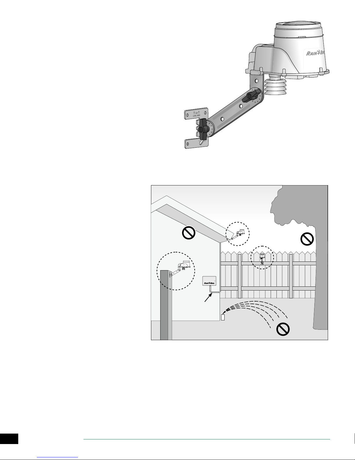
Weather Sensor Installation
Choose Location
• Select a convenient outdoor location in close proximity (wire-run distance is 200 feet maximum) to the ESPSMTe controller. Place in an unobstructed area away
from reective heat so that the unit can provide accurate on-site temperature and rainfall measurements.
• Mount the unit at least 6 feet above the ground surface to accurately measure ambient temperature. Suggested installation locations include the eave of a residence roof, a wooden fence post, etc.
• The sensor mounting bracket is designed to mount
on any vertical surface. Easy adjustment of the mounting arm ensures the installed sensor is level. UV rated
#16AWG or #18AWG wire is recommended for the communication wires if more than 25 feet is required.
Sensor Mounting Options
Do’s
• Mount the weather sensor at least six feet
above grade.
• Ensure that sensor is free from obstructions
to allow for collection and accurate measurement of rainfall.
• Sensor does not require direct sun to work
correctly provided any shade or other
obstruction does not block rainfall.
Don’t’s
• Do NOT install sensor in a location where
spray from a sprinkler will collect in the sensor.
• Do NOT install the sensor where rainfall will
be reduced or blocked from entering the
sensor funnel
• Do NOT install the sensor where it will be
impractical to service – the rain sensor may
require cleaning depending on the amount
of leaves, dust, etc that may collect in the
debris screen, funnel, or tipping bucket rain
sensor.
MOUNTED
ON POST
SENSOR WIRE
(MAX 200 FT.)
MOUNTED ON
ROOF EAVE
MOUNTED
ON FENCE
CONTROLLER
7
ESP-SMTe Controller
Page 8
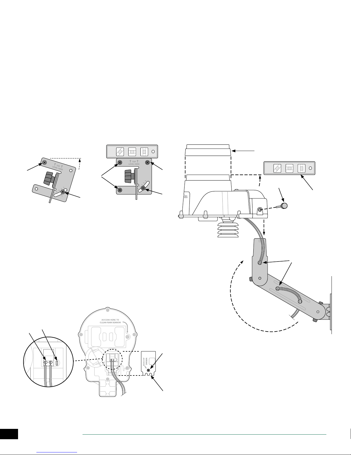
Mount Weather Sensor
Begin by running the communication wire to the location
where the sensor will be mounted.
Place the mounting bracket base assembly against
A
a mounting surface that permits the top of the
mounting bracket to be adjusted to vertical. Drive a
screw into the upper left hole of the base (do not
tighten completely).
Drive a second screw into the middle area of the
B
adjustment slot, located on the lower right corner of
the mounting base.
Level the mounting base and hold it in place, then
C
tighten the screw in the adjustment slot.
Tighten the upper left screw, then drive the two
D
remaining screws into the mounting base, securing it
to the mounting surface.
Feed the communication wire(s) through the three
E
holes in the mounting arm, providing “strain-relief” for
the wires. Leave enough extra wire at the top end so
the sensor pod can easily be installed and removed.
Mount the sensor housing assembly to the top of
F
the mounting arm. Align the mounting hole on the
bracket with the arm and tighten using the provided
thumb-screw
Adjust each of the mounting arms to assure that the
G
top of the sensor is secured and level.
Press the sensor debris cover onto the top of the
H
sensor.
H
A
D
B
Connect Weather Sensor Wire
Loosen the captured-screw of the wiring compartment
A
cover to expose the sensor housing and green wiring
connector within.
Strip the two wire leads 1/4” and insert into the
B
connectors (polarity is not important).
If AC power is available, the green LED will blink. Once
C
communication is established between the sensor
and controller, the LED will light solid.
Re-attach the wiring compartment cover and route
D
the wire through the two openings. Then re-tighten
the captured screw to secure the cover.
C
B
D
C
F
G
E
8
ESP-SMTe Controller
A
D
Page 9
Normal Operation
AUTO MODE
Monday 02 May 2016
Next
Estimate
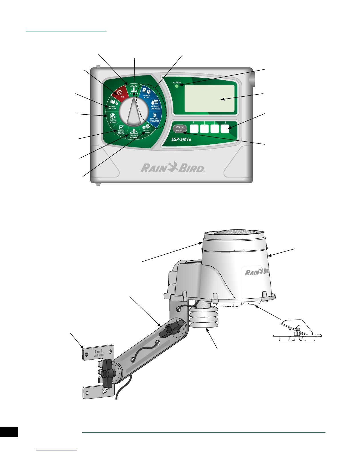
Controls and Indicators
AUTO RUN: Watering
occurs automatically
OFF: Cancels all irrigation
Manual Watering: Start
watering selected zones
immediately
System Restore: Restore
contractor and factory
default settings
System Review: Review
controller settings and
logs
Fine-Tune Watering:
Adjust run times by zone
Special Features: Block
irrigation on days of special events
Key operational features of the ESP-SMTe Controller:
Programming Dial
Initial Controller & Zone
Set-Up Dial Positions
05:00 PM
Irrigation
05 May
ESP-SMTe Controller Front Panel
Alarm Light: Illuminates
when conditions prevent
watering
Large Back Lit DotMatrix Display
Programming Buttons:
Press and Hold to accelerate
settings
English/Spanish Button:
For easy switching of display
language
Remotely Programmable: Using 9V battery
(installed inside front panel)
Weather Sensor Features
Removable Debris Screen:
Easily remove and clean when
clogged
Adjustable Mounting Bracket
Mounting Base: Install on eave,
roof, side of house or post
Solar Shield With Temperature
Sensor: Measures temperature
and sends to controller
NOTE: When installing the weather sensor,
keep away from radiating heat, etc.
Sensor
Housing
Removable Tipping
Rain Bucket: Measures
rainfall amounts and
sends to controller
9
ESP-SMTe Controller
Page 10
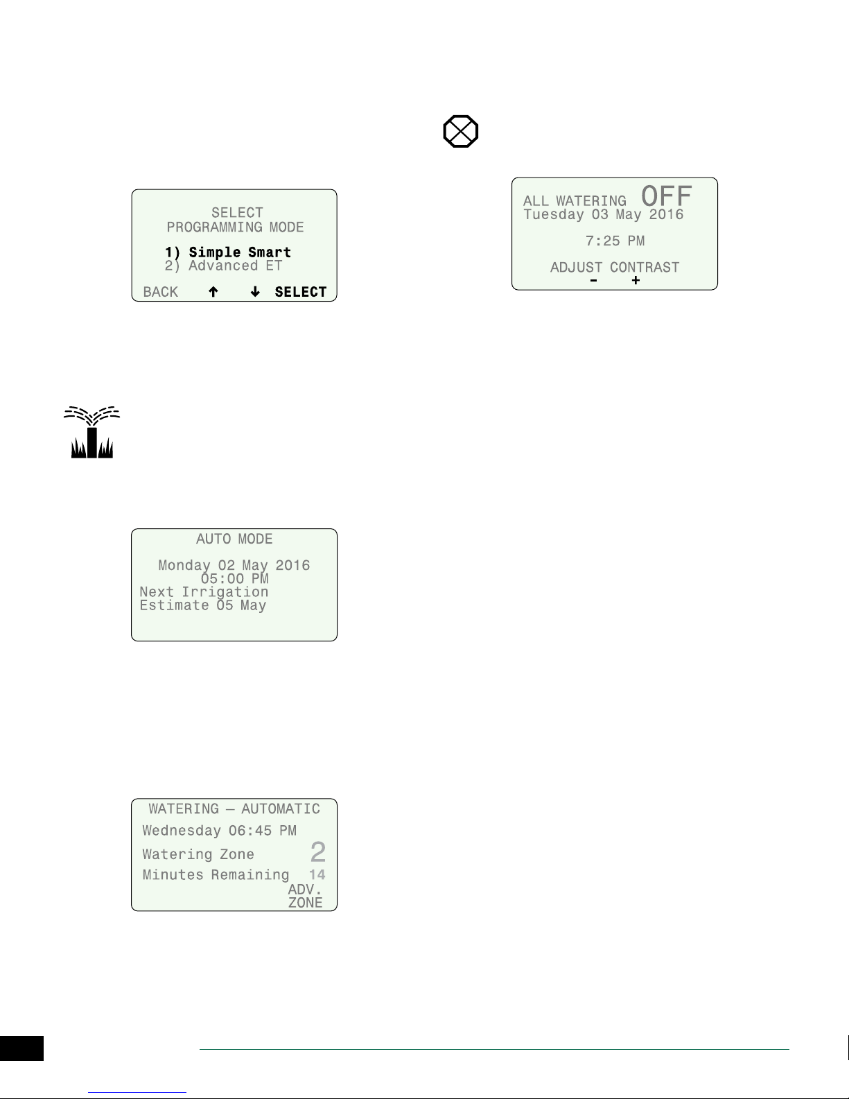
Operating Modes
When the ESP-SMTe Controller is powered on for the rst
time, the option to select a programming mode is displayed.
This screen is also available under the Advanced Control-
ler Setup dial position (see page 15) or after a Factory
Default reset.
AUTO RUN
AUTO RUN is the normal operating mode for the controller.
Irrigation starts automatically when required, and the next
estimated watering date is displayed.
Turn the dial to AUTO RUN.
OFF
Cancel all active watering immediately and stop
automatic irrigation.
Turn the dial to OFF.
• Press – or + to adjust the LCD contrast if desired.
Controller Conguration and Zone Information settings
remain stored in memory while the controller is OFF or if
there is a loss of power. Date and time are also maintained
for up to 10 years by an internal battery. A 9V battery is not
required to maintain settings or date and time.
NOTE: Automatic irrigation will NOT occur if the con-
troller remains in OFF mode.
In AUTO Mode:
• The display shows the current day of the week, date,
time, and the next estimated watering day.
NOTE: On a scheduled watering day, “Next Irrigation
Estimate will change to “Adjusted: 0%” and display any
automatic adjustments to irrigation.
During Watering:
• The display shows the current day, current active zone,
and the Time Remaining for that Zone.
10
ESP-SMTe Controller
Page 11
Simple Smart Programming
This section provides instructions to setup and operate the
ESP-SMTe.
To program in Simple Smart mode, select Simple Smart on
the Select Programming Mode screen. This screen is available under the Advanced Controller Setup dial position
(see page 15) or after a Factory Default reset.
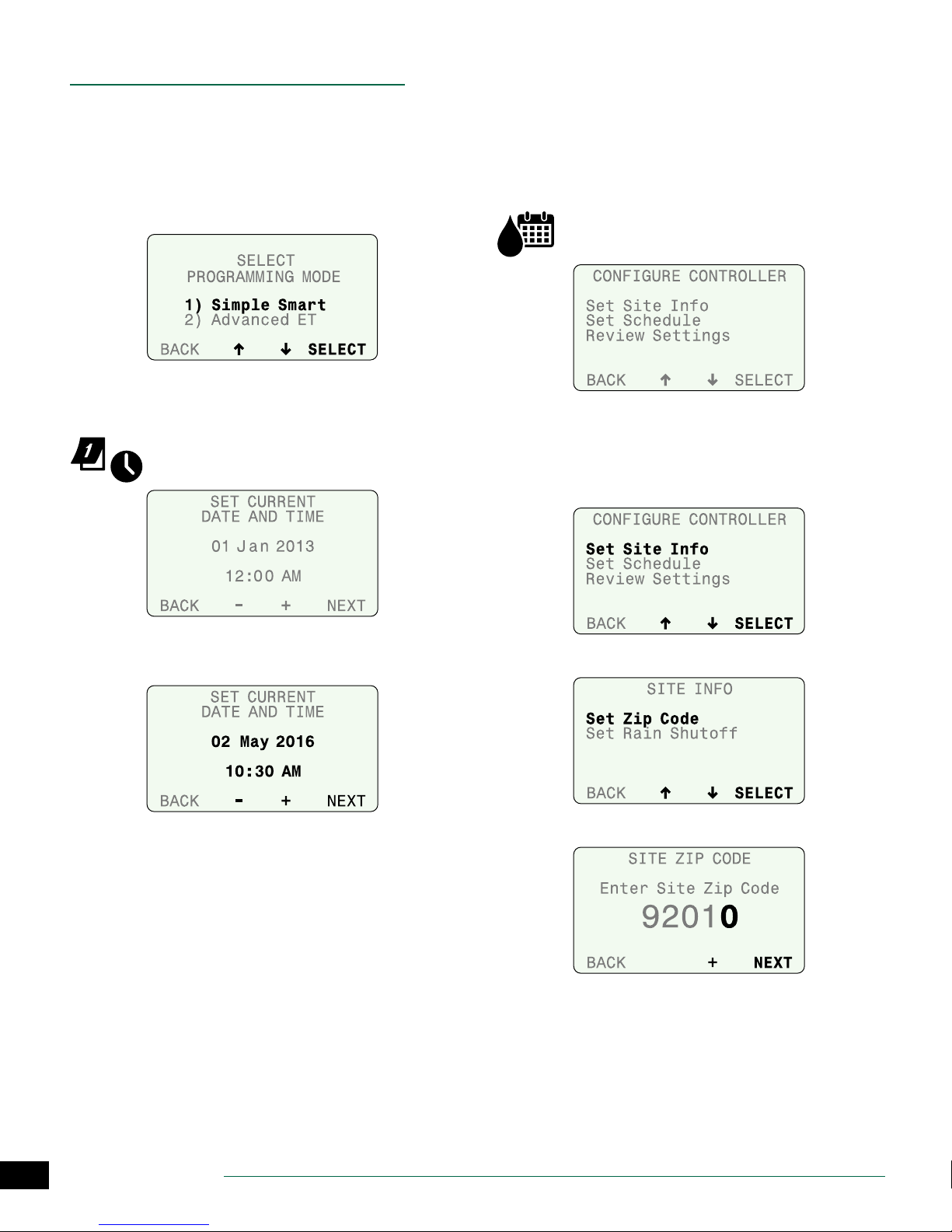
Set Date and Time
Set the current calendar Date and Time of day.
Turn the dial to Set Date & Time.
Congure Controller
Enter site location info and basic irrigation schedules.
In Simple Smart mode, congure the controller by entering
the site zip code for your site, selecting the days to water,
and entering the start times that watering will begin.
NOTE: For Advanced ET mode, see page 21.
Turn the dial to Congure Controller.
Set Site Info
Enter the zip code for your site and the Rain Shuto
parameters for rain sensor shuto.
Select Set Site Info.
A
Set the current month, day and year.
A
Set the current time.
B
Select Set Zip Code.
B
Enter the zip code for your site.
C
11
ESP-SMTe Controller
Page 12

Select Set Rain Shuto.
D
Enter the number of Days to delay watering when a
E
set amount of rain is detected; then press NEXT.
Set the amount of rain that will start the delay; then
F
press NEXT.
Press BACK to return to the Congure Controller
G
menu.
Set Schedule
For each Program (A and B), select the Days to Water and
the Start Times that irrigation will begin.
Select Set Schedule.
A
Select a watering day option.
D
NOTE: After selecting a watering day option, the
screen will automatically advance to Step 5, Block
One Day a Week.
Water Every Day:
No restrictions on days to water.
Days of the Week:
Set a custom weekly schedule.
• Press OFF or ALLOW to water on the selected day; then
press NEXT.
Press UP or DOWN until PROGRAM is blinking; then
B
press PGM SELECT to choose A or B.
Select Set Days to Water.
C
12
ESP-SMTe Controller
Even Days:
Water only on even calendar days.
Odd Days:
Water only on odd calendar days (except 31st).
Page 13

Cyclical
Water on a cycle of every 2 to 14 days.
Review Settings
Select Review Settings.
A
.
Press – or + to set the irrigation cycle and the date to
A
begin the cycle; then press NEXT.
Select a desired day of the week (or none) to Block
B
Watering.
Select Set Start Times.
C
Review the Site Info settings, then press MORE.
B
Review the Watering Day options and programmed
C
Start Times for Program A, then press MORE.
Review Watering Day options and programmed Start
D
Times for Program B, then press MORE.
Set the rst Start Time; then press NEXT START to enter
D
additional times (up to 6 total), or, press DONE to nish.
REPEAT Steps 2 - 7 for Program B if necessary.
13
ESP-SMTe Controller
Page 14

Input Zone Information
Enter run times for every zone and set up a watering
schedule for new plants.
NOTE: For Advanced ET mode, see page 21.
Turn the dial to Input Zone Information.
• The current programming mode is displayed. Press
MORE to continue.
Set Zone Run Times
Enter desired Run Times for each zone and program.
NOTE: Run Times should be entered based on the
hottest time of year for your location. The SMTe will
make adjustments to the Run Times in Simple Smart
mode based on local weather conditions.
Select the desired zone.
A
Select Program A or Program B.
B
Set the Run Time; then press NEXT.
C
Set Grow-In Schedule
New plants have dierent watering needs than plants that
are already established. New plants are watered every day
during a set Grow-In Schedule period, then are watered
according to regular schedules when the period ends.
Press + when OFF is blinking to enable the Grow-In
A
Schedule for the selected zone; press NEXT to return to
the Set Run Times screen.
Set the number of days the Grow-In period will last.
B
Set the number of Cycles per day (up to 8).
C
Set the Cycle time (duration of each Cycle).
D
Set the Start Time (time the rst Cycle begins).
E
Set the Start interval time (minutes between Cycles).
F
14
ESP-SMTe Controller
Page 15

Special Features
Select additional features and controller setup options.
Turn the dial to Special Features.
Event Days O
Event Days O allows you to select up to four dates to
block irrigation for special occasions up to a year in
advance.
Select Event Days O.
A
The test result for each zone is displayed; the test takes
about 30 seconds to complete.
Press RETEST to run the test again if desired.
B
NOTE: “NoMod” indicates that no module is present
for that station number.
Advanced Controller Setup
Set time delays between zones and set thresholds that
determine when the controller will suspend irrigation due
to weather conditions.
Select Adv. Controller Setup.
A
Press + to add a new date.
B
Set the date; then press NEXT to set additional dates.
C
To delete an Event Day O, select the date using NEXT
D
or BACK and press and HOLD -.
Short Circuit Test
Verify the integrity of the wires between the controller and
the valves.
Select Short Circuit Test.
A
Set each value; then press NEXT.
B
• Zone to Zone Delay sets a time delay between one station valve turning o and the next station valve turning
on.
• Suspend Watering When Rain Reaches value suspends irrigation when measured rainfall reaches the
specied amount.
• Suspend Watering When Temp Below value suspends
irrigation when the temperature falls below a specic
value.
15
ESP-SMTe Controller
Page 16

Select Programming Mode
After setting the Temp Below value on the Advanced Controller Setup screen (and pressing NEXT), the option to
switch programming modes is displayed.
• Select the desired programming mode.
Advanced Zone Setup
Set each zone to use (or not to use) an installed master
valve, pump start relay, or the ESP-SMTe Rain Gauge.
Select Advanced Zone Setup.
A
Press SAVE to save zone and controller settings to
B
Contractor Defaults.
Read the Warning; then press SAVE.
C
Current Settings are saved; press CONTINUE.
D
Set Units
Set the Time format (AM/PM or 24-Hour) and Units format
(English or Metric) that is displayed by the controller.
Select Set Units.
A
Select the desired zone.
B
Select YES for Auto-Adjust to choose whether a zone’s
C
durations are adjusted due to weather.
Select YES if MV is energized when the selected zone
D
starts.
Select YES if the zone’s irrigation should be suspended
E
due to rain or not (e.g. plants under a covered patio).
Save Contractor Defaults
Save the current Congure Controller and Input Zone
Information settings for all zones to memory.
Select Save Contractor Dts.
A
Select the desired Time Format.
B
Select the desired Units Format.
C
16
ESP-SMTe Controller
Page 17

Fine-Tune Watering
Adjust the calculated run time for each zone.
Turn the dial to Fine-Tune Watering.
Press BACK or NEXT to select the zone to adjust.
A
Press – or + to set the adjustment percentage for the
B
selected zone.
After making any adjustments, return the dial to
C
AUTO RUN.
If minor adjustments are required to calculated run times,
you can increase or decrease run times for ET zones by a
selected percentage. These adjustments will apply until
you set the value back to 0.
The Fine Tune % By Zone value can be adjusted from -60%
to +60%. For example, if a +50% adjustment is set, then a
calculated run time of 10 minutes will become 15 minutes.
NOTE: Fine-Tune Watering adjustments always apply
to all zones in Simple Mode.
NOTE: Fine Tune settings can be adjusted for Newly
Planted zones, but will not take eect until the Newly
Planted mode expires.
Controller Settings
Review Congure Controller settings.
Select Controller Settings.
A
Review location data and delay settings; then press
B
MORE.
Review Program A; then press MORE.
C
Review Program B then press MORE.
D
System Review
View system settings and weather information.
NOTE: The information under System Review is for
review purposes only. This allows the review of programming settings without accidentally making
unwanted changes.
Turn the dial to System Review.
Zone Settings
Review Input Zone Information and Advanced Zone Setup
settings.
Select Zone Settings.
A
17
ESP-SMTe Controller
Page 18

Review zone settings; then press MORE.
B
Review Weather Log; then press BACK.
B
Review Grow-In Schedule; then press BACK.
C
Weather Data
Review the current temperature and rainfall over the past
24 hours based on data from the SMTe Weather Sensor.
Select Weather Data.
A
Review Weather Data; then press BACK.
B
Event Log
Review notications and error messages concerning
irrigation events by date or by zone. Check these messages
if the controller is not operating as expected.
Select Event Log.
A
Events and alarms can be viewed by date or by zone.
B
NOTE: A table in the Contractor’s Manual on the web-
site (www.rainbird.com/esp-smte) lists all the messages that can appear in the Event Logs.
Weather Log
Review a daily log of high and low temperatures,
calculated ET values, and rainfall over the past month.
Select Weather Log.
A
18
ESP-SMTe Controller
Page 19

System Restore
Restore Contractor Default settings and restore original
Factory Default settings.
Turn the dial to System Restore.
Contractor Defaults
Restore settings that were saved using the Save Contractor
Defaults feature.
NOTE: Current settings are overwritten.
Select Contractor Defaults.
A
Factory Defaults
Restore the original factory default settings.
NOTE: All current zone settings are erased. Any settings
saved using Save Contractor Defaults are NOT affected.
Select Factory Defaults.
A
Press RESTORE to restore the Factory Defaults.
B
The following warning is displayed; press RESTORE.
C
Press RESTORE to restore the Contractor Defaults.
B
The following screen is displayed while the controller
C
recongures.
• When the restore is complete, the display returns to the
RESTORE SETTINGS menu.
The following screen is displayed while the controller
D
recongures.
When the restore is complete, the option to switch
E
programming modes is displayed.
Select the desired programming mode and begin
F
programming the controller per the mode selected.
>> For Simple Smart mode, go to page 11.
>> For Advanced ET mode, go to page 21.
19
ESP-SMTe Controller
Page 20

Manual Watering
Start watering immediately for selected zones or for all
zones.
NOTE: If Manual Watering is started during automatic
irrigation, the watering schedule is canceled for the
day and resumes on the next Allowed Watering Day.
Turn the dial to Manual Watering.
Water Individual Zone
Select Water Individual Zone from the Manual
A
Watering screen.
NOTE: A selected zone will be activated even if it is
not ENABLED. A zone that does not have an associated station module will display No Module.
Select the desired zone; then press NEXT.
B
Set the run time for the selected zone; then press
C
NEXT.
Water Selected Zones
Select Water Selected Zones from the Manual
A
Watering screen..
NOTE: Selected zones will be activated even if they
are not ENABLED. Zones that do not have an associated station module will display n/a.
Select the desired zone or zones.
B
Set the run time for every desired zone; then press
C
NEXT until you reach the end of your available zones.
NEXT will change to START; then press START.
D
During All Manual Watering:
The Watering - Manual screen shows the current zone and
time remaining.
Press – or + to adjust the time remaining if desired.
A
Press ADV. ZONE to advance to the next zone if
B
desired.
Water All Zones
Select Water All Zones from the Manual Watering screen.
A
NOTE: All zones will be activated even if they are not
ENABLED. Zones will not activate that do not have an
associated station module installed.
Set the run time for all zones; then press START.
B
20
ESP-SMTe Controller
To cancel watering, press CANCEL or turn the dial to
C
OFF for three seconds and then return the dial to the
AUTO RUN position.
Page 21

Advanced ET Programming
In the Advanced ET programming mode, the ESP-SMTe is a
fully “weather-based” irrigation system.
NOTE: A complete guide to programming in Advanced
ET mode is available at www.rainbird.com/esp-smte.
Weather Based Irrigation Overview
Watering is based on actual landscape needs instead of
the predetermined schedule used by “time-based” programming.
Current weather data from the SMTe Weather Sensor and
specic site conditions are used to automatically update
irrigation schedules so that plants only get water when it
is needed.
The ESP-SMTe in Advanced ET mode will use 30% to 50%
less water than a traditional time-based watering schedule.
Factors That Aect Irrigation
Weather
Local weather conditions will aect the amount of water
that plants need. Current weather data as well as historical
data such as wind speed and humidity are used for scheduling.
Soil Type
Dierent soil types vary greatly in the ability to hold water
and the rate that water lters down through the soil. The
Soil Type in each zone helps determine when plants need
water.
Irrigation Scheduling
1. Controller determines when irrigation is required.
The ESP-SMTe Smart Modular Control System
continuously monitors weather conditions onsite to determine when irrigation is required.
Clay Sand Loam
2. Controller schedules irrigation.
4. Controller monitors weather conditions.
21
ESP-SMTe Controller
3. Irrigation occurs.
Page 22

Evapotranspiration (ET)
The ESP-SMTe calculates water needs based on water lost
from the soil surface (evaporation) and water used by the
plants (transpiration). The rate that water is lost is called
evapotranspiration, or ET.
Plant Available Water (PAW)
The total amount of water that can be stored in the soil
for the plant is called Plant Available Water, or PAW. This
amount varies based on the soil type and plant root depth.
Management Allowed Depletion (MAD)
When the amount of water available to the plant gets too
low, irrigation is scheduled. This level is referred to as Management Allowed Depletion, or MAD and is set by the user
at the controller.
ET - The rate that
water is lost to
evapotranspiration.
Congure Controller
Enter site location info and basic irrigation schedules.
To program in Advanced ET mode, select Advanced ET on
the Select Programming Mode screen. This screen is available under the Advanced Controller Setup dial position
(see page 15) or after a Factory Default reset.
Congure the controller by entering site location information for your site, selecting the days to allow watering, and
entering the times that watering can occur.
Turn the dial to Congure Controller.
PAW - The
total amount
of water that
can be stored.
Factors that Determine Irrigation
MAD - When water
drops to this level,
irrigation is
scheduled.
Step 1. Enter Site Location
The ESP-SMTe controller will use historical weather data
(for wind speed and humidity) based on zip code or you
can enter custom values for your site.
NOTE: If outside the United States you must use Cus-
tom Data for Location.
Select Location by Zip Code
Select Enter Site Zip Code.
A
22
ESP-SMTe Controller
Page 23

Enter the complete zip code for your site; then press
B
NEXT.
Days of the Week
To set a custom weekly schedule, select By Days of the
Week.
If the zip code is correct, press YES.
C
Enter Custom Data for Location
Refer to the Contractor’s Manual on the Rain Bird website
to enter Custom Data.
NOTE: Contact your local weather station for Custom
Data (Latitude, Elevation, average Wind Speed and
Humidity).
Press OFF or ALLOW to set each day of the week as an
A
Allowed Watering day or a non-watering day.
When each day is set, press NEXT.
B
>> Go To Step 4, Set Allowed Watering Windows
NOTE: For details on other options, see the Contrac-
tor’s Manual on the Rain Bird website.
Step 3. Block One Day a Week
Select a specic day of the week to block irrigation (only if
No Restrictions is selected). The controller will always block
irrigation on this day.
• Select a day of the week (or none) to block irrigation.
Step 2. Set Allowed Watering Days
Check with your local water authorities to see if there are
any current water restrictions in eect that would limit the
days or times of day that you can schedule irrigation.
Select one of the following options to determine the days
that the controller is allowed to water.
No Restrictions
• Select No Restrictions if there are no restrictions on
days that you can irrigate.
>> Go To Step 3, Block One Day a Week
23
ESP-SMTe Controller
Page 24

Step 4. Set Allowed Watering Windows
Set a time that irrigation can occur on Allowed Watering
Days.
Set the start and end times for the 1st Watering
A
Window; then press NEXT.
If desired, Set the 2nd Watering Window to ON and set
B
the start and end times; then press NEXT.
Set the Daily Water Window for new plants and zones
C
that may water every day regardless of allowed
watering days; then press NEXT.
Step 5. Review
Review the Congure Controller settings.
Press BACK to make changes if desired, then press
A
MORE.
Review settings.
B
Review settings and press DONE.
C
NOTE: The Daily Water Window allows irrigation of
new plants every day, and is not aected by Allowed
Watering Days, Blocked Days or Event Days O. The
number of days that a Daily Water Window is in eect
is set in the Enter Plant Maturity step under Input
Zone Information.
Set Rain Shuto (days and inches); then press NEXT.
D
NOTE: Once the desired amount of rain has been
exceeded, the controller will stop watering time based
and grow-in zones for the number of Full Days specied. Full Days begin at midnight so 1 Full Day is the
rest of today and all of tomorrow.
24
ESP-SMTe Controller
Page 25

Input Zone Information
Enter site information for each zone.
Detailed site information about soil, sprinklers, and plant
types is needed to determine irrigation schedules.
NOTE: For more details, see the Contractor’s Manual
on the Rain Bird website.
Turn the dial to Input Zone Information.
Press ENABLE to enable the selected Zone; then press
B
NEXT.
• The current programming mode is displayed. Press
MORE to continue.
Zone Setup Wizard
• Select Zone Setup Wizard.
Step 1. Enter Zone Number
The number of available zones depends on the number
and type of station modules that are installed.
NOTE: If you select a zone number that does not have
an associated module installed, “No Module” is displayed.
Select the desired Zone Number; then press NEXT.
A
NOTE: Zone information can still be entered when
the Zone is in OFF mode, but the controller will not
include the zone in irrigation scheduling. This is useful
if you want to pre-program all your zones.
Step 2. Select Soil Type
Dierent soil types vary greatly in the ability to hold water
and the rate that water lters down through the soil.
To help determine your soil type, highlight an option and
press Help for a brief soil description.
NOTE: You can also refer to the Soil Type section in the
Appendix of the Contractors Manual on the Rain Bird
website.
• Select the soil type for your site.
NOTE: The default values for soil data that the control-
ler uses to determine irrigation are listed below. The
soil type you choose will aect irrigation frequency
(number of days between watering) and watering run
times.
25
ESP-SMTe Controller
Page 26

Soil Types
Available
Water
Soil Type
Sand 0.06” 0.60” 50%
Loamy
Sand
Sandy
Loam
Loam 0.17” 0.35” 50%
Clay
Loam
Silty Clay 0.17” 0.15” 40%
Clay 0.17” 0.10” 35%
(inches of
water per
inch of soil)
0.08” 0.50” 50%
0.12” 0.40” 55%
0.18” 0.20” 50%
Basic
Intake Rate
(inches per
hour)
Management
Allowed
Depletion
(MAD)
Step 3. Select Zone Type
Select a Zone Type based on the type of sprinkler that is
installed in the selected zone to help the controller schedule watering times..
Select the Zone Type or select Time-Based.
A
Step 4. Select Sprinkler Type
Every type of sprinkler or drip system will apply water at a
dierent rate, called the Net Application Rate. This rate is
dened as the amount of water that your type of sprinkler
can apply to the landscape in a certain period of time.
NOTE: For example, a sprinkler with an Application
Rate of 2 inches per hour can apply twice as much
water in a period of time as a sprinkler with a rate of
only 1 inch per hour.
The Net Application Rate options in Step 4 depend on the
Zone Type selection made in Step 3.If selected Zone Type
is Sprinkler:
Select the appropriate sprinkler type from the list.
A
Adjust the default Net Application Rate if desired;
B
then press NEXT.
NOTE: Time-Based is typically used for zones that irri-
gate potted plants or is used to ll a pool.
Select the desired option for the Water Window.
B
NOTE: If 1st+2nd: Restricted is selected, any restric-
tions entered during Controller Conguration will be
applied. If Daily Water Window is selected, the pro-
grammed Daily Water Window will be used and zones
will be allowed to water only if required.
NOTE: Increasing the default Net Application Rate
will decrease irrigation run times, and decreasing the
value will increase the run times.
Default Net Application Rates
Sprinkler Type
Sprays 1.60
Rotors 0.45
Rotary Nozzle 0.50
Bubblers 2.50
>> Go To Step 5, Cycle+Soak
Net Application
Rate (in/hr)
26
ESP-SMTe Controller
Page 27

12
12
Run Time
30 min
Application Rate
39
6
2 in/hr
Run Time
1 hr
Application Rate
39
6
1 in/hr
Application Rates vs. Run Time
If selected Zone Type is Point Source Drip:
Use the instruction screens on the display as a guide
C
to determine proper Application Rate.
Adjust the default Net Application Rate if desired;
D
then press NEXT.
Step 5. Cycle+Soak
Cycle+SoakTM divides your irrigation Run Time into several Cycles in order to prevent run-o on steep slopes. The
unit will then Soak for a minimum amount of time to allow
water to reach the root zone.
For example, Cycle+SoakTM will break up a 30 minute Run
Time into several cycles instead of watering continuously
for the entire period. It may water for 10 minutes, let the
water soak into the soil, run for 10 more, etc. This prevents
waste due to run-o and all the water will reach the roots.
Select the Slope degree (by pressing – or +) that best
A
represents the zone topography; then press NEXT.
(Divided into three 10 min cycles)
TM
30 min Run Time
NOTE: Increasing the Net Application Rate will
decrease irrigation run times, and decreasing the
value will increase the run times.
>> Go To Step 5, Cycle+Soak
If selected Zone Type is Inline Grid Drip:
Set the values for emitter Flow Rate, Emitter Spacing,
E
and Row Spacing; then press NEXT.
Change the Adjust Factor to adjust the Estimated
F
Application Rate if desired; then press NEXT.
NOTE: For detailed information on setting up Point
Source Drip and Inline Grid Drip systems, see the Contractor’s Manual on the Rain Bird website.
>> Go To Step 5, Cycle+Soak
No Wasted Water
(run-o is
eliminated)
All applied water
reaches the roots
Watering With Cycle+Soak
The Automatic mode is selected. To accept the
B
automatically calculated cycle and soak values, press
NEXT.
>> Go To Step 6, Select Plant Type.
TM
27
ESP-SMTe Controller
Page 28

To use Custom values, press + to select Custom; then
C
press NEXT.
Adjust the Maximum Cycle and Minimum Soak values;
D
then press NEXT.
>> Go To Step 6, Select Plant Type.
Step 6. Select Plant Type
Dierent plant types have dierent water needs. Select the
dominant plant type for the selected zone.
NOTE: To use Custom Plant Factors, refer to the Con-
tractor’s Manual on the Rain Bird website.
• Select the plant type for the zone.
>> If a Grass Lawn type is selected, skip Step 2.
If a plant type other than Grass Lawn is selected:
Select an estimated Plant Water Need.
A
NOTE: Increasing the Water Need (Low to High) will
increase irrigation frequency (water more often).
Decreasing Water Need will decrease irrigation frequency (water less often).
Enter Root Depth (or accept default value for selected
B
plant type); then press NEXT.
NOTE: Increasing the root depth will decrease irriga-
tion frequency (water less often) and increase watering run times. Decreasing the root depth will increase
irrigation frequency (water more often) and decrease
run times.
>> If Grass Lawns was selected, Go to Step 8,
Enter Shade Factor.
>> For all other Plant Types, Go to Step 7,
Enter Plant Density.
Grass Lawns options:
The gures below show the dierence between Cool and
Warm Season Varieties.
Cool Season Variety Warm Season Variety
Most “Cool Season” grasses
do not spread through
runners, but rather from
actual seed that germinates. Cool Season Varieties usually have individual
blades that grow in a vertical orientation.
28
ESP-SMTe Controller
Most “Warm Season” grasses
grow (spread) through
runners that branch out
horizontally from the established lawn or from planted
stolons. In general, Warm
Season grasses go dormant
in the winter.
Step 7. Select Plant Density
Plant Density is the relative amount of foliage (leaf surface
area and plant spacing) in the zone. This applies to all other
Plant Types (Step 6) except Grass Lawn.
• Select the appropriate plant density for the zone.
NOTE: Increasing the Plant Density (Sparse to Dense)
will increase irrigation frequency (water more often).
Decreasing the Plant Density will decrease irrigation
frequency (water less often).
Page 29

Step 8. Select Shade Factor
Shade Factor is the approximate amount of time that plants
are exposed to direct sunlight each day.
• Select the appropriate shade factor for the zone.
NOTE: Increasing the Shade Factor (less exposure to
the sun) will decrease irrigation frequency (water less
often). Decreasing the Shade Factor (more exposure
to the sun) will increase irrigation frequency (water
more often).
Step 9. Enter Rell Point
• Adjust the Rell Point if desired; then press NEXT.
For Newly Planted Plants:
Select Newly Planted (Grow-in Period).
A
Set the number of days (1-199) for the desired Daily
B
Period.
Set the desired number of Cycles per Day (1-8).
C
Set the desired Minutes per Cycle (1-30); then press
D
NEXT.
NOTE: The graphic on the left of the screen shows the
amount of water in the soil. When this amount drops
to the level indicated by the arrow (Rell Point) then
irrigation is scheduled. Increasing the Rell Point will
cause shorter, more frequent irrigation, and decreasing the Rell Point will cause longer, less frequent irrigation
Step 10. Select Plant Maturity
New plants have dierent watering needs than plants that
are already established. New plants are watered every day
during the daily Grow-in Period, then are considered Established when the Grow-in Period ends.
For Established Plants:
• Select Established.
Step 11. Select Next Action
After programming, select the desired Next Action.
• Program Next Zone returns to the Select Zone screen
(Step 1) to program another zone.
• Review This Zone displays all the zone information
selected during programming.
• Change This Zone Data returns to the Select Zone
screen (Step 1) to edit zone information.
• Copy Zone To Zone displays the Copy Zone Data
screen.
>> Go to Step 11, Select Next Action.
29
ESP-SMTe Controller
Page 30

Copy Zone to Zone
Copy zone information from one zone to another zone.
Turn the dial to Input Zone Information.
Select Copy Zone to Zone.
A
Select the source Zone number (Copy From Zone).
B
Select up to three destination zones (To Zone); then
C
press NEXT.
Options
Reset Button
The Reset button resets the controller. Active watering is
canceled, and all previously programmed conguration
and zone information remains stored in memory. Irrigation
will resume on the next Allowed Watering Day.
Insert a small tool into the access hole and press until the
controller is reset.
NOTE: We suggest using a non-metallic object such as
a pencil or pen to press the Reset button.
Select COPY if the selections are correct.
D
Select QUIT to re-enter selections.
E
NOTE: If QUIT is selected, NOT COPIED will be dis-
played on the screen.
When the copy is complete, press NEXT.
F
Remote Accessories
NOTE: Use only Rain Bird approved devices with 5 pin
accessory port. Unapproved devices may damage
controller and void warranty.
• The front panel provides a port for the use of external
devices.
30
ESP-SMTe Controller
Page 31

Troubleshooting Watering or Electrical Issues
Symptom Possible Cause Correction
Automatic irrigation is
not occurring.
Dial is set to OFF. Set the dial to AUTO RUN.
A NOTE or ALARM condition is active
that prevents irrigation.
NOTE – All Zones Are Off Unit is new. This condition exists when the controller has been installed but has not been
NOTE – All Zones Are Off
Unit has previously been irrigating
NOTE – All watering days are off This is handled the same as “All Zones Are Off” described above.
NOTE – Irrigation Suspended Due To
Rain
NOTE – Irrigation Suspended Due To
Extreme Cold
With the dial in the AUTO RUN position
the screen reads “Irrigation Suspended
For xx Days” or hours or minutes.
“No AC Power” appears on the second
line of the AUTO RUN screen.
Irrigation will not occur if irrigation is
not permitted or required.
Irrigation is not required based on
accumulated weather data.
Today is not an “Allowed Watering Day”. The “Next Irrigation Estimate” calendars display an X for each day that watering is not allowed by
Turn dial to AUTO RUN and read the screen. If an ALARM is active the message will alternate
with the AUTO RUN screen every few seconds. If no ALARMS are active then any NOTES will
alternate every few seconds. There are also messages that appear on the AUTO RUN screen on
the second line. Individual ALARMS, NOTES and messages are described below.
programmed. If you have hired someone to install the unit contact them and find out when
they plan to program the controller. If you plan to program the controller yourself go the www.
rainbird.com/esp-smte and download the Contractor’s Manual.
This condition exists when the controller’s program has been erased. Turn the dial to RESTORE
SETTINGS, select “Contractor Defaults”, and press RESTORE to restore the stored program. If this
doesn’t restore normal operation contact the installing contractor.
The controller generally will not irrigate if there has been rain in the last two hours. If you
want the controller to continue irrigation press “CLEAR“ to erase the rain from the memory.
Alternately, you can select MANUAL WATERING and irrigate the desired zones.
For safety reasons, the controller will not irrigate when the temperature is near or below
freezing. If irrigation is necessary MANUAL WATERING will override this safety feature.
Set the Dial to AUTO RUN and press the RESUME button to clear the user activated Suspend
feature.
The controller cannot irrigate without AC power. The front panel will operate and can be
programmed using the 9 V batteries, but this will not power sprinkler valves.
The following methods can be used to determine if irrigation is permitted or required.
Turn the dial to SYSTEM REVIEW and select “Next Irrigation Estimate”. Review the zone calendars
to see when irrigation is scheduled. On the calendar, today is shown in reverse video. Days
that are blank indicate that watering is not required. Days with a number in them provides the
estimated minutes of irrigation needed that day. If the landscape needs irrigation, manually
water the affected zone(s).
the controller programming. The features that block watering are described below.
Event Day Off feature is activated. The controller can be set to block up to 4 days in the future. This can be used to prevent
Block Day of Week feature is activated. If the grounds are maintained on Wednesdays, that day may be set as a “Blocked Day of Week”.
Watering restrictions may be active. The controller can be programmed to block specific days of the week, odd days of the month,
Zone to Zone Delay is activated for an
extended duration.
An individual zone has been set in the
OFF (inactive) mode.
AC Power has been lost and is not
currently available. The screen is blank.
Display is blank. An electrical surge or lightning
strike has disrupted or damaged the
controller’s electronics.
If regulations permit, change the “Allowed Watering Days” by setting the dial to CONFIGURE
CONTROLLER and change the Block Watering on Specific Day of Week.
irrigation for a party or other event for which wet lawn areas is undesirable. Turn the dial
to SPECIAL FEATURES and select “Event Days Off” to view or change this schedule. Manual
watering can be used to irrigate selected zones if desired.
Set the dial to CONFIGURE CONTROLLER and display the Block Watering on Specific Day of Week
screen. Change the selection for Block Watering day if desired.
even days of the month, or cyclic days (a specific number of days between each irrigations). The
irrigation estimate calendars will display an X on each day that is blocked. The settings can be
viewed by turning the dial to SYSTEM REVIEW and selecting the “Controller Settings” option. If
local laws permit the settings can be adjusted by turning the dial to CONFIGURE CONTROLLER
and stepping through the settings until the desired options are reached.
Set the dial to SPECIAL FEATURES. Select “Adv. Controller Setup” and change the Zone to Zone
Delay feature to a shorter time value.
Set the dial to INPUT ZONE INFORMATION. Select “Zone Setup Wizard” and change the Zone
setting to ENABLED (active).
Reset the circuit breaker or make the necessary repairs to assure a consistent 120 VAC +/- 10%
power supply.
Push the RESET button located on the back of the controller front panel. Turn off the controller
and disconnect the 9V battery if applicable. After 2-3 minutes restore AC power to the controller.
If the electrical surge did no permanent damage, the controller will accept programming
commands and function normally.
31
ESP-SMTe Controller
Page 32

Troubleshooting Watering or Electrical Issues
Symptom Possible Cause Correction
Temperature Reading
does not match the
actual temperature for an
extended period of time.
Inaccurate rain fall
measurement occurs on a
regular basis.
Individual valve does not
come on.
Zone is too Wet. Incorrect Zone Parameters are set such
Zone is too Dry. Incorrect Zone Parameters are set such
Run off is occurring on a
regular basis.
NOTE on Display Screen. Unusually High Temperature Reading. Verify that the temperature sensor is not being heated by an air conditioner or reflective surface.
NOTE on Display Screen. Unusually High Rainfall Reading. Verify that the Rain Gauge is not receiving runoff from the roof, trees, etc. Check the mounting
NOTE on Display Screen. Watering Not Completed During
NOTE on Display Screen. Irrigation Suspended Due to Extreme
NOTE on Display Screen. Irrigation Suspended Due to Rain. If irrigation is desired at the current rainfall amount, set the dial to SPECIAL FEATURES, select
NOTE on Display Screen. Unit is re-initializing, Please WAIT. Unit has encountered a small problem. The controller will normally correct itself. However, it
Unit is absorbing reflective heat and/or
from adjacent pavement.
Debris Screen is clogged and is not
allowing rainfall to activate the tipping
bucket.
Sensor rain funnel is clogged. Clear the funnel.
Valve wiring problem. Set the dial to SPECIAL FEATURES and run the Short Circuit Test to identify short conditions and
as the Sprinkler Precipitation Rate.
as the Sprinkler Precipitation Rate.
Zone input information may not match
actual site conditions.
Watering Window.
Cold.
Relocate the sensor to a more appropriate location.
Clean the debris off the Debris Screen. Remove the Tipping Rain Bucket from the sensor housing.
Clean with mild soap and water. Verify that the tipping mechanism is functioning properly and
reinsert the mechanism into the sensor housing.
repair accordingly.
For ET and Drip zones set the dial to FINE TUNE WATERING and decrease watering by up to 60%
in 1% increments. For Time-Based zones adjust the run time for the affected zone(s).
For ET and Drip zones set the dial to FINE TUNE WATERING and increase watering by up to 60%.
For Time-Based zones adjust the run time for the affected zone(s).
Set the dial to INPUT ZONE INFORMATION and change the soil type and/or degree slope.
Relocate the sensor in a different location to more accurately measure the ambient temperature
of the site.
bracket is secure and not swaying back and forth.
If this is an occasional occurrence, the controller will finish the required irrigation during the
next allowed watering day. If it is a regular occurrence, expand the Watering Window using
CONFIGURE CONTROLLER. Another solution is to reduce the soak time for the affected zones.
If irrigation is desired at this temperature, set the dial to the SPECIAL FEATURES, select “Adv.
Controller Setup” and change the user set value (Temp Below) to a lower threshold temperature
value.
“Adv. Controller Setup” and change the user set value (When Rain Reaches) to a higher rainfall
threshold.
the NOTE doesn’t go away after a couple minutes press the Reset button.
32
ESP-SMTe Controller
Page 33

Troubleshooting Alarms and Notes
Symptom Possible Cause Correction
ALARM 1 on Display
Screen.
ALARM 2 on Display
Screen.
ALARM 3 on Display
Screen.
Sensor Pod Communication Error If there are no obvious wiring or connection problems, press the Reset button located on the back
of the front panel. After the front panel is reset, communication with the Sensor Pod is usually
established within 15 seconds.
Check the status LED lights on the Sensor Pod by removing the wiring access cover with a
screwdriver (underneath the Sensor Pod):
Solid - Good Communication
Blinking- No Communication (reset front panel)
Off- No Power (check wiring)
No Temperature Data Error Press the Reset button located on the back of the front panel. If the alarm does not clear, see if
there is a wiring or connection problem.
If the alarm is unable to be cleared, the Sensor Pod may need to be replaced.
Short Circuit Error See if there is a wiring or connection problem.
Fix any wiring problem between the controller and the identified zone or valve.
NOTE: A shorted Master Valve will prevent any zone that is activated with the Master Valve from
watering. Always repair a shorted Master Valve before fixing zone wiring.
Sprinkler valves can also be shorted internally. Disconnect the valve from the wire to the controller
and run the Short Circuit Test (turn the dial to Special Features) to see if the short is cleared.
Safety Information
CAUTION: This appliance is not intended for use by persons (including
children) with reduced physical, sensory or mental capacity, or lack of
experience and knowledge unless they have been given supervision or
instruction concerning use of the appliance by a person responsible for
their safety. Children should be supervised to ensure that they do not play
with the appliance.
WARNING: Special precautions must be taken when valve wires
(also known as station or solenoid wires) are located adjacent to, or
share a conduit with other wires, such as those used for landscape
lighting, other “low voltage” systems or other “high voltage” power.
Separate and insulate all conductors carefully, taking care not to
damage wire insulation during installation. An electrical “short”
(contact) between the valve wires and another power source can
damage the controller and create a re hazard.
WARNING: All electrical connections and wiring runs must com-
ply with local building codes. Some local codes require that only a
licensed or certied electrician can install power. Only professional
personnel should install the controller. Check your local building
codes for guidance.
NOTE: Date and time are retained by a lithium battery which must
be disposed of in accordance with local regulations.
CAUTION: Use only Rain Bird approved accessory devices. Unapproved
devices may damage the controller and void warranty. For a list of compatible devices go to: www.rainbird.com
FCC Part 15
This equipment has been tested and found to comply with the limits for a Class
B digital device, pursuant to Part 15 of the FCC Rules. These limits are designed
to provide reasonable protection against harmful interference in a residential
installation.
This equipment generates, uses, and can radiate radio frequency energy and,
if not installed and used in accordance with the instructions, may cause harmful interference to radio communications. However, there is no guarantee that
interference will not occur in a particular installation.
If the equipment does cause harmful interference to radio or television reception, which can be determined by turning the equipment off and on, the user is
encouraged to try to correct the interference by the following measures:
• Reorient or relocate the receiving antenna.
• Increase the separation between the equipment and receiver.
• Connect the equipment into an outlet on a circuit different from that to which
the receiver is connected.
• Consult the dealer or an experienced radio/TV technician for help.
• Changes or modifications not expressly approved by Rain Bird Corporation
could void the user’s authority to operate the equipment.
• This product was FCC certified under test conditions that included the use
of shielded I/O cables and connectors between system components. To bin
in compliance with FCC regulations, the user must use shielded cables and
connectors and install them properly.
• This class B digital apparatus meets all requirements of the Canadian Interference Causing Equipment Regulations.
Cet appareil Numérique de la classe B respecte toutes les exigences du Règlement sur le matériel brouilleur du Canada
33
ESP-SMTe Controller
Page 34

Rain+Birdt
Rain Bird Corporation
6991 East Southpoint Road
Tucson, AZ 85756
USA
Tel: (520) 741-6100
Rain Bird Corporation
970 West Sierra Madre Avenue
Azusa, CA 91702
USA
Tel.: (626) 812-3400
www.rainbird.com
1-800-724-6247
Rain Bird International
1000 West Sierra Madre Avenue
Azusa, CA 91702
USA
Tel: +1 (626) 963-9311
2016 Rain Bird Corporation
Registered trademark of Rain Bird Corporation
t
P/N: 639341-01 Rev.11/16 EN 20NO16
 Loading...