


REV 06.005.06.01
Raidmax Online User Manual
Scorpio 668

Contents
0.1 Safety Information
0.2 About this user manual
0.3 Raidmax contact information
Article One : Product Introduction
1.1 Welcome
1.2 Package Contents
1.2.1 Astro Enclosure
1.2.2 Cobra Enclosure
1.2.3 Diamond Enclosure
1.2.4 Elite Enclosure
1.2.5 Mini Scoripo Enclosure
1.2.6 Mustang Enclosure
1.2.7 Samurai Enclosure
1.2.8 Scorpio 668 Enclosure
1.2.9 Scorpio 868 Enclosure
1.2.10 X1 Enclosure
1.2.11 XE 901 Enclosure
1.3 Chassis Specifications
1.2.1 Astro Chassis
1.2.2 Cobra Chassis
1.2.3 Diamond Chassis
1.2.4 Elite Chassis
1.2.5 Mini Scoripo Chassis
1.2.6 Mustang Chassis
1.2.7 Samurai Chassis
1.2.8 Scorpio 668 Chassis
1.2.9 Scorpio 868 Chassis
1.2.10 X1 Chassis
1.2.11 XE 901 Chassis
1.4 Front Panel Features
1.5 Rear Panel Features
1.6 Side Panel Features
1.7 Internal Features
Article Two : Installation Checklist
2.1 Tool requirements
2.2 Anti Static requirements
2.3 Other requirements

Article Three : Basic Installation
3.1 Removing the side panel
3.2 Installing the Power Supply
3.3 Removing knock out metal face
3.4 Motherboard Installation
3.5 Floppy Installation
3.6 Hard drive Installation
3.6.1 IDE Hard drive installation
3.6.2 SATA Hard drive installation
3.7 5.25” Peripheral Installation
3.7.1 Optical Drive Installation
3.7.2 Other Peripheral installation
3.8 AGP/PCI/PCIxpress Installation
3.9 Replacing the Side panel
Article Four : Performace Recommendations
4.1 Fan Placement
4.2 Wire Management
4.3 Chassis Maintainence

0.1 Safety Information
Electical safety
_To avoid any electrical shock or hazard, verify that the
power cables are disconnected from the power outlet
prior to installation
_Prior to addition or removal of any component verify that
all power cables are disconnected and all switches are
turn to the off position
_Ensure that the power supply voltage is switched to the
same voltage as your power outlet. Failure to verify this
may result in a power outtage and/or power overload.
Please contact your power company if you are not sure of
your voltage.
_to avoid short circuts please keep all metal objects ie
paper clips, screws, pins away from connectors and any
electrical components
_If the power supply you install is faulty please do not
attempt to repair it yourself. Please contact a certified
technician and/or your retailer.
Enviromental Safety
_Prepare a stable surface to Install compoents
_Inspect all wires, cables, compoents prior to installation for
any defects and/or damage
_Avoid dust, humidity, and any exteme temperatures.
_Do not install components in any area which make
become wet.
_If any technical problems arise, please contact a qualified
technician or your retailer.

0.2 About this user manual
This user Manual is specified for the Raidmax Scorpio 668
Gaming case. If this is not your case, please check
our website for the proper one. www.raidmax.com
0.3 Raidmax Contact Information
Website
http://www.raidmax.com
Part Replacement
http://www.buyraidmax.com
Mailing Address
Raidmax
4800 Little John St.
Baldwin Park, CA 91706
Telephone
626.337.6669
Facsimile
626.337.6665

1.1 Welcome
Raidmax would like to thank you for choosing our brand
of quality cases. Raidmax combines divine design with
immaculate functionality to bring you some of the best
cases in the industry.
The
Scorpio 668 gaming case features unique styling,
screwless design for all drives and add on preipherals,
superior cooling componets, and unsurpassed quality.
1.2 Package Contents
1_Scorpio 668 gaming case
1_user manual
1_box of goodies
1_ audio cable loop through panel
1_ atx power cable
1_ bag of screws and washers
3_80 mm fans (preinstalled)
1_ power supply (optional)
1_ internal speaker
1.3 Chassis Specifications
_ 5_external 5.25” drive bays
_ 2_external 3.5” drive bays
_ 5_internal 3.5” drive bays
_ 3_80mm fans
_ 7_agp/pci/pcixpress screwless expansion slots
_ 2_usb ports
_ 2_audio jacks
_ 1_firewire port
_ ATX form factor 12”x10”
_ dimensions
_ .08 mm japanese SECC steel
_ front panel door

1.4 Front Panel Features
1_front panel door
2_5.25” drivebays
3_3.5” drive bays
4_power button/ reset button
5_turn key lock
6_front panel removal handle

1.5 Side Panel Features
1_panel removal handle
2_transaprent viewing window
3_Raidmax air vent and 80 mm fan

1.6 Rear Panel Features
1_ATX Power supply Harness
2_I/O Panel
3_dual 80mm exhaust/intake fans
4_pci/agp/pciexpress expansion slots
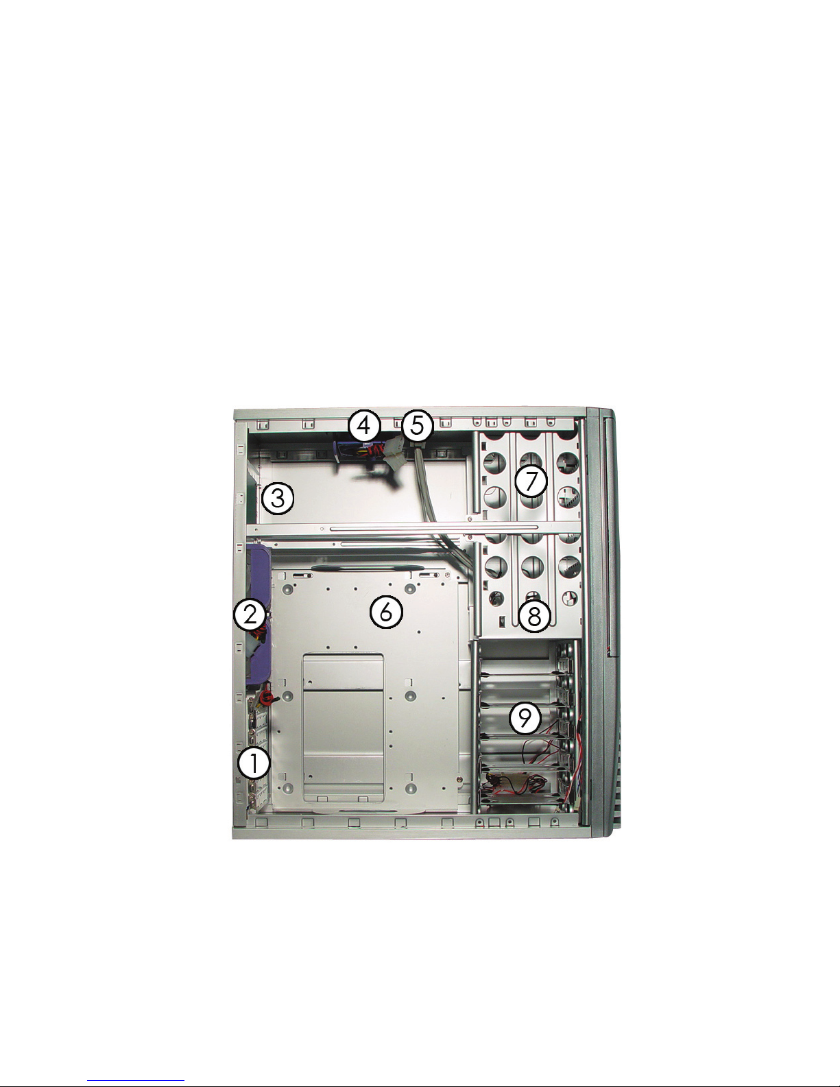
1.7 Interior Features
1_agp/pci/pcixpress expansion slots
2_dual 80mm exhaust fans
3_power supply harness
4_top 80 mm exhaust/intake fan
5_external usb/audio/firewire jacks
6_removable motherboard tray
7_5.25” drive mounts
8_3.5” drive mounts
9_interior hard drive mounts

Article Two : Installation Check List
2.1 Tool requirements
_Phillips head screwdriver
_needle nose pliers (optional)
2.2 Anti Static requirements
_anti static grounding strap
_anti static grounding mat
2.3 Other Optional requirements
_Motherboard
_Processor
_Hard drive
_Cptical drive
_Floppy disk drive
_Video card
_Sound card
Article Three : Basic Installation
3.1 Removing the side panel
_unscrew both screws from the back of the tower
_pull side panel handle outwards
_repeat on opposing side
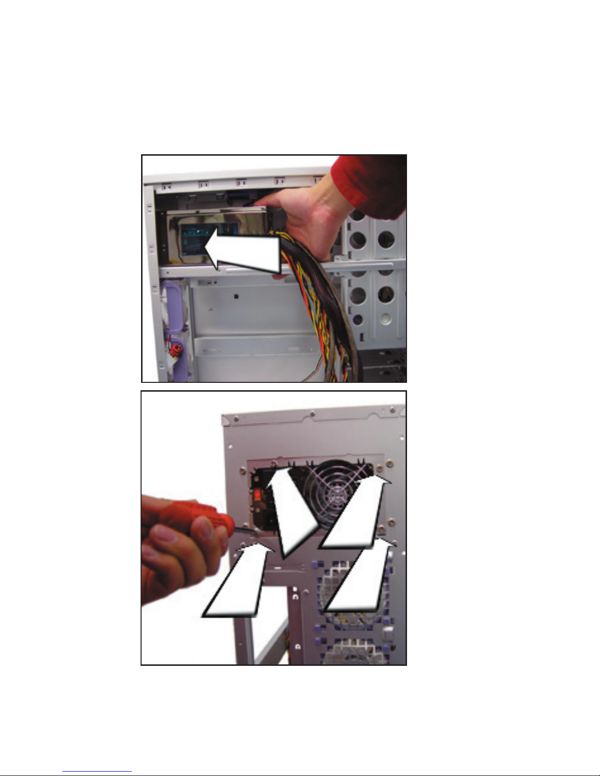
3.2 Installing the power supply
1_if there is a power supply already installed skip to 3.3
2_place power supply in the power supply harness
3_screw in all 4 screws on the back of the tower
4_switch power supply to the proper voltage (120USA)

3.3 Motherboard installation
1_configure motherboard according to manufacturer
provided manual
1a_you may need to mount the processor and
processor fan prior to mounting the mother
board in the chassis
2_remove motherboard tray by unscrewing both screws on
the right side, then lift out.
3_install I/O panel provided by the mb manufacturer
4_place motherboard accordingly on mounting screws
5_put washers provided on screws then screw in the
motherboard accordingly
6_place motherboard tray back into the case aligning the
i/o panel
7_plug in power and reset switch according to mb specs

3.4 Removing knock out metal faceplates
1_remove all plastic 5.25” covering by unscrewing them
from the back of the panel when it is open
2_use pliers and rock the metal knock out piece front to
back after a couple seconds it will fall off
3_repeat until all knockouts are removed

3.5 Installing a 3.5” floppy drive
1_remove all plastic 3.5” floppy covering by unscrewing out
from inside
2_unlatch 3.5” harness by pushing plastic harness and
pulling out.
3_unscrew metal brackets
4_slide in floppy accordingly
5_attach 3.5” drive accordingly with provided screws
6_slide harness back into assembly unit you hear a click
7_plug in IDE cable according to motheboard manual
8_plug in power according to motherboard manual
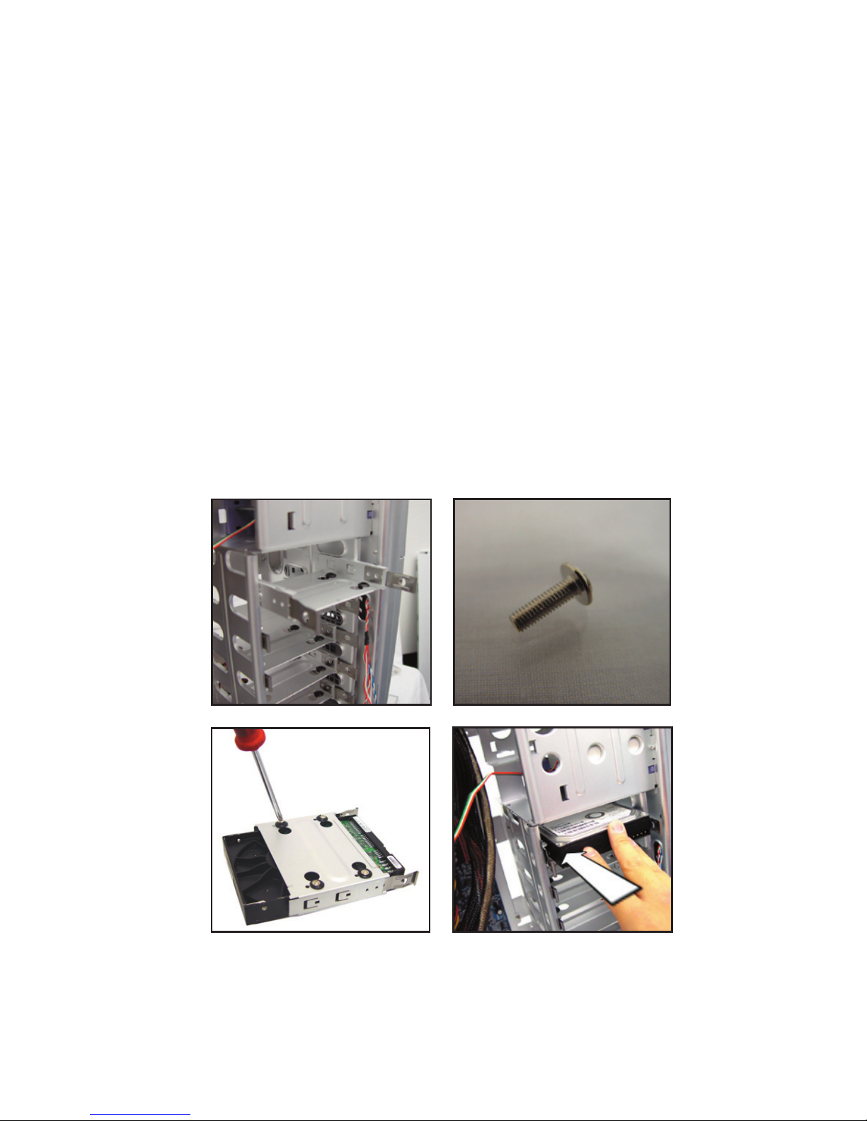
3.6 Installing IDE/SATA hard drive
1_remove the metal carriage by pushing the switch and
pulling
2_screw hard drive into carriage from the bottom with
provided screws
3_slide hard drive into assembly until you hear a click
4_repeat as necessary
3.6.1 installing an IDE hard drive
1_set jumpers to proper setting prior to install
2_plug in IDE cable according to MB manual
3_plug in power cable according to MB manual
3.6.2 installing an SATA hard drive
1_plug in SATA cable according to MB manual
2_plug in SATA power cable according to MB
manual

3.7 Installing a 5.25” peripherial device
1_attach plastic rails to peripherial device
2_side in device accordingly
3_push device into assembly until you hear a click
4_repeat as necessary
5_close the front panel
3.7.1 Optical drive installation
1_set jumpers to proper setting prior to install
2_plug in IDE cable according to MB manual
3_plug in power cable according to MB manual
3.7.2 Other device Installation
1_make sure device is configured prior to install
2_please refer to manufacturer’s user guide to
complete installation properly

3.8 Installing AGP/PCI/PCIEXPRESS devices
1_remove screw from appropriate slot
2_remove expansion panel cover
3_insert AGP/PCI/PCIEXPRESS device in proper slot
4_fasten AGP/PCI/PCIEXPRESS device with screw
5_make sure AGP/PCI/PCIEXPRESS card is secure

3.9 Replacing the side panels
1_make sure all necessary wires and screws are secure
2_slide side panel on the side of the case, aligning the
front side first
3_push in the back of the side panel
4_screw in all screws
5_repeat for otherside

Article Three : Performance Recommendations
3.1 Fan Placement
_Placing an intake fan at the front of the computer allows
fresh air to come in, and placing an exhaust fant at the
back of the computer allows hot air to flow out.
_For each intake fan u have, there should also be and
exhaust fan
3.2 Wire Management
_Having neatly organized wires in your system allows for the
heat to be dissipated
_Recommendations for tidy wire management would ei
ther to have a wire sleeve kit or us traditional zipties
_Sleeve kits also add to the visual appeal of you case, es
pecially if you have a clear window
3.3 Chassis Maintanence
_It is recommended that you keep your computer in a
room tempurature environment
_Avoid all tempurature and humidity changes when
possible
_It is recommeneded to remove any dust and debris from
your system systematically
_a clean system is a cool system

NOTES :
 Loading...